EP3810831B1 - Tuyau flexible pour le transport sous-marin des champs de production, procédé de fabrication de corps de tuyau flexible et procédé pour fournir une protection contre la corrosion à des fils d'armure d'au moins une couche d'armure de traction d'un tuyau flexible ayant une région annulaire de tuyau rompue. - Google Patents
Tuyau flexible pour le transport sous-marin des champs de production, procédé de fabrication de corps de tuyau flexible et procédé pour fournir une protection contre la corrosion à des fils d'armure d'au moins une couche d'armure de traction d'un tuyau flexible ayant une région annulaire de tuyau rompue. Download PDFInfo
- Publication number
- EP3810831B1 EP3810831B1 EP19732104.5A EP19732104A EP3810831B1 EP 3810831 B1 EP3810831 B1 EP 3810831B1 EP 19732104 A EP19732104 A EP 19732104A EP 3810831 B1 EP3810831 B1 EP 3810831B1
- Authority
- EP
- European Patent Office
- Prior art keywords
- flexible pipe
- layer
- tensile armour
- anode
- anode element
- Prior art date
- Legal status (The legal status is an assumption and is not a legal conclusion. Google has not performed a legal analysis and makes no representation as to the accuracy of the status listed.)
- Active
Links
Images



Classifications
-
- C—CHEMISTRY; METALLURGY
- C23—COATING METALLIC MATERIAL; COATING MATERIAL WITH METALLIC MATERIAL; CHEMICAL SURFACE TREATMENT; DIFFUSION TREATMENT OF METALLIC MATERIAL; COATING BY VACUUM EVAPORATION, BY SPUTTERING, BY ION IMPLANTATION OR BY CHEMICAL VAPOUR DEPOSITION, IN GENERAL; INHIBITING CORROSION OF METALLIC MATERIAL OR INCRUSTATION IN GENERAL
- C23F—NON-MECHANICAL REMOVAL OF METALLIC MATERIAL FROM SURFACE; INHIBITING CORROSION OF METALLIC MATERIAL OR INCRUSTATION IN GENERAL; MULTI-STEP PROCESSES FOR SURFACE TREATMENT OF METALLIC MATERIAL INVOLVING AT LEAST ONE PROCESS PROVIDED FOR IN CLASS C23 AND AT LEAST ONE PROCESS COVERED BY SUBCLASS C21D OR C22F OR CLASS C25
- C23F13/00—Inhibiting corrosion of metals by anodic or cathodic protection
- C23F13/02—Inhibiting corrosion of metals by anodic or cathodic protection cathodic; Selection of conditions, parameters or procedures for cathodic protection, e.g. of electrical conditions
- C23F13/06—Constructional parts, or assemblies of cathodic-protection apparatus
-
- C—CHEMISTRY; METALLURGY
- C23—COATING METALLIC MATERIAL; COATING MATERIAL WITH METALLIC MATERIAL; CHEMICAL SURFACE TREATMENT; DIFFUSION TREATMENT OF METALLIC MATERIAL; COATING BY VACUUM EVAPORATION, BY SPUTTERING, BY ION IMPLANTATION OR BY CHEMICAL VAPOUR DEPOSITION, IN GENERAL; INHIBITING CORROSION OF METALLIC MATERIAL OR INCRUSTATION IN GENERAL
- C23F—NON-MECHANICAL REMOVAL OF METALLIC MATERIAL FROM SURFACE; INHIBITING CORROSION OF METALLIC MATERIAL OR INCRUSTATION IN GENERAL; MULTI-STEP PROCESSES FOR SURFACE TREATMENT OF METALLIC MATERIAL INVOLVING AT LEAST ONE PROCESS PROVIDED FOR IN CLASS C23 AND AT LEAST ONE PROCESS COVERED BY SUBCLASS C21D OR C22F OR CLASS C25
- C23F13/00—Inhibiting corrosion of metals by anodic or cathodic protection
- C23F13/02—Inhibiting corrosion of metals by anodic or cathodic protection cathodic; Selection of conditions, parameters or procedures for cathodic protection, e.g. of electrical conditions
- C23F13/06—Constructional parts, or assemblies of cathodic-protection apparatus
- C23F13/08—Electrodes specially adapted for inhibiting corrosion by cathodic protection; Manufacture thereof; Conducting electric current thereto
- C23F13/10—Electrodes characterised by the structure
-
- F—MECHANICAL ENGINEERING; LIGHTING; HEATING; WEAPONS; BLASTING
- F16—ENGINEERING ELEMENTS AND UNITS; GENERAL MEASURES FOR PRODUCING AND MAINTAINING EFFECTIVE FUNCTIONING OF MACHINES OR INSTALLATIONS; THERMAL INSULATION IN GENERAL
- F16L—PIPES; JOINTS OR FITTINGS FOR PIPES; SUPPORTS FOR PIPES, CABLES OR PROTECTIVE TUBING; MEANS FOR THERMAL INSULATION IN GENERAL
- F16L11/00—Hoses, i.e. flexible pipes
- F16L11/04—Hoses, i.e. flexible pipes made of rubber or flexible plastics
- F16L11/08—Hoses, i.e. flexible pipes made of rubber or flexible plastics with reinforcements embedded in the wall
- F16L11/081—Hoses, i.e. flexible pipes made of rubber or flexible plastics with reinforcements embedded in the wall comprising one or more layers of a helically wound cord or wire
-
- F—MECHANICAL ENGINEERING; LIGHTING; HEATING; WEAPONS; BLASTING
- F16—ENGINEERING ELEMENTS AND UNITS; GENERAL MEASURES FOR PRODUCING AND MAINTAINING EFFECTIVE FUNCTIONING OF MACHINES OR INSTALLATIONS; THERMAL INSULATION IN GENERAL
- F16L—PIPES; JOINTS OR FITTINGS FOR PIPES; SUPPORTS FOR PIPES, CABLES OR PROTECTIVE TUBING; MEANS FOR THERMAL INSULATION IN GENERAL
- F16L11/00—Hoses, i.e. flexible pipes
- F16L11/04—Hoses, i.e. flexible pipes made of rubber or flexible plastics
- F16L11/12—Hoses, i.e. flexible pipes made of rubber or flexible plastics with arrangements for particular purposes, e.g. specially profiled, with protecting layer, heated, electrically conducting
-
- F—MECHANICAL ENGINEERING; LIGHTING; HEATING; WEAPONS; BLASTING
- F16—ENGINEERING ELEMENTS AND UNITS; GENERAL MEASURES FOR PRODUCING AND MAINTAINING EFFECTIVE FUNCTIONING OF MACHINES OR INSTALLATIONS; THERMAL INSULATION IN GENERAL
- F16L—PIPES; JOINTS OR FITTINGS FOR PIPES; SUPPORTS FOR PIPES, CABLES OR PROTECTIVE TUBING; MEANS FOR THERMAL INSULATION IN GENERAL
- F16L11/00—Hoses, i.e. flexible pipes
- F16L11/14—Hoses, i.e. flexible pipes made of rigid material, e.g. metal or hard plastics
- F16L11/16—Hoses, i.e. flexible pipes made of rigid material, e.g. metal or hard plastics wound from profiled strips or bands
-
- F—MECHANICAL ENGINEERING; LIGHTING; HEATING; WEAPONS; BLASTING
- F16—ENGINEERING ELEMENTS AND UNITS; GENERAL MEASURES FOR PRODUCING AND MAINTAINING EFFECTIVE FUNCTIONING OF MACHINES OR INSTALLATIONS; THERMAL INSULATION IN GENERAL
- F16L—PIPES; JOINTS OR FITTINGS FOR PIPES; SUPPORTS FOR PIPES, CABLES OR PROTECTIVE TUBING; MEANS FOR THERMAL INSULATION IN GENERAL
- F16L58/00—Protection of pipes or pipe fittings against corrosion or incrustation
-
- C—CHEMISTRY; METALLURGY
- C23—COATING METALLIC MATERIAL; COATING MATERIAL WITH METALLIC MATERIAL; CHEMICAL SURFACE TREATMENT; DIFFUSION TREATMENT OF METALLIC MATERIAL; COATING BY VACUUM EVAPORATION, BY SPUTTERING, BY ION IMPLANTATION OR BY CHEMICAL VAPOUR DEPOSITION, IN GENERAL; INHIBITING CORROSION OF METALLIC MATERIAL OR INCRUSTATION IN GENERAL
- C23F—NON-MECHANICAL REMOVAL OF METALLIC MATERIAL FROM SURFACE; INHIBITING CORROSION OF METALLIC MATERIAL OR INCRUSTATION IN GENERAL; MULTI-STEP PROCESSES FOR SURFACE TREATMENT OF METALLIC MATERIAL INVOLVING AT LEAST ONE PROCESS PROVIDED FOR IN CLASS C23 AND AT LEAST ONE PROCESS COVERED BY SUBCLASS C21D OR C22F OR CLASS C25
- C23F2213/00—Aspects of inhibiting corrosion of metals by anodic or cathodic protection
- C23F2213/30—Anodic or cathodic protection specially adapted for a specific object
- C23F2213/31—Immersed structures, e.g. submarine structures
-
- C—CHEMISTRY; METALLURGY
- C23—COATING METALLIC MATERIAL; COATING MATERIAL WITH METALLIC MATERIAL; CHEMICAL SURFACE TREATMENT; DIFFUSION TREATMENT OF METALLIC MATERIAL; COATING BY VACUUM EVAPORATION, BY SPUTTERING, BY ION IMPLANTATION OR BY CHEMICAL VAPOUR DEPOSITION, IN GENERAL; INHIBITING CORROSION OF METALLIC MATERIAL OR INCRUSTATION IN GENERAL
- C23F—NON-MECHANICAL REMOVAL OF METALLIC MATERIAL FROM SURFACE; INHIBITING CORROSION OF METALLIC MATERIAL OR INCRUSTATION IN GENERAL; MULTI-STEP PROCESSES FOR SURFACE TREATMENT OF METALLIC MATERIAL INVOLVING AT LEAST ONE PROCESS PROVIDED FOR IN CLASS C23 AND AT LEAST ONE PROCESS COVERED BY SUBCLASS C21D OR C22F OR CLASS C25
- C23F2213/00—Aspects of inhibiting corrosion of metals by anodic or cathodic protection
- C23F2213/30—Anodic or cathodic protection specially adapted for a specific object
- C23F2213/32—Pipes
Definitions
- the present invention relates to a flexible pipe for subsea transportation of production fluids, to a method of manufacturing a flexible pipe body, and to a method of providing corrosion protection to armour wires of at least one tensile armour layer of a flexible pipe having a breached pipe annulus region, see claims 1, 13 and 15 respectively.
- the present invention relates to the provision of tensile armour layers including monofilament armour wires having a non-circular cross section and elongate anode elements having a substantially circular cross section interposed with adjacent primary armour wire windings.
- the armour wires and anode elements are formed from different materials.
- a flexible pipe is utilised to transport production fluids, such as oil and/or gas and/or water, from one location to another.
- Flexible pipe is particularly useful in connecting a sub-sea location (which may be deep underwater, say 1000 metres or more) to a sea level location.
- the pipe may have an internal diameter of typically up to around 0.6 metres (e.g. diameters may range from 0.05 m up to 0.6 m).
- a flexible pipe is generally formed as an assembly of flexible pipe body and one or more end fittings.
- the pipe body is typically formed as a combination of layered materials that form a pressure-containing conduit.
- the pipe structure allows large deflections without causing bending stresses that impair the pipe's functionality over its lifetime.
- pipe body is generally built up as a combined structure including polymer layers and/or composite layers and/or metallic layers.
- pipe body may include polymer and metal layers, or polymer and composite layers, or polymer, metal and composite layers. Layers may be formed from a single piece such as an extruded tube or by helically winding one or more wires at a desired pitch or by connecting together multiple discrete hoops that are arranged concentrically side-by-side.
- some of the pipe layers may be bonded together or remain unbonded.
- a flexible pipe may be required to operate with external pressures ranging from 0.1 MPa to 30 MPa acting on the pipe.
- Equally, transporting oil, gas or water may well give rise to high pressures acting on the flexible pipe from within, for example with internal pressures ranging from zero to 140 MPa from bore fluid acting on the pipe.
- internal pressures ranging from zero to 140 MPa from bore fluid acting on the pipe.
- flexible pipe may also be used for shallow water applications (for example less than around 500 metres depth) or even for shore (overland) applications.
- an inner fluid retaining layer of a flexible pipe often referred to as a liner or barrier layer
- an outer fluid retaining layer referred to as an outer sheath
- an annulus region in which various metal structures may be located.
- metal structures are tensile armour windings or pressure armour windings or the like.
- cathodic protection has been utilised. Cathodic protection is a mechanism for providing corrosion protection and such cathodic protection is well known to those skilled in the art.
- CP cathodic protection
- such CP systems rely on the inclusion of metal anodes such as aluminium or zinc blocks which are less noble and thus have a lower reference potential than the metallic regions of a flexible pipe which are to be protected.
- metal anodes such as aluminium or zinc blocks which are less noble and thus have a lower reference potential than the metallic regions of a flexible pipe which are to be protected.
- the flexible pipe metals such as steel windings, will have the potential of the anode. This potential gradually increases along a length of flexible pipe body away from the anode.
- the change in potential is caused by attenuation effects due to the resistance of the structure of the metal elements as well as other factors.
- WO 01/81809 A1 (describing the preamble of claims 1, 13 and 15) relates to a flexible, armoured pipe.
- a similar electrolyte such as oxygen depleted seawater or oxygen rich seawater
- Certain embodiments of the present invention aim to provide effective local anode sites along a whole or part of a length of flexible pipe body to help overcome the issue of attenuation suffered by conventional techniques.
- said further material is more electrically reactive than said first material and is optionally circular, or square, or hexagonal, or I-shaped in cross-section.
- a further material is more reactive to a corrosive environment of a seawater holding pipe annulus region in the flexible pipe than said first material of the armour wires.
- each anode element is at least partially dissolvable in seawater.
- each anode element extends a whole length along the flexible pipe between end fittings that terminate respective ends of the flexible pipe.
- each anode element is a galvanic anode.
- each anode element comprises magnesium and/or aluminium and/or zinc.
- each anode element comprises at least one elongate strand of said a further material.
- each anode element comprises a monofilament wire or a wire-strand comprising a plurality of elongate filaments of said a further material.
- the wire-strand anode elements thickness in a radial direction is between 110% and 135% of the thickness of the tensile armour wires in the same tensile armour layer.
- each anode element comprises an elongate core, comprising a still further material, that extends along a whole length of the anode element.
- each anode element comprises a perforated casing, comprising a still further material, that extends along a whole length of the anode element.
- the tensile armour layer comprises a plurality of elongate anode elements.
- the plurality of elongate anode elements are spaced apart circumferentially in the tensile armour layer.
- a thickness of each monofilament anode element in a radial direction is less than a corresponding thickness of each of the tensile armour wires in a common tensile armour layer.
- a thickness is about 95% to 98% of said a corresponding thickness.
- the tape layer comprises said at least one helically wound electrically conductive tape element and at least one electrically insulating tape element with windings of the electrically insulating tape element being interposed between windings of the electrically conductive tape element.
- the tensile armour layer comprises a radially inner tensile armour layer of the flexible pipe and the tape layer is interposed between the tensile armour layer and a pressure armour layer disposed radially outside of the fluid retaining layer.
- the method further comprises helically winding a plurality of discrete elongate anode elements in a circumferentially spaced apart relationship with the armour wires in the tensile armour layer.
- the method further comprises winding each elongate anode element between immediately adjacent armour wires.
- the method further comprises helically winding a plurality of discrete elongate anode elements together in a side-by-side arrangement as a group whereby each group of discrete elongate anode elements is thereby disposed between immediately adjacent armour wires.
- the method further comprises simultaneously winding a plurality of groups of discrete elongate anode elements, in a circumferentially spaced apart relationship, with the armour wires in a tensile armour layer.
- a third aspect of the present invention there is provided a method of providing corrosion protection to armour wires of at least one tensile armour layer of a flexible pipe for subsea transportation of production fluids as defined in claim 15, and comprising:
- the method further comprises said step of providing an electron pathway comprises providing an electron pathway between the first and further material whereby the first material is different from the further material and the further material is more electrically reactive than the first material.
- Certain embodiments of the present invention provide wires of an outer tensile armour layer shielding inner wires and this provides local anode sites to long pipes overcoming attenuation limits.
- Certain embodiments of the present invention extend a maximum length of pipes that can be produced and still protected by cathodic protection systems. This can optionally be attained without the need for a mid-line connection which would otherwise be required according to conventional techniques.
- Certain embodiments of the present invention provide anodes which can be secured to end fittings or to flexible pipe body itself along a length of a flexible pipe and these anodes are connected to elongate anode elements that run as a surrogate for tensile armour wires internally within flexible pipe body along a whole or part of the length of the flexible pipe body.
- Certain embodiments of the present invention replace one or several tensile armour wires in a flexible pipe with an anode element sharing a suitable geometry to provide a distributed cathodic protection to flexible pipes.
- Such anode elements provide local protection in the event of a shield breach on a subsea pipe.
- Certain embodiments of the present invention provide a method of effectively electrically connecting metallic elements from multiple layers in flexible pipe body together. As a result resistance along a length of flexible pipe is reduced thus reducing attenuation effects.
- Certain embodiments of the present invention provide an anti-fretting layer that can be used between opposed layer in flexible pipe body and which also includes one or more electrically conducting elements which bridge the space between the separated layers to help provide an electrical connection at repeated locations along the length of flexible pipe body.
- the illustrated flexible pipe is an assembly of a portion of pipe body and one or more end fittings (not shown in Figure 1 ) in each of which a respective end of the pipe body is terminated.
- Figure 1 illustrates how pipe body 100 is formed from a combination of layered materials that form a pressure-containing conduit.
- the pipe body may include one or more layers comprising composite materials, forming a tubular composite layer.
- the layer thicknesses are shown for illustrative purposes only.
- composite is used to broadly refer to a material that is formed from two or more different materials, for example a material formed from a matrix material and reinforcement fibres.
- a tubular composite layer is thus a layer having a generally tubular shape formed of composite material.
- a tubular composite layer is a layer having a generally tubular shape formed from multiple components one or more of which is formed of a composite material.
- the layer or any element of the composite layer may be manufactured via an extrusion, pultrusion or deposition process or, by a winding process in which adjacent windings of tape which themselves have a composite structure are consolidated together with adjacent windings.
- the composite material regardless of manufacturing technique used, may optionally include a matrix or body of material having a first characteristic in which further elements having different physical characteristics are embedded.
- elongate fibres which are aligned to some extent or smaller fibres randomly orientated can be set into a main body or spheres or other regular or irregular shaped particles can be embedded in a matrix material, or a combination of more than one of the above.
- the matrix material is a thermoplastic material
- the thermoplastic material is polyethylene or polypropylene or nylon or PVC or PVDF or PFA or PEEK or PTFE or alloys of such materials with reinforcing fibres manufactured from one or more of glass, ceramic, basalt, carbon, carbon nanotubes, polyester, nylon, aramid, steel, nickel alloy, titanium alloy, aluminium alloy or the like or fillers manufactured from glass, ceramic, carbon, metals, buckminsterfullerenes, metal silicates, carbides, carbonates, oxides or the like.
- the pipe body 100 illustrated in Figure 1 includes an internal pressure sheath 110 which acts as a fluid retaining layer and comprises a polymer layer that ensures internal fluid integrity.
- the layer provides a boundary for any conveyed fluid. It is to be understood that this layer may itself comprise a number of sub-layers. It will be appreciated that when a carcass layer 120 is utilised the internal pressure sheath is often referred to by those skilled in the art as a barrier layer. In operation without such a carcass (so-called smooth bore operation) the internal pressure sheath may be referred to as a liner.
- a barrier layer 110 is illustrated in Figure 1 .
- the carcass layer 120 is a pressure resistant layer that provides an interlocked construction that can be used as the innermost layer to prevent, totally or partially, collapse of the internal pressure sheath 110 due to pipe decompression, external pressure, and tensile armour pressure and mechanical crushing loads.
- the carcass is a crush resistant layer. It will be appreciated that certain embodiments of the present invention are thus applicable to 'rough bore' applications (with a carcass) whilst certain other embodiments are applicable to "smooth bore” applications.
- the carcass layer is a metallic layer.
- the carcass layer is formed from stainless steel, corrosion resistant nickel alloy or the like.
- Aptly the carcass layer is formed from a composite, polymer, or other material, or a combination of materials and components.
- a carcass layer is radially positioned within the barrier layer.
- the pressure armour layer 130 is a pressure resistant layer that provides a structural layer that increases the resistance of the flexible pipe to internal and external pressure and mechanical crushing loads. The layer also structurally supports the internal pressure sheath.
- the pressure armour layer is formed as a tubular layer.
- the pressure armour layer consists of an interlocked construction of wires with a lay angle close to 90°. Aptly the lay angle is between 80° and 90° to the axis of the pipe body.
- the pressure armour layer is a metallic layer.
- the pressure armour layer is formed from carbon steel, aluminium alloy or the like.
- Aptly the pressure armour layer is formed from a pultruded composite interlocking layer.
- the pressure armour layer is formed from a composite formed by extrusion or pultrusion or deposition or winding, followed by consolidation.
- a pressure armour layer is positioned radially outside an underlying barrier layer.
- the flexible pipe body also includes a first tensile armour layer 140 and second tensile armour layer 150.
- Each tensile armour layer is used to sustain tensile loads and optionally also internal pressure.
- the primary tensile armour windings are metal monofilament wires (for example steel, stainless steel or titanium or the like).
- the primary tensile armour windings are polymer composite tape windings (for example provided with either thermoplastic, for instance nylon, matrix composite or thermoset, for instance epoxy, matrix composite). The composite tape is thus formed into a monofilament wire that can be wound.
- the tensile armour layer is formed from a plurality of primary monofilament wires.
- tensile armour layers are counter-wound in pairs.
- the tensile armour layers are metallic layers.
- the tensile armour layers are primary windings formed from carbon steel, stainless steel, titanium alloy, aluminium alloy or the like.
- the tensile armour layers are formed from a composite, polymer, or other material, or a combination of materials.
- the flexible pipe body includes optional layers of tape 160, 170, 180 which help contain underlying layers and to some extent prevent abrasion between adjacent layers.
- the tape layer may optionally be a polymer or composite or a combination of materials, also optionally comprising a tubular composite layer. Tape layers can be used to help prevent metal-to-metal contact to help prevent wear. Tape layers over tensile armours can also help prevent "birdcaging".
- the flexible pipe body also includes optional layers of insulation and/or metal winding or polymer layers or tape layers or layers including special materials such as optical fibres and an outer sheath 190, which comprises a polymer layer used to protect the pipe against penetration of seawater and other external environments, corrosion, abrasion and mechanical damage.
- An outer sheath 190 which comprises a polymer layer used to protect the pipe against penetration of seawater and other external environments, corrosion, abrasion and mechanical damage.
- Any thermal insulation layer helps limit heat loss through the pipe wall to the surrounding environment and may comprise layers of tape or at least one extruded layer of insulating material.
- Each flexible pipe comprises at least one portion, referred to as a segment or section, of pipe body 100 together with an end fitting located at at least one end of the flexible pipe.
- An end fitting provides a mechanical device which forms the transition between the flexible pipe body and a connector.
- the different pipe layers as shown, for example, in Figure 1 are terminated in the end fitting in such a way as to transfer the load between the flexible pipe and the connector.
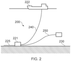
- Figure 2 illustrates a riser assembly 200 suitable for transporting production fluid such as oil and/or gas and/or water from a sub-sea location 221 to a floating facility 222.
- the sub-sea location 221 includes a sub-sea flow line 225.
- the flexible flow line 225 comprises a flexible pipe, wholly or in part, resting on the sea floor 230 or buried below the sea floor and used in a static application.
- the floating facility may be provided by a platform and/or buoy or, as illustrated in Figure 2 , a ship.
- the riser assembly 200 is provided as a flexible riser, that is to say a flexible pipe 240 connecting the ship to the sea floor installation.
- the flexible pipe may be in segments of flexible pipe body with connecting end fittings.
- riser there are different types of riser, as is well-known by those skilled in the art.
- Certain embodiments of the present invention may be used with any type of riser, such as a freely suspended (free-hanging, catenary riser), a riser restrained to some extent (buoys, chains), totally restrained riser or enclosed in a tube (I or J tubes).
- I or J tubes Some, though not all, examples of such configurations can be found in API 17J.
- Figure 2 also illustrates how portions of flexible pipe can be utilised as a jumper 250.
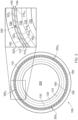
- Figure 3 illustrates a cross section through a length of the flexible pipe body 100 shown in Figure 1 in more detail.
- a carcass layer 120 supports a barrier layer 110.
- An inner surface of the barrier layer 110 provides the fluid retaining surface which defines a bore region 300 along which transport of production fluids can take place. The direction of flow of the production fluid would be in or out of the page in Figure 3 .
- An innermost tape layer 160 is located on a radially outermost surface of the pressure armour layer 130 to help support windings of the pressure armour layer. This innermost tape layer 160 also helps provide anti-fretting effects between the inner/underlying pressure armour layer 130 and windings of the first tensile armour layer 140. Adjacent windings 310 0,1...m of tensile armour wire of the first tensile armour layer are illustrated in Figure 3 .
- the innermost tape layer 160 is an intermediate layer between a pressure armour layer 130 and an inner tensile armour layer 140.
- a further tape layer 170 is an intermediate layer between the first tensile armour layer 140 and the second tensile armour 150. Adjacent windings 320 o,1...n of the second tensile armour wire help provide the outer tensile armour layer 150.
- a further tape layer 180 is wound outside the second tensile armour layer 150. This helps provide support and anti-birdcaging effects to the tensile armour layer/s.
- the outer sheath 190 is formed outside the outer tape layer 180.
- This further tape layer 180 is an intermediate layer between the outer tensile armour layer and an overlying layer.
- Figure 3 also helps show how each tensile armour wire has an aspect ratio of greater than 1:2. That is to say a cross section of each monofilament armour wire has a length greater than twice its thickness (in the radial direction when wound).
- Figure 3 still further helps to show how the outermost tensile armour layer includes at least one helically wound elongate anode element 350 1 , 2 , 3 .
- anode element 350 1 , 2 , 3 Three such windings are shown in Figure 3 .
- One of these 350 2 is shown more clearly in the enlarged view of a portion of the cross section of the flexible pipe body.
- anode elements can be wound as circumferentially spaced apart elements (as shown in Figure 3 ) or can be grouped together.
- groups of anode elements 350 can be circumferentially spaced apart through the cross section.
- the tensile armour wire aspect ratio is a multiple of the aspect ratio of the anode element then the multiple anode elements may replace only a single tensile armour wire and the anode elements may be evenly distributed around the circumference of the tensile armour layer.
- the aspect ratio of the tensile armour wire is 3:1, and there are three evenly distributed anode elements, of aspect ratio 1:1, roughly 120 degrees apart wound within the layer.
- Each anode element 350 is an elongate body, substantially of aspect ratio 1:1, that can be helically wound, in part, in place of a tensile armour wire.
- Each anode element has a length that extends a significant length along the flexible pipe body.
- each anode element extends all the way along a flexible pipe between end fittings.
- the anode elements may only extend a predetermined distance within the flexible pipe body. For example half a whole length or a third of a whole length or 20 m or 50 m or the like.
- Each anode element can be of a similar or different length.
- the anode element shown in Figure 3 is a monofilament structure that has a circular cross section.
- the area of the cross-section of an anode element is therefore 50% or less of a corresponding area of the cross-section of the tensile armour wires with aspect ratio of at least 2:1.
- Each anode element is manufactured from, or at least comprises, a material that is different from a first material which the tensile armour is comprised of.
- the further material of the anode elements is more electrically reactive than the first material.
- the material of the anode windings is more reactive to a corrosive environment of a seawater holding annulus. That is to say if in use an outer sheath is breached and the annulus region in the flexible pipe floods with seawater the anode windings material is more reactive to the corrosive environment than the material of the primary tensile armour windings.
- the further material of the anode elements is at least partially dissolvable in seawater.
- each anode element behave as galvanic anodes.
- each anode element is a magnesium and/or aluminium and/or zinc wire, or an alloy of these, separately, or in combination.
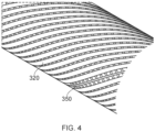
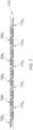
- Figure 4 helps illustrate how a round anode wire 350 can be helically wound in the tensile armour layer 150 between adjacent windings 320 of the monofilament tensile armour windings. Only the primary windings and anode windings of a single flexible pipe body layer are shown in Figure 4 for the sake of clarity.
- FIG. 5A illustrates an alternative embodiment of the present invention in many ways similar to the embodiment previously described.
- an outer tensile armour layer 150 is provided by windings of a primary tensile armour wire and windings of an anode element.
- the tensile armour wires are monofilament structures having an aspect ratio of greater than 1:2 (that is to say they have a width greater than their height).
- Each anode element is a multi-filament structure with filaments spirally wound into a wire-strand or wire-rope arrangement.
- Some of the filaments have a cross-section greater than others for the purpose of improving the packing of the wire-strand or wire-rope (increasing cross-sectional area, and reducing free volume in the cross-section of the anode element).
- All of the anode element filaments in Figure 3 , 4 and 5A have a circular cross section.
- the overall cross-section of the anode element, which itself is formed from multiple components, is substantially circular, and therefore has an aspect ratio of 1:1. It will be appreciated that some filaments may have alternative shapes in cross-section and/or may be manufactured from, or contain, different materials.
- the cross-sectional area of the combined cross-section of all of the filaments of each anode element (that is to say the cross section of the anode element) has an area that is 50% or less of a corresponding area of the cross section of the primary tensile armour windings, and an aspect ratio substantially of 1:1.
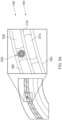
- FIG. 5B shows the wire-strand anode element of a thickness in a radial direction which is slightly greater than the thickness of the tensile armour wires in the same tensile armour layer.
- the amount by which the wire-strand or wire-rope anode element thickness must be greater than the thickness of the tensile armour layer 140, to break through the tape layers 170 and 160 and achieve continuity with them will depend on the thickness of those tape layers. Tape layers may sum cumulatively (with overlaps) up to around 1mm in radial thickness, therefore the anode element thickness may need to be up to 2mm thicker than the tensile armour layer in which the anode element is wound.
- the anode element may be as little as 10% thicker than the tensile armour wires 310 of the tensile armour layer 140; depending on the flexible pipe body design and the tape materials however the anode element may be as much as 35% thicker than the tensile armour wires 310 of the same tensile armour layer 140.
- One or more of the filaments, and optionally all of the filaments, that make up the windable anode element comprise a material different from the material of the tensile armour windings.
- the material of the anode elements is more electrically active than the material of the tensile armour windings.
- Figures 5C to 5E illustrate further alternative anode elements shapes with aspect ratios substantially of 1:1, which may be selectable or preferable, in order to improve design parameters for the flexible pipe body (for instance, to increase the tensile armour layer fraction-fill, an anode element approximating the negative of the shape of the edges of the tensile armour wires may be selected, and/or to maximise the contact area with over-lying or under-lying conductive tapes, as can be seen in the Figures 5C to 5E.
- Figure 5C illustrates a H (or hourglass) shaped cross section for an anode element.
- Figure 5D illustrates a square with truncated corner (Octagon) shaped cross section.
- Figure 5E illustrates a square cross section.
- Figure 6 illustrates a still further embodiment of the present invention in which an inner tensile layer 140 is radially inside an outer tensile layer 150.
- An outer tape layer is radially outside the outer tensile layer.
- An inner tape layer 160 is radially inside the inner tensile layer.
- An intermediate tape layer is between the inner and outer tensile armour layers.
- the outer tensile layer has at least one elongate and windable anode element 650 wound between the monofilament tensile armour windings.
- the tensile armour layer can include just one anode element or can include multiple helically wound elongate elements. The anode elements can be wound separately between adjacent primary tensile armour windings or can be wound in groups between adjacent tensile armour windings.
- the anode element 650 in Figure 6 has a core 660 and an outer casing 670.
- the outer casing has perforations 675 (shown via dotted lines) that make the casing non-fluid-tight. Strands (seven shown in Figure 6 ) of an anode material are located between the core 660 and casing 670.
- the core provides a strength to the anode element.
- the casing provides a strength to the anode element.
- a core and surrounding anode strands without a casing can be utilised.
- a perforated casing and inner anode filaments (or a single internal monofilament anode wire) can be used without a core.
- the perforated casing provides a crush resistance to radial forces and/or tensile strength.
- the core provides a support for the surrounding filaments of anode material and/or tensile strength.
- Figure 7 helps illustrate an intermediate tape layer 170 in more detail. It will be appreciated that the further intermediate tape layers 160, 180 could be similarly provided.
- the tape layer is a relatively thin layer formed by winding thin, long, substantially flat, strips helically around an underlying layer.
- the elongate strips of tape for certain intermediate layers can be an electrically insulating material and are used to provide anti-fretting properties (preventing adjacent metallic layers from rubbing against each other).
- an intermediate tape layer can be formed by winding two different strips each having different characteristics.
- an electrically insulating tape formed by polypropylene or the like is wound over an underlying layer (in the example shown in Figure 7 over the innermost tensile armour layer 140).
- the tape is thin and flexible so that adjacent windings 700 0,1 ...4 of tape overlap and curve.
- Windings 710 0,1...4 of a further strip-like tape are illustrated in Figure 7 .
- These are formed from a metallic material such as steel or the like.
- Other electrically conducting materials such as, but not limited to, copper, aluminium, nickel, gold or silver foil or tapes comprising alloys of these or comprising other conductive materials such as graphene or the like could optionally be utilised.
- the electrically insulating windings and electrically conductive windings are interposed.
- the tape layer provides a combination of cheap and flexible anti-fretting characteristics together with an electrically conductive pathway which electrically connects an underlying layer such as a metallic underlayer with an overlying layer such as a metallic overlayer (for example anode elements and/or primary monofilament tensile armour wire windings of a first tensile armour layer 140 can be electrically connected to a second tensile armour layer 150).
- an tensile armour layer 140 can be electrically connected to a second tensile armour layer 150.
- the windings (primary and/or anode element) of an overlying layer and the windings of an underlying layer are electrically interconnected via an intermediate layer.
- a net electrical resistance offered by any metallic layer which extends along a length of the flexible pipe body is reduced.
- the thicknesses of each type of tape may vary and do not have to be similar, as is shown in Figure 7 .
- the electrically insulating windings may be twice the thickness of the electrically conductive windings, or even greater, for instance up to 50 times thicker (an example being a thin metal foil of thickness 0.05mm is applied as a conductive tape with an insulating polypropylene tape of 2.5mm thickness).
- An intermediate tape layer which includes electrically conducting elements and electrically insulating elements enables a variety of materials to be used and makes use of material characteristics to the best of those materials ability.
- electrically insulating materials can be utilised which provide superior anti-fretting and/or support capabilities.
- a material that is highly electrically conductive can be utilised and distributed as a winding throughout the intermediate layer to provide a bridge forming an electrical connection between otherwise spaced apart layers.
- the intermediate layer shown in Figure 7 includes an electrically insulating tape wound adjacent to, and sequentially alternating with, an electrically conductive tape it is possible according to certain embodiments of the present invention to utilise multiple insulating tape windings with a single electrically insulating tape winding or vice versa depending upon desire.
- windings for the intermediate layers can be formed from only electrically conductive tape.
- the tapes are wound helically around an underlying layer using a winding station that rotates with one or more sources of tape feeding the insulating tape/s and electrically conducting tape/s to respective touchdown points.
- Those touchdown points enable each continuous elongate tape to be simultaneously wound albeit at offset positions circumferentially and/or longitudinally.
- immediately next windings of a different tape can have a 0-90% overlap with an immediately preceding winding (which may be of the same or different tape type).
Landscapes
- Engineering & Computer Science (AREA)
- General Engineering & Computer Science (AREA)
- Mechanical Engineering (AREA)
- Chemical & Material Sciences (AREA)
- Materials Engineering (AREA)
- Metallurgy (AREA)
- Organic Chemistry (AREA)
- Rigid Pipes And Flexible Pipes (AREA)
- Prevention Of Electric Corrosion (AREA)
Claims (15)
- Tuyau flexible destiné au transport sous-marin de fluides de production, comprenant :une couche de rétention de fluide (110) ;une gaine externe (190) ; etau moins une couche d'armure de traction (140, 150) comprenant une pluralité de fils d'armure monofilament enroulés en
hélice (310, 320, 510, 520, 610, 620) d'un premier matériau, ayant chacun une section transversale non circulaire avec un rapport d'aspect supérieur à 1:2 disposée entre la couche de rétention de fluide (110) et la gaine externe (190) ; et caractérisé en ce que :
la couche d'armure de traction (140, 150) comprend en outre au moins un élément d'anode allongé enroulé en hélice (350, 550, 650) ayant essentiellement un rapport d'aspect de section transversale de 1:1 et comprenant un autre matériau, interposé entre les fils d'armure (310, 320, 510, 520, 610, 620), la section transversale de l'élément d'anode ayant une zone qui est égale ou inférieure à 50 % d'une zone correspondante de ladite section transversale non circulaire. - Tuyau flexible selon la revendication 1 dans lequel ledit autre matériau est plus réactif électriquement que ledit premier matériau et est éventuellement de section transversale circulaire, ou carrée, ou hexagonale, ou en forme de L, et éventuellement ledit un autre matériau de chaque élément
d'anode (350, 550, 650) comprend du magnésium et/ou de l'aluminium et/ou du zinc. - Tuyau flexible selon la revendication 1 ou la revendication 2, comprenant en outre :
ledit un autre matériau est plus réactif à un environnement corrosif d'une région annulaire de tuyau contenant de l'eau de mer dans le tuyau flexible que ledit premier matériau des fils d'armure (310, 320, 510, 520, 610, 620) et éventuellement ledit un autre matériau de chaque élément d'anode (350, 550, 650) est au moins partiellement dissoluble dans de l'eau de mer. - Tuyau flexible selon l'une quelconque revendication précédente dans lequel chaque élément d'anode (350, 550, 650) est une anode galvanique et éventuellement chaque élément d'anode (350, 550, 650) s'étend sur toute une longueur le long du tuyau flexible entre des raccords d'extrémité qui terminent les extrémités respectives du tuyau flexible.
- Tuyau flexible selon l'une quelconque revendication précédente dans lequel chaque élément d'anode (350, 550, 650) comprend au moins un toron allongé dudit un autre matériau.
- Tuyau flexible selon la revendication 5, comprenant en outre :
chaque élément d'anode (350, 550, 650) comprend un fil monofilament ou un toron de fils comprenant une pluralité de filaments allongés dudit un autre matériau et éventuellement l'épaisseur des éléments d'anode de toron de fils dans une direction radiale est comprise entre 110 % et 135 % de l'épaisseur des fils d'armure de traction (310, 320, 510, 520, 610, 620) dans la même couche d'armure de traction (140, 150). - Tuyau flexible selon l'une quelconque des revendications 1 à 5, comprenant en outre :
chaque élément d'anode (650) comprend un noyau allongé, comprenant encore un autre matériau, qui s'étend le long sur toute une longueur de l'élément d'anode (650) et éventuellement ledit encore un autre matériau du noyau a une résistance supérieure à une résistance dudit autre matériau. - Tuyau flexible selon l'une quelconque des revendications 1 à 5, comprenant en outre :
chaque élément d'anode (650) comprend une enveloppe perforée, comprenant encore un autre matériau, qui s'étend le long sur toute une longueur de l'élément d'anode (650) et éventuellement ledit encore un autre matériau de l'enveloppe perforée a une résistance supérieure à la résistance dudit autre matériau. - Tuyau flexible selon l'une quelconque revendication précédente, comprenant en outre :
la couche d'armure de traction (310, 320, 510, 520, 610, 620) comprend une pluralité d'éléments d'anode allongés (350, 550, 650) et éventuellement la pluralité d'éléments d'anode allongés (350, 550, 650) sont espacés circonférentiellement dans la couche d'armure de traction (140, 150), et éventuellement les éléments d'anode allongés (350, 550, 650) sont répartis de manière uniforme circonférentiellement dans la couche d'armure de traction (140, 150). - Tuyau flexible selon l'une quelconque revendication précédente, comprenant en outre :
une épaisseur de chaque élément d'anode monofilament (350) dans une direction radiale, est inférieure à une épaisseur correspondante de chacun des fils d'armure de traction (310, 320) dans une couche d'armure de traction (140, 150) commune et éventuellement ladite épaisseur est d'environ 95 % à 98 % de ladite une épaisseur correspondante. - Tuyau flexible selon l'une quelconque revendication précédente, comprenant en outre :
au moins une couche de bande (160, 170, 180) sur une surface radialement interne et/ou radialement externe de la couche d'armure de traction (140, 150), comprenant au moins un élément de bande électriquement conducteur enroulé en hélice (710) et éventuellement la couche de bande (160, 170, 180) comprend au moins un élément de bande électriquement isolant (700) avec des enroulements de l'élément de bande électriquement isolant (700) étant interposés entre des enroulements de l'élément de bande électriquement conducteur (710). - Tuyau flexible selon la revendication 11, comprenant en outre :
la couche d'armure de traction comprend une couche d'armure de traction (140) radialement interne du tuyau flexible et la couche de bande (160) est interposée entre la couche d'armure de traction (140) et une couche d'armure de pression (130) disposée radialement à l'extérieur de la couche de rétention de fluide (110). - Procédé de fabrication d'un corps de tuyau flexible, comprenant les étapes consistant à :fournir une couche de rétention de fluide (110) ;le procédé étant caractérisé par :la fourniture d'au moins une couche d'armure de traction (140, 150) en enroulant en hélice des fils d'armure de traction (310, 320, 510, 520, 610, 620) d'un premier matériau, chacun ayant une section transversale avec un rapport d'aspect supérieur à 1:2, sur une couche sous-jacente ;enrouler simultanément en hélice au moins un élément d'anode allongé (350, 550, 650) ayant sensiblement un rapport d'aspect de section transversale de 1:1 qui a une zone qui est égale ou inférieure à 50 % d'une zone correspondante de ladite section transversale, et comprenant un autre matériau différent dudit premier matériau, avec les fils d'armure selon lesquels ledit au moins un élément d'anode est interposé entre des fils d'armure adjacents ; etfournir une gaine externe (190).
- Procédé selon la revendication 13, comprenant en outre :
l'enroulement en hélice d'une pluralité d'éléments d'anode allongés (350, 550, 650) discrets dans une relation circonférentiellement espacée avec les fils d'armure (310, 320, 510, 520, 610, 620) dans la couche d'armure de traction. - Procédé de fourniture de protection contre la corrosion à des fils d'armure (310, 320, 510, 520, 610, 620) d'au moins une couche d'armure de traction (140, 150) d'un tuyau flexible, le procédé étant caractérisé par :
la fourniture d'un tuyau flexible destiné au transport sous-marin de fluides de production selon l'une quelconque des revendications 1 à 12 ayant une région annulaire de tuyau brisée, comprenant :la fourniture d'une voie d'électrons entre la pluralité de fils d'armure enroulés en hélice (310, 320, 510, 520, 610, 620) du premier matériau dans l'au moins une couche d'armure de traction (140, 150) et l'au moins un élément d'anode allongé enroulé en hélice (350, 550, 650) de l'autre matériau ; etlorsque l'eau de mer pénètre dans une région annulaire du tuyau flexible par le biais d'une brisure de gaine externe, la fourniture d'une voie d'ions entre chaque élément d'anode (350, 550, 650) et l'eau de mer.
Applications Claiming Priority (2)
| Application Number | Priority Date | Filing Date | Title |
|---|---|---|---|
| GBGB1810228.5A GB201810228D0 (en) | 2018-06-21 | 2018-06-21 | Pipe body cathodic protection |
| PCT/GB2019/051662 WO2019243782A1 (fr) | 2018-06-21 | 2019-06-14 | Protection cathodique de corps de tuyau |
Publications (2)
| Publication Number | Publication Date |
|---|---|
| EP3810831A1 EP3810831A1 (fr) | 2021-04-28 |
| EP3810831B1 true EP3810831B1 (fr) | 2025-05-21 |
Family
ID=63042834
Family Applications (1)
| Application Number | Title | Priority Date | Filing Date |
|---|---|---|---|
| EP19732104.5A Active EP3810831B1 (fr) | 2018-06-21 | 2019-06-14 | Tuyau flexible pour le transport sous-marin des champs de production, procédé de fabrication de corps de tuyau flexible et procédé pour fournir une protection contre la corrosion à des fils d'armure d'au moins une couche d'armure de traction d'un tuyau flexible ayant une région annulaire de tuyau rompue. |
Country Status (7)
| Country | Link |
|---|---|
| US (1) | US11592125B2 (fr) |
| EP (1) | EP3810831B1 (fr) |
| CN (1) | CN112513331A (fr) |
| DK (1) | DK3810831T3 (fr) |
| GB (1) | GB201810228D0 (fr) |
| MY (1) | MY209151A (fr) |
| WO (1) | WO2019243782A1 (fr) |
Families Citing this family (1)
| Publication number | Priority date | Publication date | Assignee | Title |
|---|---|---|---|---|
| CN117512601B (zh) * | 2023-11-02 | 2026-03-24 | 常州大学 | 一种弯管液固两相流冲刷腐蚀抑制装置 |
Family Cites Families (12)
| Publication number | Priority date | Publication date | Assignee | Title |
|---|---|---|---|---|
| FR2286331A1 (fr) * | 1974-09-24 | 1976-04-23 | Inst Francais Du Petrole | Conduites flexibles protegees contre la corrosion |
| ES241999Y (es) | 1978-03-14 | 1979-12-16 | Una tuberia para transportar petroleo crudo. | |
| NO172608C (no) | 1991-04-25 | 1993-08-11 | Alcatel Stk As | Fleksibel undersjoeisk linje |
| DK200001707A (da) | 2000-04-25 | 2000-11-15 | Nkt Flexibles Is | Armeret fleksibelt rør samt anvendelse af samme |
| FR2816691B1 (fr) * | 2000-11-10 | 2002-12-27 | Coflexip | Dispositif de protection cathodique des conduites flexibles |
| US7081187B1 (en) * | 2002-07-24 | 2006-07-25 | Matcor, Inc. | Internal cathodic protection system |
| FR2875285B1 (fr) | 2004-09-13 | 2006-11-03 | Technip France Sa | Canalisations flexibles a conduites multiples preservees de la corrosion |
| GB201018538D0 (en) * | 2010-11-03 | 2010-12-15 | Wellstream Int Ltd | Parameter sensing |
| AU2013231726B2 (en) * | 2012-03-13 | 2017-04-27 | National Oilwell Varco Denmark I/S | An unbonded flexible pipe with an optical fiber containing layer |
| BR112014025219A2 (pt) * | 2012-04-12 | 2017-07-11 | Nat Oilwell Varco Denmark Is | método para produzir um tubo flexível não unido, e, tubo flexível não unido |
| EP2662524B1 (fr) * | 2012-05-08 | 2017-07-26 | GE Oil & Gas UK Limited | Corps de tuyau flexible avec élément de flottaison et son procédé de production |
| CA2919122C (fr) * | 2013-08-02 | 2021-06-15 | Kristian Glejbol | Tuyau souple non lie et systeme en mer comprenant un tuyau souple non lie |
-
2018
- 2018-06-21 GB GBGB1810228.5A patent/GB201810228D0/en not_active Ceased
-
2019
- 2019-06-14 CN CN201980041578.2A patent/CN112513331A/zh active Pending
- 2019-06-14 EP EP19732104.5A patent/EP3810831B1/fr active Active
- 2019-06-14 DK DK19732104.5T patent/DK3810831T3/da active
- 2019-06-14 MY MYPI2020006174A patent/MY209151A/en unknown
- 2019-06-14 US US17/252,905 patent/US11592125B2/en active Active
- 2019-06-14 WO PCT/GB2019/051662 patent/WO2019243782A1/fr not_active Ceased
Also Published As
| Publication number | Publication date |
|---|---|
| CN112513331A (zh) | 2021-03-16 |
| GB201810228D0 (en) | 2018-08-08 |
| US20210262592A1 (en) | 2021-08-26 |
| WO2019243782A1 (fr) | 2019-12-26 |
| MY209151A (en) | 2025-06-24 |
| EP3810831A1 (fr) | 2021-04-28 |
| DK3810831T3 (da) | 2025-07-14 |
| US11592125B2 (en) | 2023-02-28 |
| BR112020025904A2 (pt) | 2021-03-16 |
Similar Documents
| Publication | Publication Date | Title |
|---|---|---|
| EP3596257B1 (fr) | Fourniture de continuité électrique et/ou de support radial | |
| US9016326B2 (en) | Thermal insulation of flexible pipes | |
| EP2662524A1 (fr) | Corps de tuyau flexible avec élément de flottaison et son procédé de production | |
| WO2016170360A1 (fr) | Composants de tuyau flexible et procédé de fabrication de tuyau flexible | |
| EP3478999B1 (fr) | Protection sacrificielle | |
| EP3510311B1 (fr) | Couche verrouillée et procédé de fabrication | |
| US11592125B2 (en) | Pipe body cathodic protection | |
| EP2791564B1 (fr) | Corps de tuyau flexible et méthode | |
| EP4551853A1 (fr) | Couche composite et procédé associé | |
| WO2018046886A1 (fr) | Conception et fabrication de tuyau flexible | |
| BR112020025904B1 (pt) | Tubo flexível para transporte submarino de fluidos de produção, método para fabricar corpo de tubo flexível e método para fornecer proteção contra corrosão a arames de blindagem | |
| US20260055831A1 (en) | Smoothing insert | |
| WO2024037733A1 (fr) | Arbre de support | |
| EP3146139B1 (fr) | Limitation de pression de contact | |
| WO2019048823A1 (fr) | Carcasse, bande et procédé de fabrication |
Legal Events
| Date | Code | Title | Description |
|---|---|---|---|
| STAA | Information on the status of an ep patent application or granted ep patent |
Free format text: STATUS: UNKNOWN |
|
| STAA | Information on the status of an ep patent application or granted ep patent |
Free format text: STATUS: THE INTERNATIONAL PUBLICATION HAS BEEN MADE |
|
| PUAI | Public reference made under article 153(3) epc to a published international application that has entered the european phase |
Free format text: ORIGINAL CODE: 0009012 |
|
| STAA | Information on the status of an ep patent application or granted ep patent |
Free format text: STATUS: REQUEST FOR EXAMINATION WAS MADE |
|
| 17P | Request for examination filed |
Effective date: 20201215 |
|
| AK | Designated contracting states |
Kind code of ref document: A1 Designated state(s): AL AT BE BG CH CY CZ DE DK EE ES FI FR GB GR HR HU IE IS IT LI LT LU LV MC MK MT NL NO PL PT RO RS SE SI SK SM TR |
|
| AX | Request for extension of the european patent |
Extension state: BA ME |
|
| DAV | Request for validation of the european patent (deleted) | ||
| DAX | Request for extension of the european patent (deleted) | ||
| P01 | Opt-out of the competence of the unified patent court (upc) registered |
Effective date: 20230526 |
|
| STAA | Information on the status of an ep patent application or granted ep patent |
Free format text: STATUS: EXAMINATION IS IN PROGRESS |
|
| 17Q | First examination report despatched |
Effective date: 20240723 |
|
| GRAP | Despatch of communication of intention to grant a patent |
Free format text: ORIGINAL CODE: EPIDOSNIGR1 |
|
| STAA | Information on the status of an ep patent application or granted ep patent |
Free format text: STATUS: GRANT OF PATENT IS INTENDED |
|
| INTG | Intention to grant announced |
Effective date: 20250226 |
|
| GRAS | Grant fee paid |
Free format text: ORIGINAL CODE: EPIDOSNIGR3 |
|
| GRAA | (expected) grant |
Free format text: ORIGINAL CODE: 0009210 |
|
| STAA | Information on the status of an ep patent application or granted ep patent |
Free format text: STATUS: THE PATENT HAS BEEN GRANTED |
|
| AK | Designated contracting states |
Kind code of ref document: B1 Designated state(s): AL AT BE BG CH CY CZ DE DK EE ES FI FR GB GR HR HU IE IS IT LI LT LU LV MC MK MT NL NO PL PT RO RS SE SI SK SM TR |
|
| REG | Reference to a national code |
Ref country code: GB Ref legal event code: FG4D |
|
| REG | Reference to a national code |
Ref country code: CH Ref legal event code: EP |
|
| REG | Reference to a national code |
Ref country code: DE Ref legal event code: R096 Ref document number: 602019070224 Country of ref document: DE |
|
| REG | Reference to a national code |
Ref country code: IE Ref legal event code: FG4D |
|
| PGFP | Annual fee paid to national office [announced via postgrant information from national office to epo] |
Ref country code: GB Payment date: 20250619 Year of fee payment: 7 |
|
| REG | Reference to a national code |
Ref country code: DK Ref legal event code: T3 Effective date: 20250703 |
|
| PGFP | Annual fee paid to national office [announced via postgrant information from national office to epo] |
Ref country code: FR Payment date: 20250619 Year of fee payment: 7 |
|
| REG | Reference to a national code |
Ref country code: NL Ref legal event code: MP Effective date: 20250521 |
|
| PG25 | Lapsed in a contracting state [announced via postgrant information from national office to epo] |
Ref country code: PT Free format text: LAPSE BECAUSE OF FAILURE TO SUBMIT A TRANSLATION OF THE DESCRIPTION OR TO PAY THE FEE WITHIN THE PRESCRIBED TIME-LIMIT Effective date: 20250922 Ref country code: FI Free format text: LAPSE BECAUSE OF FAILURE TO SUBMIT A TRANSLATION OF THE DESCRIPTION OR TO PAY THE FEE WITHIN THE PRESCRIBED TIME-LIMIT Effective date: 20250521 Ref country code: ES Free format text: LAPSE BECAUSE OF FAILURE TO SUBMIT A TRANSLATION OF THE DESCRIPTION OR TO PAY THE FEE WITHIN THE PRESCRIBED TIME-LIMIT Effective date: 20250521 |
|
| PGFP | Annual fee paid to national office [announced via postgrant information from national office to epo] |
Ref country code: DK Payment date: 20250709 Year of fee payment: 7 |
|
| REG | Reference to a national code |
Ref country code: LT Ref legal event code: MG9D |
|
| PG25 | Lapsed in a contracting state [announced via postgrant information from national office to epo] |
Ref country code: NO Free format text: LAPSE BECAUSE OF FAILURE TO SUBMIT A TRANSLATION OF THE DESCRIPTION OR TO PAY THE FEE WITHIN THE PRESCRIBED TIME-LIMIT Effective date: 20250821 Ref country code: GR Free format text: LAPSE BECAUSE OF FAILURE TO SUBMIT A TRANSLATION OF THE DESCRIPTION OR TO PAY THE FEE WITHIN THE PRESCRIBED TIME-LIMIT Effective date: 20250822 |
|
| PG25 | Lapsed in a contracting state [announced via postgrant information from national office to epo] |
Ref country code: PL Free format text: LAPSE BECAUSE OF FAILURE TO SUBMIT A TRANSLATION OF THE DESCRIPTION OR TO PAY THE FEE WITHIN THE PRESCRIBED TIME-LIMIT Effective date: 20250521 Ref country code: NL Free format text: LAPSE BECAUSE OF FAILURE TO SUBMIT A TRANSLATION OF THE DESCRIPTION OR TO PAY THE FEE WITHIN THE PRESCRIBED TIME-LIMIT Effective date: 20250521 |
|
| PG25 | Lapsed in a contracting state [announced via postgrant information from national office to epo] |
Ref country code: BG Free format text: LAPSE BECAUSE OF FAILURE TO SUBMIT A TRANSLATION OF THE DESCRIPTION OR TO PAY THE FEE WITHIN THE PRESCRIBED TIME-LIMIT Effective date: 20250521 |
|
| PG25 | Lapsed in a contracting state [announced via postgrant information from national office to epo] |
Ref country code: HR Free format text: LAPSE BECAUSE OF FAILURE TO SUBMIT A TRANSLATION OF THE DESCRIPTION OR TO PAY THE FEE WITHIN THE PRESCRIBED TIME-LIMIT Effective date: 20250521 |
|
| PG25 | Lapsed in a contracting state [announced via postgrant information from national office to epo] |
Ref country code: RS Free format text: LAPSE BECAUSE OF FAILURE TO SUBMIT A TRANSLATION OF THE DESCRIPTION OR TO PAY THE FEE WITHIN THE PRESCRIBED TIME-LIMIT Effective date: 20250821 |
|
| PG25 | Lapsed in a contracting state [announced via postgrant information from national office to epo] |
Ref country code: IS Free format text: LAPSE BECAUSE OF FAILURE TO SUBMIT A TRANSLATION OF THE DESCRIPTION OR TO PAY THE FEE WITHIN THE PRESCRIBED TIME-LIMIT Effective date: 20250921 |
|
| PG25 | Lapsed in a contracting state [announced via postgrant information from national office to epo] |
Ref country code: LV Free format text: LAPSE BECAUSE OF FAILURE TO SUBMIT A TRANSLATION OF THE DESCRIPTION OR TO PAY THE FEE WITHIN THE PRESCRIBED TIME-LIMIT Effective date: 20250521 |
|
| REG | Reference to a national code |
Ref country code: AT Ref legal event code: MK05 Ref document number: 1796815 Country of ref document: AT Kind code of ref document: T Effective date: 20250521 |
|
| REG | Reference to a national code |
Ref country code: DE Ref legal event code: R119 Ref document number: 602019070224 Country of ref document: DE |
|
| PG25 | Lapsed in a contracting state [announced via postgrant information from national office to epo] |
Ref country code: AT Free format text: LAPSE BECAUSE OF FAILURE TO SUBMIT A TRANSLATION OF THE DESCRIPTION OR TO PAY THE FEE WITHIN THE PRESCRIBED TIME-LIMIT Effective date: 20250521 Ref country code: SM Free format text: LAPSE BECAUSE OF FAILURE TO SUBMIT A TRANSLATION OF THE DESCRIPTION OR TO PAY THE FEE WITHIN THE PRESCRIBED TIME-LIMIT Effective date: 20250521 |
|
| PG25 | Lapsed in a contracting state [announced via postgrant information from national office to epo] |
Ref country code: CZ Free format text: LAPSE BECAUSE OF FAILURE TO SUBMIT A TRANSLATION OF THE DESCRIPTION OR TO PAY THE FEE WITHIN THE PRESCRIBED TIME-LIMIT Effective date: 20250521 |
|
| PG25 | Lapsed in a contracting state [announced via postgrant information from national office to epo] |
Ref country code: EE Free format text: LAPSE BECAUSE OF FAILURE TO SUBMIT A TRANSLATION OF THE DESCRIPTION OR TO PAY THE FEE WITHIN THE PRESCRIBED TIME-LIMIT Effective date: 20250521 |
|
| PG25 | Lapsed in a contracting state [announced via postgrant information from national office to epo] |
Ref country code: SK Free format text: LAPSE BECAUSE OF FAILURE TO SUBMIT A TRANSLATION OF THE DESCRIPTION OR TO PAY THE FEE WITHIN THE PRESCRIBED TIME-LIMIT Effective date: 20250521 Ref country code: RO Free format text: LAPSE BECAUSE OF FAILURE TO SUBMIT A TRANSLATION OF THE DESCRIPTION OR TO PAY THE FEE WITHIN THE PRESCRIBED TIME-LIMIT Effective date: 20250521 |
|
| REG | Reference to a national code |
Ref country code: CH Ref legal event code: H13 Free format text: ST27 STATUS EVENT CODE: U-0-0-H10-H13 (AS PROVIDED BY THE NATIONAL OFFICE) Effective date: 20260127 |
|
| PG25 | Lapsed in a contracting state [announced via postgrant information from national office to epo] |
Ref country code: IT Free format text: LAPSE BECAUSE OF FAILURE TO SUBMIT A TRANSLATION OF THE DESCRIPTION OR TO PAY THE FEE WITHIN THE PRESCRIBED TIME-LIMIT Effective date: 20250521 |
|
| PG25 | Lapsed in a contracting state [announced via postgrant information from national office to epo] |
Ref country code: LU Free format text: LAPSE BECAUSE OF NON-PAYMENT OF DUE FEES Effective date: 20250614 |
|
| PG25 | Lapsed in a contracting state [announced via postgrant information from national office to epo] |
Ref country code: MC Free format text: LAPSE BECAUSE OF FAILURE TO SUBMIT A TRANSLATION OF THE DESCRIPTION OR TO PAY THE FEE WITHIN THE PRESCRIBED TIME-LIMIT Effective date: 20250521 |
|
| REG | Reference to a national code |
Ref country code: BE Ref legal event code: MM Effective date: 20250630 |
|
| PLBE | No opposition filed within time limit |
Free format text: ORIGINAL CODE: 0009261 |
|
| STAA | Information on the status of an ep patent application or granted ep patent |
Free format text: STATUS: NO OPPOSITION FILED WITHIN TIME LIMIT |
|
| REG | Reference to a national code |
Ref country code: CH Ref legal event code: L10 Free format text: ST27 STATUS EVENT CODE: U-0-0-L10-L00 (AS PROVIDED BY THE NATIONAL OFFICE) Effective date: 20260402 |
|
| PG25 | Lapsed in a contracting state [announced via postgrant information from national office to epo] |
Ref country code: DE Free format text: LAPSE BECAUSE OF NON-PAYMENT OF DUE FEES Effective date: 20260101 Ref country code: IE Free format text: LAPSE BECAUSE OF NON-PAYMENT OF DUE FEES Effective date: 20250614 |
|
| PG25 | Lapsed in a contracting state [announced via postgrant information from national office to epo] |
Ref country code: BE Free format text: LAPSE BECAUSE OF NON-PAYMENT OF DUE FEES Effective date: 20250630 |
|
| PG25 | Lapsed in a contracting state [announced via postgrant information from national office to epo] |
Ref country code: CH Free format text: LAPSE BECAUSE OF NON-PAYMENT OF DUE FEES Effective date: 20250630 |
|
| 26N | No opposition filed |
Effective date: 20260224 |