EP3811053B1 - Module de capteur laser pour la mesure de densité de particules comprenant détecteur apte à émettre un signal indiquant la pollution d'une fénetre d'émission, procédé et programme informatique - Google Patents
Module de capteur laser pour la mesure de densité de particules comprenant détecteur apte à émettre un signal indiquant la pollution d'une fénetre d'émission, procédé et programme informatique Download PDFInfo
- Publication number
- EP3811053B1 EP3811053B1 EP19729304.6A EP19729304A EP3811053B1 EP 3811053 B1 EP3811053 B1 EP 3811053B1 EP 19729304 A EP19729304 A EP 19729304A EP 3811053 B1 EP3811053 B1 EP 3811053B1
- Authority
- EP
- European Patent Office
- Prior art keywords
- emission window
- sensor module
- laser
- soiling
- laser sensor
- Prior art date
- Legal status (The legal status is an assumption and is not a legal conclusion. Google has not performed a legal analysis and makes no representation as to the accuracy of the status listed.)
- Active
Links
Images



Classifications
-
- G—PHYSICS
- G01—MEASURING; TESTING
- G01N—INVESTIGATING OR ANALYSING MATERIALS BY DETERMINING THEIR CHEMICAL OR PHYSICAL PROPERTIES
- G01N15/00—Investigating characteristics of particles; Investigating permeability, pore-volume or surface-area of porous materials
- G01N15/10—Investigating individual particles
- G01N15/14—Optical investigation techniques, e.g. flow cytometry
- G01N15/1429—Signal processing
-
- G—PHYSICS
- G01—MEASURING; TESTING
- G01N—INVESTIGATING OR ANALYSING MATERIALS BY DETERMINING THEIR CHEMICAL OR PHYSICAL PROPERTIES
- G01N15/00—Investigating characteristics of particles; Investigating permeability, pore-volume or surface-area of porous materials
- G01N15/06—Investigating concentration of particle suspensions
-
- G—PHYSICS
- G01—MEASURING; TESTING
- G01N—INVESTIGATING OR ANALYSING MATERIALS BY DETERMINING THEIR CHEMICAL OR PHYSICAL PROPERTIES
- G01N15/00—Investigating characteristics of particles; Investigating permeability, pore-volume or surface-area of porous materials
- G01N15/10—Investigating individual particles
- G01N15/14—Optical investigation techniques, e.g. flow cytometry
- G01N15/1434—Optical arrangements
-
- G—PHYSICS
- G01—MEASURING; TESTING
- G01N—INVESTIGATING OR ANALYSING MATERIALS BY DETERMINING THEIR CHEMICAL OR PHYSICAL PROPERTIES
- G01N21/00—Investigating or analysing materials by the use of optical means, i.e. using sub-millimetre waves, infrared, visible or ultraviolet light
- G01N21/01—Arrangements or apparatus for facilitating the optical investigation
- G01N21/15—Preventing contamination of the components of the optical system or obstruction of the light path
-
- G—PHYSICS
- G01—MEASURING; TESTING
- G01N—INVESTIGATING OR ANALYSING MATERIALS BY DETERMINING THEIR CHEMICAL OR PHYSICAL PROPERTIES
- G01N15/00—Investigating characteristics of particles; Investigating permeability, pore-volume or surface-area of porous materials
- G01N15/06—Investigating concentration of particle suspensions
- G01N15/075—Investigating concentration of particle suspensions by optical means
-
- G—PHYSICS
- G01—MEASURING; TESTING
- G01N—INVESTIGATING OR ANALYSING MATERIALS BY DETERMINING THEIR CHEMICAL OR PHYSICAL PROPERTIES
- G01N15/00—Investigating characteristics of particles; Investigating permeability, pore-volume or surface-area of porous materials
- G01N15/01—Investigating characteristics of particles; Investigating permeability, pore-volume or surface-area of porous materials specially adapted for biological cells, e.g. blood cells
- G01N2015/019—Biological contaminants; Fouling
-
- G—PHYSICS
- G01—MEASURING; TESTING
- G01N—INVESTIGATING OR ANALYSING MATERIALS BY DETERMINING THEIR CHEMICAL OR PHYSICAL PROPERTIES
- G01N21/00—Investigating or analysing materials by the use of optical means, i.e. using sub-millimetre waves, infrared, visible or ultraviolet light
- G01N21/01—Arrangements or apparatus for facilitating the optical investigation
- G01N21/15—Preventing contamination of the components of the optical system or obstruction of the light path
- G01N2021/155—Monitoring cleanness of window, lens, or other parts
- G01N2021/157—Monitoring by optical means
Definitions
- the invention relates to a laser sensor module with an indication of readiness for use and a particle detector or a mobile communication device comprising the laser sensor module.
- the invention further relates to a method of testing readiness for use of the laser sensor module and a corresponding computer program product.
- DE 10 2015 207 289 A1 discloses a particle sensor apparatus having an optical emitter device that is configured to emit an optical radiation so that a volume having at least one particle possibly present therein is at least partly illuminable; an optical detector device having at least one detection surface that is struck by at least a portion of the optical radiation scattered at the at least one particle, at least one information signal regarding an intensity and/or an intensity distribution of the optical radiation striking the at least one detection surface being displayable; and an evaluation device with which an information item regarding a presence of particles, a number of particles, a particle density, and/or at least one property of particles is identifiable and displayable, the particle sensor apparatus also encompassing at least one lens element that is disposed so that the emitted optical radiation is focusable onto a focus region inside the volume.
- US 4871251 A discloses an apparatus for analyzing particles contained in a fluent medium.
- the apparatus has a body having a window, an optical source comprising a laser diode and an optical system for focusing the light from the laser diode at a focal spot.
- a photodetector is mounted in the body and detects light backscattered from the focal spot by particles in the fluent medium.
- JP 2007-022877 A discloses a glass-particle deposition method using an opto-acoustic technique for controlling the thickness of the sedimentary glass-particle layers deposited.
- WO 91/10123 A1 discloses a particle detection device and method, wherein a laser is applied on the side of a channel which is travertsed by a medium. The laser light passes across the channel. Particles within the channel deflect the laser light, thus creating forward directed light cones. The light cones are refracted outside the channel and thereafter hit a detector plate in form of light rings.
- a laser sensor module for measuring a particle density of particles with a size of less than 20 ⁇ m, preferably less than 10 ⁇ m in a fluid.
- the laser sensor module may especially be suited to measure the particle density of particles with a size between 0.05 ⁇ m to 10 ⁇ m, preferably between 0.1 ⁇ m and 2.5 ⁇ m (e.g. PM 2.5).
- the laser sensor module comprises a laser, a detector and an optical arrangement for focusing the laser beam to a focus region.
- the laser is arranged to emit a laser beam through or via the optical arrangement to the focus region, wherein the optical arrangement comprises an emission window.
- the detector is arranged to determine an interference signal.
- the interference signal is preferably a self-mixing interference signal of an optical wave within a laser cavity of the laser.
- the interference signal or self-mixing interference signal may be generated by laser light of the laser beam reflected by at least one of the particles.
- the laser sensor module is arranged to provide an indication signal of a soiling of the emission window based on an interference signal or a self-mixing interference signal determined during a mechanical excitation of the emission window.
- the laser sensor module may comprise two, three, four or more lasers and corresponding detectors. The laser beams emitted by the different laser are preferably inclined with respect to each other.
- the emission window is mechanically decoupled from the laser and/or detector and/or at least a part of the optical arrangement such that a relative movement of the emission window with respect to the laser and/or detector and/or at least a part of the optical arrangement is enabled.
- the mechanical decoupling enables detection of the soiling because of the interference signal or self-mixing interference signal caused by laser light reflected by the soiling during the defined relative movement of the soiling with respect to the detecting parts (laser, detector) of the laser sensor module caused by the mechanical excitation.
- This reflected laser light just will give rise in a minor DC power change of the laser output, which also depends on the phase difference of the reflected laser light with respect to the standing wave pattern in the laser cavity. Consequently, the scattered light from the pollution or soiling cannot be used in a straightforward way to detect the soiling using interference or self-mixing interference.
- path length variations of the reflected laser light will occur if the emission window is moving with respect to the laser or lasers. These path length variations will give rise to a Doppler signal in the interference or self-mixing interference signal which can be detected with high sensitivity.
- the displacements of the emission window may be a relative small.
- f D 2 v ⁇ ⁇ cos ⁇ with v the velocity, ⁇ the wavelength and ⁇ the angle of the beam with respect to the normal of the window.
- a 20 kHz Doppler frequency is obtained for a velocity of 1 cm/s. This frequency can be well detected.
- the signal strength of the detected Doppler frequency depends on the soiling of the emission window. It is therefore possible to get a quantitative indication signal caused by the soiling on the moving emission window if the interference or self-mixing interference signal is determined during a mechanical excitation of the emission window.
- the mechanical stimulator may be used to provide a defined mechanical excitation of the emission window (e.g. cover glass of the mobile communication device) which can be used to determine the soiling or pollution of the emission window.
- the quantitative indication signal may be used to inform a user of the laser sensor module that the laser sensor module is not ready for use (reliability of detected particle density is reduced) due to the soiling of the emission window and/or the measurement result may be corrected depending on the level of soiling of the emission window.
- the compensation or correction may be related to the count rate (number of particles per time unit) and/or particle size.
- the interference signal may especially be a self-mixing interference signal as described above.
- the laser sensor module may comprise an evaluator.
- the evaluator is arranged to determine the soiling of the emission window based on the self-mixing interference signal determined during mechanical excitation of the emission window.
- the laser sensor module is arranged to generate the indication signal of the soiling of the emission window after determining the soiling of the emission window.
- the indication signal (e.g. generated by the detector or evaluator) may enable determination of a quantitative measure of the soiling of the emission window.
- the laser sensor module may be arranged to correct a measured particle density based on the determined quantitative measure of the soiling.
- the quantitative measure of the soiling of the emission window may enable determination of corresponding transmission losses due to scattering of laser light. Determination of the particle density may therefore be calculated based on the reduced intensity of the emitted and reflected laser light.
- the mechanical stimulation may be provided manually (e.g. shaking the laser sensor module or knocking with a finger) or by means of a mechanical stimulator.
- the laser sensor module may, for example, comprise such a mechanical stimulator.
- the mechanical stimulator is arranged to mechanically excite the emission window upon reception of an excitation control signal.
- the mechanical stimulator may be arranged to provide a mechanical excitation of the whole laser sensor module or a local mechanical excitation of the emission window (e.g. by means of miniaturized piezo actuators).
- the laser sensor module may comprise an interface.
- the laser sensor module is arranged to receive the excitation control signal via the interface.
- the interface may be a wired or wireless interface.
- the excitation control signal may, for example, be provided by an external device or a device comprising the laser sensor module.
- the laser sensor module may alternatively or in addition be arranged to generate the excitation control signal.
- the evaluator may, for example, comprise a corresponding control function or the laser sensor module may comprise a dedicated controller to generate the excitation control signal.
- the optical arrangement may comprise an optical device for focusing the laser beam to the focus region.
- One surface of the optical device may comprise the emission window.
- the emission window may, for example, be an outer surface of a lens.
- the emission window may alternatively be physically separated from the optical device (e.g. cover glass covering the optical device).
- a device like a particle detector, air cleaner, ventilation hood or a wearable device like a mobile communication device and the like may comprise the laser sensor module according to any embodiment described above.
- the device may comprise an indicator.
- the indicator is arranged to provide an indication of the soiling to a user of device based on the indication signal.
- the indicator may comprise any kind of interface which is suited to inform the user.
- the indicator may, for example, comprise a loudspeaker or a display.
- the indicator may, for example, be a display of a mobile communication device.
- the indicator may, for example, present a corrected particle density based on the indication signal to the user wherein the corrected particle density may, for example, be colored green (no relevant soiling), yellow or red (critical soiling) depending on the level of soiling of the emission window.
- the indicator may alternatively be a visible, audible or haptic signal indicating that the emission window is soiled or polluted in a critical way.
- the electrical motor of, for example, an air cleaner or ventilation hood may be used as mechanical stimulator (e.g. switching on and of the predetermined time intervals or changing power settings of the respective electrical motor in predetermined time intervals).
- the device may be arranged to initiate the mechanical excitation of the emission window.
- a haptic feedback generator, vibration alert, loudspeaker and the like may be used to initiate the mechanical excitation.
- the device may initiate the mechanical excitation in regular time intervals or each time the particle detection functionality is switched on.
- the device may be arranged to determine the soiling of the emission window based on the interference signal or self-mixing interference signal determined during the mechanical excitation of the emission window.
- the raw data measured by means of the detector may be transferred to the device via an interface.
- the device may especially be arranged to determine a quantitative measure of the soiling of the emission window based on the indication signal.
- the device may further be arranged to correct a measured particle density based on the determined quantitative measure of the soiling as described above.
- the device may comprise an evaluator to determine the quantitative measure based on the raw data provided by the laser sensor module.
- a method of testing a soiling of an emission window of a laser sensor module for measuring a particle density of particles with a size of less than 20 ⁇ m, preferably less than 10 ⁇ m in a fluid comprises the steps of:
- the method further comprises the additional step of providing an indication signal of the soiling of the emission window based on the self-mixing interference signal determined during the mechanical excitation of the emission window.
- Self-mixing interference is used for detecting movement of and distance to an object. Background information about self-mixing interference is described in "Laser diode self-mixing technique for sensing applications", Giuliani, G.; Norgia, M.; Donati, S. & Bosch, T. , Laser diode self-mixing technique for sensing applications, Journal of Optics A: Pure and Applied Optics, 2002, 4, S. 283 - S. 294. Detection of movement of a fingertip relative to a sensor in an optical input device is described in detail in International Patent Application No. WO 02/37410 . The principle of self-mixing interference is discussed based on the examples presented in International Patent Application No. WO 02/37410 .
- a diode laser having a laser cavity is provided for emitting a laser, or measuring, beam.
- the device is provided with a transparent window across which an object, for example a human finger, is moved.
- a lens is arranged between the diode laser and the window. This lens focuses the laser beam at or near the upper side of the transparent window. If an object is present at this position, it scatters the measuring beam. A part of the radiation of the measuring beam is scattered in the direction of the illumination beam and this part is converged by the lens on the emitting surface of the laser diode and re-enters the cavity of this laser.
- the radiation re-entering the cavity of the diode laser induces a variation in the gain of the laser and thus in the intensity of radiation emitted by the laser, and it is this phenomenon which is termed the self-mixing effect in a diode laser.
- the change in intensity of the radiation emitted by the laser or of the optical wave in the laser cavity can be detected by a photo diode or a detector arranged to determine an impedance variation across the laser cavity.
- the diode or impedance detector converts the radiation variation into an electric signal, and electronic circuitry is provided for processing this electric signal.
- the self-mixing interference signal may in case of particle detection, for example, be characterized by a short signal burst or a number of signal bursts.
- the Doppler frequency as observed in these signals is a measure for the particle velocity along the optical axis. It may therefore be preferred to use a DC drive current in order to simplify signal detection and signal analysis.
- a modulated drive current may be used in order to determine the position or velocity of the particle, for example, by means of self-mixing interference signals which may be generated by reflection of laser light at bigger particles or disturbing objects.
- the distance (and optionally velocity) may be determined within one measurement or in a subsequent measurement step.
- a DC drive current in a first period in time in order to generate a particle measure of the intended particle number, velocity and a modulated drive current in order to determine false objects in the beam.
- the duration and the intensity of the signal may optionally be used to determine the particle size.
- Interference measurements for particle detection may further be performed by means of a miniaturized interferometer comprising an external detector arranged to measure interference of emitted and reflected laser light along interference paths outside the laser cavity.
- Fig. 1 shows a principal sketch of a first embodiment of a laser sensor module 100.
- the laser sensor module 100 comprises three lasers 111 and corresponding detectors 121 to detect an interference signal. Only one laser 111 and one detector 121 is shown in Fig. 1 to simplify the discussion. In the following it is thus referred to the laser 111 and corresponding detector 121 shown in Fig. 1 .
- the laser sensor module 100 further comprises an electrical driver 130 which is arranged to supply an electrical drive current to the laser 111 such that the laser emits a laser beam 112 upon reception of the electrical drive current.
- the detector 121 is a photo diode integrated in the laser 111 to determine a self-mixing interference signal in a laser cavity of the laser 111.
- the detector 121 may according to an alternative embodiment (not shown) be a separate photo diode arranged to receive an interference signal based on the interference of emitted and reflected laser light.
- the laser 111 is arranged to emit laser light to an optical arrangement 140 which comprises in this case a lens.
- the outer surface of the lens comprises the emission window 145 of the laser sensor module 100.
- the lens focusses the laser beam 112 to a focus region. Particles 10 in the focus region reflect a part of the laser light back to the lens and finally to the laser cavity of the laser 111 resulting in a self-mixing interference of the standing wave pattern in the laser cavity and the reflected laser light.
- the corresponding self-mixing interference signal is detected by means of the detector 121 and a corresponding measurement signal is transmitted to an interface 135 and evaluator 150 comprised by the laser sensor module 100.
- the evaluator is arranged to receive via the interface 135 a signal that a mechanical excitation is provided to the laser sensor module 100 and especially the lens.
- the evaluator 150 further receives an indication signal from the detector 121 during mechanical excitation of the laser sensor module 100.
- the indication signal comprises a measurement signal caused by scattered laser light 117 scattered by a dirt particle 50 on the emission window 145 during mechanical excitation of the laser sensor module 100.
- the lens and therefore the emission window 145 is mechanically decoupled from the laser 111 and the detector 121 (e.g.
- the evaluator 150 determines a quantitative measure of the soiling or pollution of the emission window 145 by means of the dirt particle 50 based on the indication signal.
- the quantitative measure of the soiling is transferred to the interface 135 such that an external device can determine a particle density based on measurement signal determined by the detector 121 and the quantitative measure received from the evaluator 150.
- Fig. 2 shows a principal sketch of a second embodiment of a laser sensor module 100.
- the general configuration is very similar as discussed with respect to Fig. 1 .
- the laser sensor module 100 comprises a mechanical stimulator 160 to provide the mechanical excitation and that the optical arrangement comprises an optical device 141 for focusing the laser beam 112 and a separate emission window 145 for protecting the optical device 141.
- the separate emission window 145 is in this embodiment mechanically decoupled with respect to the optical device 141, the laser 111 and the detector 121 to enable a relative movement between the separate emission window 145 and optical device 141, the laser 111 and the detector 121.
- the separate emission window 145 may, for example, be comprised by a mobile communication device 190 described with respect to Fig. 7 below.
- the optical device 141, the laser 111 and the detector 121 may in this case be arranged in a common package mounted on a PCB, wherein the separate emission window 145 may, for example, be a part of a cover glass covering the display of the mobile communication device 190.
- the evaluator 150 is in this second embodiment arranged to initiate mechanical excitation by means of the mechanical stimulator 160 to determine a soiling of the emission window 145 (dirt 50).
- the evaluator 150 is further arranged to determine a particle density based on the measurement results received from the detector 121 and a corrected particle density based on the measurement results received from the detector 121 and evaluation of the indication signal received during mechanical excitation of the laser sensor module 100 by means of the mechanical stimulator 160.
- the evaluator 150 is finally arranged to generate an error signal if the indication signal shows that the measurement signals provided by the detector 121 are not reliable because of the soiling of the emission window 145.
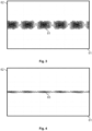
- Fig. 3 shows first measurement results in which the emission window of the laser sensor module 100 was covered by a white tape inhibiting measurement of particle densities.
- the laser sensor module 100 comprising three lasers 111 and corresponding detectors 121 was integrated in a mobile communication device 190.
- a mechanical stimulator 194 comprised by the mobile communication device 190 was used to provide mechanical excitation of the laser sensor module 100.
- Fig. 3 shows the signal amplitude 62 in arbitrary units as a function of time 61 of the indication signal 81 caused by the white tape of one single laser 111 and corresponding detector 121.
- the repetition time of sinusoidal movement of the emission window is about 8 ms.
- the Doppler frequency of the indication signal 81 goes to 0 Hz.
- Fig. 3 shows that for white tape, giving large back reflections, the Doppler signals are easily detected.
- the amplitude is approximately 8 ⁇ m.
- Fig. 4 shows second measurement results caused by a fingerprint on the cover glass of the mobile communication device 190 which builds the emission window 145 of the laser sensor module 100.
- the indication signal 83 caused by the fingerprint is smaller than the indication signal 81 caused by the white tape discussed above, as expected.
- the indication signal 83 is still easily detectable to enable a quantitative measure of the soiling of the emission window 145 (fingerprint).
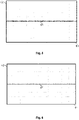
- Fig. 5 shows third measurement results in which the emission window 145 is cleaned but the mechanical excitation by means of the mechanical stimulator 194 is still provided.
- the measurement signal 85 shows that minor signals are still present and when looking carefully, distortion from the sinusoidal patterns is still visible. These signals may be caused by a combination of minor reflections from the emission window 145 (scratches, inclusions, imperfections) in combination with interference effects of some light which is retro-reflecting to the laser 111 via the emission window 145 and a PCB used for mounting and connecting the laser 111 and detector 121. Soiling of the emission window 145 by means of, for example, a fingerprint results in a frequency fD, while the light coming back from the PCB results in a frequency 2fD because the distance variation is doubled in this case.
- Fig. 6 shows fourth measurement results in which the mechanical stimulator 194 is switched off.
- the signal without mechanical excitation 87 shows the noise floor level of the laser sensor module. The same signal is observed when the mechanical stimulator 194 is switched on and the emission window is removed, as expected.
- a measure is obtained for the soiling of the emission window 145.
- this measure is above a certain threshold, the user can be warned.
- This measure for soiling of the emission window 145 can also be used to make a correction of the measured PM 2.5 value to an estimated real value as discussed above.
- a laser sensor module 100 comprising more than one laser 111 and detector 121 (measurement channel) the correlation between the signals of a multi-channel (typically 3 measurement channels) laser sensor module 100 can be used to identify whether the emission window 145 (e.g. cover glass) contains contamination.
- the emission window 145 e.g. cover glass
- the signals of each detector 121 are uncorrelated, as each measurement channel has its own noise statistic and the same particle 10 is because of the inclination between the laser beams 112 never seen by two or more detectors simultaneously, hence the measurement signals are uncorrelated.
- the signals are correlated. This can be used to distinguish indication signals caused by soiling of the emission window 145 from real particle signals. Simple recursive algorithms and more sophisticated FFT based signal processing algorithms can be used to estimate the correlation, hence providing a qualitative and especially quantitative measure of the soiling of the emission window.
- Periodic components caused by the mechanical stimulator 160, 194 may be suppressed by means of signal processing.
- an adaptive filter that is configured as an adaptive periodic interference canceller could be used, which models the periodic components such as shown in Fig. 4 and cancels the slowly varying constant periodic components from the indication signal.
- the coefficients in this canceller can also be used to realize a fingerprint detector.
- Advantage of using such a canceller is that the particle detection can continue during mechanical stimulation of the emission window 145.
- the indication signal can therefore be used in a first step to provide quantitative measure of the soiling of the emission window 145 and in a second step after filtering the periodic components caused by mechanical stimulation to determine the particle density.
- Fig. 7 shows a principal sketch of a mobile communication device 190 comprising a laser sensor module 100.
- the laser sensor module 100 is adapted to emit a laser beam 112.
- the mobile communication device 190 comprises a user interface 191, a main processing device 192 and a main memory device 193.
- the main processing device 192 is connected with the main memory device 193 and with the laser sensor module 100.
- the main processing device 192 comprises at least a part of the functionalities of the evaluator 150 which are described above.
- the main processing device 192 stores data related to particle detection in the main memory device 193.
- the main processing device 192 and the main memory device 193 are only used to prepare or adapt data provided by means of the laser sensor module 100 such that the data can be presented to a user of the mobile communication device 190 by means of user interface 191.
- the laser sensor module 100 may be powered by means of a power supply of the mobile communication device 190.
- the mobile communication device 190 further comprises a mechanical stimulator 194.
- the mechanical stimulator 194 is in this case a loudspeaker of the mobile communication device 190.
- the loudspeaker provides a mechanical excitation of the emission window (not shown) at a predefined frequency (e.g. resonance frequency of the emission window).
- the main processing device 192 is arranged to determine a soiling of the emission window during mechanical excitation by means on an indication signal provided by the laser sensor module 100 as described above.
- the main processing device 192 is further arranged to calculate and to correct the particle density based on the indication signal or to initiate an error signal.
- An air cleaner or ventilation hood may, for example, comprise the laser sensor module 100.
- the fan of, for example, the air cleaner may be used to (automatically) excite the emission window.
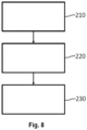
- Fig. 8 shows a principal sketch of a method of testing a soiling of an emission window 145 of a laser sensor module 100.
- a laser beam 112 is emitted through an emission window 145 to a focus region.
- a mechanical excitation of the emission window 145 is provided during emission of the laser beam 112.
- An interference signal especially a self-mixing interference signal is determined in step 230 during mechanical excitation of the emission window 145.
Landscapes
- Chemical & Material Sciences (AREA)
- Biochemistry (AREA)
- General Physics & Mathematics (AREA)
- Health & Medical Sciences (AREA)
- Life Sciences & Earth Sciences (AREA)
- Analytical Chemistry (AREA)
- Pathology (AREA)
- General Health & Medical Sciences (AREA)
- Physics & Mathematics (AREA)
- Immunology (AREA)
- Dispersion Chemistry (AREA)
- Engineering & Computer Science (AREA)
- Signal Processing (AREA)
- Investigating Or Analysing Materials By Optical Means (AREA)
- Investigating, Analyzing Materials By Fluorescence Or Luminescence (AREA)
Claims (14)
- Module capteur laser (100) pour mesurer une densité particulaire de particules (10) dont la taille est inférieure à 20 µm, de préférence inférieure à 10 µm, dans un fluide, le module capteur laser (100) comprenant un laser (111), un détecteur (121) et un agencement optique (140) pour focaliser le faisceau laser sur une zone de focalisation, le laser (111) étant conçu pour émettre un faisceau laser (112) au travers de l'agencement optique (140) jusqu'à la zone de focalisation, l'agencement optique comprenant une fenêtre d'émission (145), caractérisé en ce que le détecteur (121) est conçu pour déterminer un signal d'interférence d'une interférence de la lumière laser réfléchie avec la lumière laser émise, le module capteur laser (100) étant conçu pour fournir un signal d'indication d'une contamination de la fenêtre d'émission (145) sur la base d'un signal d'interférence déterminé au cours d'une excitation mécanique de la fenêtre d'émission (145).
- Module capteur laser (100) selon la revendication 1, le signal d'interférence étant un signal d'interférence à auto-mélange, le module capteur laser (100) comprenant un évaluateur (150), l'évaluateur (150) étant conçu pour déterminer la contamination de la fenêtre d'émission (145) sur la base du signal d'interférence à auto-mélange déterminé au cours de l'excitation mécanique de la fenêtre d'émission (145), et le module capteur laser (100) étant conçu pour générer le signal d'indication de la contamination de la fenêtre d'émission (145) après la détermination de la contamination de la fenêtre d'émission (145).
- Module capteur laser (100) selon l'une quelconque des revendications 1 ou 2, le signal d'indication permettant la détermination d'une mesure quantitative de la contamination.
- Module capteur laser (100) selon la revendication 3, le module capteur laser (100) étant conçu pour corriger une densité particulaire mesurée sur la base de la mesure quantitative déterminée de la contamination.
- Module capteur laser (100) selon l'une quelconque des revendications précédentes, le module capteur laser (100) comprenant un stimulateur mécanique (160), et le stimulateur mécanique (160) étant conçu pour exciter mécaniquement la fenêtre d'émission (145) dès réception d'un signal de commande d'excitation.
- Dispositif comprenant le module capteur laser (100) selon l'une quelconque des revendications précédentes, le dispositif comprenant un indicateur, l'indicateur étant conçu pour fournir une indication de la contamination à un utilisateur du dispositif sur la base du signal d'indication.
- Dispositif selon la revendication 6, le dispositif étant conçu pour amorcer l'excitation mécanique de la fenêtre d'émission (145).
- Dispositif selon la revendication 6 ou 7, le dispositif étant conçu pour déterminer la contamination de la fenêtre d'émission (145) sur la base du signal d'interférence déterminé au cours de l'excitation mécanique de la fenêtre d'émission (145).
- Dispositif selon la revendication 6 à 8, le dispositif étant conçu pour présenter une densité particulaire corrigée sur la base du signal d'indication.
- Dispositif selon la revendication 9, le dispositif étant conçu pour déterminer une mesure quantitative de contamination sur la base du signal d'indication, et le dispositif étant conçu pour corriger une densité particulaire mesurée sur la base de la mesure quantitative déterminée de la contamination.
- Dispositif selon l'une quelconque des revendications 6 à 10, le dispositif comprenant un stimulateur mécanique (194), le dispositif étant conçu pour amorcer l'excitation mécanique de la fenêtre d'émission (145) au moyen du stimulateur mécanique (194), et le dispositif étant conçu pour recevoir le signal d'interférence déterminé au cours de l'excitation mécanique de la fenêtre d'émission (145) depuis le module capteur laser (100).
- Dispositif selon l'une quelconque des revendications 6 à 11, le dispositif étant un dispositif de communication mobile (190).
- Procédé de test d'une contamination d'une fenêtre d'émission d'un module capteur laser (100) pour mesurer une densité particulaire de particules (10) dont la taille est inférieure à 20 µm, de préférence inférieure à 10 µm, dans un fluide, le procédé comprenant les étapes suivantes :émission d'un faisceau laser (112) au travers d'une fenêtre d'émission (145) jusqu'à une zone de focalisation,excitation mécanique de la fenêtre d'émission (145) au cours de l'émission du faisceau laser (112),détermination d'un signal d'interférence d'une interférence de la lumière laser réfléchie avec la lumière laser émise au cours de l'excitation mécanique de la fenêtre d'émission (145), etfourniture d'un signal d'indication de la contamination de la fenêtre d'émission (145) sur la base du signal d'interférence déterminé au cours de l'excitation mécanique de la fenêtre d'émission (145).
- Produit-programme d'ordinateur comprenant des instructions pour amener le module capteur laser (100) selon l'une quelconque des revendications 1 à 5 à exécuter les étapes du procédé selon la revendication 13.
Applications Claiming Priority (2)
| Application Number | Priority Date | Filing Date | Title |
|---|---|---|---|
| EP18179090.8A EP3588055A1 (fr) | 2018-06-21 | 2018-06-21 | Module de capteur laser avec indication de disponibilité pour utilisation |
| PCT/EP2019/065445 WO2019243149A1 (fr) | 2018-06-21 | 2019-06-13 | Module de capteur laser avec indication de disponibilité pour utilisation |
Publications (2)
| Publication Number | Publication Date |
|---|---|
| EP3811053A1 EP3811053A1 (fr) | 2021-04-28 |
| EP3811053B1 true EP3811053B1 (fr) | 2023-02-15 |
Family
ID=62748837
Family Applications (2)
| Application Number | Title | Priority Date | Filing Date |
|---|---|---|---|
| EP18179090.8A Withdrawn EP3588055A1 (fr) | 2018-06-21 | 2018-06-21 | Module de capteur laser avec indication de disponibilité pour utilisation |
| EP19729304.6A Active EP3811053B1 (fr) | 2018-06-21 | 2019-06-13 | Module de capteur laser pour la mesure de densité de particules comprenant détecteur apte à émettre un signal indiquant la pollution d'une fénetre d'émission, procédé et programme informatique |
Family Applications Before (1)
| Application Number | Title | Priority Date | Filing Date |
|---|---|---|---|
| EP18179090.8A Withdrawn EP3588055A1 (fr) | 2018-06-21 | 2018-06-21 | Module de capteur laser avec indication de disponibilité pour utilisation |
Country Status (4)
| Country | Link |
|---|---|
| US (1) | US11441998B2 (fr) |
| EP (2) | EP3588055A1 (fr) |
| CN (1) | CN112639438B (fr) |
| WO (1) | WO2019243149A1 (fr) |
Families Citing this family (1)
| Publication number | Priority date | Publication date | Assignee | Title |
|---|---|---|---|---|
| US11442003B2 (en) * | 2020-09-23 | 2022-09-13 | Radiant Innovation Inc. | Maintenance method of gas detecting device |
Family Cites Families (25)
| Publication number | Priority date | Publication date | Assignee | Title |
|---|---|---|---|---|
| US4871251A (en) * | 1987-04-27 | 1989-10-03 | Preikschat F K | Apparatus and method for particle analysis |
| SE465338B (sv) * | 1990-01-05 | 1991-08-26 | Abb Stal Ab | Saett och anordning foer detektering av partiklar i stroemmande medier |
| WO2002037410A1 (fr) | 2000-11-06 | 2002-05-10 | Koninklijke Philips Electronics N.V. | Procede de mesure du mouvement d'un dispositif de saisie |
| EP1256793A1 (fr) * | 2001-05-11 | 2002-11-13 | WTW Wissenschaftlich-Technische Werkstätten GmbH & Co. KG | Dispositif pour la mesure optique dans un milieu |
| SG115621A1 (en) * | 2003-02-24 | 2005-10-28 | Asml Netherlands Bv | Method and device for measuring contamination of a surface of a component of a lithographic apparatus |
| CA2883638C (fr) * | 2004-11-12 | 2017-06-20 | Xtralis Technologies Ltd | Detecteur de particules, systeme et procede |
| JP2007022877A (ja) * | 2005-07-20 | 2007-02-01 | Sumitomo Electric Ind Ltd | ガラス微粒子堆積体の製造方法 |
| JP4833687B2 (ja) * | 2006-02-27 | 2011-12-07 | 株式会社日立ハイテクノロジーズ | プラズマ処理装置 |
| JP5032836B2 (ja) * | 2006-12-21 | 2012-09-26 | 株式会社堀場製作所 | オイルミスト検出装置 |
| US9869689B2 (en) * | 2009-04-29 | 2018-01-16 | Koninklijke Philips Electronics N.V. | Laser diode based multiple-beam laser spot imaging system for characterization of vehicle dynamics |
| DE102010055428A1 (de) * | 2010-12-21 | 2012-06-21 | Giesecke & Devrient Gmbh | Verschmutzungsprüfung des Fensters einer Messvorrichtung zur Prüfung von Blattgut |
| CN102445458B (zh) * | 2011-10-18 | 2013-07-31 | 中国科学院合肥物质科学研究院 | 一种光学透镜测污装置 |
| DE102011116487A1 (de) * | 2011-10-20 | 2013-04-25 | Giesecke & Devrient Gmbh | Verschmutzungsprüfung des Fensters einer Messvorrichtung |
| DE102013100443A1 (de) * | 2012-08-14 | 2014-05-15 | Carl Zeiss Microscopy Gmbh | Schutzfenstervorrichtung für eine Beschichtungsanlage |
| DE102015207289B4 (de) | 2015-04-22 | 2025-12-24 | Robert Bosch Gmbh | Partikelsensorvorrichtung |
| RU2716878C2 (ru) * | 2015-07-30 | 2020-03-17 | Конинклейке Филипс Н.В. | Лазерный датчик для обнаружения плотности частиц |
| EP3329250B1 (fr) * | 2015-07-30 | 2018-12-26 | Koninklijke Philips N.V. | Capteur laser pour détection de taille de particules |
| WO2017060105A1 (fr) * | 2015-10-08 | 2017-04-13 | Koninklijke Philips N.V. | Capteur de particules pour détection de particules |
| CN105772961A (zh) * | 2016-03-29 | 2016-07-20 | 同高先进制造科技(太仓)有限公司 | 基于散射光检测激光头保护镜片污染监控装置及工作方法 |
| CN105891416B (zh) * | 2016-03-31 | 2018-11-09 | 南京航空航天大学 | 超声辅助流体中污染物高感度检测系统及其工作方法 |
| CN105911060B (zh) * | 2016-04-20 | 2018-08-21 | 北京视程科技有限公司 | 一种透射式视程能见度仪窗镜污染的可视化检测方法和装置 |
| WO2017198555A1 (fr) * | 2016-05-19 | 2017-11-23 | Koninklijke Philips N.V. | Capteur laser destiné à la détection de particules |
| US11237387B2 (en) * | 2016-12-05 | 2022-02-01 | Texas Instruments Incorporated | Ultrasonic lens cleaning system with foreign material detection |
| CN106645197B (zh) * | 2016-12-29 | 2024-01-30 | 中国工程物理研究院激光聚变研究中心 | 检测精密光学元件表面颗粒物的在线检测系统及应用方法 |
| EP3401664A1 (fr) * | 2017-05-12 | 2018-11-14 | Koninklijke Philips N.V. | Procédé de suppression de faux signaux positifs pendant la détection de particules d'interférence à mélange automatique |
-
2018
- 2018-06-21 EP EP18179090.8A patent/EP3588055A1/fr not_active Withdrawn
-
2019
- 2019-06-13 WO PCT/EP2019/065445 patent/WO2019243149A1/fr not_active Ceased
- 2019-06-13 EP EP19729304.6A patent/EP3811053B1/fr active Active
- 2019-06-13 CN CN201980041649.9A patent/CN112639438B/zh active Active
-
2020
- 2020-12-18 US US17/126,060 patent/US11441998B2/en active Active
Also Published As
| Publication number | Publication date |
|---|---|
| WO2019243149A1 (fr) | 2019-12-26 |
| CN112639438A (zh) | 2021-04-09 |
| EP3811053A1 (fr) | 2021-04-28 |
| EP3588055A1 (fr) | 2020-01-01 |
| US11441998B2 (en) | 2022-09-13 |
| US20210148807A1 (en) | 2021-05-20 |
| CN112639438B (zh) | 2023-07-28 |
Similar Documents
| Publication | Publication Date | Title |
|---|---|---|
| US11054244B2 (en) | Method of suppressing false positive signals during self mixing interference particle detection | |
| US11187643B2 (en) | Laser sensor module for particle density detection | |
| US12436247B2 (en) | Laser sensor module with soiling detection | |
| EP3551993B1 (fr) | Module de capteur optique de particules | |
| CN101952863B (zh) | 借助于两种光谱不同的散射光测量的烟雾探测 | |
| EP3329250B1 (fr) | Capteur laser pour détection de taille de particules | |
| EP3225977B1 (fr) | Procédé et système de capteur pour la détection de particules | |
| JP7481507B2 (ja) | ライダーセンサの保護スクリーンの汚れを識別する方法及び装置 | |
| US11441998B2 (en) | Laser sensor module with indication of readiness for use | |
| US20220412794A1 (en) | Apparatus for Monitoring Mechanical Integrity of an Eye-safety Component of an Illuminator | |
| EP4065938B1 (fr) | Appareil de surveillance d'intégrité mécanique d'un élément de sécurité oculaire d'un illuminateur | |
| US20080192229A1 (en) | Relative Movement Sensor Comprising Multiple Lasers | |
| KR102652916B1 (ko) | 분포형 광섬유 음향센서 및 그 음향측정방법 | |
| JPH07146354A (ja) | 距離測定装置 | |
| KR20250054367A (ko) | 라이다 센서의 윈도우 오염 검출 장치 및 방법 | |
| CN119620884A (zh) | 具有背光的超声波触摸传感器 |
Legal Events
| Date | Code | Title | Description |
|---|---|---|---|
| STAA | Information on the status of an ep patent application or granted ep patent |
Free format text: STATUS: UNKNOWN |
|
| STAA | Information on the status of an ep patent application or granted ep patent |
Free format text: STATUS: THE INTERNATIONAL PUBLICATION HAS BEEN MADE |
|
| PUAI | Public reference made under article 153(3) epc to a published international application that has entered the european phase |
Free format text: ORIGINAL CODE: 0009012 |
|
| STAA | Information on the status of an ep patent application or granted ep patent |
Free format text: STATUS: REQUEST FOR EXAMINATION WAS MADE |
|
| 17P | Request for examination filed |
Effective date: 20201123 |
|
| AK | Designated contracting states |
Kind code of ref document: A1 Designated state(s): AL AT BE BG CH CY CZ DE DK EE ES FI FR GB GR HR HU IE IS IT LI LT LU LV MC MK MT NL NO PL PT RO RS SE SI SK SM TR |
|
| AX | Request for extension of the european patent |
Extension state: BA ME |
|
| RAP1 | Party data changed (applicant data changed or rights of an application transferred) |
Owner name: TRUMPF PHOTONIC COMPONENTS GMBH Owner name: ROBERT BOSCH GMBH |
|
| DAV | Request for validation of the european patent (deleted) | ||
| DAX | Request for extension of the european patent (deleted) | ||
| GRAP | Despatch of communication of intention to grant a patent |
Free format text: ORIGINAL CODE: EPIDOSNIGR1 |
|
| STAA | Information on the status of an ep patent application or granted ep patent |
Free format text: STATUS: GRANT OF PATENT IS INTENDED |
|
| INTG | Intention to grant announced |
Effective date: 20220906 |
|
| GRAS | Grant fee paid |
Free format text: ORIGINAL CODE: EPIDOSNIGR3 |
|
| GRAA | (expected) grant |
Free format text: ORIGINAL CODE: 0009210 |
|
| STAA | Information on the status of an ep patent application or granted ep patent |
Free format text: STATUS: THE PATENT HAS BEEN GRANTED |
|
| AK | Designated contracting states |
Kind code of ref document: B1 Designated state(s): AL AT BE BG CH CY CZ DE DK EE ES FI FR GB GR HR HU IE IS IT LI LT LU LV MC MK MT NL NO PL PT RO RS SE SI SK SM TR |
|
| REG | Reference to a national code |
Ref country code: CH Ref legal event code: EP Ref country code: GB Ref legal event code: FG4D |
|
| REG | Reference to a national code |
Ref country code: DE Ref legal event code: R096 Ref document number: 602019025289 Country of ref document: DE |
|
| REG | Reference to a national code |
Ref country code: AT Ref legal event code: REF Ref document number: 1548460 Country of ref document: AT Kind code of ref document: T Effective date: 20230315 Ref country code: IE Ref legal event code: FG4D |
|
| REG | Reference to a national code |
Ref country code: LT Ref legal event code: MG9D |
|
| REG | Reference to a national code |
Ref country code: NL Ref legal event code: MP Effective date: 20230215 |
|
| REG | Reference to a national code |
Ref country code: AT Ref legal event code: MK05 Ref document number: 1548460 Country of ref document: AT Kind code of ref document: T Effective date: 20230215 |
|
| PG25 | Lapsed in a contracting state [announced via postgrant information from national office to epo] |
Ref country code: RS Free format text: LAPSE BECAUSE OF FAILURE TO SUBMIT A TRANSLATION OF THE DESCRIPTION OR TO PAY THE FEE WITHIN THE PRESCRIBED TIME-LIMIT Effective date: 20230215 Ref country code: PT Free format text: LAPSE BECAUSE OF FAILURE TO SUBMIT A TRANSLATION OF THE DESCRIPTION OR TO PAY THE FEE WITHIN THE PRESCRIBED TIME-LIMIT Effective date: 20230615 Ref country code: NO Free format text: LAPSE BECAUSE OF FAILURE TO SUBMIT A TRANSLATION OF THE DESCRIPTION OR TO PAY THE FEE WITHIN THE PRESCRIBED TIME-LIMIT Effective date: 20230515 Ref country code: NL Free format text: LAPSE BECAUSE OF FAILURE TO SUBMIT A TRANSLATION OF THE DESCRIPTION OR TO PAY THE FEE WITHIN THE PRESCRIBED TIME-LIMIT Effective date: 20230215 Ref country code: LV Free format text: LAPSE BECAUSE OF FAILURE TO SUBMIT A TRANSLATION OF THE DESCRIPTION OR TO PAY THE FEE WITHIN THE PRESCRIBED TIME-LIMIT Effective date: 20230215 Ref country code: LT Free format text: LAPSE BECAUSE OF FAILURE TO SUBMIT A TRANSLATION OF THE DESCRIPTION OR TO PAY THE FEE WITHIN THE PRESCRIBED TIME-LIMIT Effective date: 20230215 Ref country code: HR Free format text: LAPSE BECAUSE OF FAILURE TO SUBMIT A TRANSLATION OF THE DESCRIPTION OR TO PAY THE FEE WITHIN THE PRESCRIBED TIME-LIMIT Effective date: 20230215 Ref country code: ES Free format text: LAPSE BECAUSE OF FAILURE TO SUBMIT A TRANSLATION OF THE DESCRIPTION OR TO PAY THE FEE WITHIN THE PRESCRIBED TIME-LIMIT Effective date: 20230215 Ref country code: AT Free format text: LAPSE BECAUSE OF FAILURE TO SUBMIT A TRANSLATION OF THE DESCRIPTION OR TO PAY THE FEE WITHIN THE PRESCRIBED TIME-LIMIT Effective date: 20230215 |
|
| PG25 | Lapsed in a contracting state [announced via postgrant information from national office to epo] |
Ref country code: SE Free format text: LAPSE BECAUSE OF FAILURE TO SUBMIT A TRANSLATION OF THE DESCRIPTION OR TO PAY THE FEE WITHIN THE PRESCRIBED TIME-LIMIT Effective date: 20230215 Ref country code: PL Free format text: LAPSE BECAUSE OF FAILURE TO SUBMIT A TRANSLATION OF THE DESCRIPTION OR TO PAY THE FEE WITHIN THE PRESCRIBED TIME-LIMIT Effective date: 20230215 Ref country code: IS Free format text: LAPSE BECAUSE OF FAILURE TO SUBMIT A TRANSLATION OF THE DESCRIPTION OR TO PAY THE FEE WITHIN THE PRESCRIBED TIME-LIMIT Effective date: 20230615 Ref country code: GR Free format text: LAPSE BECAUSE OF FAILURE TO SUBMIT A TRANSLATION OF THE DESCRIPTION OR TO PAY THE FEE WITHIN THE PRESCRIBED TIME-LIMIT Effective date: 20230516 Ref country code: FI Free format text: LAPSE BECAUSE OF FAILURE TO SUBMIT A TRANSLATION OF THE DESCRIPTION OR TO PAY THE FEE WITHIN THE PRESCRIBED TIME-LIMIT Effective date: 20230215 |
|
| PG25 | Lapsed in a contracting state [announced via postgrant information from national office to epo] |
Ref country code: SM Free format text: LAPSE BECAUSE OF FAILURE TO SUBMIT A TRANSLATION OF THE DESCRIPTION OR TO PAY THE FEE WITHIN THE PRESCRIBED TIME-LIMIT Effective date: 20230215 Ref country code: RO Free format text: LAPSE BECAUSE OF FAILURE TO SUBMIT A TRANSLATION OF THE DESCRIPTION OR TO PAY THE FEE WITHIN THE PRESCRIBED TIME-LIMIT Effective date: 20230215 Ref country code: EE Free format text: LAPSE BECAUSE OF FAILURE TO SUBMIT A TRANSLATION OF THE DESCRIPTION OR TO PAY THE FEE WITHIN THE PRESCRIBED TIME-LIMIT Effective date: 20230215 Ref country code: DK Free format text: LAPSE BECAUSE OF FAILURE TO SUBMIT A TRANSLATION OF THE DESCRIPTION OR TO PAY THE FEE WITHIN THE PRESCRIBED TIME-LIMIT Effective date: 20230215 Ref country code: CZ Free format text: LAPSE BECAUSE OF FAILURE TO SUBMIT A TRANSLATION OF THE DESCRIPTION OR TO PAY THE FEE WITHIN THE PRESCRIBED TIME-LIMIT Effective date: 20230215 |
|
| REG | Reference to a national code |
Ref country code: DE Ref legal event code: R097 Ref document number: 602019025289 Country of ref document: DE |
|
| PG25 | Lapsed in a contracting state [announced via postgrant information from national office to epo] |
Ref country code: SK Free format text: LAPSE BECAUSE OF FAILURE TO SUBMIT A TRANSLATION OF THE DESCRIPTION OR TO PAY THE FEE WITHIN THE PRESCRIBED TIME-LIMIT Effective date: 20230215 |
|
| PLBE | No opposition filed within time limit |
Free format text: ORIGINAL CODE: 0009261 |
|
| STAA | Information on the status of an ep patent application or granted ep patent |
Free format text: STATUS: NO OPPOSITION FILED WITHIN TIME LIMIT |
|
| PG25 | Lapsed in a contracting state [announced via postgrant information from national office to epo] |
Ref country code: MC Free format text: LAPSE BECAUSE OF FAILURE TO SUBMIT A TRANSLATION OF THE DESCRIPTION OR TO PAY THE FEE WITHIN THE PRESCRIBED TIME-LIMIT Effective date: 20230215 |
|
| 26N | No opposition filed |
Effective date: 20231116 |
|
| PG25 | Lapsed in a contracting state [announced via postgrant information from national office to epo] |
Ref country code: SI Free format text: LAPSE BECAUSE OF FAILURE TO SUBMIT A TRANSLATION OF THE DESCRIPTION OR TO PAY THE FEE WITHIN THE PRESCRIBED TIME-LIMIT Effective date: 20230215 Ref country code: MC Free format text: LAPSE BECAUSE OF FAILURE TO SUBMIT A TRANSLATION OF THE DESCRIPTION OR TO PAY THE FEE WITHIN THE PRESCRIBED TIME-LIMIT Effective date: 20230215 |
|
| REG | Reference to a national code |
Ref country code: CH Ref legal event code: PL |
|
| REG | Reference to a national code |
Ref country code: BE Ref legal event code: MM Effective date: 20230630 |
|
| GBPC | Gb: european patent ceased through non-payment of renewal fee |
Effective date: 20230613 |
|
| PG25 | Lapsed in a contracting state [announced via postgrant information from national office to epo] |
Ref country code: LU Free format text: LAPSE BECAUSE OF NON-PAYMENT OF DUE FEES Effective date: 20230613 |
|
| REG | Reference to a national code |
Ref country code: IE Ref legal event code: MM4A |
|
| PG25 | Lapsed in a contracting state [announced via postgrant information from national office to epo] |
Ref country code: LU Free format text: LAPSE BECAUSE OF NON-PAYMENT OF DUE FEES Effective date: 20230613 |
|
| PG25 | Lapsed in a contracting state [announced via postgrant information from national office to epo] |
Ref country code: IE Free format text: LAPSE BECAUSE OF NON-PAYMENT OF DUE FEES Effective date: 20230613 |
|
| PG25 | Lapsed in a contracting state [announced via postgrant information from national office to epo] |
Ref country code: IE Free format text: LAPSE BECAUSE OF NON-PAYMENT OF DUE FEES Effective date: 20230613 Ref country code: CH Free format text: LAPSE BECAUSE OF NON-PAYMENT OF DUE FEES Effective date: 20230630 Ref country code: GB Free format text: LAPSE BECAUSE OF NON-PAYMENT OF DUE FEES Effective date: 20230613 |
|
| PG25 | Lapsed in a contracting state [announced via postgrant information from national office to epo] |
Ref country code: IT Free format text: LAPSE BECAUSE OF FAILURE TO SUBMIT A TRANSLATION OF THE DESCRIPTION OR TO PAY THE FEE WITHIN THE PRESCRIBED TIME-LIMIT Effective date: 20230215 Ref country code: FR Free format text: LAPSE BECAUSE OF NON-PAYMENT OF DUE FEES Effective date: 20230630 Ref country code: BE Free format text: LAPSE BECAUSE OF NON-PAYMENT OF DUE FEES Effective date: 20230630 |
|
| PG25 | Lapsed in a contracting state [announced via postgrant information from national office to epo] |
Ref country code: BG Free format text: LAPSE BECAUSE OF FAILURE TO SUBMIT A TRANSLATION OF THE DESCRIPTION OR TO PAY THE FEE WITHIN THE PRESCRIBED TIME-LIMIT Effective date: 20230215 |
|
| PG25 | Lapsed in a contracting state [announced via postgrant information from national office to epo] |
Ref country code: BG Free format text: LAPSE BECAUSE OF FAILURE TO SUBMIT A TRANSLATION OF THE DESCRIPTION OR TO PAY THE FEE WITHIN THE PRESCRIBED TIME-LIMIT Effective date: 20230215 |
|
| PGFP | Annual fee paid to national office [announced via postgrant information from national office to epo] |
Ref country code: DE Payment date: 20250618 Year of fee payment: 7 |
|
| PG25 | Lapsed in a contracting state [announced via postgrant information from national office to epo] |
Ref country code: CY Free format text: LAPSE BECAUSE OF FAILURE TO SUBMIT A TRANSLATION OF THE DESCRIPTION OR TO PAY THE FEE WITHIN THE PRESCRIBED TIME-LIMIT; INVALID AB INITIO Effective date: 20190613 |
|
| PG25 | Lapsed in a contracting state [announced via postgrant information from national office to epo] |
Ref country code: HU Free format text: LAPSE BECAUSE OF FAILURE TO SUBMIT A TRANSLATION OF THE DESCRIPTION OR TO PAY THE FEE WITHIN THE PRESCRIBED TIME-LIMIT; INVALID AB INITIO Effective date: 20190613 |
|
| PG25 | Lapsed in a contracting state [announced via postgrant information from national office to epo] |
Ref country code: TR Free format text: LAPSE BECAUSE OF FAILURE TO SUBMIT A TRANSLATION OF THE DESCRIPTION OR TO PAY THE FEE WITHIN THE PRESCRIBED TIME-LIMIT Effective date: 20230215 |