EP3811078B1 - Procédé et dispositif de dosage de l'interaction et de la dynamique de perméation d'une molécule et d'une bicouche lipidique - Google Patents
Procédé et dispositif de dosage de l'interaction et de la dynamique de perméation d'une molécule et d'une bicouche lipidique Download PDFInfo
- Publication number
- EP3811078B1 EP3811078B1 EP19733408.9A EP19733408A EP3811078B1 EP 3811078 B1 EP3811078 B1 EP 3811078B1 EP 19733408 A EP19733408 A EP 19733408A EP 3811078 B1 EP3811078 B1 EP 3811078B1
- Authority
- EP
- European Patent Office
- Prior art keywords
- bilayer
- molecule
- plasmonic
- microcavity
- metal
- Prior art date
- Legal status (The legal status is an assumption and is not a legal conclusion. Google has not performed a legal analysis and makes no representation as to the accuracy of the status listed.)
- Active
Links
Images




Classifications
-
- G—PHYSICS
- G01—MEASURING; TESTING
- G01N—INVESTIGATING OR ANALYSING MATERIALS BY DETERMINING THEIR CHEMICAL OR PHYSICAL PROPERTIES
- G01N33/00—Investigating or analysing materials by specific methods not covered by groups G01N1/00 - G01N31/00
- G01N33/48—Biological material, e.g. blood, urine; Haemocytometers
- G01N33/50—Chemical analysis of biological material, e.g. blood, urine; Testing involving biospecific ligand binding methods; Immunological testing
- G01N33/53—Immunoassay; Biospecific binding assay; Materials therefor
- G01N33/543—Immunoassay; Biospecific binding assay; Materials therefor with an insoluble carrier for immobilising immunochemicals
- G01N33/54313—Immunoassay; Biospecific binding assay; Materials therefor with an insoluble carrier for immobilising immunochemicals the carrier being characterised by its particulate form
- G01N33/5432—Liposomes or microcapsules
-
- B—PERFORMING OPERATIONS; TRANSPORTING
- B01—PHYSICAL OR CHEMICAL PROCESSES OR APPARATUS IN GENERAL
- B01L—CHEMICAL OR PHYSICAL LABORATORY APPARATUS FOR GENERAL USE
- B01L3/00—Containers or dishes for laboratory use, e.g. laboratory glassware; Droppers
- B01L3/50—Containers for the purpose of retaining a material to be analysed, e.g. test tubes
- B01L3/502—Containers for the purpose of retaining a material to be analysed, e.g. test tubes with fluid transport, e.g. in multi-compartment structures
- B01L3/5027—Containers for the purpose of retaining a material to be analysed, e.g. test tubes with fluid transport, e.g. in multi-compartment structures by integrated microfluidic structures, i.e. dimensions of channels and chambers are such that surface tension forces are important, e.g. lab-on-a-chip
-
- B—PERFORMING OPERATIONS; TRANSPORTING
- B01—PHYSICAL OR CHEMICAL PROCESSES OR APPARATUS IN GENERAL
- B01L—CHEMICAL OR PHYSICAL LABORATORY APPARATUS FOR GENERAL USE
- B01L3/00—Containers or dishes for laboratory use, e.g. laboratory glassware; Droppers
- B01L3/50—Containers for the purpose of retaining a material to be analysed, e.g. test tubes
- B01L3/502—Containers for the purpose of retaining a material to be analysed, e.g. test tubes with fluid transport, e.g. in multi-compartment structures
- B01L3/5027—Containers for the purpose of retaining a material to be analysed, e.g. test tubes with fluid transport, e.g. in multi-compartment structures by integrated microfluidic structures, i.e. dimensions of channels and chambers are such that surface tension forces are important, e.g. lab-on-a-chip
- B01L3/502707—Containers for the purpose of retaining a material to be analysed, e.g. test tubes with fluid transport, e.g. in multi-compartment structures by integrated microfluidic structures, i.e. dimensions of channels and chambers are such that surface tension forces are important, e.g. lab-on-a-chip characterised by the manufacture of the container or its components
-
- B—PERFORMING OPERATIONS; TRANSPORTING
- B01—PHYSICAL OR CHEMICAL PROCESSES OR APPARATUS IN GENERAL
- B01L—CHEMICAL OR PHYSICAL LABORATORY APPARATUS FOR GENERAL USE
- B01L3/00—Containers or dishes for laboratory use, e.g. laboratory glassware; Droppers
- B01L3/50—Containers for the purpose of retaining a material to be analysed, e.g. test tubes
- B01L3/502—Containers for the purpose of retaining a material to be analysed, e.g. test tubes with fluid transport, e.g. in multi-compartment structures
- B01L3/5027—Containers for the purpose of retaining a material to be analysed, e.g. test tubes with fluid transport, e.g. in multi-compartment structures by integrated microfluidic structures, i.e. dimensions of channels and chambers are such that surface tension forces are important, e.g. lab-on-a-chip
- B01L3/502715—Containers for the purpose of retaining a material to be analysed, e.g. test tubes with fluid transport, e.g. in multi-compartment structures by integrated microfluidic structures, i.e. dimensions of channels and chambers are such that surface tension forces are important, e.g. lab-on-a-chip characterised by interfacing components, e.g. fluidic, electrical, optical or mechanical interfaces
-
- G—PHYSICS
- G01—MEASURING; TESTING
- G01N—INVESTIGATING OR ANALYSING MATERIALS BY DETERMINING THEIR CHEMICAL OR PHYSICAL PROPERTIES
- G01N21/00—Investigating or analysing materials by the use of optical means, i.e. using sub-millimetre waves, infrared, visible or ultraviolet light
- G01N21/62—Systems in which the material investigated is excited whereby it emits light or causes a change in wavelength of the incident light
- G01N21/63—Systems in which the material investigated is excited whereby it emits light or causes a change in wavelength of the incident light optically excited
- G01N21/64—Fluorescence; Phosphorescence
- G01N21/6408—Fluorescence; Phosphorescence with measurement of decay time, time resolved fluorescence
-
- G—PHYSICS
- G01—MEASURING; TESTING
- G01N—INVESTIGATING OR ANALYSING MATERIALS BY DETERMINING THEIR CHEMICAL OR PHYSICAL PROPERTIES
- G01N21/00—Investigating or analysing materials by the use of optical means, i.e. using sub-millimetre waves, infrared, visible or ultraviolet light
- G01N21/62—Systems in which the material investigated is excited whereby it emits light or causes a change in wavelength of the incident light
- G01N21/63—Systems in which the material investigated is excited whereby it emits light or causes a change in wavelength of the incident light optically excited
- G01N21/64—Fluorescence; Phosphorescence
- G01N21/645—Specially adapted constructive features of fluorimeters
- G01N21/648—Specially adapted constructive features of fluorimeters using evanescent coupling or surface plasmon coupling for the excitation of fluorescence
-
- G—PHYSICS
- G01—MEASURING; TESTING
- G01N—INVESTIGATING OR ANALYSING MATERIALS BY DETERMINING THEIR CHEMICAL OR PHYSICAL PROPERTIES
- G01N21/00—Investigating or analysing materials by the use of optical means, i.e. using sub-millimetre waves, infrared, visible or ultraviolet light
- G01N21/62—Systems in which the material investigated is excited whereby it emits light or causes a change in wavelength of the incident light
- G01N21/63—Systems in which the material investigated is excited whereby it emits light or causes a change in wavelength of the incident light optically excited
- G01N21/65—Raman scattering
- G01N21/658—Raman scattering enhancement Raman, e.g. surface plasmons
-
- G—PHYSICS
- G01—MEASURING; TESTING
- G01N—INVESTIGATING OR ANALYSING MATERIALS BY DETERMINING THEIR CHEMICAL OR PHYSICAL PROPERTIES
- G01N33/00—Investigating or analysing materials by specific methods not covered by groups G01N1/00 - G01N31/00
- G01N33/48—Biological material, e.g. blood, urine; Haemocytometers
- G01N33/483—Physical analysis of biological material
- G01N33/487—Physical analysis of biological material of liquid biological material
- G01N33/48707—Physical analysis of biological material of liquid biological material by electrical means
- G01N33/48721—Investigating individual macromolecules, e.g. by translocation through nanopores
-
- B—PERFORMING OPERATIONS; TRANSPORTING
- B01—PHYSICAL OR CHEMICAL PROCESSES OR APPARATUS IN GENERAL
- B01L—CHEMICAL OR PHYSICAL LABORATORY APPARATUS FOR GENERAL USE
- B01L2200/00—Solutions for specific problems relating to chemical or physical laboratory apparatus
- B01L2200/06—Fluid handling related problems
- B01L2200/0647—Handling flowable solids, e.g. microscopic beads, cells, particles
- B01L2200/0668—Trapping microscopic beads
-
- B—PERFORMING OPERATIONS; TRANSPORTING
- B01—PHYSICAL OR CHEMICAL PROCESSES OR APPARATUS IN GENERAL
- B01L—CHEMICAL OR PHYSICAL LABORATORY APPARATUS FOR GENERAL USE
- B01L2300/00—Additional constructional details
- B01L2300/06—Auxiliary integrated devices, integrated components
- B01L2300/0627—Sensor or part of a sensor is integrated
- B01L2300/0654—Lenses; Optical fibres
-
- B—PERFORMING OPERATIONS; TRANSPORTING
- B01—PHYSICAL OR CHEMICAL PROCESSES OR APPARATUS IN GENERAL
- B01L—CHEMICAL OR PHYSICAL LABORATORY APPARATUS FOR GENERAL USE
- B01L2300/00—Additional constructional details
- B01L2300/08—Geometry, shape and general structure
- B01L2300/0809—Geometry, shape and general structure rectangular shaped
- B01L2300/0816—Cards, e.g. flat sample carriers usually with flow in two horizontal directions
-
- B—PERFORMING OPERATIONS; TRANSPORTING
- B01—PHYSICAL OR CHEMICAL PROCESSES OR APPARATUS IN GENERAL
- B01L—CHEMICAL OR PHYSICAL LABORATORY APPARATUS FOR GENERAL USE
- B01L2300/00—Additional constructional details
- B01L2300/08—Geometry, shape and general structure
- B01L2300/0809—Geometry, shape and general structure rectangular shaped
- B01L2300/0829—Multi-well plates; Microtitration plates
-
- G—PHYSICS
- G01—MEASURING; TESTING
- G01N—INVESTIGATING OR ANALYSING MATERIALS BY DETERMINING THEIR CHEMICAL OR PHYSICAL PROPERTIES
- G01N27/00—Investigating or analysing materials by the use of electric, electrochemical, or magnetic means
- G01N27/02—Investigating or analysing materials by the use of electric, electrochemical, or magnetic means by investigating impedance
- G01N27/026—Dielectric impedance spectroscopy
Definitions
- the present invention relates to a method of assaying permeation of a test molecule across a lipid bilayer.
- a key parameter in the pharmaceutical industry (which applies also across agrichemical and environmental and toxicological domains) is prediction of transmembrane (cell, plant prokaryotic or viral membrane) permeability of a given molecule or particle.
- transmembrane cell, plant prokaryotic or viral membrane
- many drugs have intracellular targets and thus transfer across the plasma membrane or intracellular membranes is required to elicit their response.
- cell membrane penetration by between 80 and 95% of commercial drugs is by passive diffusion there is much debate about the mechanism by which cells absorb drugs and other small molecules.
- QSAR quantitative structure-activity relationship
- PAMPA oil partitioning based parallel artificial membrane permeability assays
- IAM immobilised artificial membrane
- the former is an inadequate model of the cell membrane, the latter, slow and expensive to implement.
- cell culture or in-vivo models are widely used to evaluate drug transport, both are time-consuming and expensive.
- interpretation of results at a molecular level can be difficult because of the complexity of the cell and heterogeneity in cell populations. For example, where a drugs toxic effect originates from damage to membrane, such effects on membrane integrity are easier to identify in a model than a whole cell.
- WO2016/001391 describes a microfluidic device comprising a substrate having an array of concave microcavities with a metallic surface defining an aperture, a liquid disposed within the microcavity, a lipid bilayer suspended across the aperture, and a microfluidic channel containing a liquid disposed on top of the substrate in fluid communication with the lipid bilayer.
- WO2016/001391 also describes the use of the device to interrogate the lipid bilayer by electrochemical or fluorescence detection. The method is unable to provide any information on specific molecular interactions or lipid bilayer permeation data or permeation dynamics.
- Banerjee et al. (Chemical Physics Letters, Vol. 489, No. 1-3, 1 April 2010 ) describes a method of assaying a test molecule and a lipid bilayer by using a microfluidic device composed of a metallic substrate and the interaction of the test molecule with the lipid bilayer is detected by Raman spectroscopy.
- D1 uses nanopatterned substrates "to detect binding effects" of test molecules. D1 states that the nanopores are 20 nm in size and that the lipid bilayer is imbedded/incorporated in the substrate pores. This means that permeation of a test molecule is not possible as the bilayer is resting on the nanopatterned substrate, and there is no free space located beneath the lipid bilayer and as such the test molecule will remain stuck within the lipid bilayer.
- US2017/176449 describes a method of assaying a test molecule and a lipid bilayer by using a microfluidic device composed of a metallic substrate (gold) in which microwells are formed filled with a buffer in which the opening is spanned by a lipid bilayer.
- the method comprises monitoring the change of resistance of the lipid bilayer and correlates the change of resistance of the bilayer to the transport of ions made possible by Nigericin.
- the plasmonic enhanced spectroscopy employed is Raman Spectroscopy, or fluorescent spectroscopy.
- fluorescent spectroscopy the test molecule/particle must have some degree of fluorescence, although this can be very weak, or it can be labelled with a fluorescent label.
- Raman detection implies that fluorescent labelling can be avoided, thereby eliminating any confounding effect that might arise due to the label.
- the high-multiplexity of Raman spectroscopy means multiple analytes can be detected simultaneously in one single experiment.
- the Raman spectroscopy may be selected from surface enhanced Raman spectroscopy (SERS) and surface enhanced resonance Raman spectroscopy (SERRS).
- SERS surface enhanced Raman spectroscopy
- SERRS surface enhanced resonance Raman spectroscopy
- the exciting light must be sub-micron of the metal and in the latter case resonant to some degree with the absorption of the particle or molecule.
- the concave geometry of the microcavity permits modulation of the excitation field to excite different plasmonic modes, for example creating an in-cavity plasmonic hotspot, or a ring plasmonic mode around the aperture of the cavity, or employing different plasmonic modes.
- those localised at the bilayer or inside the cavity can be accessed by changing the excitation or detection angle of the incident light.
- the method includes a step of enhancing an electric field within the microcavity or around the aperture of the microcavity. This is achieved by providing a metal sub-nanostructure in the microcavity configured to focus the electrical field to the bottom of the well.
- the monitoring step comprises monitoring the retention time of the test molecule in the lipid bilayer.
- the monitoring step comprises monitoring arrival time of the molecule in the microcavity.
- the spectroscopy is fluorescence lifetime correlation spectroscopy.
- the molecule is fluorescent or comprises a fluorescent label.
- the monitoring step comprises monitoring arrival time or residence time of the molecule in the lipid bilayer.
- the monitoring step comprises changing the angle of excitation or collection of light. In one embodiment, the monitoring step employs large NA objectives to obtain a wide range of angles.
- the monitoring step comprises monitoring arrival time or residence time of the molecule in the lipid bilayer at a first excitation or detection angle of incident light, and then altering the excitation or detection angle of incident light to monitor arrival time of the molecule in the microcavity.
- the metallic surface of the microcavity comprises a sub-nanostructure configured to enhance a localised in-cavity plasmonic field.
- the sub-nanostructure may be fabricated by a number of different methods, including direct photo-induced metal deposition to produce imprints of the plasmonic fields optionally near the bottom of the cavity, 3D-nanoprinting via 2-photon polymerization of photoresist, plasmonic field induced polymerization/metal deposition, air bubble excluded zone nanoparticle preparation, and reactive ion etching (RIF).
- direct photo-induced metal deposition to produce imprints of the plasmonic fields optionally near the bottom of the cavity
- 3D-nanoprinting via 2-photon polymerization of photoresist plasmonic field induced polymerization/metal deposition
- air bubble excluded zone nanoparticle preparation and reactive ion etching (RIF).
- the test molecule may be a synthetic molecule such as a particle or a biological molecule.
- the test molecule is a drug, toxin or agrochemical.
- the test molecule is a vector for gene delivery, for example a liposome, nanoparticle or the like.
- the test molecule is an active agent for cosmetic applications.
- the assay method of the invention may be used to assay drug delivery vehicles including nanoparticles, micro particles and liposomes and also may be used to assay toxiclogical effects of test molecules such as nanoparticles on membranes (e.g. in environmental applications).
- the metallic surface of or each microcavity is selected from gold or silver.
- the substrate may be formed from metal, or from a polymeric material. In one embodiment, the substrate is coated with metal.
- the wavelength of the excitation line is configured to be coincident with the plasmonic absorption of the gold, and in the case of emission (fluorescence or phosphorescence) the excitation or the emission must be coincident with the energy of the plasmonic field for enhancement. Maximal plasmonic enhancement in these arrays depends on excitation and collection optics angles.
- the metallic surface may be partially metallic, for example polymer plus metal. One example is an ostemer (polymer with localised regions of metal).
- the term “comprise,” or variations thereof such as “comprises” or “comprising,” are to be read to indicate the inclusion of any recited integer (e.g. a feature, element, characteristic, property, method/process step or limitation) or group of integers (e.g. features, element, characteristics, properties, method/process steps or limitations) but not the exclusion of any other integer or group of integers.
- the term “comprising” is inclusive or open-ended and does not exclude additional, unrecited integers or method/process steps.
- the term "disease” is used to define any abnormal condition that impairs physiological function and is associated with specific symptoms.
- the term is used broadly to encompass any disorder, illness, abnormality, pathology, sickness, condition or syndrome in which physiological function is impaired irrespective of the nature of the aetiology (or indeed whether the aetiological basis for the disease is established). It therefore encompasses conditions arising from infection, trauma, injury, surgery, radiological ablation, poisoning or nutritional deficiencies.
- the method of the invention covers one or more of assaying the residence or arrival time of the test molecule in the lipid bilayer, assaying the arrival time of the test molecule in the concave microcavity, assaying the transmembrane permeability of a test molecule (including whether the test molecule permeates the lipid bilayer, or whether it adsorbs without permeation at the membrane interface), how the permeation occurs, i.e. direct transport or via a transport protein, or assaying the permeation dynamics of the test molecule i.e.
- the term includes assessment of whether the drug/molecule can cross the membrane passively (as a function of bilayer composition), the dynamics of permeation across the membrane including molecule residence time at the membrane and arrival time on crossing (this can be assessed as a function of membrane composition, and assaying active transport of drug/molecule across suspended membranes reconstituted with protein.
- the term "molecule" should be understood to include a synthetic molecule or a biological molecule.
- the test molecule is a drug, toxin, agrochemical, vector for gene delivery, virus, pharmaceutical excipient, an active agent of a cosmetic product.
- the molecule may be a protein, sugar, nucleic acid (i.e. oligonucleotide based therapeutic), antibody or antibody fragment, antibody-drug conjugate.
- the term encompasses low molecular weight compounds, and larger molecular structures (for example 4-10,000 KDa). It also includes particle structures such as liposomes, and nanoparticles.
- lipid bilayer refers to a thin semi-permeable membrane made of two layers of amphiphilic lipid molecules. While lipid bilayers exist in nature as cell membranes, the literature describes methods of making synthetic lipid including phospholipid and glycolipid bilayers, for example Pederson et al (Environ.
- the lipid bilayer may be engineered to include one or more proteins. Methods of engineering lipid-protein bilayers are described in Keyes et al (Analyst. 2015 May 7;140(9):3012-8.
- Aqueous-filled polymer microcavity arrays versatile & stable lipid bilayer platforms offering high lateral mobility to incorporated membrane proteins).
- the lipid bilayer membrane can be a simple single phospholipid species such as DOPC or more complex ternary or beyond compositions that mimic true bilayers and can be selected to mimic disease or specific physiological organelles or tissues or indeed species such as bacteria.
- the term "substrate” refers to body of material in which the concave microcavities are formed.
- the substrate may be metal, or may be non-metal (for example a polymer) and may be coated with metal by any suitable means (for example electrochemical deposition).
- the concave microcavity generally has arcuate sidewalls and a maximum dimension of generally about 500 to 5000 microns, more preferably about 700-1200 microns.
- the aperture typically has a diameter of 500-1500 microns.
- the term "metallic surface” refers to a covering of a metal such as gold, silver, or another metal such as nickel, copper and platinum, or mixture of metals.
- the substrate may be formed from metal, or the metallic surface may be a coating of metal applied to the surface of the microcavities.
- the substrate is polymer with a metallic coating.
- the metallic surface may be partially metallic, for example polymer plus metal.
- One example is an ostemer (polymer with localised regions of metal).
- liquid refers to a liquid that is capable of carrying the test molecule without damaging the molecule and without damaging the lipid bilayer.
- the liquid employed are aqueous in nature.
- the liquids above and below the lipid bilayer may be configured differently, to generate different gradients across the membrane, for example a pH, ionic, redox, or temperature gradient.
- microfluidic channel refers to a channel disposed above the substrate in fluidic contact with the lipid bilayers and configured to provide a flow of liquid containing a test molecule to the lipid bilayers.
- the microfluidic channel may be provided by a layer of material having microfluidic channels etched in a surface thereof that is placed upon the top of the substrate such that the microfluidic channel is in fluid communication with the lipid bilayers suspended on top of the cavities.
- Microfluidic channel and microfluidic devices suitable for us with the present invention are described in WO2016/001391 .
- Enhancement is provided in the case of fluorescence by metal enhanced fluorescence which may arise from plasmonic promotion of excitation cross section, the radiative rate constant or through the focussing of the field within the cavity.
- Raman spectroscopy may be surface enhanced Raman spectroscopy (SERS) or surface enhanced resonance Raman spectroscopy (SERRS).
- SERS surface enhanced Raman spectroscopy
- SERRS surface enhanced resonance Raman spectroscopy
- SERS surface enhanced Raman spectroscopy
- the exciting light typically must be coincident with the plasmon of the metal.
- SERRS the exciting light typically must be resonant to some degree with the absorption of the test molecule.
- enhancement is achieved through excitation of the localised plasmon resonance of the cavity/surface.
- the location of the most intense electric field may be controlled 1) by manipulation of excitation angle 2) by varying the material, nanostructuring (3) the excitation wavelength or 4) by controlling the focused field-structure via phase modulation.
- the bilayer itself can be monitored by metal (plasmonically and/or reflectance/Purcell effect) enhanced fluorescence or by surface enhanced Raman spectroscopy to study vibrational spectroscopy of drug- membrane binding, or the cavity interior can be monitored to identify permeation of the molecule (marked by arrival SERS or fluorescence signal) and to elucidate dynamics of diffusion across the membrane as a function of membrane composition, (lipid composition, presence of proteins or transporters) molecular (or particle concentration) or environmental conditions (pH, ionic strength).
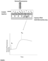
- Figure 1 above illustrates the principle.
- the term "metal sub-nanostructure” refers to a metallic structure formed on the surface of the concave microcavity having a metl is gold dimension that is configured to enhance a localised in-cavity plasmonic field typically by focussing the electric field towards a bottom of the microcavity. Plasmonically structuring the arrays through the incorporation of sub-nanostructures yields dramatically improved S/N of signal to interrogate the molecule by SERS or through use of surface enhanced resonance Raman spectroscopy (SERRS), where the excitation laser wavelength is matched to an electronic transition outstanding enhancement of Raman signature from non-luminescent species to can be investigated.
- the sub-nanostructure has a dimension of 5-200 nm.
- An example of a concave microcavity having a sub-nanostructure is shown in Figure 5 .
- Various methods for forming sub-nanostructures in concave microcavities are disclosed herein.
- direct photo-induced metal deposition may be employed to produce imprints of the plasmonic fields near the bottom of the cavity, thereby allowing for plasmonically-tagged drug arrival-time studies.
- 3D-nanoprinting via 2-photon polymerization of photoresist e.g. acrylate photoresist
- photoresist e.g. acrylate photoresist
- These nano-structures may be computationally designed via, for instance, inverse algorithm.
- Plasmonic field induced polymerization/metal deposition may be employed, where the plasmonic hots spot from the cavity array itself is used to deposit additional nanostructuring through direct metal photodeposition where cavities are filled with a metal salt solution or where a polymer solution filled in the cavity and photoinduced cross-linking driven by the plasmonic field is used to create insoluble polymer structures that can be deposited over with metal vapour deposition following washing to create hot spots.
- Air bubble excluded zone nanoparticle prep ( Figure 2 ): Following filling by Fluorescence and SEM imaging of templated PDMS confirm that without sonication a small liquid unfilled region of the cavity is formed. We exploit this by, without sonication, filling Au cavity array pre-coated with C6 with an aqueous/ethanolic solution of surface active thiol. This blocks all but the region of the cavity where the air bubble is. Gold is then electrodeposited principally at the unmodified regions of the array to yield gold particles at the position of the air bubble in the well.
- the invention describes a highly versatile assay to determine the molecular interactions of molecules (e.g. drugs, agrichemicals or toxins) with biomimetic models of the cell membrane comprised of phospholipid bilayers supported across metal nanocavity arrays as model membranes.
- molecules e.g. drugs, agrichemicals or toxins
- the substrates provide electric field enhancement at discrete regions due to the Purcell effect, reflectance and/or localised surface plasmon located so that it is either coincident with the lipid bilayer and or below bilayer.
- Two types of platforms are described, conventional (plasmonic) metallic cavity arrays supporting lipid or lipid/protein bilayers and plasmonically enhanced arrays supporting lipid bilayers or lipid or lipid/protein where plasmonic hot spots within the arrays are augmented by implementation of additional nanostructures within the substrates to give spatially localised and augmented plasmonic enhancement of signal.
- the platforms may be used with normal incident angle excitation and collection of light or with angled incident and collection to achieve control over the region of study (bilayer or well).
- Enhancement is provided in the case of fluorescence from by metal enhanced fluorescence which may arise from plasmonic promotion of excitation cross section, the radiative rate constant or through the focussing of the field within the cavity.
- SERS enhancement is achieved through excitation of the localised plasmon resonance of the cavity/surface.
- the location of the most intense electric field (plasmonic) may be controlled 1) by manipulation of excitation angle 2) by varying the material, nanostructuring (3) the excitation wavelength or 4) by controlling the focused field-structure via phase modulation.
- FIG.1 illustration of membrane transport detection. Illustration of the operation of the bilayer permeation assay PlasMem: The dynamics of molecular (e.g. drug) passive diffusion across the membrane suspended at a gold nanocavity array is followed through the evolving (surface enhanced) Raman or Fluorescence signal from the analyte which is enhanced as it reaches the plasmonic hot spot at the cavity interior after crossing the membrane. This provides a simple but quantitative indication of reagent permeation through the bilayer. Drug permeation/arrival time, drug membrane residence time and detailed membrane-drug structural information can be gleaned from this method.
- the light collection/detection system can be a microscope or lense/collection optics can be built into a microfluidic chip or built into the instrumental reader (Raman/fluorescence).
- the bilayer itself can be monitored by metal (plasmonically and/or reflectance/Purcell effect) enhanced fluorescence or by surface enhanced Raman spectroscopy to study vibrational spectroscopy of drug- membrane binding or the cavity interior can be monitored to cavity to identify permeation of the molecule (marked by arrival SERS or fluorescence signal) and to elucidate dynamics of diffusion across the membrane as a function of membrane composition, (lipid composition, presence of proteins or transporters) molecular (or particle concentration) or environmental conditions (pH, ionic strength)
- Figure 1 illustrates the principle; The dynamics of transmembrane transport can be evaluated as a function of bilayer composition alongside structural interrogation of drug-membrane interaction/partitioning.
- molecule drug, particle polymer
- determination of the arrival time from of e.g. a drug administered to the proximal interface of the bilayer will be determined from the fluorescence or Raman enhancement emission intensity increase (or appearance) that arises as the species reaches the hot spot at the cavity interior after crossing the membrane. This provides a simple but quantitative indication of reagent permeation through the bilayer.
- Drug permeation/arrival time can be interrogated against various other conditions including drug concentration, pH, ionic gradient and the chemical composition of the membrane.
- the lipid bilayer membrane can be a simple single phospholipid species such as DOPC or more complex ternary or beyond with compositions that mimic true bilayers including inclusion of protein, and can be selected to mimic disease or specific physiological organelles or tissues or indeed species such as bacteria.
- the substrates can be unmodified metal (gold, silver or combinations of metals) comprising only the cavity array that can be prepared by microsphere lithography, or through 3D printing mask or direct printing and metal deposition protocols.
- Incorporation of additional plasmonic hot spots can be included in a hierarchical configuration, in which the strength and position of the plasmonic hot-spots can be prudently customized to suit the experiment requirements. For instance, one can employ direct photo-induced metal deposition to produce imprints of the plasmonic fields near the bottom of the cavity, thereby allowing for plasmonically-tagged drug arrival-time studies. Alternatively, one can also employ 3D-nanoprinting via 2-photon polymerization of photoresist (e.g. acrylate photoresist) to produce customized sub-nanostructure within the cavity. These nano-structures may be computationally designed via, for instance, using numerical methods to anticipate optical properties such as Finite Difference
- FDTD Domain Domain
- the invention provides a unique approach to assessment of molecular membrane permeability which exploits the cavity nature ( Figure 6 ) of the arrays and their plasmonic fields (metallic structures).
- the assay utilizes the peak plasmonic fields within the nano/micro cavity to report the arrival of a drug after it transports across the cell membrane model based on Raman or emission signal from the molecule.
- the assay itself is unique as drug-membrane molecular interactions and partitioning across porous arrays has not been reported by SERS previously and the dynamic monitoring drug transport across membrane suspended over a nanostructure using metal enhanced fluorescence/SERS/SERRS enhancement for arrival time measurement is not previously reported.
- FIG. 9 shows the FDTD-simulation results of cavities containing sub-nanostructures, illustrating the possibility of creating localized in-cavity plasmonic fields.
- the specific geometry of the cavity platform described here also permits modulation of the excitation fields to excite different plasmonic modes.
- the present invention allows the kinetics of drug binding and permeation on conventional array substrates to be observed and monitored down to nanomolar concentrations with high signal-to-noise analysis of drug-membrane interactions.
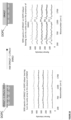
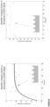
- it is possible to access signal across a range of physiologically relevant concentrations ( Figures 9 , 10 and 11 ).
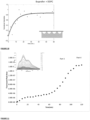
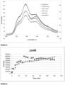
- its interaction with the bilayer may lead to modifications to the emissions spectrum. This was observed in the case of doxorubicin and duanorubicin both of whom show transitory shifts in emission peak maximum and relative intensity of the vibrational progression whilst in the bilayer.
- the solution spectrum is recovered when the drug reaches the well where greatest enhancement occurs and this dominates the spectral contributions, see for example Figure 12 .
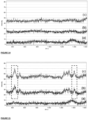
- this assay can also distinguish between drugs that are permeable and non-permeable, for example in Figure 13 a ternary lipid bilayer comprising DOPC:SM:Chol of 40:40:20 %mol/mol was employed and as the figure shows the emission from two replicate measurements of 0.1 mM of the drug reaches as stead state after less than 20 mins, which corresponds to the time taken for the drug in the unstirred solution to distribute homogenously.
- the final intensity achieved for this drug when it reaches the cavity is roughly 2 orders of magnitude higher than the intensity observed here.
- Arrays were prepared using Gold wafer discs (AMS Biotechnology limited) consisting of a non-conductive silicon base, a 10nm titanium layer for adhesion and a 100nm gold layer, cut into approx 1.5 ⁇ 0.8 cm. The substrates were washed carefully with acetone, ethanol and water before drying under nitrogen. Substrates were then used directly or placed into the vacuum chamber of a Harrick PDC-002 plasma cleaner (Harrick Plasma) and were air-plasma treated during 5 minutes at a pressure of 1000 mTorr using high power setting (29.6 W applied to the RF coil).
- Gold wafer discs AMS Biotechnology limited
- the substrates were washed carefully with acetone, ethanol and water before drying under nitrogen. Substrates were then used directly or placed into the vacuum chamber of a Harrick PDC-002 plasma cleaner (Harrick Plasma) and were air-plasma treated during 5 minutes at a pressure of 1000 mTorr using high power setting (29.6 W applied to the RF coil).
- the chips are mounted onto a holder and 20 ⁇ l of polystyrene spheres (Polysciences Inc.)
- PS spheres solutions of 3 ⁇ m, 1 ⁇ m, 850 ,700 and 510 nm diameter were purchased from Polysciences, Inc. and were respectively diluted to between 1 and 1.4% (% solid wt. in solution) in deionised water.
- 20 ⁇ L of the diluted solution was then drop casted onto the clean gold-silicon substrates before covering it with a clean microscope glass slide (Corning ® Inc) at a contact angle of 2°.) at 1% (w/v) solution was deposited onto the gold wafers.
- a glass slide was then placed over the chip causing a capillary effect.
- the mounted chips were placed onto a platform at an angle that encourages monolayer formation of the sphere.
- the chips were left to dry overnight at 4 0C, the liquid evaporated fully, resulting in a thin layer of spheres across the chip. This was then examined under a light microscope to determine if multilayers occurred. A small area at the edge of the chip is then removed of spheres using tape.
- Gold deposition was completed by immersing the sample in a gold salt solution (Technic inc) that was previously degassed with nitrogen for 15 minutes. Deposition was performed using a standard 3 electrode set up. The sample acts as the working electrode, while an Ag/AgCI is used as the reference electrode and a platinum wire as a counter electrode.
- a gold salt solution Technic inc
- Deposition conditions vary depending on the deposition solution, but typically a potential of -0.6 V was applied by an electrochemical workstation 990 CH instrument. When the optimal charge is reached the samples are then removed, rinsed with deionised water and left to dry.
- the array was left in contact with an ethanol or (80:20 ethanol water solution of 1 mM) of the deposition OH terminated thiol (typically 6-mercaptohexanol) overnight.
- the spheres are then removed by immersing the cavity in Tetrahydrofuran (THF) and sonicating for 5 up to 30 minutes (the PS was confirmed gone by EIS and/or Raman spectroscopy) and the resulting substrates where then characterised by SEM.
- THF Tetrahydrofuran
- Gold electrodeposition was then performed through the PS microspheres template using a potentiostat CH Instrument model 900 electrochemical workstation and an Elevate ® gold 7990 salt solution from Technic Inc. USA. The solution was degassed by purging for 30 minutes with nitrogen. In the electrodeposition, the gold-silicon wafer was the working electrode, with a Ag/AgCI reference electrode and a platinum wire as counter electrode. Gold was then electrodeposited at an applied potential of -0.6 V until the equator of the PS spheres monolayer was reached, trapping them within the substrate. This characteristic point was easily controlled by monitoring the shape of the i-t curve.
- the tape on the substrate was then peeled off and the sample was rinsed with deionised water to wash away any gold salt solution remaining.
- the PMMA based platform holding the tilted stages was then put in a box with silica-gel to reduce the ambient moisture and substrates were left to dry overnight at a temperature of 4°C. Once the water fully evaporated, the gold-silicon substrates show an iridescent deposit indicative of a closed packed monolayer of dry PS spheres.
- a tape with a circular hole of not more than 5 mm diameter was placed on the substrate, while ensuring that the hole was centred on a homogeneous iridescent area. A top band of the tape was then removed to allow connection with the potentiostat.
- Micro and nano PS beads half embedded in gold were physically modified using a dry etching method (adapted from Plettl et al. and Yang et al.). Substrates were place in the vacuum chamber of a Plasmalab 80 Plus Reactive Ion Etch System (Oxford Instruments) and were reacted in the oxygen plasma at a constant oxygen flow of 25 sccm and a chamber pressure of 50 mTorr. RF power applied varied from 50 W to 200 Wand exposure time from 2 minutes up to 40 minutes depending on the size of the spheres to be etched and the size of the nanoparticles to be obtained.
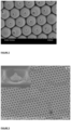
- substrates were sputter coated with gold using a sputter coater Model 108 from Agar scientific. After coating for 30 seconds at a current of 30 mA and a pressure of 0.08 mbar, substrates were then ready for characterisation ( Figure 1 ), chemical surface modification, SERS or Metal Enhanced Fluorescence (MEF) applications.
- Figure 1 Characterisation
- SERS Metal Enhanced Fluorescence
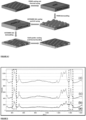
- Nanostructured pores prepared using the exclusion volume of aqueous filled pores were prepared using the exclusion volume of aqueous filled pores.
- Step 1 and 2 show the usual sphere gold deposition and modification of the top surface with thiol.
- Step 3 after the spheres are removed an ethanol/water solution containing thiol is then added to dried cavities without sonication and left for 8 hours.
- Step 4 - the thiol has deposited everywhere except the excluded volume and in Step 5 after sonicating the gold deposition solution into the array a second electrodeposition is performed to assemble particles at the unmodified regions of the array.
- the arrays were prepared as above, and after removal of the PS spheres and washing the arrays were dried under vacuum.
- the arrays were then left in contact (without sonication or agitation) with a deposition solution of solution was soinicated in gently for 5 mins.
- the electrodeposition step was then repeated under conditions described above for varying times (typically approximately 30 to 50 seconds) and the resulting arrays were imaged by SEM as shown below. In general NPs were larger if gold deposition solution is sonicated into the array.
- Figure 20 shows nanoparticle modified arrays prepared from 3 um PS sphere assemblies after 30 seconds gold electrodeposition. (gold deposition left in contact with array left and middle) and after prior sonication fo gold deposition solution
- Microarray fabrication process starts with the design and fabrication of negative master mould.
- the mould can be a simple hemispherical array or can incorporate nanostrucutres - including single nanostructures or pillars with varying gap at the bottom of the well:
- the design is performed applying SolidWorks software.
- the negative round cavities of different diameters, ranging from 1 till 3 ⁇ m, and different depths from 0.5 till 3 ⁇ m are designed.
- all the designs including all the dimensions are scaled up by 1.5, 2, 2.5 and 3 times.
- Nanoscribe 2-photon 3D printer is applied for this purpose, as it enables to fabricate the features of designed dimensions. Moreover, unlike most of lithographic techniques it allows to fabricate round shaped features.
- the master mould is printed from IP-Dip photoresist.
- the 3D printed part is sputter coated with 30 nm of gold.
- the positive master mould is fabricated from Polydimethylsiloxane (PDMS).
- PDMS Polydimethylsiloxane
- the SYLGARD ® 184 PDMS pre-polymer from Sigma Aldrich is prepared as follows: the base and curing agent are mixed in a ratio of 10:1 by mass respectively.
- 3D printed mould is nitrogen blown, in order to remove the dust and dirt from it.
- Mixed pre-polymer is casted onto negative 3D printed master mould and placed into desiccator for entrapped air removal. Subsequently, pre-polymer is placed in the oven (temperature 50 °C) for 12 hours, in order to be cured.
- the hardened positive PDMS part is demoulded.
- the dual-cure off-stoichiometry thiol-ene polymer (OSTE+) OSTEMER 322 Crystal Clear by Mercene Labs is applied in the fabrication of negative microarray.
- Two OSTE+ constituents A and B are mixed by ratio 1.09 to 1.
- the PDMS mould is nitrogen blown for dust and dirt removal.
- the mixed pre-polymer is then casted onto the positive master mould from PDMS.
- the desiccation of pre-polymer is performed.
- the vacuum chamber is covered with aluminium foil, in order to protect the pre-polymer from light and therefore premature hardening during the desiccation.
- the desiccated part is then placed under the UV lamp (wavelength 365 nm) for 15 minutes.
- the demoulded polymer part is rubbery and contains the unreacted thiols and epoxies.
- the gold coating of 140 ⁇ m is then sputtered on top of the fabricated negative part.
- the final step is the second thermal curing (1 hour at 90 °C), during which all thiols and epoxies react, the polymer becomes stiff and the fabricated microarray ( figure 2 ) due to epoxy interaction binds to the sputter coated gold.
- the millimetre range arrays of negative SSVs are designed applying Computer Aided Design (CAD). Subsequently, the design is converted into STL format. DeScribe software is applied for scaling down the design to micrometre range (diameter 2 to 3 ⁇ m and depth 1 to 6 ⁇ m) and converting into compatible for 2 photon Photonic Professional GT 3D printer from NanoScribe GmbH. Consequently, negative master mould is printed on the Indium Tin Oxide (ITO) coated glass substrate (area 25 ⁇ 25 mm; height 0.7 mm) according to the design. IP-Dip photoresist is applied in the printing process.
- ITO Indium Tin Oxide
- Sylgard 184 from Sigma-Aldrich PDMS precursor in 10:1 base to curing agent ratio is mixed, degassed and casted onto 3D printed negative master mould, which is placed in the bath, following with additional desiccation (No visible entrapped air bubbles should be present).
- the part is thermally hardened at the temperature of 100 °C for 5 hours, gradually cooled down till room temperature and demoulded.
- OSTE+ precursor is mixed by 1.09:1 A to B components ratio, degassed and casted over the positive PDMS mould. After casting additional degassing is performed, because during the casting air is entrapped, this could lead to inferior quality of the substrate.
- UV light wavelength 365 nm
- UV-initiated radical polymerization results in a cross-linking network of the part of thiol and of all -ene groups in the allyls, therefore part of thiol functional groups and free monomers with epoxide functional groups remain unreacted.
- the UV cured part becomes rubbery, i.e. can be deformed and is surface modifiable.
- the part is demolded- negative SSVs are obtained. Subsequently 0.1 ⁇ m of gold is sputter coated on SSV substrate applying Agar Sputter Coater.
- the part is thermally cured at the temperature of 110 °C (1 hour for every millimetre of the substrate thickness), in order to induce the reaction between unreacted excess of thiol groups and epoxies.
- the polymer hardens and due to epoxy chemistry creates a bond with a wide number of materials including gold. Polymer demonstrates complete inertness and decent barrier characteristics after thermal curing.
- Figure 5 shows the Raman enhancement achieved when the arrays are fabricated using this method:
- the assemblies were first modified with a OH terminated thiol (typically) 6-mercaptohexanol at the top surface by immersing the array in a ethanolic solution (1 mM) of the thiol for approx. 10 hours.
- a OH terminated thiol typically 6-mercaptohexanol
- lipid mixture (across single or diverse lipid compositions) was prepared in chloroform at a concentration of 1 mg/ml. 50 ⁇ L of this solution was suspended on the water sub-phase. Fifteen minutes were allocated for evaporation of the solvent, prior to lipid monolayer compression.
- the rate of compression was 30 cm2/min and a constant surface pressure of 32 mN/m was maintained during the transfer of a probe labelled lipid monolayer from the water-air interface to the aqueous filled microcavity array. During LB transfer, the rate of the dipper motion was 5 mm min-1 to ensure adequate transfer.
- the monolayer coated template was either incorporated into the flow chamber by sticking the edges of the gold to a microfluidic substrate or simply through which lipid vesicles (100 nm SUVs (see below) of the same or different composition were containing lipid probe were injected into the flow chamber where the spontaneously disrupt to form a free-spanning lipid bilayer.
- the flow chamber was flushed with 1ml of 0.01 M PBS buffer to remove excess vesicles and to maintain the fluid above the bilayer.
- PBS phosphate buffer saline
- the dried lipid films were rehydrated in 1 ml of 0.01 M phosphate buffer saline (PBS), pH 7.4 or 0.02mM Tris buffer, pH 5.25 and vortexed for a period of 30-60 seconds.
- the lipid suspensions were extruded 11 times through a 100 nm polycarbonate filter using a mini-extruder (Avanti Polar Lipids) to form large unilamellar vesicles (LUV) and diluted to final concentration of 0.25 mg/ml.
- a mini-extruder Advanti Polar Lipids
- LUV large unilamellar vesicles
- Lipid bilayer assembly was confirmed by fluorescence imaging, obtaining the Raman (SERS spectrum of the bilayer and in particular by running EIS of the assembled film prior to running Raman/fluorescence assays.
- EIS Electrochemical Impedance Spectroscopy
- EIS was performed on a CH660A potentiostat (CH Instruments, Germany).
- a standard 3-electrode cell was employed which comprised of an Ag/AgCI reference electrode, a platinum auxiliary electrode and the gold microcavity array which constituted the working electrode.
- the EIS was measured over a frequency range of 1 MHz to 0.01 Hz with an AC modulation amplitude of 5 mV at a potential bias of 0 V (vs Ag/AgCI). All measurements were carried out in a glass cell (approximate volume of 20 ml) in contact with PBS buffer maintained at pH 7.4 or 20 mM Tris buffer at pH 5.25.
- the EIS of the aqueous filled microcavity array coated with the DOPC lipid bilayer was measured initially prior to addition of drugs to ensure signal stability and then titrate drug solutions into the glass cell containing buffer and the electrochemical impedance response of the lipid bilayer following drug introduction was measured for each concentration. Each measurement takes approximately 10 minutes and the measurements were carried out at room temperature (20 °C). The measured data were analysed using Z-View software using the fitting model (Scheme 1) to calculate the change in membrane resistivity and conductance.
- the EIS data were fitted to the equivalent circuit model (ECM) shown in Figure 16 which was described previously for the lipid bilayer modified microcavity array electrode.
- the circuit consists of the solution resistance (Rsol) in series with a resistor and a capacitor, which are in parallel and correspond to the electric and dielectric properties respectively of membrane deposited on the electrode surface (Rm, Cm).
- the ECM also contains an additional component to account for the resistance of the cavity arrays (Rarray), and the double layer capacitance (Cdl).
- the data for the bare cavities and cavities upon treatment with ME were fitted with a Rsol(Rm
- a Constant Phase Elements (CPE) is used in the equivalent circuit instead of pure capacitors to account for surface defects on both the electrode surface and the lipid bilayer.
- Rsol values may change depending on the nature of the drug, e.g. where it carries a charge but everything else remains static. Both Ibu and Dic are negatively charged under the pH conditions used here. Rarray is not expected to vary within a sample as there are no changes occurring in this component of the electrical system. Cm and Rm are connected in parallel.
- the membrane acts as an impermeable and insulating medium in biological cells as both the intracellular and extracellular environments contain various concentrations of ionic salt solutions permitted by the membrane.
- there is an external and internal environment comprising PBS buffer separated by a semi-permeable phospholipid bilayer. Essentially, this insulating bilayer is separating two ionic phases and is hence acting as a capacitor.
- a Horiba Labram HR instrument was used for both Raman and fluorescence measurements using a 50x long distance magnification objective (Leica).
- the wavelengths were typically 473nm and 785nm were used for fluorescence measurements and Raman measurements respectively.
- the instrument was calibrated using silicon prior to use. Samples were placed either on a clean glass slide or if required to be immersed in liquid in a small clean glass petri dish or were in microfluidic format. The laser was focused using the camera and spectra were taken. Typically a 1% neutral density filter and 300 ⁇ m slit were used for fluorescence and no filter for Raman. The spectrometers grating was kept consistent at 600 XX.
- drug solutions were prepared as stock solutions for introduction into the bilayer contacting solution dissolved in PBS or Tris buffer at concentrations that permitted final concentrations (on contact with the bilayer buffer) of 1 nM to several millimolar.
- drugs were particularly insoluble ethanol, methanol or DMSO could be used to pre-dissolve the drug to get it into buffer. In all cases final organic concentration was less than 0.5% (and controls using EIS confirmed this did not affect permeability).
- Drug diffusion samples were analysed by first obtaining a bilayer spectra while sample is immersed in PBS.
- a total of volume about 2ml was flowed through the microfluidics in order to equalise concentration gradient in the channel. This is accomplished within 1-min, after which time-series measurements commenced, and continued at 3-5min interval for a period of 45 - 50min. All collected spectra were background-corrected, and a dynamic curve was then plotted selecting a characteristic SERS peak for the sample which may also be normalised to a background peak such as that of silicon or buffer.
- stages milled from Teflon with angle normal to the microsope stage ranging from 10 to 60° was used.
Landscapes
- Health & Medical Sciences (AREA)
- Chemical & Material Sciences (AREA)
- Life Sciences & Earth Sciences (AREA)
- General Health & Medical Sciences (AREA)
- Analytical Chemistry (AREA)
- Engineering & Computer Science (AREA)
- Physics & Mathematics (AREA)
- Immunology (AREA)
- Hematology (AREA)
- General Physics & Mathematics (AREA)
- Biochemistry (AREA)
- Pathology (AREA)
- Biomedical Technology (AREA)
- Chemical Kinetics & Catalysis (AREA)
- Dispersion Chemistry (AREA)
- Clinical Laboratory Science (AREA)
- Nuclear Medicine, Radiotherapy & Molecular Imaging (AREA)
- Molecular Biology (AREA)
- Urology & Nephrology (AREA)
- Medicinal Chemistry (AREA)
- Food Science & Technology (AREA)
- Nanotechnology (AREA)
- Spectroscopy & Molecular Physics (AREA)
- Biophysics (AREA)
- Microbiology (AREA)
- Cell Biology (AREA)
- Biotechnology (AREA)
- Investigating, Analyzing Materials By Fluorescence Or Luminescence (AREA)
Claims (15)
- Méthode de dosage de la perméation d'une molécule à tester à travers une bicouche lipidique qui utilise un dispositif microfluidique comprenant :un substrat ayant au moins une microcavité concave définissant une ouverture et ayant une surface métallique, et un liquide disposé au sein de la microcavité ;une bicouche lipidique en suspension à travers l'ouverture ; etun canal microfluidique contenant un liquide disposé au-dessus du substrat en communication fluide avec la bicouche lipidique ;où le liquide dans la microcavité est séparé du liquide dans le canal microfluidique par la bicouche lipidique en suspension,la méthode comprenant les étapes :de passage d'un liquide contenant une molécule à tester à travers le canal microfluidique ; etde suivi de l'intensité d'un signal Raman ou fluorescent provenant de la molécule à tester lorsqu'elle s'infiltre à travers la bicouche et dans le liquide dans la microcavité et arrive au niveau d'un champ plasmonique amélioré par les métaux au sein de la microcavité par spectroscopie fluorescente ou Raman améliorée de manière plasmonique.
- Méthode selon la revendication 1, dans laquelle l'étape de suivi comprend une spectroscopie Raman améliorée de manière plasmonique.
- Méthode selon la revendication 2, dans laquelle l'étape de suivi comprend une spectroscopie Raman exaltée de surface (SERS) qui utilise une lumière d'excitation qui coïncide avec le plasmon du métal.
- Méthode selon la revendication 2, dans laquelle l'étape de suivi comprend une spectroscopie Raman de résonance exaltée de surface (SERRS) qui utilise une lumière d'excitation qui est en résonance avec l'absorption de la molécule à tester.
- Méthode selon l'une quelconque des revendications précédentes, dans laquelle l'étape de suivi comprend le suivi du temps de rétention de la molécule à tester dans la le suivi du temps de séjour de la molécule dans la bicouche lipidique.
- Méthode selon la revendication 1 ou 5, dans laquelle la spectroscopie est une spectroscopie de fluorescence améliorée par les métaux.
- Méthode selon la revendication 6, dans laquelle la molécule est fluorescente ou comprend un marqueur fluorescent.
- Méthode selon l'une quelconque des revendications précédentes, dans laquelle la surface métallique de la microcavité comprend une sous-nanostructure métallique ayant une dimension submicronique configurée afin d'améliorer un champ plasmonique localisé intra-cavité.
- Méthode selon la revendication 8, dans laquelle la sous-nanostructure métallique présente une dimension de 5-200 nm.
- Méthode selon la revendication 8, dans laquelle l'étape de suivi comprend une SERS ou une SERRS et où on fait correspondre la longueur d'onde du laser d'excitation avec une amélioration de la transition électronique de la signature Raman issue des espèces non luminescentes à étudier.
- Méthode selon la revendication 8 ou 9, dans laquelle la sous-nanostructure métallique est fabriquée par une méthode choisie dans le groupe constitué par : le dépôt de métal photo-induit direct pour produire des empreintes des champs plasmoniques ; la nano-impression 3D via la polymérisation à deux photons de résine photosensible ; la polymérisation induite par champ plasmonique/dépôt de métal ; la préparation de nanoparticules à zone exclue par bulle d'air ; et la gravure ionique réactive (RIE).
- Méthode selon la revendication 11, dans laquelle les empreintes des champs plasmoniques sont proches du fond de la cavité.
- Méthode selon l'une quelconque des revendications précédentes, dans laquelle la molécule à tester est un médicament.
- Méthode selon l'une quelconque des revendications précédentes, dans laquelle la surface métallique de la au moins une microcavité est choisie parmi l'or, l'argent, ou un Ostemer.
- Méthode selon la revendication 14, dans laquelle le métal est l'or, et où une longueur d'onde de la ligne d'excitation est configurée pour coïncider avec l'absorption plasmonique de l'or, ou une excitation ou une émission doit coïncider avec l'énergie du champ plasmonique pour une amélioration.
Applications Claiming Priority (2)
| Application Number | Priority Date | Filing Date | Title |
|---|---|---|---|
| GB1809527.3A GB2574600A (en) | 2018-06-11 | 2018-06-11 | A method and device for assaying the interaction and dynamics of permeation of a molecule and a lipid bilayer |
| PCT/EP2019/065044 WO2019238589A1 (fr) | 2018-06-11 | 2019-06-07 | Procédé et dispositif de dosage de l'interaction et de la dynamique de perméation d'une molécule et d'une bicouche lipidique |
Publications (3)
| Publication Number | Publication Date |
|---|---|
| EP3811078A1 EP3811078A1 (fr) | 2021-04-28 |
| EP3811078C0 EP3811078C0 (fr) | 2025-01-22 |
| EP3811078B1 true EP3811078B1 (fr) | 2025-01-22 |
Family
ID=62975390
Family Applications (1)
| Application Number | Title | Priority Date | Filing Date |
|---|---|---|---|
| EP19733408.9A Active EP3811078B1 (fr) | 2018-06-11 | 2019-06-07 | Procédé et dispositif de dosage de l'interaction et de la dynamique de perméation d'une molécule et d'une bicouche lipidique |
Country Status (4)
| Country | Link |
|---|---|
| US (1) | US11892406B2 (fr) |
| EP (1) | EP3811078B1 (fr) |
| GB (1) | GB2574600A (fr) |
| WO (1) | WO2019238589A1 (fr) |
Families Citing this family (6)
| Publication number | Priority date | Publication date | Assignee | Title |
|---|---|---|---|---|
| CN110184045B (zh) * | 2019-05-17 | 2022-04-15 | 太原理工大学 | 一种提高荧光纳米粒子远场定向发光的复合结构 |
| CN114486845B (zh) * | 2021-12-31 | 2023-08-04 | 杭州电子科技大学 | 一种制备纳米球形蜂窝结构的方法 |
| CN115290712B (zh) * | 2022-07-07 | 2025-05-02 | 中国检验认证集团辽宁有限公司 | 基于激光诱导石墨烯电极的纸基立体微流控生物传感器 |
| CN115096871B (zh) * | 2022-07-22 | 2022-12-23 | 香港科技大学深圳研究院 | 应用于多通道的sers微流控芯片的检测装置 |
| CN115586170B (zh) * | 2022-09-26 | 2024-12-06 | 广西电网有限责任公司电力科学研究院 | 一种矿物绝缘油中二苄基二硫醚含量的sers测定方法 |
| CN119846044B (zh) * | 2025-03-21 | 2025-05-30 | 浙江大学 | 一种基于临界角反射的电化学成像系统和实时监测方法 |
Family Cites Families (3)
| Publication number | Priority date | Publication date | Assignee | Title |
|---|---|---|---|---|
| KR101211532B1 (ko) * | 2011-08-24 | 2012-12-12 | 인하대학교 산학협력단 | 대면적의 불규칙적인 배열을 갖는 플라즈모닉 나노 우물 구조 및 그 제조방법 |
| GB2527827A (en) * | 2014-07-03 | 2016-01-06 | Univ Dublin City | Microfluidic nanopore array supporting a lipid bilayer assembly |
| KR101527849B1 (ko) * | 2014-11-19 | 2015-06-10 | 선문대학교 산학협력단 | 플라즈모닉 금속 박막에 형성된 금속 멤브레인 상의 드릴 형 나노포어 및 그 형성방법 |
-
2018
- 2018-06-11 GB GB1809527.3A patent/GB2574600A/en not_active Withdrawn
-
2019
- 2019-06-07 EP EP19733408.9A patent/EP3811078B1/fr active Active
- 2019-06-07 WO PCT/EP2019/065044 patent/WO2019238589A1/fr not_active Ceased
- 2019-06-07 US US16/973,557 patent/US11892406B2/en active Active
Also Published As
| Publication number | Publication date |
|---|---|
| WO2019238589A1 (fr) | 2019-12-19 |
| GB201809527D0 (en) | 2018-07-25 |
| US20210247314A1 (en) | 2021-08-12 |
| GB2574600A (en) | 2019-12-18 |
| EP3811078A1 (fr) | 2021-04-28 |
| EP3811078C0 (fr) | 2025-01-22 |
| US11892406B2 (en) | 2024-02-06 |
Similar Documents
| Publication | Publication Date | Title |
|---|---|---|
| EP3811078B1 (fr) | Procédé et dispositif de dosage de l'interaction et de la dynamique de perméation d'une molécule et d'une bicouche lipidique | |
| US12540937B2 (en) | Apparatus for supporting an array of layers of amphiphilic molecules and method of forming an array of layers of amphiphilic molecules | |
| AU2008337348B2 (en) | Formation of layers of amphiphilic molecules | |
| US9012172B2 (en) | Devices comprising muscle thin films and uses thereof in high throughput assays for determining contractile function | |
| Lin et al. | Supported membrane formation, characterization, functionalization, and patterning for application in biological science and technology | |
| CA3052140A1 (fr) | Dispositifs de sequencage a semi-conducteurs comprenant des materiaux de couche bidimensionnelle | |
| WO2018152296A1 (fr) | Sensibilité et spécificité améliorées pour micro-biopuce de point de soins (poc) | |
| US20180237602A1 (en) | A transparent or semi-transparent nanostructured latex film for flexible and semi-transparent electronics for monitoring and manipulating cellular processes | |
| JP6462746B2 (ja) | 帯電したナノ粒子の連続勾配を有する表面、接着現象の分析用の装置、ならびに表面および装置の使用 | |
| Ogier et al. | Suspended planar phospholipid bilayers on micromachined supports | |
| Huang et al. | Superhydrophobic–superhydrophilic hybrid surface with highly ordered tip-capped nanopore arrays for surface-enhanced Raman scattering spectroscopy | |
| Lazzara et al. | Separating attoliter-sized compartments using fluid pore-spanning lipid bilayers | |
| JP7442781B2 (ja) | プラズモニックセンサ用の部材およびその製造方法 | |
| de Leon et al. | Formation of multigradient porous surfaces for selective bacterial entrapment | |
| Frese et al. | In situ generation of electrochemical gradients across pore-spanning membranes | |
| US20040228774A1 (en) | Microreactor, its production method, and sample screening device | |
| Lazzara et al. | Orthogonal functionalization of nanoporous substrates: Control of 3D surface functionality | |
| JP5345078B2 (ja) | 脂質二重膜、それを形成するために用いられる自己支持性フィルム及びそれを具備するマイクロ流路デバイス | |
| JP2013044604A (ja) | 金属酸化物の絶縁膜を用いたバイオチップ | |
| Han et al. | 3D artificial cell membranes as versatile platforms for biological applications | |
| US20250153164A1 (en) | Hydrogel channel device with sensor | |
| WO2022136262A1 (fr) | Détection de traces en temps réel | |
| Lettieri et al. | DPPTE Thiolipid Self-Assembled Monolayer: A Critical Assay | |
| KR20150117110A (ko) | 랩온어칩 및 이의 제조 방법 | |
| Maguire | Biomimetic models–the support of cell membranes on micro cavity arrays |
Legal Events
| Date | Code | Title | Description |
|---|---|---|---|
| STAA | Information on the status of an ep patent application or granted ep patent |
Free format text: STATUS: UNKNOWN |
|
| STAA | Information on the status of an ep patent application or granted ep patent |
Free format text: STATUS: THE INTERNATIONAL PUBLICATION HAS BEEN MADE |
|
| PUAI | Public reference made under article 153(3) epc to a published international application that has entered the european phase |
Free format text: ORIGINAL CODE: 0009012 |
|
| STAA | Information on the status of an ep patent application or granted ep patent |
Free format text: STATUS: REQUEST FOR EXAMINATION WAS MADE |
|
| 17P | Request for examination filed |
Effective date: 20210111 |
|
| AK | Designated contracting states |
Kind code of ref document: A1 Designated state(s): AL AT BE BG CH CY CZ DE DK EE ES FI FR GB GR HR HU IE IS IT LI LT LU LV MC MK MT NL NO PL PT RO RS SE SI SK SM TR |
|
| AX | Request for extension of the european patent |
Extension state: BA ME |
|
| DAV | Request for validation of the european patent (deleted) | ||
| DAX | Request for extension of the european patent (deleted) | ||
| STAA | Information on the status of an ep patent application or granted ep patent |
Free format text: STATUS: EXAMINATION IS IN PROGRESS |
|
| 17Q | First examination report despatched |
Effective date: 20220929 |
|
| P01 | Opt-out of the competence of the unified patent court (upc) registered |
Effective date: 20230523 |
|
| GRAP | Despatch of communication of intention to grant a patent |
Free format text: ORIGINAL CODE: EPIDOSNIGR1 |
|
| STAA | Information on the status of an ep patent application or granted ep patent |
Free format text: STATUS: GRANT OF PATENT IS INTENDED |
|
| INTG | Intention to grant announced |
Effective date: 20240321 |
|
| GRAJ | Information related to disapproval of communication of intention to grant by the applicant or resumption of examination proceedings by the epo deleted |
Free format text: ORIGINAL CODE: EPIDOSDIGR1 |
|
| STAA | Information on the status of an ep patent application or granted ep patent |
Free format text: STATUS: EXAMINATION IS IN PROGRESS |
|
| INTC | Intention to grant announced (deleted) | ||
| GRAP | Despatch of communication of intention to grant a patent |
Free format text: ORIGINAL CODE: EPIDOSNIGR1 |
|
| STAA | Information on the status of an ep patent application or granted ep patent |
Free format text: STATUS: GRANT OF PATENT IS INTENDED |
|
| INTG | Intention to grant announced |
Effective date: 20241106 |
|
| GRAS | Grant fee paid |
Free format text: ORIGINAL CODE: EPIDOSNIGR3 |
|
| GRAA | (expected) grant |
Free format text: ORIGINAL CODE: 0009210 |
|
| STAA | Information on the status of an ep patent application or granted ep patent |
Free format text: STATUS: THE PATENT HAS BEEN GRANTED |
|
| AK | Designated contracting states |
Kind code of ref document: B1 Designated state(s): AL AT BE BG CH CY CZ DE DK EE ES FI FR GB GR HR HU IE IS IT LI LT LU LV MC MK MT NL NO PL PT RO RS SE SI SK SM TR |
|
| REG | Reference to a national code |
Ref country code: GB Ref legal event code: FG4D |
|
| REG | Reference to a national code |
Ref country code: CH Ref legal event code: EP |
|
| REG | Reference to a national code |
Ref country code: IE Ref legal event code: FG4D |
|
| REG | Reference to a national code |
Ref country code: DE Ref legal event code: R096 Ref document number: 602019065084 Country of ref document: DE |
|
| U01 | Request for unitary effect filed |
Effective date: 20250219 |
|
| P04 | Withdrawal of opt-out of the competence of the unified patent court (upc) registered |
Free format text: CASE NUMBER: APP_9048/2025 Effective date: 20250222 |
|
| U07 | Unitary effect registered |
Designated state(s): AT BE BG DE DK EE FI FR IT LT LU LV MT NL PT RO SE SI Effective date: 20250226 |
|
| PG25 | Lapsed in a contracting state [announced via postgrant information from national office to epo] |
Ref country code: RS Free format text: LAPSE BECAUSE OF FAILURE TO SUBMIT A TRANSLATION OF THE DESCRIPTION OR TO PAY THE FEE WITHIN THE PRESCRIBED TIME-LIMIT Effective date: 20250422 |
|
| PG25 | Lapsed in a contracting state [announced via postgrant information from national office to epo] |
Ref country code: PL Free format text: LAPSE BECAUSE OF FAILURE TO SUBMIT A TRANSLATION OF THE DESCRIPTION OR TO PAY THE FEE WITHIN THE PRESCRIBED TIME-LIMIT Effective date: 20250122 |
|
| PG25 | Lapsed in a contracting state [announced via postgrant information from national office to epo] |
Ref country code: ES Free format text: LAPSE BECAUSE OF FAILURE TO SUBMIT A TRANSLATION OF THE DESCRIPTION OR TO PAY THE FEE WITHIN THE PRESCRIBED TIME-LIMIT Effective date: 20250122 |
|
| PGFP | Annual fee paid to national office [announced via postgrant information from national office to epo] |
Ref country code: GB Payment date: 20250623 Year of fee payment: 7 |
|
| PG25 | Lapsed in a contracting state [announced via postgrant information from national office to epo] |
Ref country code: NO Free format text: LAPSE BECAUSE OF FAILURE TO SUBMIT A TRANSLATION OF THE DESCRIPTION OR TO PAY THE FEE WITHIN THE PRESCRIBED TIME-LIMIT Effective date: 20250422 Ref country code: IS Free format text: LAPSE BECAUSE OF FAILURE TO SUBMIT A TRANSLATION OF THE DESCRIPTION OR TO PAY THE FEE WITHIN THE PRESCRIBED TIME-LIMIT Effective date: 20250522 |
|
| PG25 | Lapsed in a contracting state [announced via postgrant information from national office to epo] |
Ref country code: HR Free format text: LAPSE BECAUSE OF FAILURE TO SUBMIT A TRANSLATION OF THE DESCRIPTION OR TO PAY THE FEE WITHIN THE PRESCRIBED TIME-LIMIT Effective date: 20250122 |
|
| PG25 | Lapsed in a contracting state [announced via postgrant information from national office to epo] |
Ref country code: GR Free format text: LAPSE BECAUSE OF FAILURE TO SUBMIT A TRANSLATION OF THE DESCRIPTION OR TO PAY THE FEE WITHIN THE PRESCRIBED TIME-LIMIT Effective date: 20250423 |
|
| PGFP | Annual fee paid to national office [announced via postgrant information from national office to epo] |
Ref country code: IE Payment date: 20250624 Year of fee payment: 7 |
|
| U20 | Renewal fee for the european patent with unitary effect paid |
Year of fee payment: 7 Effective date: 20250630 |
|
| PG25 | Lapsed in a contracting state [announced via postgrant information from national office to epo] |
Ref country code: SM Free format text: LAPSE BECAUSE OF FAILURE TO SUBMIT A TRANSLATION OF THE DESCRIPTION OR TO PAY THE FEE WITHIN THE PRESCRIBED TIME-LIMIT Effective date: 20250122 |
|
| PG25 | Lapsed in a contracting state [announced via postgrant information from national office to epo] |
Ref country code: CZ Free format text: LAPSE BECAUSE OF FAILURE TO SUBMIT A TRANSLATION OF THE DESCRIPTION OR TO PAY THE FEE WITHIN THE PRESCRIBED TIME-LIMIT Effective date: 20250122 |
|
| PG25 | Lapsed in a contracting state [announced via postgrant information from national office to epo] |
Ref country code: SK Free format text: LAPSE BECAUSE OF FAILURE TO SUBMIT A TRANSLATION OF THE DESCRIPTION OR TO PAY THE FEE WITHIN THE PRESCRIBED TIME-LIMIT Effective date: 20250122 |
|
| PLBE | No opposition filed within time limit |
Free format text: ORIGINAL CODE: 0009261 |
|
| STAA | Information on the status of an ep patent application or granted ep patent |
Free format text: STATUS: NO OPPOSITION FILED WITHIN TIME LIMIT |
|
| REG | Reference to a national code |
Ref country code: CH Ref legal event code: L10 Free format text: ST27 STATUS EVENT CODE: U-0-0-L10-L00 (AS PROVIDED BY THE NATIONAL OFFICE) Effective date: 20251203 |
|
| 26N | No opposition filed |
Effective date: 20251023 |
|
| REG | Reference to a national code |
Ref country code: CH Ref legal event code: H13 Free format text: ST27 STATUS EVENT CODE: U-0-0-H10-H13 (AS PROVIDED BY THE NATIONAL OFFICE) Effective date: 20260127 |
|
| PG25 | Lapsed in a contracting state [announced via postgrant information from national office to epo] |
Ref country code: MC Free format text: LAPSE BECAUSE OF FAILURE TO SUBMIT A TRANSLATION OF THE DESCRIPTION OR TO PAY THE FEE WITHIN THE PRESCRIBED TIME-LIMIT Effective date: 20250122 |
|
| PG25 | Lapsed in a contracting state [announced via postgrant information from national office to epo] |
Ref country code: CH Free format text: LAPSE BECAUSE OF NON-PAYMENT OF DUE FEES Effective date: 20250630 |