EP3811278B1 - Système de contrôle de pièces d'un turboréacteur par identification radiofréquence avec antenne intégrée - Google Patents
Système de contrôle de pièces d'un turboréacteur par identification radiofréquence avec antenne intégrée Download PDFInfo
- Publication number
- EP3811278B1 EP3811278B1 EP19790632.4A EP19790632A EP3811278B1 EP 3811278 B1 EP3811278 B1 EP 3811278B1 EP 19790632 A EP19790632 A EP 19790632A EP 3811278 B1 EP3811278 B1 EP 3811278B1
- Authority
- EP
- European Patent Office
- Prior art keywords
- antenna
- interface device
- verification system
- turbojet engine
- nacelle
- Prior art date
- Legal status (The legal status is an assumption and is not a legal conclusion. Google has not performed a legal analysis and makes no representation as to the accuracy of the status listed.)
- Active
Links
Images

Classifications
-
- G—PHYSICS
- G07—CHECKING-DEVICES
- G07C—TIME OR ATTENDANCE REGISTERS; REGISTERING OR INDICATING THE WORKING OF MACHINES; GENERATING RANDOM NUMBERS; VOTING OR LOTTERY APPARATUS; ARRANGEMENTS, SYSTEMS OR APPARATUS FOR CHECKING NOT PROVIDED FOR ELSEWHERE
- G07C5/00—Registering or indicating the working of vehicles
- G07C5/006—Indicating maintenance
-
- G—PHYSICS
- G06—COMPUTING OR CALCULATING; COUNTING
- G06K—GRAPHICAL DATA READING; PRESENTATION OF DATA; RECORD CARRIERS; HANDLING RECORD CARRIERS
- G06K7/00—Methods or arrangements for sensing record carriers, e.g. for reading patterns
- G06K7/10—Methods or arrangements for sensing record carriers, e.g. for reading patterns by electromagnetic radiation, e.g. optical sensing; by corpuscular radiation
- G06K7/10009—Methods or arrangements for sensing record carriers, e.g. for reading patterns by electromagnetic radiation, e.g. optical sensing; by corpuscular radiation sensing by radiation using wavelengths larger than 0.1 mm, e.g. radio-waves or microwaves
- G06K7/10316—Methods or arrangements for sensing record carriers, e.g. for reading patterns by electromagnetic radiation, e.g. optical sensing; by corpuscular radiation sensing by radiation using wavelengths larger than 0.1 mm, e.g. radio-waves or microwaves using at least one antenna particularly designed for interrogating the wireless record carriers
-
- B—PERFORMING OPERATIONS; TRANSPORTING
- B64—AIRCRAFT; AVIATION; COSMONAUTICS
- B64C—AEROPLANES; HELICOPTERS
- B64C7/00—Structures or fairings not otherwise provided for
- B64C7/02—Nacelles
-
- B—PERFORMING OPERATIONS; TRANSPORTING
- B64—AIRCRAFT; AVIATION; COSMONAUTICS
- B64D—EQUIPMENT FOR FITTING IN OR TO AIRCRAFT; FLIGHT SUITS; PARACHUTES; ARRANGEMENT OR MOUNTING OF POWER PLANTS OR PROPULSION TRANSMISSIONS IN AIRCRAFT
- B64D29/00—Power-plant nacelles, fairings or cowlings
-
- B—PERFORMING OPERATIONS; TRANSPORTING
- B64—AIRCRAFT; AVIATION; COSMONAUTICS
- B64F—GROUND OR AIRCRAFT-CARRIER-DECK INSTALLATIONS SPECIALLY ADAPTED FOR USE IN CONNECTION WITH AIRCRAFT; DESIGNING, MANUFACTURING, ASSEMBLING, CLEANING, MAINTAINING OR REPAIRING AIRCRAFT, NOT OTHERWISE PROVIDED FOR; HANDLING, TRANSPORTING, TESTING OR INSPECTING AIRCRAFT COMPONENTS, NOT OTHERWISE PROVIDED FOR
- B64F5/00—Designing, manufacturing, assembling, cleaning, maintaining or repairing aircraft, not otherwise provided for; Handling, transporting, testing or inspecting aircraft components, not otherwise provided for
- B64F5/60—Testing or inspecting aircraft components or systems
-
- F—MECHANICAL ENGINEERING; LIGHTING; HEATING; WEAPONS; BLASTING
- F01—MACHINES OR ENGINES IN GENERAL; ENGINE PLANTS IN GENERAL; STEAM ENGINES
- F01D—NON-POSITIVE DISPLACEMENT MACHINES OR ENGINES, e.g. STEAM TURBINES
- F01D21/00—Shutting-down of machines or engines, e.g. in emergency; Regulating, controlling, or safety means not otherwise provided for
- F01D21/003—Arrangements for testing or measuring
-
- F—MECHANICAL ENGINEERING; LIGHTING; HEATING; WEAPONS; BLASTING
- F01—MACHINES OR ENGINES IN GENERAL; ENGINE PLANTS IN GENERAL; STEAM ENGINES
- F01D—NON-POSITIVE DISPLACEMENT MACHINES OR ENGINES, e.g. STEAM TURBINES
- F01D21/00—Shutting-down of machines or engines, e.g. in emergency; Regulating, controlling, or safety means not otherwise provided for
- F01D21/14—Shutting-down of machines or engines, e.g. in emergency; Regulating, controlling, or safety means not otherwise provided for responsive to other specific conditions
-
- G—PHYSICS
- G06—COMPUTING OR CALCULATING; COUNTING
- G06K—GRAPHICAL DATA READING; PRESENTATION OF DATA; RECORD CARRIERS; HANDLING RECORD CARRIERS
- G06K17/00—Methods or arrangements for effecting co-operative working between equipments covered by two or more of main groups G06K1/00 - G06K15/00, e.g. automatic card files incorporating conveying and reading operations
- G06K17/0022—Methods or arrangements for effecting co-operative working between equipments covered by two or more of main groups G06K1/00 - G06K15/00, e.g. automatic card files incorporating conveying and reading operations arrangements or provisions for transferring data to distant stations, e.g. from a sensing device
-
- G—PHYSICS
- G06—COMPUTING OR CALCULATING; COUNTING
- G06K—GRAPHICAL DATA READING; PRESENTATION OF DATA; RECORD CARRIERS; HANDLING RECORD CARRIERS
- G06K7/00—Methods or arrangements for sensing record carriers, e.g. for reading patterns
- G06K7/10—Methods or arrangements for sensing record carriers, e.g. for reading patterns by electromagnetic radiation, e.g. optical sensing; by corpuscular radiation
- G06K7/10009—Methods or arrangements for sensing record carriers, e.g. for reading patterns by electromagnetic radiation, e.g. optical sensing; by corpuscular radiation sensing by radiation using wavelengths larger than 0.1 mm, e.g. radio-waves or microwaves
- G06K7/10158—Methods or arrangements for sensing record carriers, e.g. for reading patterns by electromagnetic radiation, e.g. optical sensing; by corpuscular radiation sensing by radiation using wavelengths larger than 0.1 mm, e.g. radio-waves or microwaves methods and means used by the interrogation device for reliably powering the wireless record carriers using an electromagnetic interrogation field
-
- G—PHYSICS
- G06—COMPUTING OR CALCULATING; COUNTING
- G06K—GRAPHICAL DATA READING; PRESENTATION OF DATA; RECORD CARRIERS; HANDLING RECORD CARRIERS
- G06K7/00—Methods or arrangements for sensing record carriers, e.g. for reading patterns
- G06K7/10—Methods or arrangements for sensing record carriers, e.g. for reading patterns by electromagnetic radiation, e.g. optical sensing; by corpuscular radiation
- G06K7/10009—Methods or arrangements for sensing record carriers, e.g. for reading patterns by electromagnetic radiation, e.g. optical sensing; by corpuscular radiation sensing by radiation using wavelengths larger than 0.1 mm, e.g. radio-waves or microwaves
- G06K7/10316—Methods or arrangements for sensing record carriers, e.g. for reading patterns by electromagnetic radiation, e.g. optical sensing; by corpuscular radiation sensing by radiation using wavelengths larger than 0.1 mm, e.g. radio-waves or microwaves using at least one antenna particularly designed for interrogating the wireless record carriers
- G06K7/10346—Methods or arrangements for sensing record carriers, e.g. for reading patterns by electromagnetic radiation, e.g. optical sensing; by corpuscular radiation sensing by radiation using wavelengths larger than 0.1 mm, e.g. radio-waves or microwaves using at least one antenna particularly designed for interrogating the wireless record carriers the antenna being of the far field type, e.g. HF types or dipoles
-
- G—PHYSICS
- G06—COMPUTING OR CALCULATING; COUNTING
- G06K—GRAPHICAL DATA READING; PRESENTATION OF DATA; RECORD CARRIERS; HANDLING RECORD CARRIERS
- G06K7/00—Methods or arrangements for sensing record carriers, e.g. for reading patterns
- G06K7/10—Methods or arrangements for sensing record carriers, e.g. for reading patterns by electromagnetic radiation, e.g. optical sensing; by corpuscular radiation
- G06K7/10009—Methods or arrangements for sensing record carriers, e.g. for reading patterns by electromagnetic radiation, e.g. optical sensing; by corpuscular radiation sensing by radiation using wavelengths larger than 0.1 mm, e.g. radio-waves or microwaves
- G06K7/10366—Methods or arrangements for sensing record carriers, e.g. for reading patterns by electromagnetic radiation, e.g. optical sensing; by corpuscular radiation sensing by radiation using wavelengths larger than 0.1 mm, e.g. radio-waves or microwaves the interrogation device being adapted for miscellaneous applications
- G06K7/10376—Methods or arrangements for sensing record carriers, e.g. for reading patterns by electromagnetic radiation, e.g. optical sensing; by corpuscular radiation sensing by radiation using wavelengths larger than 0.1 mm, e.g. radio-waves or microwaves the interrogation device being adapted for miscellaneous applications the interrogation device being adapted for being moveable
- G06K7/10386—Methods or arrangements for sensing record carriers, e.g. for reading patterns by electromagnetic radiation, e.g. optical sensing; by corpuscular radiation sensing by radiation using wavelengths larger than 0.1 mm, e.g. radio-waves or microwaves the interrogation device being adapted for miscellaneous applications the interrogation device being adapted for being moveable the interrogation device being of the portable or hand-handheld type, e.g. incorporated in ubiquitous hand-held devices such as PDA or mobile phone, or in the form of a portable dedicated RFID reader
-
- G—PHYSICS
- G08—SIGNALLING
- G08G—TRAFFIC CONTROL SYSTEMS
- G08G5/00—Traffic control systems for aircraft
- G08G5/20—Arrangements for acquiring, generating, sharing or displaying traffic information
-
- F—MECHANICAL ENGINEERING; LIGHTING; HEATING; WEAPONS; BLASTING
- F05—INDEXING SCHEMES RELATING TO ENGINES OR PUMPS IN VARIOUS SUBCLASSES OF CLASSES F01-F04
- F05D—INDEXING SCHEME FOR ASPECTS RELATING TO NON-POSITIVE-DISPLACEMENT MACHINES OR ENGINES, GAS-TURBINES OR JET-PROPULSION PLANTS
- F05D2230/00—Manufacture
- F05D2230/72—Maintenance
-
- F—MECHANICAL ENGINEERING; LIGHTING; HEATING; WEAPONS; BLASTING
- F05—INDEXING SCHEMES RELATING TO ENGINES OR PUMPS IN VARIOUS SUBCLASSES OF CLASSES F01-F04
- F05D—INDEXING SCHEME FOR ASPECTS RELATING TO NON-POSITIVE-DISPLACEMENT MACHINES OR ENGINES, GAS-TURBINES OR JET-PROPULSION PLANTS
- F05D2260/00—Function
- F05D2260/80—Diagnostics
-
- Y—GENERAL TAGGING OF NEW TECHNOLOGICAL DEVELOPMENTS; GENERAL TAGGING OF CROSS-SECTIONAL TECHNOLOGIES SPANNING OVER SEVERAL SECTIONS OF THE IPC; TECHNICAL SUBJECTS COVERED BY FORMER USPC CROSS-REFERENCE ART COLLECTIONS [XRACs] AND DIGESTS
- Y02—TECHNOLOGIES OR APPLICATIONS FOR MITIGATION OR ADAPTATION AGAINST CLIMATE CHANGE
- Y02T—CLIMATE CHANGE MITIGATION TECHNOLOGIES RELATED TO TRANSPORTATION
- Y02T50/00—Aeronautics or air transport
- Y02T50/60—Efficient propulsion technologies, e.g. for aircraft
Definitions
- the invention lies in the field of aircraft maintenance and, more specifically, in the field of monitoring parts mounted in a turbojet engine. It relates to a system for checking parts of a turbojet engine in which the check is carried out by means of an interrogator device arranged to be able to communicate with RFID tags associated with said parts.
- the invention also relates to a control assembly comprising such a control system, at least one RFID tag and an interrogator device.
- the invention finally relates to an aircraft turbojet comprising the control system, at least one RFID tag and an interrogator device.
- the maintenance of an aircraft involves in certain situations identifying the parts fitted to a turbojet engine. This identification is based on part information such as the manufacturer's name, serial number, part number, or the date the part was installed. Conventionally, this information is added to the parts equipping a turbojet by etching these parts or by attaching an identification plate. After the integration of the parts in the turbojet engine, reading the information may be difficult or even impossible without dismantling these parts or the surrounding parts.
- the parts of a turbojet engine are housed in a nacelle and are only accessible after opening a cowl. Strict regulations govern work on a turbojet engine and in particular the opening of these nacelle cowls. In particular, it is necessary to follow a specific protocol that negatively impacts the duration of the intervention. Furthermore, the opening of the nacelle covers can be prevented by strong winds, making it impossible to identify the parts.
- a solution allowing access to information relating to the parts fitted to a turbojet engine without having to open the nacelle cover consists in equipping the parts with RFID tags containing this information.
- the passage of an interrogator reader in the vicinity of the RFID tags makes it possible to collect the information.
- the exchange of data is carried out by means of electromagnetic waves at frequencies between about 100 kHz (kilohertz) and a few gigahertz.
- An interrogation radiofrequency signal is first transmitted by the interrogating reader to each of the RFID tags.
- Each RFID tag located in a vicinity sufficiently close to the interrogator reader to receive the interrogation radiofrequency signal retransmits a response radiofrequency signal to the interrogator reader containing the information contained in a chip of the RFID tag.
- This solution based on radio-identification provides easy and rapid access to information associated with a plurality of parts of a turbojet engine, including when these parts are surrounded by other parts in a dense environment. It is described in particular in the patent application EP 3 196 425 A1 as a solution for communicating to a mobile device external to the aircraft information relating to an oil level in a turbine engine. Nevertheless, the exchange of electromagnetic signals between parts of a turbojet engine and the outside is greatly disturbed by the wall of the nacelle enveloping the turbojet engine.
- This wall is generally composed of an at least partially electrically conductive multilayer structure. It is for example formed by a first layer of carbon composite, a second honeycomb layer, a third layer of carbon composite and a fourth layer of bronze mesh.
- the wall of the nacelle then forms a Faraday cage with an attenuation of the order of 40 to 80 dB.
- This electromagnetic barrier could possibly be crossed by greatly increasing the power of the signals exchanged between the interrogator reader and the RFID chips. However, this power must be limited due to the risk of interference with other equipment on the aircraft or even with equipment on other aircraft.
- the patent application US 2011/280279 A1 describes a wireless link temperature measurement system for harsh environments.
- the measurement system can be applied to temperature measurement within a turbojet engine, in particular on a blade. It includes a transmitter, a temperature sensor and a receiver.
- the sensor includes an antenna, a dielectric layer and a diode.
- the dielectric layer is placed on a substrate which can in particular be a turbine blade. It has a dielectric constant that varies with temperature.
- an interrogation signal is transmitted to the sensor, the component of this signal at the resonance frequency of the antenna and dielectric layer assembly is re-emitted by the antenna with the harmonics of this frequency.
- the receiver receives this response signal and determines the temperature based on the resonant frequency.
- the patent application FR 3 053 958 A1 describes an equipped panel for an aircraft cabin comprising a panel, one or more RFID antennas, an RFID reader and an electrical conductor connecting each antenna to the RFID reader.
- the RFID antennas are fixed on one of the faces of the panel or integrated into this panel.
- the equipped panel makes it possible to retrieve information contained in RFID tags installed on equipment present in the cabin.
- the patent application US 2017/369188 A1 describes a composite panel with integrated antenna that can be attached to a fan cowl. It includes a support structure, an antenna and a connector accessible from the inside of the panel. The connector is intended to connect the antenna to a sensor located on the interior side of the panel, the sensor information being sent to an external device.
- the patent application US 2007/114280 A1 describes a system for identifying components of an aircraft and tracking maintenance by identification radio frequency.
- the system includes RFID tags positioned on aircraft components and a reader for reading the RFID tags.
- the object of the invention is to provide a solution making it possible to easily identify parts of a turbojet engine and possibly to obtain additional information relating to these parts without having to disassemble part of the turbojet engine and even without having to open a nacelle cover.
- Another object of the invention is to provide a system whose design, manufacturing and maintenance costs are compatible with use on an industrial scale.
- the invention is based on radio-identification technology, also called RFID technology after the Anglo-Saxon expression “radio frequency identification”. It proposes to integrate into the nacelle in which the turbojet engine is housed radiofrequency connection elements making it possible to relay radiofrequency signals between the interior of the nacelle and its external environment without requiring the opening of a nacelle cowl.
- Communication between an interrogator device, also called an "RFID reader", and an RFID tag conventionally involves the transmission, from the interrogator device to the RFID tag, of an interrogation radiofrequency signal and the transmission, from the RFID tag to the interrogator device, a response radio frequency signal encoding information contained in an electronic chip of the RFID tag.
- the radiofrequency signals have, for example, frequencies in a range between 860 MHz (megahertz) and 960 MHz.
- RFID technology can be passive, active or semi-active. A passive technology RFID tag is only powered by the electromagnetic signal emitted by the interrogator device. This signal makes it possible both to power the RFID tag and to transmit to it a request to send the information contained in an electronic chip of the RFID tag.
- An active technology RFID tag is fitted with or associated with a battery allowing it to supply the energy necessary to send a signal containing the information from the electronic chip.
- a semi-active technology RFID tag is also fitted with or associated with a battery; however, the energy supplied by the battery is only used for the storage of information in the electronic chip, and not for the emission of the signal containing this information.
- the parts control system is adapted to the simultaneous control of a plurality of parts each equipped with an RFID tag.
- the control system can incorporate a collision management mechanism. This mechanism consists for example of a collision management algorithm integrated in the interrogator device.
- the internal antenna is for example mounted on an internal surface of the nacelle wall. It can also be mounted on a casing of the turbojet engine. She can be of any type provided that it is adapted to radio frequency signals compatible with RFID technology. It is for example an omnidirectional antenna, a quarter wave antenna, a dipole antenna, a ground plane antenna, called "ground plane antenna" in English, a parabolic antenna or a quadriquad antenna. In a particular embodiment, the internal antenna is arranged to transmit and receive radio frequency signals in a frequency range between 860 MHz and 960 MHz.
- the access point of the interface device comprises a coaxial connector.
- This coaxial connector is accessible from outside the nacelle compartment. It is for example mounted on the outer surface of the nacelle wall or in the thickness of the nacelle wall.
- the coaxial connector is for example a BNC connector.
- the access point of the interface device comprises an external antenna.
- This external antenna is arranged outside the nacelle compartment. It is for example mounted on the outer surface of the nacelle wall.
- the external antenna can be of any type, provided it is suitable for radiofrequency signals compatible with RFID technology. It is for example an omnidirectional antenna, a quarter wave antenna, a dipole antenna, a ground plane antenna, a parabolic antenna or a quadriquad antenna.
- the external antenna is arranged to transmit and receive radio frequency signals in a UHF frequency range comprised between 860 MHz and 960 MHz.
- the external antenna can be integrated into a casing having an aerodynamic shape mounted on the external surface of the nacelle wall.
- the housing has for example the shape of a shark's fin.
- the interface device may comprise a plurality of access points. Furthermore, the first and second variant embodiments are all fully compatible with each other.
- the interface device can include both one or more coaxial connectors and one or more external antennas. In a particular embodiment, the interface device comprises a coaxial connector and an external antenna. The connection between an interrogator device and the internal antenna can thus be made by a wired link or by a wireless link.
- the interface device may further comprise a conversion unit connected between the external antenna and the internal antenna and arranged to convert a signal in a first communication protocol into a signal in a second communication protocol, and vice versa , the first communication protocol being compatible with the interrogator device and the second communication protocol being compatible with the RFID tag.
- the conversion unit can be arranged to convert, on the one hand, an interrogation radiofrequency signal emitted by the interrogator device in the first communication protocol into an interrogation radiofrequency signal in the second communication protocol and , on the other hand, a response radiofrequency signal emitted by the RFID tag in the second communication protocol into a response radiofrequency signal in the first interrogation protocol.
- the second communication protocol is an RFID communication protocol.
- the first communication protocol can in particular be a Wifi protocol, a Bluetooth protocol, a Zigbee protocol or a proprietary protocol.
- the control system may further comprise a relay antenna installed on the ground, arranged to transmit radio frequency signals originating from an interrogator device to the external antenna of the interface device, and vice versa.
- the control system may comprise a plurality of relay antennas, each relay antenna being advantageously arranged close to an aircraft parking area, close to an aircraft hangar or inside such a hangar .
- the same interrogator device can then be used to interrogate, from a single location, or from a limited number of locations, a plurality of turbojets equipping different aircraft.
- the interface device further comprises a bidirectional repeater amplifier connected between the external antenna and the internal antenna.
- the amplifier repeater can be connected at the level of a common branch of the transmission lines, so as to amplify the signals traversing all of the transmission lines.
- the amplifier repeater is advantageously arranged to, on the one hand, receive an interrogation radiofrequency signal emitted by the interrogator device, amplify it and send it to the internal antenna and, on the other hand, receive a response radiofrequency signal emitted by the RFID tag, amplify it and send it to the external antenna.
- the interface device further comprises an authorization module arranged to receive engine status information relating to the on or off state of the turbojet engine and to prevent or authorize the emission of a radio frequency signal interrogated by the internal antenna as a function of said engine state information.
- the access point comprises an external antenna capable of receiving an interrogation radiofrequency signal while the turbojet engine is in operation.
- the transmission of this radiofrequency signal in the nacelle compartment runs the risk of disturbing certain signals circulating within the turbojet engine and participating in its regulation.
- the access point comprises a coaxial connector
- the risk of emission of an interrogation radiofrequency signal is already limited by the regulations which prohibit an operator from approaching a turbojet Operating.
- the on or off state of the turbojet engine corresponds for example to a rotational speed of the turbojet, the turbojet being considered off when its rotational speed is zero and being considered on when its rotational speed is not zero.
- the engine state information can be transmitted by an aircraft control system, for example a central control system or a full authority digital electronic control system for the engine, better known by the acronym FADEC for the Anglo-Saxon expression "Full Authority Digital Engine Control”.
- the RFID tag can contain information relating to an identification of the part that it equips, information relating to a lifetime of said part and/or information relating to the presence of a predetermined substance in said part.
- the RFID tag may in particular contain a serial number, a product number, an indication relating to the manufacturer, an estimated lifespan of the part, a date of expected replacement of the part and/or information relating to the presence of a dangerous or toxic substance.
- the nacelle wall typically includes a fan cowl and a core cowl.
- the access point of the interface device can then be mounted on the fan cowl or the core cowl. More precisely, it can be mounted on an external surface of the fan cowl or of the core cowl.
- the control system may include a plurality of internal antennas housed in the nacelle compartment and a plurality of transmission lines, the transmission lines connecting the interface device to each internal antenna.
- the internal antennas are preferably arranged in different positions inside the nacelle compartment.
- Each internal antenna is connected to at least one access point by a transmission line.
- Preferably, each internal antenna is connected to all of the access points.
- Each transmission line provides the electrical connection between an access point and an internal antenna.
- Several transmission lines can include a common section in order to limit their total length and therefore the weight of the control system.
- a common section can be provided to pass through the nacelle wall.
- each transmission line comprises a coaxial cable.
- the coaxial cable is shielded.
- the invention also relates to a turbojet engine parts control assembly comprising the parts control system as described above, one or more RFID tags each capable of equipping a part of the turbojet engine and an interrogator device arranged to communicate with RFID tags through the control system.
- Another subject of the invention is an aircraft turbojet engine arranged to be housed in a nacelle compartment delimited by a nacelle wall and comprising the parts control system as described above and one or more RFID tags each equipping a part of the turbojet.
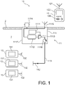
- the figure 1 schematically represents a first example of a turbojet engine parts inspection assembly according to the invention.
- the turbojet engine not shown, comprises a set of parts and/or components arranged in a nacelle compartment 1. This compartment is delimited by a nacelle wall 2 typically formed by a composite multilayer structure.
- the control assembly 10 comprises a control system 11, an interrogator device 12 and three RFID tags 13. Each RFID tag 13 is intended to be associated with a part or a component of the turbojet engine. It is for example glued, welded or otherwise attached to the part or component. It comprises an electronic chip 131 containing information relating to the part or the component with which it is associated and an antenna 132. The information relating to the part or the component relate for example to an identification of the part, to its lifespan or whether it contains one or more dangerous or toxic substances.
- the control system 11 comprises an interface device 111, an internal antenna 112 and a coaxial cable 113 connecting the interface device 111 to the internal antenna 112.
- the interface device 111 comprises an authorization module 1111, a conversion unit 1112, an amplifier repeater 1113, a BNC connector 1114, an external antenna 1115 and a circulator 1116.
- the authorization module 1111, the conversion unit 1112, the amplifier repeater 1113 and the circulator 1116 are housed in a box 1117 arranged at least partly in the nacelle compartment 1.
- the conversion unit 1112 is connected between, on the one hand, the BNC connector 1114 and the external antenna 1115 and, on the other hand, the amplifier repeater 1113.
- the conversion unit 1112 is thus arranged to convert a Wifi interrogation signal into an interrogation signal RFID and to convert an RFID response signal into a WiFi response signal.
- the amplifier repeater 1113 is connected between the conversion unit 1112 and the circulator 1116. It makes it possible to amplify the interrogation signal at the output of the conversion unit so that the internal antenna 112 emits an RFID signal powerful enough to reach all of the RFID tags 13.
- the circulator 1116 is connected between the amplifier repeater 1113 and the internal antenna 112.
- the authorization module 1111 is arranged to receive engine state information and prevent or authorize the transmission of an RF interrogation signal as a function of this information.
- the engine state information relates to the on or off state of the turbojet engine. It comes for example from a digital electronic control system with full engine authority, better known by the acronym FADEC for the English expression "Full Authority Digital Engine Control”.
- the authorization module 1111 controls the amplifier repeater 1113 so as to prevent the transmission of any RF interrogation signal by the internal antenna 112 when the turbojet engine is on and to amplify any RF signal from interrogation when the turbojet engine is off.
- the BNC connector 1114 and the external antenna 1115 are mounted on the casing 1117, so as to emerge outside the nacelle compartment 1. They form access points of the interface device 111, namely respectively a point wired access point and a wireless access point.
- the internal antenna 112 is arranged in the nacelle compartment 1, so as to be able to communicate with the RFID tags 13 without having to cross the nacelle wall 2. It is for example mounted on an internal surface of the nacelle wall 2. In the example of the figure 1 , the internal antenna 112 is a dipole antenna. Nevertheless, any type of antenna capable of transmitting and receiving radio frequency (RF) signals compatible with an RFID communication protocol can be used.
- RF radio frequency
- the interrogator device 12 also called “RFID reader”, comprises a wireless communication module equipped with an antenna 121 and arranged to communicate with the control system 11 via its external antenna 1115.
- the communication module is arranged to communicate with the control system 11 according to the first communication protocol, namely a WiFi protocol in this embodiment.
- the interrogator device 12 could also include a BNC connector able to be connected to the BNC connector 1114 of the interface device 111, for example via a coaxial cable.
- the interrogator device 12 is arranged to emit an interrogation signal intended for the RFID tags 13, so as to trigger the emission, by each RFID tag 13 having received this signal, of a response signal encoding information contained in its electronic chip 131.
- Interrogator device 12 also includes a display 122, control buttons 123 and a battery, not shown.
- the display 122 makes it possible to display the information collected in the RFID tags 13.
- the control buttons 123 make it possible to control the interrogator device 12.
- a button makes it possible to trigger the emission of an interrogation signal by the antenna 121.
- the battery is arranged to be able to power the various elements of the interrogator device 12 and make it autonomous.
- the interface device 111 could include a plurality of internal antennas, these antennas being arranged in different positions inside the nacelle compartment 1 in order to reach the different RFID tags 13 distributed in the turbojet engine.
- the interrogator device 12 operated with a communication protocol other than an RFID communication protocol.
- the interrogator device 12 could however operate with this protocol, making the presence of the conversion unit 1112 unnecessary.
- interface 111 by the BNC connector 1114 In this case, the power of this signal may already be sufficient to reach all the RFID tags 13.
- the authorization module 1111 can also be eliminated, in particular when the signal interrogation is injected into the interface device 111 by the BNC connector 1114, since an operator is authorized to approach the turbojet only if it is stopped.
- the picture 2 schematically represents, in a cross-sectional view, an aircraft turbojet engine 3 equipped with a second example of a parts inspection assembly according to the invention.
- the turbojet engine 3 comprises a core 31 formed by a set of parts and/or components arranged in a nacelle compartment 1 delimited by a nacelle wall 2.
- the control assembly 20 comprises a control system 21, an interrogator device 12 and four RFID tags 13.
- the interrogator device 12 and the RFID tags 13 are identical to those of the figure 1 .
- the control system 21 comprises an interface device 211, three internal antennas 212 and coaxial cables 213 connecting the internal antennas 212 to the interface device 211.
- the interface device 211 is similar to the interface device 111 described in reference to the figure 1 . It differs in that it comprises a BNC connector 2114 housed in the thickness of the nacelle wall 2 and an external antenna 2115 remote from the casing 2117 and connected to it by a coaxial cable 2118, preferably shielded.
- a turbojet engine parts control assembly can operate in the following manner.
- a user actuates a control button of the interrogator device 12 in order to emit an interrogation signal.
- This interrogation signal is received by the external antenna 1115, 2115, processed by the interface device 111, 211 and retransmitted by each internal antenna 112, 212.
- Each RFID tag 13 which receives this interrogation signal returns a signal response containing information relating to the turbojet part that it equips.
- This response signal is received by at least one internal antenna 112, 212, possibly converted by the conversion unit 1112 of the interface device 111, 211 and retransmitted by the external antenna 1115, 2115.
- the response signal is then received by the interrogator device 12 in order to extract the information from the RFID tags 13.
Landscapes
- Engineering & Computer Science (AREA)
- Physics & Mathematics (AREA)
- General Physics & Mathematics (AREA)
- Toxicology (AREA)
- Health & Medical Sciences (AREA)
- Theoretical Computer Science (AREA)
- Electromagnetism (AREA)
- General Engineering & Computer Science (AREA)
- Aviation & Aerospace Engineering (AREA)
- General Health & Medical Sciences (AREA)
- Artificial Intelligence (AREA)
- Computer Vision & Pattern Recognition (AREA)
- Computer Networks & Wireless Communication (AREA)
- Mechanical Engineering (AREA)
- Manufacturing & Machinery (AREA)
- Transportation (AREA)
- Arrangements For Transmission Of Measured Signals (AREA)
- Structures Of Non-Positive Displacement Pumps (AREA)
Description
- L'invention se situe dans le domaine de la maintenance des aéronefs et, plus précisément, dans le domaine du suivi des pièces montées dans un turboréacteur. Elle concerne un système de contrôle de pièces d'un turboréacteur dans lequel le contrôle s'effectue au moyen d'un dispositif interrogateur agencé pour pouvoir communiquer avec des étiquettes RFID associées auxdites pièces. L'invention concerne également un ensemble de contrôle comprenant un tel système de contrôle, au moins une étiquette RFID et un dispositif interrogateur. L'invention concerne enfin un turboréacteur d'aéronef comprenant le système de contrôle, au moins une étiquette RFID et un dispositif interrogateur.
- La maintenance d'un aéronef implique dans certaines situations d'identifier les pièces équipant un turboréacteur. Cette identification repose sur des informations relatives aux pièces telles que le nom du fabricant, le numéro de série, le numéro de pièce ou la date d'installation de la pièce. De manière conventionnelle, ces informations sont adjointes aux pièces équipant un turboréacteur par gravure de ces pièces ou par fixation d'une plaque d'identification. Après l'intégration des pièces dans le turboréacteur, la lecture des informations peut être difficile voire impossible sans démontage de ces pièces ou des pièces environnantes. En outre, les pièces d'un turboréacteur sont logées dans une nacelle et ne sont accessibles qu'après ouverture d'un capot. Une règlementation stricte encadre les interventions sur un turboréacteur et notamment l'ouverture de ces capots nacelle. Il est en particulier nécessaire de suivre un protocole spécifique impactant de manière négative la durée d'intervention. De plus, l'ouverture des capots nacelle peut être empêchée par des vents forts, rendant impossible l'identification des pièces.
- Une solution permettant d'accéder à des informations relatives aux pièces équipant un turboréacteur sans avoir à ouvrir de capot nacelle consiste à équiper les pièces d'étiquettes RFID contenant ces informations. Le passage d'un lecteur interrogateur au voisinage des étiquettes RFID permet de récolter les informations. L'échange de données est réalisé au moyen d'ondes électromagnétiques à des fréquences comprises entre environ 100 kHz (kilohertz) et quelques gigahertz. Un signal radiofréquence d'interrogation est d'abord émis par le lecteur interrogateur vers chacune des étiquettes RFID. Chaque étiquette RFID située dans un voisinage suffisamment proche du lecteur interrogateur pour recevoir le signal radiofréquence d'interrogation réémet à destination du lecteur interrogateur un signal radiofréquence de réponse contenant les informations contenues dans une puce de l'étiquette RFID. Cette solution basée sur la radio-identification permet d'accéder facilement et rapidement aux informations associées à une pluralité de pièces d'un turboréacteur, y compris lorsque ces pièces sont entourées d'autres pièces dans un environnement dense. Elle est notamment décrite dans la demande de brevet
EP 3 196 425 A1 comme solution pour communiquer à un appareil mobile externe à l'aéronef une information relative à un niveau d'huile dans une turbomachine. Néanmoins, l'échange de signaux électromagnétiques entre des pièces d'un turboréacteur et l'extérieur est fortement perturbé par la paroi de la nacelle enveloppant le turboréacteur. Cette paroi est généralement composée d'une structure multicouche au moins partiellement conductrice électriquement. Elle est par exemple formée par une première couche de composite carbone, une deuxième couche en nid d'abeille, une troisième couche de composite carbone et une quatrième couche en mailles de bronze. La paroi de la nacelle forme alors une cage de Faraday avec un affaiblissement de l'ordre de 40 à 80 dB. Cette barrière électromagnétique pourrait éventuellement être franchie en augmentant fortement la puissance des signaux échangés entre le lecteur interrogateur et les puces RFID. Toutefois, cette puissance doit être limitée en raison du risque d'interférences avec d'autres équipements de l'aéronef voire avec des équipements d'autres aéronefs. - La demande de brevet
US 2011/280279 A1 décrit un système de mesure de température par liaison sans fil pour environnement sévère. Le système de mesure peut être appliqué à la mesure de température au sein d'un turboréacteur, notamment sur une aube. Il comprend un émetteur, un capteur de température et un récepteur. Le capteur comprend une antenne, une couche diélectrique et une diode. La couche diélectrique est disposée sur un substrat pouvant notamment être une aube de turbine. Elle présente une constante diélectrique variable en fonction de la température. Lors de l'émission d'un signal d'interrogation au capteur, la composante de ce signal à la fréquence de résonance de l'ensemble antenne et couche diélectrique est réémise par l'antenne avec les harmoniques de cette fréquence. Le récepteur reçoit ce signal de réponse et détermine la température d'après la fréquence de résonance. - La demande de brevet
FR 3 053 958 A1 - La demande de brevet
US 2017/369188 A1 décrit un panneau composite à antenne intégrée pouvant être fixé sur un capot de soufflante. Il comprend une structure support, une antenne et un connecteur accessible du côté intérieur du panneau. Le connecteur est prévu pour connecter l'antenne à un capteur situé du côté intérieur du panneau, les informations du capteur étant envoyées à un dispositif externe. - La demande de brevet
US 2007/114280 A1 décrit un système d'identification de composants d'un aéronef et de suivi de maintenance par identification radiofréquence. Le système comprend des étiquettes RFID positionnées sur des composants de l'aéronef et un lecteur permettant de lire les étiquettes RFID. - Compte tenu de ce qui précède, l'invention a pour objectif de fournir une solution permettant d'identifier facilement des pièces d'un turboréacteur et éventuellement d'obtenir des informations supplémentaires relatives à ces pièces sans avoir à démonter une partie du turboréacteur et même sans avoir à ouvrir un capot de nacelle. L'invention a encore pour objectif de fournir un système dont les coûts de conception, de fabrication et de maintenance sont compatibles avec une utilisation à une échelle industrielle.
- À cet effet, l'invention repose sur la technologie de radio-identification, également appelée technologie RFID d'après l'expression anglo-saxonne « radio frequency identification ». Elle propose d'intégrer à la nacelle dans laquelle est logé le turboréacteur des éléments de liaison radiofréquences permettant de relayer des signaux radiofréquences entre l'intérieur de la nacelle et son environnement extérieur sans nécessiter une ouverture d'un capot de nacelle.
- Plus précisément, l'invention a pour objet un système de contrôle de pièces d'un turboréacteur, le turboréacteur étant logé dans un compartiment de nacelle délimité par une paroi de nacelle et comportant au moins une pièce équipée d'une étiquette RFID. Le système de contrôle comprend :
- ▪ une antenne interne logée dans le compartiment de nacelle, l'antenne interne étant agencée pour permettre l'échange de signaux radiofréquences avec l'étiquette RFID,
- ▪ un dispositif d'interface disposé au moins en partie dans le compartiment de nacelle et comportant un point d'accès disposé hors du compartiment de nacelle, le dispositif d'interface étant agencé pour pouvoir être connecté à un dispositif interrogateur agencé pour communiquer avec l'étiquette RFID, et
- ▪ une ligne de transmission connectant le dispositif d'interface à l'antenne interne.
- La communication entre un dispositif interrogateur, également appelé « lecteur RFID », et une étiquette RFID implique de manière conventionnelle la transmission, depuis le dispositif interrogateur vers l'étiquette RFID, d'un signal radiofréquence d'interrogation et la transmission, depuis l'étiquette RFID vers le dispositif interrogateur, d'un signal radiofréquence de réponse encodant des informations contenues dans une puce électronique de l'étiquette RFID. Les signaux radiofréquences présentent par exemple des fréquences dans une plage comprise entre 860 MHz (mégahertz) et 960 MHz. La technologie RFID peut être passive, active ou semi-active. Une étiquette RFID de technologie passive est uniquement alimentée par le signal électromagnétique émis par le dispositif interrogateur. Ce signal permet à la fois d'alimenter l'étiquette RFID et de lui transmettre une requête pour l'envoi des informations contenues dans une puce électronique de l'étiquette RFID. Une étiquette RFID de technologie active est équipée ou associée à une pile lui permettant de fournir l'énergie nécessaire à l'envoi d'un signal contenant les informations de la puce électronique. Une étiquette RFID de technologie semi-active est également équipée ou associée à une pile ; toutefois, l'énergie fournie par la pile est uniquement utilisée pour le stockage d'informations dans la puce électronique, et non pour l'émission du signal contenant ces informations.
- Il est à noter que le système de contrôle de pièces est adapté au contrôle simultané d'une pluralité de pièces équipées chacune d'une étiquette RFID. Afin de limiter les risques de collision entre les signaux radiofréquences de réponse émis par plusieurs étiquettes RFID, le système de contrôle peut intégrer un mécanisme de gestion de collision. Ce mécanisme consiste par exemple en un algorithme de gestion de collision intégré dans le dispositif interrogateur.
- L'antenne interne est par exemple montée sur une surface interne de la paroi de nacelle. Elle peut également être montée sur un carter du turboréacteur. Elle peut être de tout type dès lors qu'elle est adaptée à des signaux radiofréquences compatibles avec la technologie RFID. Il s'agit par exemple d'une antenne omnidirectionnelle, d'une antenne quart d'onde, d'une antenne dipolaire, d'une antenne à plan de sol, appelée « ground plane antenna » en anglais, d'une antenne parabolique ou d'une antenne quadriquad. Dans une forme particulière de réalisation, l'antenne interne est agencée pour émettre et recevoir des signaux radiofréquences dans une plage de fréquences comprise entre 860 MHz et 960 MHz.
- Selon une première variante de réalisation, le point d'accès du dispositif d'interface comprend un connecteur coaxial. Ce connecteur coaxial est accessible depuis l'extérieur du compartiment de nacelle. Il est par exemple monté sur la surface externe de la paroi de nacelle ou dans l'épaisseur de la paroi de nacelle. Le connecteur coaxial est par exemple un connecteur BNC.
- Selon une deuxième variante de réalisation, le point d'accès du dispositif d'interface comprend une antenne externe. Cette antenne externe est disposée à l'extérieur du compartiment de nacelle. Elle est par exemple montée sur la surface externe de la paroi de nacelle. L'antenne externe peut être de tout type, dès lors qu'elle est adaptée à des signaux radiofréquences compatibles avec la technologie RFID. Il s'agit par exemple d'une antenne omnidirectionnelle, d'une antenne quart d'onde, d'une antenne dipolaire, d'une antenne à plan de sol, d'une antenne parabolique ou d'une d'antenne quadriquad. Dans une forme particulière de réalisation, l'antenne externe est agencée pour émettre et recevoir des signaux radiofréquences dans une plage de fréquences UHF comprise entre 860 MHz et 960 MHz. Afin de limiter les perturbations aérodynamiques pendant le vol de l'aéronef, l'antenne externe peut être intégrée dans un boîtier présentant une forme aérodynamique monté sur la surface externe de la paroi de nacelle. Le boîtier présente par exemple une forme d'aileron de requin.
- Il est à noter que le dispositif d'interface peut comporter une pluralité de points d'accès. Par ailleurs, les première et deuxième variantes de réalisation sont tout à fait compatibles entre elles. Le dispositif d'interface peut comporter à la fois un ou plusieurs connecteurs coaxiaux ainsi qu'une ou plusieurs antennes externes. Dans une forme particulière de réalisation, le dispositif d'interface comporte un connecteur coaxial et une antenne externe. La connexion entre un dispositif interrogateur et l'antenne interne peut ainsi être réalisée par une liaison filaire ou par une liaison sans fil.
- Le dispositif d'interface peut comporter, en outre, une unité de conversion connectée entre l'antenne externe et l'antenne interne et agencée pour convertir un signal dans un premier protocole de communication en un signal dans un second protocole de communication, et inversement, le premier protocole de communication étant compatible avec le dispositif interrogateur et le second protocole de communication étant compatible avec l'étiquette RFID. En particulier, l'unité de conversion peut être agencée pour convertir, d'une part, un signal radiofréquence d'interrogation émis par le dispositif interrogateur dans le premier protocole de communication en un signal radiofréquence d'interrogation dans le second protocole de communication et, d'autre part, un signal radiofréquence de réponse émis par l'étiquette RFID dans le second protocole de communication en un signal radiofréquence de réponse dans le premier protocole d'interrogation. De manière générale, le second protocole de communication est un protocole de communication RFID. Le premier protocole de communication peut notamment être un protocole Wifi, un protocole Bluetooth, un protocole Zigbee ou un protocole propriétaire.
- Le système de contrôle peut comporter, en outre, une antenne relais installée au sol, agencée pour transmettre des signaux radiofréquences provenant d'un dispositif interrogateur vers l'antenne externe du dispositif d'interface, et réciproquement. Le système de contrôle peut comporter une pluralité d'antennes relais, chaque antenne relais étant avantageusement disposée à proximité d'une zone de parking d'un aéronef, à proximité d'un hangar pour aéronef ou à l'intérieur d'un tel hangar. Un même dispositif interrogateur peut alors être utilisé pour interroger, depuis un unique emplacement, ou depuis un nombre limité d'emplacements, une pluralité de turboréacteurs équipant différents aéronefs.
- Selon une forme particulière de réalisation, le dispositif d'interface comporte, en outre, un répéteur amplificateur bidirectionnel connecté entre l'antenne externe et l'antenne interne. En cas de pluralités d'antennes internes, le répéteur amplificateur peut être connecté au niveau d'une branche commune des lignes de transmission, de manière à amplifier les signaux parcourant l'ensemble des lignes de transmission. Le répéteur amplificateur est avantageusement agencé pour, d'une part, recevoir un signal radiofréquence d'interrogation émis par le dispositif interrogateur, l'amplifier et l'envoyer vers l'antenne interne et, d'autre, recevoir un signal radiofréquence de réponse émis par l'étiquette RFID, l'amplifier et l'envoyer vers l'antenne externe.
- Selon une autre forme particulière de réalisation, le dispositif d'interface comporte, en outre, un module d'autorisation agencé pour recevoir une information d'état moteur relative à l'état allumé ou éteint du turboréacteur et empêcher ou autoriser l'émission d'un signal radiofréquence d'interrogation par l'antenne interne en fonction de ladite information d'état moteur. Cette forme de réalisation est particulièrement appropriée pour la deuxième variante de réalisation, dans laquelle le point d'accès comporte une antenne externe susceptible de recevoir un signal radiofréquence d'interrogation alors que le turboréacteur est en fonctionnement. La transmission de ce signal radiofréquence dans le compartiment de nacelle risque de perturber certains signaux circulant au sein du turboréacteur et participant à sa régulation. Pour la première variante de réalisation, dans laquelle le point d'accès comporte un connecteur coaxial, le risque d'émission d'un signal radiofréquence d'interrogation est déjà limité par la règlementation qui interdit à un opérateur d'approcher d'un turboréacteur en fonctionnement. Néanmoins, un module d'autorisation peut être prévu afin d'assurer une sécurité supplémentaire. L'état allumé ou éteint du turboréacteur correspond par exemple à une vitesse de rotation du turboréacteur, le turboréacteur étant considéré comme éteint lorsque sa vitesse de rotation est nulle et étant considéré comme allumé lorsque sa vitesse de rotation est non nulle. L'information d'état moteur peut être émise par un système de commande de l'aéronef, par exemple un système central de commande ou un système de régulation électronique numérique à pleine autorité du moteur, mieux connu sous l'acronyme FADEC pour l'expression anglo-saxonne « Full Authority Digital Engine Control ».
- L'étiquette RFID peut contenir une information relative à une identification de la pièce qu'elle équipe, une information relative à une durée de vie de ladite pièce et/ou une information relative à la présence d'une substance prédéterminée dans ladite pièce. L'étiquette RFID peut notamment contenir un numéro de série, un numéro de produit, une indication relative au fabricant, une durée de vie estimée de la pièce, une date de remplacement prévu de la pièce et/ou une information relative à la présence d'une substance dangereuse ou toxique.
- La paroi de nacelle comporte typiquement un capot de soufflante et un capot de coeur. Le point d'accès du dispositif d'interface peut alors être monté sur le capot de soufflante ou le capot de coeur. Plus précisément, il peut être monté sur une surface externe du capot de soufflante ou du capot de coeur.
- Le système de contrôle peut comporter une pluralité d'antennes internes logées dans le compartiment de nacelle et une pluralité de lignes de transmission, les lignes de transmission connectant le dispositif d'interface à chaque antenne interne. Les antennes internes sont de préférence disposées en différentes positions à l'intérieur du compartiment de nacelle. Chaque antenne interne est connectée à au moins un point d'accès par une ligne de transmission. De préférence, chaque antenne interne est connectée à l'ensemble des points d'accès. Ainsi, depuis un même point d'accès, des étiquettes RFID disposées en différentes positions du turboréacteur peuvent être interrogées.
- Chaque ligne de transmission assure la connexion électrique entre un point d'accès et une antenne interne. Plusieurs lignes de transmission peuvent comporter un tronçon commun afin de limiter leur longueur totale et donc le poids du système de contrôle. En particulier, un tronçon commun peut être prévu pour traverser la paroi de nacelle. Dans une forme particulière de réalisation, chaque ligne de transmission comprend un câble coaxial. De préférence, le câble coaxial est blindé.
- L'invention a également pour objet un ensemble de contrôle de pièces d'un turboréacteur comprenant le système de contrôle de pièces tel que décrit précédemment, une ou plusieurs étiquettes RFID chacune apte à équiper une pièce du turboréacteur et un dispositif interrogateur agencé pour communiquer avec les étiquettes RFID via le système de contrôle.
- L'invention a encore pour objet un turboréacteur d'aéronef agencé pour être logé dans un compartiment de nacelle délimité par une paroi de nacelle et comprenant le système de contrôle de pièces tel que décrit précédemment et une ou plusieurs étiquettes RFID équipant chacune une pièce du turboréacteur.
- D'autres caractéristiques, détails et avantages de l'invention ressortiront à la lecture de la description qui va suivre, donnée uniquement à titre d'exemple et faite en référence aux dessins annexés pour lesquels :
- la
figure 1 représente schématiquement un premier exemple d'ensemble de contrôle de pièces d'un turboréacteur selon l'invention ; - la
figure 2 représente schématiquement, dans une vue en coupe transversale, un turboréacteur d'aéronef équipé d'un deuxième exemple d'ensemble de contrôle de pièces selon l'invention. - La
figure 1 représente schématiquement un premier exemple d'ensemble de contrôle de pièces d'un turboréacteur selon l'invention. Le turboréacteur, non représenté, comprend un ensemble de pièces et/ou de composants disposés dans un compartiment de nacelle 1. Ce compartiment est délimité par une paroi de nacelle 2 typiquement formée par une structure multicouche composite. L'ensemble de contrôle 10 comporte un système de contrôle 11, un dispositif interrogateur 12 et trois étiquettes RFID 13. Chaque étiquette RFID 13 est destinée à être associée à une pièce ou à un composant du turboréacteur. Elle est par exemple collée, soudée ou autrement fixée à la pièce ou au composant. Elle comprend une puce électronique 131 contenant des informations relatives à la pièce ou au composant auquel elle est associée et une antenne 132. Les informations relatives à la pièce ou au composant portent par exemple sur une identification de la pièce, sur sa durée de vie ou sur le fait qu'elle contient une ou plusieurs substances dangereuses ou toxiques. - Le système de contrôle 11 comprend un dispositif d'interface 111, une antenne interne 112 et un câble coaxial 113 connectant le dispositif d'interface 111 à l'antenne interne 112. Le dispositif d'interface 111 comporte un module d'autorisation 1111, une unité de conversion 1112, un répéteur amplificateur 1113, un connecteur BNC 1114, une antenne externe 1115 et un circulateur 1116. Le module d'autorisation 1111, l'unité de conversion 1112, le répéteur amplificateur 1113 et le circulateur 1116 sont logés dans un boîtier 1117 disposé au moins en partie dans le compartiment de nacelle 1. L'unité de conversion 1112 est connectée entre, d'une part, le connecteur BNC 1114 et l'antenne externe 1115 et, d'autre part, le répéteur amplificateur 1113. Elle est agencée pour convertir un signal dans un premier protocole de communication en un signal dans un second protocole de communication, et inversement. Le premier protocole de communication est compatible avec le dispositif interrogateur 12. Il s'agit par exemple du protocole Wifi. Le second protocole de communication est un protocole de communication RFID compatible avec les étiquettes RFID 13. L'unité de conversion 1112 est ainsi agencée pour convertir un signal d'interrogation Wifi en un signal d'interrogation RFID et pour convertir un signal de réponse RFID en un signal de réponse Wifi. Le répéteur amplificateur 1113 est connecté entre l'unité de conversion 1112 et le circulateur 1116. Il permet d'amplifier le signal d'interrogation en sortie de l'unité de conversion de façon à ce que l'antenne interne 112 émette un signal RFID suffisamment puissant pour atteindre l'ensemble des étiquettes RFID 13. Le circulateur 1116 est connecté entre le répéteur amplificateur 1113 et l'antenne interne 112. Il permet à tout signal de réponse provenant de l'antenne interne 112 de contourner le répéteur amplificateur 1113 et d'être injecté directement dans l'unité de conversion 1112. Le module d'autorisation 1111 est agencé pour recevoir une information d'état moteur et empêcher ou autoriser l'émission d'un signal RF d'interrogation en fonction de cette information. L'information d'état moteur est relative à l'état allumé ou éteint du turboréacteur. Elle provient par exemple d'un système de régulation électronique numérique à pleine autorité du moteur, mieux connu sous l'acronyme FADEC pour l'expression anglo-saxonne « Full Authority Digital Engine Control ». Dans cet exemple de réalisation, le module d'autorisation 1111 pilote le répéteur amplificateur 1113 de manière à empêcher l'émission de tout signal RF d'interrogation par l'antenne interne 112 lorsque le turboréacteur est allumé et à amplifier tout signal RF d'interrogation lorsque le turboréacteur est éteint. Le connecteur BNC 1114 et l'antenne externe 1115 sont montés sur le boîtier 1117, de manière à déboucher à l'extérieur du compartiment de nacelle 1. Ils forment des points d'accès du dispositif d'interface 111, à savoir respectivement un point d'accès filaire et un point d'accès sans fil. L'antenne interne 112 est disposée dans le compartiment de nacelle 1, de manière à pouvoir communiquer avec les étiquettes RFID 13 sans avoir à traverser la paroi de nacelle 2. Elle est par exemple montée sur une surface interne de la paroi de nacelle 2. Dans l'exemple de la
figure 1 , l'antenne interne 112 est une antenne dipolaire. Néanmoins, tout type d'antenne apte à émettre et recevoir des signaux radiofréquences (RF) compatibles avec un protocole de communication RFID peut être utilisé. - Le dispositif interrogateur 12, également appelé « lecteur RFID », comprend un module de communication sans fil équipé d'une antenne 121 et agencé pour communiquer avec le système de contrôle 11 via son antenne externe 1115. Le module de communication est agencé pour communiquer avec le système de contrôle 11 selon le premier protocole de communication, à savoir un protocole Wifi dans cet exemple de réalisation. Le dispositif interrogateur 12 pourrait également comporter un connecteur BNC apte à être connecté au connecteur BNC 1114 du dispositif d'interface 111, par exemple par l'intermédiaire d'un câble coaxial. Le dispositif interrogateur 12 est agencé pour émettre un signal d'interrogation à destination des étiquettes RFID 13, de manière à déclencher l'émission, par chaque étiquette RFID 13 ayant reçu ce signal, d'un signal de réponse encodant des informations contenues dans sa puce électronique 131. Le dispositif interrogateur 12 comporte également un afficheur 122, des boutons de commande 123 et une batterie, non représentée. L'afficheur 122 permet d'afficher les informations récoltées dans les étiquettes RFID 13. Les boutons de commande 123 permettent de commander le dispositif interrogateur 12. En particulier, un bouton permet de déclencher l'émission d'un signal d'interrogation par l'antenne 121. La batterie est agencée pour pouvoir alimenter les différents éléments du dispositif interrogateur 12 et le rendre autonome.
- Il est à noter que le dispositif d'interface 111 pourrait comporter une pluralité d'antennes internes, ces antennes étant disposées en différentes positions à l'intérieur du compartiment de nacelle 1 afin d'atteindre les différentes étiquettes RFID 13 réparties dans le turboréacteur. Par ailleurs, il a été considéré, dans l'exemple de réalisation de la
figure 1 , que le dispositif interrogateur 12 fonctionnait avec un protocole de communication autre qu'un protocole de communication RFID. Le dispositif interrogateur 12 pourrait cependant fonctionner avec ce protocole, rendant inutile la présence de l'unité de conversion 1112. Le répéteur amplificateur 1113 et le circulateur 1116 pourraient également être supprimés, notamment lorsque le signal d'interrogation est injecté dans le dispositif d'interface 111 par le connecteur BNC 1114. Dans ce cas, la puissance de ce signal peut être déjà suffisante pour atteindre toutes les étiquettes RFID 13. Le module d'autorisation 1111 peut aussi être supprimé, notamment lorsque le signal d'interrogation est injecté dans le dispositif d'interface 111 par le connecteur BNC 1114, puisqu'un opérateur n'est autorisé à approcher le turboréacteur que s'il est à l'arrêt. - La
figure 2 représente schématiquement, dans une vue en coupe transversale, un turboréacteur d'aéronef 3 équipé d'un deuxième exemple d'ensemble de contrôle de pièces selon l'invention. Le turboréacteur 3 comporte un coeur 31 formé par un ensemble de pièces et/ou de composants disposés dans un compartiment de nacelle 1 délimité par une paroi de nacelle 2. L'ensemble de contrôle 20 comporte un système de contrôle 21, un dispositif interrogateur 12 et quatre étiquettes RFID 13. Le dispositif interrogateur 12 et les étiquettes RFID 13 sont identiques à ceux de lafigure 1 . Le système de contrôle 21 comprend un dispositif d'interface 211, trois antennes internes 212 et des câbles coaxiaux 213 reliant les antennes internes 212 au dispositif d'interface 211. Le dispositif d'interface 211 est analogue au dispositif d'interface 111 décrit en référence à lafigure 1 . Il s'en distingue en ce qu'il comporte un connecteur BNC 2114 logé dans l'épaisseur de la paroi de nacelle 2 et une antenne externe 2115 déportée du boîtier 2117 et reliée à lui par un câble coaxial 2118, de préférence blindé. - Les exemples d'ensemble de contrôle de pièces d'un turboréacteur selon l'invention peuvent fonctionner de la manière suivante. Dans une première étape, un utilisateur actionne un bouton de commande du dispositif interrogateur 12 afin d'émettre un signal d'interrogation. Ce signal d'interrogation est reçu par l'antenne externe 1115, 2115, traité par le dispositif d'interface 111, 211 et réémis par chaque antenne interne 112, 212. Chaque étiquette RFID 13 qui reçoit ce signal d'interrogation renvoie un signal de réponse contenant des informations relatives à la pièce de turboréacteur qu'elle équipe. Ce signal de réponse est reçu par au moins une antenne interne 112, 212, éventuellement converti par l'unité de conversion 1112 du dispositif d'interface 111, 211 et réémis par l'antenne externe 1115, 2115. Le signal de réponse est alors reçu par le dispositif interrogateur 12 afin d'en extraire les informations issues des étiquettes RFID 13.
Claims (12)
- Système de contrôle de pièces d'un turboréacteur, le turboréacteur (3) étant logé dans un compartiment de nacelle (1) délimité par une paroi de nacelle (2) et comportant au moins une pièce équipée d'une étiquette RFID (13), le système de contrôle (11, 12) étant caractérisé en ce qu'il comprend :▪ une antenne interne (112, 212) logée dans le compartiment de nacelle (1), l'antenne interne étant agencée pour permettre l'échange de signaux radiofréquences avec l'étiquette RFID (13),▪ un dispositif d'interface (111, 211) disposé au moins en partie dans le compartiment de nacelle et comportant un point d'accès (1114, 1115, 2114, 2115) disposé hors du compartiment de nacelle, le dispositif d'interface étant agencé pour pouvoir être connecté à un dispositif interrogateur (12) agencé pour communiquer avec l'étiquette RFID, et▪ une ligne de transmission (113, 213) connectant le dispositif d'interface (111, 211) à l'antenne interne (112, 212).
- Système de contrôle selon la revendication 1, dans lequel le point d'accès du dispositif d'interface comprend un connecteur coaxial (1114, 2114).
- Système de contrôle selon l'une des revendications 1 et 2, dans lequel le point d'accès du dispositif d'interface comprend une antenne externe (1115, 2115).
- Système de contrôle selon la revendication 3, dans lequel le dispositif d'interface (111, 211) comporte, en outre, une unité de conversion (1112) connectée entre l'antenne externe (1115, 2115) et l'antenne interne (112, 212) et agencée pour convertir un signal dans un premier protocole de communication en un signal dans un second protocole de communication, et inversement, le premier protocole de communication étant compatible avec le dispositif interrogateur (12) et le second protocole de communication étant compatible avec l'étiquette RFID (13).
- Système de contrôle selon l'une des revendications 3 et 4, comprenant en outre une antenne relais installée au sol, agencée pour transmettre des signaux radiofréquences provenant d'un dispositif interrogateur (12) vers l'antenne externe (1115, 2115) du dispositif d'interface, et réciproquement.
- Système de contrôle selon l'une des revendications précédentes, dans lequel le dispositif d'interface (111, 211) comporte, en outre, un répéteur amplificateur (1113) bidirectionnel connecté entre l'antenne externe (1115, 2115) et l'antenne interne (112, 212).
- Système de contrôle selon l'une des revendications précédentes, dans lequel le dispositif d'interface (111, 211) comporte, en outre, un module d'autorisation (1111) agencé pour recevoir une information d'état moteur relative à l'état allumé ou éteint du turboréacteur et empêcher ou autoriser l'émission d'un signal radiofréquence d'interrogation par l'antenne interne (112, 212) en fonction de ladite information d'état moteur.
- Système de contrôle selon l'une des revendications précédentes, dans lequel l'étiquette RFID (13) contient une information relative à une identification de la pièce qu'elle équipe, une information relative à une durée de vie de ladite pièce et/ou une information relative à la présence d'une substance prédéterminée dans ladite pièce.
- Système de contrôle selon l'une des revendications précédentes dans lequel, la paroi de nacelle (2) comportant un capot de soufflante et un capot de coeur, le point d'accès (1114, 1115, 2114, 2115) du dispositif d'interface est monté sur le capot de soufflante ou le capot de coeur.
- Système de contrôle selon l'une des revendications précédentes, comprenant une pluralité d'antennes internes (212) logées dans le compartiment de nacelle (1) et une pluralité de lignes de transmission (213), les lignes de transmission connectant le dispositif d'interface (211) à chaque antenne interne (212).
- Ensemble de contrôle de pièces d'un turboréacteur caractérisé en ce qu'il comprend un système de contrôle (11, 21) selon l'une des revendications 1 à 10, une étiquette RFID (13) apte à équiper une pièce d'un turboréacteur (3) et un dispositif interrogateur (12) agencé pour communiquer avec l'étiquette RFID via le système de contrôle.
- Turboréacteur d'aéronef agencé pour être logé dans un compartiment de nacelle (1) délimité par une paroi de nacelle (2) et caractérisé en ce qu'il comprend un système de contrôle (11, 21) selon l'une des revendications 1 à 10 et une étiquette RFID (13) équipant une pièce du turboréacteur.
Applications Claiming Priority (2)
| Application Number | Priority Date | Filing Date | Title |
|---|---|---|---|
| FR1857170A FR3084762B1 (fr) | 2018-07-31 | 2018-07-31 | Systeme de controle de pieces d'un turboreacteur par identification radiofrequence avec antenne integree |
| PCT/FR2019/051833 WO2020025881A1 (fr) | 2018-07-31 | 2019-07-24 | Système de contrôle de pièces d'un turboréacteur par identification radiofréquence avec antenne intégrée |
Publications (2)
| Publication Number | Publication Date |
|---|---|
| EP3811278A1 EP3811278A1 (fr) | 2021-04-28 |
| EP3811278B1 true EP3811278B1 (fr) | 2022-12-21 |
Family
ID=65200970
Family Applications (1)
| Application Number | Title | Priority Date | Filing Date |
|---|---|---|---|
| EP19790632.4A Active EP3811278B1 (fr) | 2018-07-31 | 2019-07-24 | Système de contrôle de pièces d'un turboréacteur par identification radiofréquence avec antenne intégrée |
Country Status (5)
| Country | Link |
|---|---|
| US (1) | US12002298B2 (fr) |
| EP (1) | EP3811278B1 (fr) |
| CN (1) | CN112470162A (fr) |
| FR (1) | FR3084762B1 (fr) |
| WO (1) | WO2020025881A1 (fr) |
Families Citing this family (3)
| Publication number | Priority date | Publication date | Assignee | Title |
|---|---|---|---|---|
| CN114694441B (zh) * | 2020-12-31 | 2023-07-21 | 航宇伟创科技(北京)有限公司 | 一种机载自卫干扰吊舱维修训练模拟舱 |
| FR3132083B1 (fr) * | 2022-01-27 | 2024-07-12 | Safran Aircraft Engines | Procédé de gestion d’équipements de turbomachine par lecteur embarqué de type radio-identification |
| FR3149730A1 (fr) * | 2023-06-12 | 2024-12-13 | Safran Nacelles | Dispositif radiofréquence multi-antennes comprenant une antenne de récupération d’énergie |
Family Cites Families (22)
| Publication number | Priority date | Publication date | Assignee | Title |
|---|---|---|---|---|
| US7911324B2 (en) * | 2001-02-16 | 2011-03-22 | Automotive Technologies International, Inc. | Method and system for obtaining information about RFID-equipped objects |
| US20050198967A1 (en) * | 2002-09-23 | 2005-09-15 | Siemens Westinghouse Power Corp. | Smart component for use in an operating environment |
| US8004423B2 (en) * | 2004-06-21 | 2011-08-23 | Siemens Energy, Inc. | Instrumented component for use in an operating environment |
| US20070001809A1 (en) * | 2005-05-02 | 2007-01-04 | Intermec Ip Corp. | Method and system for reading objects having radio frequency identification (RFID) tags inside enclosures |
| US7551086B2 (en) * | 2005-09-20 | 2009-06-23 | The Boeing Company | System and methods for tracking aircraft components |
| US7368827B2 (en) * | 2006-09-06 | 2008-05-06 | Siemens Power Generation, Inc. | Electrical assembly for monitoring conditions in a combustion turbine operating environment |
| US7969323B2 (en) * | 2006-09-14 | 2011-06-28 | Siemens Energy, Inc. | Instrumented component for combustion turbine engine |
| US8565998B2 (en) * | 2006-11-27 | 2013-10-22 | United Technologies Corporation | Gas turbine engine having on-engine data storage device |
| FR2927210B1 (fr) * | 2008-02-01 | 2010-02-26 | Airbus France | Dispositif de commutation adapte a commuter un reseau sans fil d'aeronef d'une configuration de maintenance a une configuration commerciale et reciproquement. |
| US8662746B2 (en) * | 2008-08-01 | 2014-03-04 | Siemens, Energy Inc. | Turbine component instrumented to provide thermal measurements |
| US9189769B2 (en) * | 2009-12-07 | 2015-11-17 | Meps Real-Time, Inc. | Real-time inventory re-supply system |
| US8348504B2 (en) | 2010-05-12 | 2013-01-08 | Wireless Sensor Technologies, Llc | Wireless temperature measurement system and methods of making and using same |
| US8229605B2 (en) * | 2010-05-13 | 2012-07-24 | Embedded Control Systems Inc. | Aviation application setting antenna array and integrated temperature sensor |
| FR2998390B1 (fr) * | 2014-02-06 | 2017-06-16 | Aircelle Sa | Utilisation d'un code comme marquage d'une nacelle. |
| US9350319B2 (en) * | 2014-02-24 | 2016-05-24 | Siemens Energy, Inc. | Self-powered sensing and transmitting device and method of fabricating the same |
| BE1023406B1 (fr) | 2016-01-21 | 2017-03-09 | Safran Aero Boosters S.A. | Turbomachine d'aéronef |
| FR3050876B1 (fr) * | 2016-04-28 | 2019-07-05 | Turbomeca | Capot pour moteur d'aeronef comprenant une antenne de lecteur de radio-identification |
| US9972896B2 (en) * | 2016-06-23 | 2018-05-15 | General Electric Company | Wireless aircraft engine monitoring system |
| US10371588B2 (en) * | 2016-07-01 | 2019-08-06 | Rhode Island Council On Postsecondary Education | High resolution strain gages for ceramic matrix composites and methods of manufacture thereof |
| FR3053958B1 (fr) * | 2016-07-13 | 2019-06-28 | Airbus | Panneau equipe pour un aeronef et comportant une antenne rfid et un lecteur rfid |
| FR3084763B1 (fr) * | 2018-07-31 | 2020-08-14 | Safran Aircraft Engines | Systeme de controle de pieces d'un turboreacteur par identification radiofrequence |
| US11448085B2 (en) * | 2019-11-11 | 2022-09-20 | Raytheon Technologies Corporation | Remote temperature measurement system for gas turbine engine |
-
2018
- 2018-07-31 FR FR1857170A patent/FR3084762B1/fr active Active
-
2019
- 2019-07-24 WO PCT/FR2019/051833 patent/WO2020025881A1/fr not_active Ceased
- 2019-07-24 CN CN201980049193.0A patent/CN112470162A/zh active Pending
- 2019-07-24 EP EP19790632.4A patent/EP3811278B1/fr active Active
- 2019-07-24 US US17/264,074 patent/US12002298B2/en active Active
Also Published As
| Publication number | Publication date |
|---|---|
| FR3084762B1 (fr) | 2020-08-14 |
| EP3811278A1 (fr) | 2021-04-28 |
| US12002298B2 (en) | 2024-06-04 |
| CN112470162A (zh) | 2021-03-09 |
| WO2020025881A1 (fr) | 2020-02-06 |
| FR3084762A1 (fr) | 2020-02-07 |
| US20210375071A1 (en) | 2021-12-02 |
Similar Documents
| Publication | Publication Date | Title |
|---|---|---|
| EP3811278B1 (fr) | Système de contrôle de pièces d'un turboréacteur par identification radiofréquence avec antenne intégrée | |
| EP3811279B1 (fr) | Système de contrôle de pièces d'un turboréacteur par identification radiofréquence | |
| EP4062488B1 (fr) | Dispositif de détection d'éléments d'identification à métasurface(s) relais, pour un système | |
| EP2922144B1 (fr) | Radar secondaire bi-fonction, et système radar comportant un tel radar | |
| EP1956216A1 (fr) | Installation de commande de turbomachine équipée d'un système de vérification d'équipement à puce passive d'identification par radiofréquence | |
| CA2937510C (fr) | Dispositif de communication d'une cabine d'aeronef | |
| FR3050876B1 (fr) | Capot pour moteur d'aeronef comprenant une antenne de lecteur de radio-identification | |
| CA3098211A1 (fr) | Enveloppe pneumatique equipee d'un systeme de mesure et methode de communication d'un tel assemblage | |
| EP1952366B1 (fr) | Dispositif et procédé de surveillance d'un objet sensible tel qu'un aeronef | |
| FR3099918A1 (fr) | Dispositif de contrôle pour suivi du transport de turbomachines sur un véhicule, véhicule, procédé, et installation de suivi correspondants | |
| EP2574908A1 (fr) | Dispositif de mesure de permittivité électrique sans fil et procédés mettant en oeuvre un tel dispositif | |
| FR3116229A1 (fr) | Pièce composite, notamment pour une turbomachine d’aéronef | |
| WO2019081738A1 (fr) | Systeme de mesure de parametre d'un ensemble monte | |
| CN213042321U (zh) | 巡检系统 | |
| FR2948194A1 (fr) | Systeme radar complementaire pour la detection de cibles evoluant dans un champ d'eoliennes | |
| FR3030848B1 (fr) | Dispositif de surveillance et infrastructure de surveillance associee | |
| FR3123891A1 (fr) | Système embarqué de détection d’impacts sur le fuselage d’un aéronef | |
| EP3198886A1 (fr) | Architecture d'observation d'une pluralité d'objets disposés dans des endroits géographiques distincts et procédé de collecte de données d'observation associé | |
| EP4286820A1 (fr) | Système de détection de fuite de fluide de refroidissement dans un équipement électronique | |
| WO2004079918A2 (fr) | Dispositif d’emission et/ou de reception et systeme de securisation integrant un tel dispositif | |
| FR3117547A1 (fr) | Système et procédé de détermination de la configuration d’une turbomachine | |
| FR3103211A1 (fr) | Système embarqué modulaire d’enregistrement et de déchargement de données d’un calculateur d’une turbomachine | |
| FR3101330A1 (fr) | Drone pour la localisation de personne recherchée et procédé associé | |
| FR2714484A1 (fr) | Système interrogateur associé à un radar aéroporté. | |
| FR3091683A1 (fr) | Dispositif de protection d’un coffre de traction d’un vehicule et vehicule associe |
Legal Events
| Date | Code | Title | Description |
|---|---|---|---|
| STAA | Information on the status of an ep patent application or granted ep patent |
Free format text: STATUS: UNKNOWN |
|
| STAA | Information on the status of an ep patent application or granted ep patent |
Free format text: STATUS: THE INTERNATIONAL PUBLICATION HAS BEEN MADE |
|
| PUAI | Public reference made under article 153(3) epc to a published international application that has entered the european phase |
Free format text: ORIGINAL CODE: 0009012 |
|
| STAA | Information on the status of an ep patent application or granted ep patent |
Free format text: STATUS: REQUEST FOR EXAMINATION WAS MADE |
|
| 17P | Request for examination filed |
Effective date: 20210122 |
|
| AK | Designated contracting states |
Kind code of ref document: A1 Designated state(s): AL AT BE BG CH CY CZ DE DK EE ES FI FR GB GR HR HU IE IS IT LI LT LU LV MC MK MT NL NO PL PT RO RS SE SI SK SM TR |
|
| AX | Request for extension of the european patent |
Extension state: BA ME |
|
| DAV | Request for validation of the european patent (deleted) | ||
| DAX | Request for extension of the european patent (deleted) | ||
| GRAP | Despatch of communication of intention to grant a patent |
Free format text: ORIGINAL CODE: EPIDOSNIGR1 |
|
| STAA | Information on the status of an ep patent application or granted ep patent |
Free format text: STATUS: GRANT OF PATENT IS INTENDED |
|
| INTG | Intention to grant announced |
Effective date: 20220715 |
|
| GRAS | Grant fee paid |
Free format text: ORIGINAL CODE: EPIDOSNIGR3 |
|
| GRAA | (expected) grant |
Free format text: ORIGINAL CODE: 0009210 |
|
| STAA | Information on the status of an ep patent application or granted ep patent |
Free format text: STATUS: THE PATENT HAS BEEN GRANTED |
|
| AK | Designated contracting states |
Kind code of ref document: B1 Designated state(s): AL AT BE BG CH CY CZ DE DK EE ES FI FR GB GR HR HU IE IS IT LI LT LU LV MC MK MT NL NO PL PT RO RS SE SI SK SM TR |
|
| REG | Reference to a national code |
Ref country code: GB Ref legal event code: FG4D Free format text: NOT ENGLISH |
|
| REG | Reference to a national code |
Ref country code: DE Ref legal event code: R096 Ref document number: 602019023468 Country of ref document: DE |
|
| REG | Reference to a national code |
Ref country code: CH Ref legal event code: EP |
|
| REG | Reference to a national code |
Ref country code: AT Ref legal event code: REF Ref document number: 1539497 Country of ref document: AT Kind code of ref document: T Effective date: 20230115 |
|
| REG | Reference to a national code |
Ref country code: IE Ref legal event code: FG4D Free format text: LANGUAGE OF EP DOCUMENT: FRENCH |
|
| REG | Reference to a national code |
Ref country code: LT Ref legal event code: MG9D |
|
| REG | Reference to a national code |
Ref country code: NL Ref legal event code: MP Effective date: 20221221 |
|
| PG25 | Lapsed in a contracting state [announced via postgrant information from national office to epo] |
Ref country code: SE Free format text: LAPSE BECAUSE OF FAILURE TO SUBMIT A TRANSLATION OF THE DESCRIPTION OR TO PAY THE FEE WITHIN THE PRESCRIBED TIME-LIMIT Effective date: 20221221 Ref country code: NO Free format text: LAPSE BECAUSE OF FAILURE TO SUBMIT A TRANSLATION OF THE DESCRIPTION OR TO PAY THE FEE WITHIN THE PRESCRIBED TIME-LIMIT Effective date: 20230321 Ref country code: LT Free format text: LAPSE BECAUSE OF FAILURE TO SUBMIT A TRANSLATION OF THE DESCRIPTION OR TO PAY THE FEE WITHIN THE PRESCRIBED TIME-LIMIT Effective date: 20221221 Ref country code: FI Free format text: LAPSE BECAUSE OF FAILURE TO SUBMIT A TRANSLATION OF THE DESCRIPTION OR TO PAY THE FEE WITHIN THE PRESCRIBED TIME-LIMIT Effective date: 20221221 |
|
| REG | Reference to a national code |
Ref country code: AT Ref legal event code: MK05 Ref document number: 1539497 Country of ref document: AT Kind code of ref document: T Effective date: 20221221 |
|
| PG25 | Lapsed in a contracting state [announced via postgrant information from national office to epo] |
Ref country code: RS Free format text: LAPSE BECAUSE OF FAILURE TO SUBMIT A TRANSLATION OF THE DESCRIPTION OR TO PAY THE FEE WITHIN THE PRESCRIBED TIME-LIMIT Effective date: 20221221 Ref country code: LV Free format text: LAPSE BECAUSE OF FAILURE TO SUBMIT A TRANSLATION OF THE DESCRIPTION OR TO PAY THE FEE WITHIN THE PRESCRIBED TIME-LIMIT Effective date: 20221221 Ref country code: HR Free format text: LAPSE BECAUSE OF FAILURE TO SUBMIT A TRANSLATION OF THE DESCRIPTION OR TO PAY THE FEE WITHIN THE PRESCRIBED TIME-LIMIT Effective date: 20221221 Ref country code: GR Free format text: LAPSE BECAUSE OF FAILURE TO SUBMIT A TRANSLATION OF THE DESCRIPTION OR TO PAY THE FEE WITHIN THE PRESCRIBED TIME-LIMIT Effective date: 20230322 |
|
| PG25 | Lapsed in a contracting state [announced via postgrant information from national office to epo] |
Ref country code: NL Free format text: LAPSE BECAUSE OF FAILURE TO SUBMIT A TRANSLATION OF THE DESCRIPTION OR TO PAY THE FEE WITHIN THE PRESCRIBED TIME-LIMIT Effective date: 20221221 |
|
| PG25 | Lapsed in a contracting state [announced via postgrant information from national office to epo] |
Ref country code: SM Free format text: LAPSE BECAUSE OF FAILURE TO SUBMIT A TRANSLATION OF THE DESCRIPTION OR TO PAY THE FEE WITHIN THE PRESCRIBED TIME-LIMIT Effective date: 20221221 Ref country code: RO Free format text: LAPSE BECAUSE OF FAILURE TO SUBMIT A TRANSLATION OF THE DESCRIPTION OR TO PAY THE FEE WITHIN THE PRESCRIBED TIME-LIMIT Effective date: 20221221 Ref country code: PT Free format text: LAPSE BECAUSE OF FAILURE TO SUBMIT A TRANSLATION OF THE DESCRIPTION OR TO PAY THE FEE WITHIN THE PRESCRIBED TIME-LIMIT Effective date: 20230421 Ref country code: ES Free format text: LAPSE BECAUSE OF FAILURE TO SUBMIT A TRANSLATION OF THE DESCRIPTION OR TO PAY THE FEE WITHIN THE PRESCRIBED TIME-LIMIT Effective date: 20221221 Ref country code: EE Free format text: LAPSE BECAUSE OF FAILURE TO SUBMIT A TRANSLATION OF THE DESCRIPTION OR TO PAY THE FEE WITHIN THE PRESCRIBED TIME-LIMIT Effective date: 20221221 Ref country code: CZ Free format text: LAPSE BECAUSE OF FAILURE TO SUBMIT A TRANSLATION OF THE DESCRIPTION OR TO PAY THE FEE WITHIN THE PRESCRIBED TIME-LIMIT Effective date: 20221221 Ref country code: AT Free format text: LAPSE BECAUSE OF FAILURE TO SUBMIT A TRANSLATION OF THE DESCRIPTION OR TO PAY THE FEE WITHIN THE PRESCRIBED TIME-LIMIT Effective date: 20221221 |
|
| PG25 | Lapsed in a contracting state [announced via postgrant information from national office to epo] |
Ref country code: SK Free format text: LAPSE BECAUSE OF FAILURE TO SUBMIT A TRANSLATION OF THE DESCRIPTION OR TO PAY THE FEE WITHIN THE PRESCRIBED TIME-LIMIT Effective date: 20221221 Ref country code: PL Free format text: LAPSE BECAUSE OF FAILURE TO SUBMIT A TRANSLATION OF THE DESCRIPTION OR TO PAY THE FEE WITHIN THE PRESCRIBED TIME-LIMIT Effective date: 20221221 Ref country code: IS Free format text: LAPSE BECAUSE OF FAILURE TO SUBMIT A TRANSLATION OF THE DESCRIPTION OR TO PAY THE FEE WITHIN THE PRESCRIBED TIME-LIMIT Effective date: 20230421 Ref country code: AL Free format text: LAPSE BECAUSE OF FAILURE TO SUBMIT A TRANSLATION OF THE DESCRIPTION OR TO PAY THE FEE WITHIN THE PRESCRIBED TIME-LIMIT Effective date: 20221221 |
|
| REG | Reference to a national code |
Ref country code: DE Ref legal event code: R097 Ref document number: 602019023468 Country of ref document: DE |
|
| PLBE | No opposition filed within time limit |
Free format text: ORIGINAL CODE: 0009261 |
|
| STAA | Information on the status of an ep patent application or granted ep patent |
Free format text: STATUS: NO OPPOSITION FILED WITHIN TIME LIMIT |
|
| PG25 | Lapsed in a contracting state [announced via postgrant information from national office to epo] |
Ref country code: DK Free format text: LAPSE BECAUSE OF FAILURE TO SUBMIT A TRANSLATION OF THE DESCRIPTION OR TO PAY THE FEE WITHIN THE PRESCRIBED TIME-LIMIT Effective date: 20221221 |
|
| 26N | No opposition filed |
Effective date: 20230922 |
|
| PG25 | Lapsed in a contracting state [announced via postgrant information from national office to epo] |
Ref country code: SI Free format text: LAPSE BECAUSE OF FAILURE TO SUBMIT A TRANSLATION OF THE DESCRIPTION OR TO PAY THE FEE WITHIN THE PRESCRIBED TIME-LIMIT Effective date: 20221221 |
|
| PG25 | Lapsed in a contracting state [announced via postgrant information from national office to epo] |
Ref country code: MC Free format text: LAPSE BECAUSE OF FAILURE TO SUBMIT A TRANSLATION OF THE DESCRIPTION OR TO PAY THE FEE WITHIN THE PRESCRIBED TIME-LIMIT Effective date: 20221221 |
|
| PG25 | Lapsed in a contracting state [announced via postgrant information from national office to epo] |
Ref country code: MC Free format text: LAPSE BECAUSE OF FAILURE TO SUBMIT A TRANSLATION OF THE DESCRIPTION OR TO PAY THE FEE WITHIN THE PRESCRIBED TIME-LIMIT Effective date: 20221221 |
|
| REG | Reference to a national code |
Ref country code: CH Ref legal event code: PL |
|
| REG | Reference to a national code |
Ref country code: BE Ref legal event code: MM Effective date: 20230731 |
|
| PG25 | Lapsed in a contracting state [announced via postgrant information from national office to epo] |
Ref country code: LU Free format text: LAPSE BECAUSE OF NON-PAYMENT OF DUE FEES Effective date: 20230724 |
|
| PG25 | Lapsed in a contracting state [announced via postgrant information from national office to epo] |
Ref country code: LU Free format text: LAPSE BECAUSE OF NON-PAYMENT OF DUE FEES Effective date: 20230724 |
|
| REG | Reference to a national code |
Ref country code: IE Ref legal event code: MM4A |
|
| PG25 | Lapsed in a contracting state [announced via postgrant information from national office to epo] |
Ref country code: CH Free format text: LAPSE BECAUSE OF NON-PAYMENT OF DUE FEES Effective date: 20230731 |
|
| PG25 | Lapsed in a contracting state [announced via postgrant information from national office to epo] |
Ref country code: IT Free format text: LAPSE BECAUSE OF FAILURE TO SUBMIT A TRANSLATION OF THE DESCRIPTION OR TO PAY THE FEE WITHIN THE PRESCRIBED TIME-LIMIT Effective date: 20221221 Ref country code: BE Free format text: LAPSE BECAUSE OF NON-PAYMENT OF DUE FEES Effective date: 20230731 |
|
| PG25 | Lapsed in a contracting state [announced via postgrant information from national office to epo] |
Ref country code: IE Free format text: LAPSE BECAUSE OF NON-PAYMENT OF DUE FEES Effective date: 20230724 |
|
| PG25 | Lapsed in a contracting state [announced via postgrant information from national office to epo] |
Ref country code: IE Free format text: LAPSE BECAUSE OF NON-PAYMENT OF DUE FEES Effective date: 20230724 |
|
| PG25 | Lapsed in a contracting state [announced via postgrant information from national office to epo] |
Ref country code: BG Free format text: LAPSE BECAUSE OF FAILURE TO SUBMIT A TRANSLATION OF THE DESCRIPTION OR TO PAY THE FEE WITHIN THE PRESCRIBED TIME-LIMIT Effective date: 20221221 |
|
| PG25 | Lapsed in a contracting state [announced via postgrant information from national office to epo] |
Ref country code: BG Free format text: LAPSE BECAUSE OF FAILURE TO SUBMIT A TRANSLATION OF THE DESCRIPTION OR TO PAY THE FEE WITHIN THE PRESCRIBED TIME-LIMIT Effective date: 20221221 |
|
| PG25 | Lapsed in a contracting state [announced via postgrant information from national office to epo] |
Ref country code: CY Free format text: LAPSE BECAUSE OF FAILURE TO SUBMIT A TRANSLATION OF THE DESCRIPTION OR TO PAY THE FEE WITHIN THE PRESCRIBED TIME-LIMIT; INVALID AB INITIO Effective date: 20190724 |
|
| PG25 | Lapsed in a contracting state [announced via postgrant information from national office to epo] |
Ref country code: HU Free format text: LAPSE BECAUSE OF FAILURE TO SUBMIT A TRANSLATION OF THE DESCRIPTION OR TO PAY THE FEE WITHIN THE PRESCRIBED TIME-LIMIT; INVALID AB INITIO Effective date: 20190724 |
|
| PGFP | Annual fee paid to national office [announced via postgrant information from national office to epo] |
Ref country code: DE Payment date: 20250722 Year of fee payment: 7 |
|
| PGFP | Annual fee paid to national office [announced via postgrant information from national office to epo] |
Ref country code: GB Payment date: 20250724 Year of fee payment: 7 |
|
| PGFP | Annual fee paid to national office [announced via postgrant information from national office to epo] |
Ref country code: FR Payment date: 20250722 Year of fee payment: 7 |
|
| PG25 | Lapsed in a contracting state [announced via postgrant information from national office to epo] |
Ref country code: TR Free format text: LAPSE BECAUSE OF FAILURE TO SUBMIT A TRANSLATION OF THE DESCRIPTION OR TO PAY THE FEE WITHIN THE PRESCRIBED TIME-LIMIT Effective date: 20221221 |