EP3812112B1 - Hydraulic system for controlling a sawing apparatus - Google Patents
Hydraulic system for controlling a sawing apparatus Download PDFInfo
- Publication number
- EP3812112B1 EP3812112B1 EP20397511.5A EP20397511A EP3812112B1 EP 3812112 B1 EP3812112 B1 EP 3812112B1 EP 20397511 A EP20397511 A EP 20397511A EP 3812112 B1 EP3812112 B1 EP 3812112B1
- Authority
- EP
- European Patent Office
- Prior art keywords
- line
- pressure
- fluid pressure
- valve arrangement
- fluid
- Prior art date
- Legal status (The legal status is an assumption and is not a legal conclusion. Google has not performed a legal analysis and makes no representation as to the accuracy of the status listed.)
- Active
Links
Images


Classifications
-
- B—PERFORMING OPERATIONS; TRANSPORTING
- B27—WORKING OR PRESERVING WOOD OR SIMILAR MATERIAL; NAILING OR STAPLING MACHINES IN GENERAL
- B27B—SAWS FOR WOOD OR SIMILAR MATERIAL; COMPONENTS OR ACCESSORIES THEREFOR
- B27B17/00—Chain saws; Equipment therefor
- B27B17/08—Drives or gearings; Devices for swivelling or tilting the chain saw
-
- B—PERFORMING OPERATIONS; TRANSPORTING
- B27—WORKING OR PRESERVING WOOD OR SIMILAR MATERIAL; NAILING OR STAPLING MACHINES IN GENERAL
- B27B—SAWS FOR WOOD OR SIMILAR MATERIAL; COMPONENTS OR ACCESSORIES THEREFOR
- B27B17/00—Chain saws; Equipment therefor
- B27B17/08—Drives or gearings; Devices for swivelling or tilting the chain saw
- B27B17/083—Devices for arresting movement of the saw chain
-
- A—HUMAN NECESSITIES
- A01—AGRICULTURE; FORESTRY; ANIMAL HUSBANDRY; HUNTING; TRAPPING; FISHING
- A01G—HORTICULTURE; CULTIVATION OF VEGETABLES, FLOWERS, RICE, FRUIT, VINES, HOPS OR SEAWEED; FORESTRY; WATERING
- A01G23/00—Forestry
- A01G23/02—Transplanting, uprooting, felling or delimbing trees
- A01G23/08—Felling trees
-
- A—HUMAN NECESSITIES
- A01—AGRICULTURE; FORESTRY; ANIMAL HUSBANDRY; HUNTING; TRAPPING; FISHING
- A01G—HORTICULTURE; CULTIVATION OF VEGETABLES, FLOWERS, RICE, FRUIT, VINES, HOPS OR SEAWEED; FORESTRY; WATERING
- A01G23/00—Forestry
- A01G23/02—Transplanting, uprooting, felling or delimbing trees
- A01G23/08—Felling trees
- A01G23/091—Sawing apparatus specially adapted for felling trees
-
- F—MECHANICAL ENGINEERING; LIGHTING; HEATING; WEAPONS; BLASTING
- F15—FLUID-PRESSURE ACTUATORS; HYDRAULICS OR PNEUMATICS IN GENERAL
- F15B—SYSTEMS ACTING BY MEANS OF FLUIDS IN GENERAL; FLUID-PRESSURE ACTUATORS, e.g. SERVOMOTORS; DETAILS OF FLUID-PRESSURE SYSTEMS, NOT OTHERWISE PROVIDED FOR
- F15B11/00—Servomotor systems without provision for follow-up action; Circuits therefor
- F15B11/02—Systems essentially incorporating special features for controlling the speed or actuating force of an output member
- F15B11/04—Systems essentially incorporating special features for controlling the speed or actuating force of an output member for controlling the speed
- F15B11/05—Systems essentially incorporating special features for controlling the speed or actuating force of an output member for controlling the speed specially adapted to maintain constant speed, e.g. pressure-compensated, load-responsive
-
- F—MECHANICAL ENGINEERING; LIGHTING; HEATING; WEAPONS; BLASTING
- F15—FLUID-PRESSURE ACTUATORS; HYDRAULICS OR PNEUMATICS IN GENERAL
- F15B—SYSTEMS ACTING BY MEANS OF FLUIDS IN GENERAL; FLUID-PRESSURE ACTUATORS, e.g. SERVOMOTORS; DETAILS OF FLUID-PRESSURE SYSTEMS, NOT OTHERWISE PROVIDED FOR
- F15B11/00—Servomotor systems without provision for follow-up action; Circuits therefor
- F15B11/16—Servomotor systems without provision for follow-up action; Circuits therefor with two or more servomotors
- F15B11/20—Servomotor systems without provision for follow-up action; Circuits therefor with two or more servomotors controlling several interacting or sequentially-operating members
- F15B11/205—Servomotor systems without provision for follow-up action; Circuits therefor with two or more servomotors controlling several interacting or sequentially-operating members the position of the actuator controlling the fluid flow to the subsequent actuator
Definitions
- the presented solution relates to a hydraulic system for controlling a sawing apparatus adapted to cross-cut tree stems.
- the presented solution further relates to a sawing apparatus for cross-cutting tree stems and comprising a swingable saw blade around which a saw chain is adapted to travel, and a hydraulic circuit.
- the presented solution further relates to a tree stem processing tool including a sawing apparatus for cross-cutting tree stems.
- the presented solution further relates a mobile work machine.
- Mobile work machines, forestry equipment and forestry machines e.g. harvesters and forwarders, have an articulated boom and a tree stem processing tool at the tip of the boom.
- the tool can be e.g. a harvester head, a felling head, or a harvesting and processing head.
- the tool can be applied e.g. to cut standing trees, to process felled trees or to grab objects, such as logs or tree stems, and it is operated under the control of an operator of the work machine.
- the tool may have a sawing apparatus for cross cutting a standing tree and/or a tree stem held in the tool.
- the sawing apparatus is e.g. a chain saw provided with a saw blade around which a saw chain travels when driven by an actuator, e.g. a hydraulic motor.
- the actuator is adapted to convert hydraulic pressure and fluid flow into torque and rotational speed for driving the saw chain.
- the sawing apparatus includes an actuator, e.g. a hydraulic cylinder, for swinging the saw blade for performing the cross-cutting.
- the actuator is adapted to convert hydraulic pressure and flow into force and speed of the saw blade.
- the saw chain on the saw blade is pressed against a tree stem with a force to crosscut the tree stem by means of the saw chain that is moving with a velocity.
- the load on the motor and the saw chain pressing against the tree stem may increase and bring about a decrease in the velocity of the saw chain.
- the increase in the load implies an increased fluid pressure in a part of the hydraulic system and results in a decrease in the fluid flow.
- a remedy is to have a pressure compensating flow control valve arrangement to keep the fluid flow supplied to the motor constant even if the load on the saw chain and the fluid pressure increases.
- valve arrangement Operation of the valve arrangement is not optimal in a situation in which the operation involves delays, or the valve arrangement is saturated, i.e. in a state allowing a maximum fluid flow to pass via the valve arrangement to the motor to increase the velocity.
- An unwanted sudden increase in the velocity of the saw chain takes place when the crosscutting is fully performed even if the valve arrangement starts to restrict the fluid flow.
- a remedy is to control the fluid flow supplied to the hydraulic cylinder that is pressing the saw blade and the saw chain against the tree stem.
- Such a solution is presented in WO 2004/083653 A1 .
- Another known solution for controlling the sawing apparatus is disclosed in US 2004/0020561 A1 according to the preamble of the enclosed claim 1.
- the hydraulic system according to the invention is defined by the features of claim 1.
- the sawing apparatus according to the invention is defined by the features of claim 13.
- the tree stem processing tool according to the invention is defined by the features of claim 14.
- the mobile work machine according to invention is defined by the features of claim 15.
- the force with which the hydraulic cylinder presses the saw chain against the tree stem is controllably decreased to avoid the increase in the load on the saw chain and the unwanted decrease in the velocity of the saw chain.
- the unwanted sudden increase in the velocity of the saw chain immediately after crosscutting is avoided, or the velocity increases to an acceptable level only.
- Fig. 1 shows an exemplary mobile work machine 100 in which the presented solution can be applied.
- the mobile work machine may be a forestry machine, for example a harvester for harvesting and processing timber or tree stems, as shown in Fig. 1 , or a forwarder for transferring timber or tree stems.
- the mobile work machine 100 may be an excavator-based machine.
- the mobile work machine 100 (also referred to herein as a machine, a mobile working machine, and a vehicle) comprises a frame 102 and an articulated boom 104 (also referred to herein as a boom) on the frame 102.
- the machine 100 may further comprise a cabin 104 with an operator's station on the frame 102.
- the frame 102 may be articulated and have two or more frame sections connected one after the other by means of a controlled joint.
- the frame 102 may be wheeled and supported by several wheels.
- the frame 102 may have an endless track arrangement, i.e. a caterpillar track, for supporting the frame 102 and for driving the machine 100.
- the boom 104 may be mounted on the frame 102 or a slewing apparatus 106 connected to the frame 102 for changing the orientation of the boom 104, or the frame 102 rotates in relation to the endless track arrangement.
- the boom 104 can be rotated about a rotation axis that is substantially vertical.
- the boom 104 may have two or more boom sections connected one after the other by means of joint arrangements controlled by means of one or several actuators, e.g. hydraulic cylinders.
- Fig. 2 shows an exemplary tree stem processing tool 108 (also referred to herein as a tool) that may be connected to the boom 104.
- the tool 108 is connected to the end of the boom 104.
- the tool 108 may be rotatably connected to the boom 108 by means of an actuator 110, e.g. a rotary actuator or a rotator.
- an actuator 110 e.g. a rotary actuator or a rotator.
- the tool 104 suspended from the actuator 110 can be controllably rotated about a rotation axis that is oriented substantially vertically.
- the tool 108 may be a harvester head, a felling head, a harvesting and processing head, or a harvester head suitable for use as a log grapple.
- the tool 108 is a harvester head for harvesting and processing timber by first grabbing and felling a standing tree and then debranching and cross cutting the tree stem.
- the tool 108 may include a frame including tilting devices 122 enabling tilting of a housing of the tool 108.
- the tool 108 may have two or more arms 120 pivotally connected to the housing of the tool 108 for grabbing a standing tree, a log, or a tree stem e.g. from two opposite sides.
- the arms 120 may be additionally constructed as blades for debranching a tree stem held in the tool 108.
- the tool 108 may comprise a feeding device 112 for transferring a tree stem through the tool 108 while being held in the tool 108.
- the tree stem is transferred in its longitudinal direction.
- the feeding device 112 may include one or more feed wheels that contact the tree stem and are adapted to rotate for transferring the tree stem.
- the tree stem is transferred for simultaneously debranching the tree stem by means of blades and/or for moving the tree stem to a position in which it is crosscut.
- the tool 108 has a sawing apparatus 114 for cross cutting a standing tree and/or a tree stem held in the tool 108.
- the sawing apparatus 114 is e.g. a chain saw provided with a swingable saw blade 116 around which a saw chain 118 travels when driven by an actuator, e.g. a rotary actuator or a motor.
- the motor may be a hydraulic motor adapted to convert hydraulic pressure and flow into torque and rotational speed for driving the saw chain 118.
- the sawing apparatus 114 includes an actuator for swinging the saw blade 116 for performing the cross-cutting, the actuator being adapted to convert hydraulic pressure and flow into force and speed of the saw blade 116.
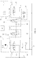
- Fig. 3 shows an exemplary hydraulic system for controlling the sawing apparatus 114 that is adapted to cross-cut tree stems.
- the hydraulic system comprises a pressure line P; a tank line T; first and second actuators 10, 18; first and second electrically operated valve arrangements 12, 20; a pilot operated third valve arrangement 26; a fourth electrically operated valve arrangement 30; and control devices.
- the pressure line P supplies fluid under pressure, namely at a first fluid pressure p1.
- the pressure line P may be in the form of a branched circuit providing flows of fluid under pressure to various parts of the hydraulic system.
- a tank line T is adapted to receive fluid flowing from the actuators.
- the pressure line P may be in fluid communication with a hydraulic pump providing the fluid under pressure.
- the tank line T may be branched and is adapted to provide low backpressure.
- the tank line T may be in fluid communication with a hydraulic reservoir to which the fluid is fed.
- the hydraulic system may further include drain lines that provide very low backpressure and convey fluid to the hydraulic reservoir.
- the first actuator 10 is a hydraulic motor to bring about a torque for driving the saw chain 118 to move at a velocity and to crosscut a tree stem.
- the first valve arrangement 12 is adapted to control a fluid flow supplied from the pressure line P to the first actuator 10.
- the fluid flows via a first line 14.
- the first valve arrangement 12 includes a selectable first state which enables the flow of fluid under pressure from the pressure line P to the first line 14.
- the first valve arrangement 12 is electrically operated in such a way that the state can be selected with an input control signal that may provide proportional control of the fluid flow.
- the velocity of the saw chain 118 is dependent on the volume flow of the fluid supplied to the first actuator 10.
- the velocity increases with the increasing volume flow.
- the volume flow via the first valve arrangement 12 depends on a pressure difference between the pressure line P and the first line 14.
- the volume flow decreases with the decreasing pressure difference.
- the fluid pressure in the pressure line P remains substantially constant during operation.
- an increasing load on the saw chain 118 may bring about an increase in the fluid pressure of the first line 14.
- the load on the saw chain 118 may vary according to the properties of the tree stem.
- the first actuator 10 provides an adequate torque for driving the saw chain 118.
- the pressure difference decreases and may have the unwanted consequence that the flow of fluid to the first actuator 10 decreases and the velocity of the saw chain 118 decreases.
- the load on the saw chain 118 decreases rapidly or disappears completely when the saw chain 118 penetrates through the tree stem and the crosscutting is fully performed. Immediately after this, the increased fluid pressure in the first line 14 and hydraulic energy accumulated in the hydraulic system may bring about a rapid, unwanted and considerable increase in the velocity of the saw chain 118.
- the first valve arrangement 12 may additionally include a selectable second state which disables the above-mentioned flow of fluid. In the second state, the first actuator 10 can be kept in a stopped state.
- the first valve arrangement 12 may include one or more directional control valves that may be pilot operated or electrically operated.
- the second actuator 18 is a hydraulic cylinder for driving the saw blade 116 to bring about a force pressing the saw chain 118 against the tree stem.
- the second valve arrangement 20 is adapted to control a fluid flow supplied from the pressure line P to the second actuator 18.
- the fluid flows via a second line 22.
- the second valve arrangement 20 includes a selectable first state which enables flow of fluid under pressure from the pressure line P to the second line 22.
- the first valve arrangement 20 is electrically operated in such a way that the state can be selected with an input control signal.
- the second valve arrangement 20 may additionally include a selectable second state which disables the above-mentioned flow of fluid, or which enables a flow of fluid under pressure from the pressure line P to the third line 24 for retracting or extending the hydraulic cylinder.
- the second valve arrangement 20 may convey fluid from the actuator 18 to the tank line T.
- the saw blade 116 is driven in an opposite, second direction away from the tree stem.
- the second valve arrangement 20 may be adapted to maintain backpressure in the actuator 18 for driving the saw blade 116 in the second direction when the flow of fluid is disabled.
- the second valve arrangement 20 may include one or more directional control valves that may be pilot operated or electrically operated.
- the third valve arrangement 26 is pilot operated by means of a pilot line 28 and is adapted to maintain a predetermined second fluid pressure p2 in the fluid flow entering the second valve arrangement 20.
- the second fluid pressure p2 is reduced in relation to the first fluid pressure p1 in such a way that the second fluid pressure p2 is dependent on third fluid pressure p3 of the pilot line 28 that is in fluid communication with the third valve arrangement 26.
- the fluid flow is adapted to enter the second valve arrangement 20 from the pressure line P via the third valve arrangement 26.
- the magnitude of the force pressing the saw blade 116 and the saw chain 118 against the tree stem is dependent on the second fluid pressure p2 present in the second actuator 18.
- the force increases with the increasing fluid pressure.
- the load on the saw chain 118 also depends on the pressing force.
- the load increases with the increasing pressing force.
- the pressing force set to a high level by means of the second fluid pressure p2 may, as described above, have the unwanted consequence that the velocity of the saw chain 118 decreases.
- the magnitude of the pressing force is set by controlling the second fluid pressure p2 by means of the third valve arrangement 26 which is controlled by the third fluid pressure p3 of the pilot line 28.
- the third valve arrangement 26 may include a function for limiting the pressure of the fluid flow.
- the third valve arrangement 26 may include a pressure limiting valve and/or a pressure reducing valve that is pilot operated and/or adjustable.
- the third valve arrangement 26 may provide proportional control in the form of a pressure control proportional valve.
- the fourth valve arrangement 30 is controlled by a first electric input control signal 32 and is adapted to be in fluid communication with the pilot line 28.
- the fourth valve arrangement 30 may be in fluid communication with the pressure line P for directing fluid to the pilot line 28.
- the fourth valve arrangement 30 is electrically operated and provides proportional control of fluid pressure.
- the fourth valve arrangement 30 is adapted to maintain the third fluid pressure p3 of the pilot line 28 at a predetermined maximum pressure level which depends on the magnitude of the first input control signal 32, being an electric signal.
- the pressing force of the second actuator 18 is indirectly controlled by means of the pressure level of the third fluid pressure p3 of the pilot line 28 and the first input control signal 32.
- the first input control signal 32 is dependent on control actions of an operator who is setting the predetermined maximum pressure level for the pilot line 28.
- the operator selects the third fluid pressure p3 by e.g. interacting with an electronic control unit 40 by means of a user interface.
- the operator sets the pressing force of saw blade 116 by means of the first input control signal 32.
- the fourth valve arrangement 30 may provide proportional control or include a directional control proportional valve and/or a restriction, or an orifice, in the pilot line 28, for inducing a pressure difference and for controlling the third fluid pressure p3.
- the electronic control unit 40 may be included in the fourth valve arrangement 30.
- the fourth valve arrangement 30 may be adapted to supply fluid from the pilot line 28 to a drain line, to maintain the third fluid pressure p3 at the predetermined maximum pressure level.
- the hydraulic system according to the solution may further comprise a sixth valve arrangement 16.
- the sixth valve arrangement 16 is adapted to maintain a predetermined substantially constant fluid flow while the first valve arrangement 12 is in the first state. The operation is carried out in such a way that the fluid flow is independent of the fluid pressure of the first line 14 and thereby any fluid pressure changes occurring in the first line 14 are compensated for. Fluid flow received by the first actuator 10 and arriving from the first line 14 is kept substantially constant. The fluid flow enters the first valve arrangement 12 from the pressure line P via the sixth valve arrangement 16.
- the sixth valve arrangement 16 may include a pressure compensating flow control valve.
- the sixth valve arrangement 16 may include a restriction 46, or an orifice, across which the fluid flows, and the fluid pressure difference across the restriction 46 is sensed for the purpose of controlling the fluid flow.
- the restriction 46 may be located upstream of the first valve arrangement 12 as shown in Fig. 3 , or within a valve or valve element of the first valve arrangement 12, or in the first line 14 between the first actuator and the first valve arrangement 12.
- the sixth valve arrangement 16 may include pilot lines for sensing the fluid pressure difference.
- the hydraulic system further comprises control devices adapted to sense the level or magnitude of the fluid pressure of the first line 14, and to sense the level or magnitude of the fluid pressure of the pressure line P, i.e. the first fluid pressure p1.
- the control devices may include valve arrangements, valves, electronic control units, control algorithms, control signals, and pressure sensors, operably connected to each other and adapted to bring about the operation as described in the examples.
- the control devices are adapted to selectively reduce the third fluid pressure p3 of the pilot line 28, the third fluid pressure p3 being additionally dependent on a first fluid pressure difference.
- one or more predetermined dependencies define the third fluid pressure p3 as a function of the first fluid pressure difference.
- the one or more predetermined dependencies may be realized in an electronic control unit, e.g. an electronic control unit 40, for controlling elements and devices of the hydraulic system.
- the first fluid pressure difference is the pressure difference between the fluid pressure of the first line 14 and the first fluid pressure p1 of the pressure line P.
- the operation to reduce the third fluid pressure p3, as described above when reducing the pressing force, is brought about in such a way that the third fluid pressure p3 decreases when the first fluid pressure difference decreases as a consequence of the fluid pressure of the first line 14 increasing.
- the operation takes place at least when the first and second valve arrangements 14, 20 are in their first states.
- the first and second actuators 10, 18 are driven to crosscut the tree stem as described above.
- An advantage of the presented solution is that the pressing force of the second actuator 18 is decreased to avoid the increased load on the saw chain 118 and the unwanted decrease in the velocity of the saw chain 118.
- An increase in the fluid pressure of the first line 14 is an indication of the decreasing velocity.
- the load on the saw chain 118 decreases and an increase in the fluid pressure of the first line 14 is avoided.
- excessive racing, i.e. sudden unintended acceleration, of the first actuator 10 and the saw chain 118 can be avoided when completing the cross-cutting.
- the control devices include a fifth valve arrangement 34 adapted to be in fluid communication with the pilot line 28.
- the fifth valve arrangement 34 may be adapted to controllably drain fluid from the pilot line 28 to decrease the third fluid pressure p3 to a level below the predetermined maximum pressure level.
- the fifth valve arrangement 34 is adapted to sense the fluid pressure of the first line 14 and the fluid pressure of the pressure line P, e.g. by means of pressure sensing lines, i.e. pilot lines.
- the fifth valve arrangement 34 may provide proportional control and is adapted to selectively reduce the third fluid pressure p3 in such a way that the third fluid pressure p3 is dependent on the first fluid pressure difference mentioned above.
- the fifth valve arrangement 34 is further adapted to selectively increase the third fluid pressure p3 in such a way that the third fluid pressure p3 is additionally dependent on the first fluid pressure difference.
- the third fluid pressure p3 increases when the first fluid pressure difference increases as a consequence of the fluid pressure of the first line 14 decreasing while the first and second valve arrangements 12, 20 are in their first states, the third fluid pressure p3 not exceeding the predetermined maximum pressure level.
- the fifth valve arrangement 34 may be pilot operated and includes either a first pilot line 36 (see Fig. 3 ) that is in fluid communication with the first line 14 for sensing the fluid pressure of the first line 14, or a second pilot line 38 that is in fluid communication with the pressure line P for sensing the fluid pressure of the pressure line P.
- the fifth valve arrangement 34 may include an electrically operated proportional control directional valve.
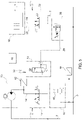
- the fifth valve arrangement 34 may comprise a first pressure sensor 42 for sensing the fluid pressure of the first line 14, or a second pressure sensor 444 (see Fig. 5 ) for sensing the fluid pressure of the pressure line P.
- the fifth valve arrangement 34 may comprise an electronic control unit, e.g. the electronic control unit 40, operably connected to the first pressure sensor 42 or the second pressure sensor 44, the electronic control unit being adapted to control the fifth valve arrangement 34 by a second input control signal 46 that is dependent on the determined fluid pressure of the pressure line P or on the determined fluid pressure of the first line 14.
- the second input control signal 46 is generated by a control algorithm running in the electronic control unit and based on one or more predetermined dependencies.
- the fifth valve arrangement 34 thus comprises one pilot line and one pressure sensor and is electronically controlled by the second input control signal 46 representing a pressure level.
- the fifth valve arrangement 34 may be internally adapted to balance forces generated by both the fluid pressure in the pilot line and the second input control signal 46 driving e.g. a solenoid. The difference between the forces represents the first fluid pressure difference.
- the fifth valve arrangement 34 may be pilot operated and includes both the first pilot line 36 for sensing the fluid pressure of the first line 14, and the second pilot line 38 for sensing the fluid pressure of the pressure line P.
- the fifth valve arrangement 34 thus comprises two pilot lines and the difference between the fluid pressures in the two pilot lines define the first fluid pressure difference.
- the fifth valve arrangement 34 may be internally adapted to balance forces generated by the fluid pressures in the pilot lines. The difference between the forces represents the first fluid pressure difference.
- the fifth valve arrangement 34 may include a pilot operated directional valve.
- the fifth valve arrangement 34 may be electrically operated and/or provide proportional control, and it may include an electrically operated proportional control directional valve.
- the fifth valve arrangement 34 comprises a first pressure sensor 42 for sensing the fluid pressure of the first line 14, and a second pressure sensor 44 (see Fig. 5 ) for sensing the fluid pressure of the pressure line P at the first fluid pressure p1.
- the fifth valve arrangement 34 may further comprise an electronic control unit, e.g. the electronic control unit 40, operably connected to the first and second sensors 42, 44, the electronic control unit being adapted to control the fifth valve arrangement 34 by the second input control signal 46.
- the second input control signal 46 is dependent on the first fluid pressure difference determined, the second input control signal 46 being generated by a control algorithm running in the electronic control unit and based on one or more predetermined dependencies.
- the control devices comprise a first pressure sensor 42 for sensing the fluid pressure of the first line 14, and a second pressure sensor 44 for sensing the fluid pressure of the pressure line P.
- the first and second pressure sensors 42, 44 may be included in the fourth valve arrangement 30.
- control devices may further comprise an electronic control unit, e.g. the electronic control unit 40, operably connected to the first and second sensors 42, 44, the electronic control unit being, as described above, adapted to control the fourth valve arrangement 30 by the first input signal 32.
- the first input signal 32 being thus additionally dependent on the determined first fluid pressure difference, the first input signal is generated by a control algorithm running in the electronic control unit and based on one or more predetermined dependencies. Control actions based on the first fluid pressure difference override control actions of an operator when adjusting the third fluid pressure p3.
- the first input control signal 32 is dependent on control actions of an operator for setting the predetermined maximum level for the third fluid pressure p3 of the pilot line 28.
- the operator sets the third fluid pressure p3 by interacting with the electronic control unit by means of a user interface.
- the operator sets the pressing force of the saw blade 116 by means of the first input control signal 32.
- the electronic control unit may be a programmable microprocessor-based device with a memory device and associated computer program code, for generating input control signals to responsively control the devices and valve arrangements.
- the control unit may have a distributed configuration with several subunits.
- each valve arrangement and control device realize the operations and functions that are described above.
- Elements needed to realize the valve arrangement, or the control device are widely known and may include one or more valves of various types, based on various operating principles, e.g. valves applying proportional or servo control, spool valves, or cartridge valves.
- the graphical symbols shown in the Figures to represent e.g. the valve arrangements do not limit the types of valves used but merely show an example how to realize the operation and functions of the hydraulic circuit.
Landscapes
- Life Sciences & Earth Sciences (AREA)
- Engineering & Computer Science (AREA)
- Mechanical Engineering (AREA)
- Forests & Forestry (AREA)
- Wood Science & Technology (AREA)
- Fluid Mechanics (AREA)
- General Engineering & Computer Science (AREA)
- Physics & Mathematics (AREA)
- Biodiversity & Conservation Biology (AREA)
- Ecology (AREA)
- Environmental Sciences (AREA)
- Chemical & Material Sciences (AREA)
- Analytical Chemistry (AREA)
- Fluid-Pressure Circuits (AREA)
- Operation Control Of Excavators (AREA)
- Sawing (AREA)
- Mechanical Treatment Of Semiconductor (AREA)
Description
- The presented solution relates to a hydraulic system for controlling a sawing apparatus adapted to cross-cut tree stems.
- The presented solution further relates to a sawing apparatus for cross-cutting tree stems and comprising a swingable saw blade around which a saw chain is adapted to travel, and a hydraulic circuit.
- The presented solution further relates to a tree stem processing tool including a sawing apparatus for cross-cutting tree stems.
- The presented solution further relates a mobile work machine.
- Mobile work machines, forestry equipment and forestry machines, e.g. harvesters and forwarders, have an articulated boom and a tree stem processing tool at the tip of the boom. The tool can be e.g. a harvester head, a felling head, or a harvesting and processing head. The tool can be applied e.g. to cut standing trees, to process felled trees or to grab objects, such as logs or tree stems, and it is operated under the control of an operator of the work machine.
- The tool may have a sawing apparatus for cross cutting a standing tree and/or a tree stem held in the tool. The sawing apparatus is e.g. a chain saw provided with a saw blade around which a saw chain travels when driven by an actuator, e.g. a hydraulic motor. The actuator is adapted to convert hydraulic pressure and fluid flow into torque and rotational speed for driving the saw chain. The sawing apparatus includes an actuator, e.g. a hydraulic cylinder, for swinging the saw blade for performing the cross-cutting. The actuator is adapted to convert hydraulic pressure and flow into force and speed of the saw blade.
- In a hydraulic system controlling the actuators, the saw chain on the saw blade is pressed against a tree stem with a force to crosscut the tree stem by means of the saw chain that is moving with a velocity. However, depending on the properties of the tree stem, the load on the motor and the saw chain pressing against the tree stem may increase and bring about a decrease in the velocity of the saw chain. The increase in the load implies an increased fluid pressure in a part of the hydraulic system and results in a decrease in the fluid flow.
- The load on the saw chain decreases rapidly or disappears completely when the saw chain penetrates through the tree stem and the crosscutting is fully performed. However, immediately after this, the increased fluid pressure and hydraulic energy accumulated in the hydraulic system bring about a rapid, unwanted increase in the velocity of the saw chain, which may be risky. A remedy is to have a pressure compensating flow control valve arrangement to keep the fluid flow supplied to the motor constant even if the load on the saw chain and the fluid pressure increases.
- Operation of the valve arrangement is not optimal in a situation in which the operation involves delays, or the valve arrangement is saturated, i.e. in a state allowing a maximum fluid flow to pass via the valve arrangement to the motor to increase the velocity. An unwanted sudden increase in the velocity of the saw chain takes place when the crosscutting is fully performed even if the valve arrangement starts to restrict the fluid flow.
- A remedy is to control the fluid flow supplied to the hydraulic cylinder that is pressing the saw blade and the saw chain against the tree stem. Such a solution is presented in
WO 2004/083653 A1 . Another known solution for controlling the sawing apparatus is disclosed inUS 2004/0020561 A1 according to the preamble of the enclosed claim 1. - The solution to be presented relates to overcoming one or more of the disadvantages noted above.
- The hydraulic system according to the invention is defined by the features of claim 1.
- The sawing apparatus according to the invention is defined by the features of claim 13. The tree stem processing tool according to the invention is defined by the features of
claim 14. The mobile work machine according to invention is defined by the features of claim 15. - According to the invention, the force with which the hydraulic cylinder presses the saw chain against the tree stem is controllably decreased to avoid the increase in the load on the saw chain and the unwanted decrease in the velocity of the saw chain. The unwanted sudden increase in the velocity of the saw chain immediately after crosscutting is avoided, or the velocity increases to an acceptable level only.
-
-
Figure 1 shows an exemplary mobile working machine according to the invention. -
Figure 2 shows an exemplary tree stem processing tool according to the invention. -
Figure 3 shows an exemplary embodiment of the hydraulic system according to the invention. -
Figure 4 shows another exemplary embodiment of the hydraulic system according to the invention. -
Figure 5 shows yet another exemplary embodiment of the hydraulic system according to the invention. - Reference will now be made to the examples which are illustrated in the accompanying drawings. Wherever possible, the same or corresponding reference numbers will be used throughout the drawings to refer to the same or corresponding parts or features.
-
Fig. 1 shows an exemplarymobile work machine 100 in which the presented solution can be applied. The mobile work machine may be a forestry machine, for example a harvester for harvesting and processing timber or tree stems, as shown inFig. 1 , or a forwarder for transferring timber or tree stems. Themobile work machine 100 may be an excavator-based machine. - The mobile work machine 100 (also referred to herein as a machine, a mobile working machine, and a vehicle) comprises a
frame 102 and an articulated boom 104 (also referred to herein as a boom) on theframe 102. Themachine 100 may further comprise acabin 104 with an operator's station on theframe 102. - The
frame 102 may be articulated and have two or more frame sections connected one after the other by means of a controlled joint. Theframe 102 may be wheeled and supported by several wheels. Alternatively, theframe 102 may have an endless track arrangement, i.e. a caterpillar track, for supporting theframe 102 and for driving themachine 100. - The
boom 104 may be mounted on theframe 102 or aslewing apparatus 106 connected to theframe 102 for changing the orientation of theboom 104, or theframe 102 rotates in relation to the endless track arrangement. Theboom 104 can be rotated about a rotation axis that is substantially vertical. Theboom 104 may have two or more boom sections connected one after the other by means of joint arrangements controlled by means of one or several actuators, e.g. hydraulic cylinders. -
Fig. 2 shows an exemplary tree stem processing tool 108 (also referred to herein as a tool) that may be connected to theboom 104. Preferably, thetool 108 is connected to the end of theboom 104. - The
tool 108 may be rotatably connected to theboom 108 by means of anactuator 110, e.g. a rotary actuator or a rotator. By means of theactuator 110, thetool 104 suspended from theactuator 110 can be controllably rotated about a rotation axis that is oriented substantially vertically. - The
tool 108 may be a harvester head, a felling head, a harvesting and processing head, or a harvester head suitable for use as a log grapple. According to the example ofFig. 1 , thetool 108 is a harvester head for harvesting and processing timber by first grabbing and felling a standing tree and then debranching and cross cutting the tree stem. - The
tool 108 may include a frame includingtilting devices 122 enabling tilting of a housing of thetool 108. Thetool 108 may have two ormore arms 120 pivotally connected to the housing of thetool 108 for grabbing a standing tree, a log, or a tree stem e.g. from two opposite sides. Thearms 120 may be additionally constructed as blades for debranching a tree stem held in thetool 108. - The
tool 108 may comprise afeeding device 112 for transferring a tree stem through thetool 108 while being held in thetool 108. The tree stem is transferred in its longitudinal direction. Thefeeding device 112 may include one or more feed wheels that contact the tree stem and are adapted to rotate for transferring the tree stem. The tree stem is transferred for simultaneously debranching the tree stem by means of blades and/or for moving the tree stem to a position in which it is crosscut. - The
tool 108 has asawing apparatus 114 for cross cutting a standing tree and/or a tree stem held in thetool 108. Thesawing apparatus 114 is e.g. a chain saw provided with aswingable saw blade 116 around which asaw chain 118 travels when driven by an actuator, e.g. a rotary actuator or a motor. The motor may be a hydraulic motor adapted to convert hydraulic pressure and flow into torque and rotational speed for driving thesaw chain 118. Thesawing apparatus 114 includes an actuator for swinging thesaw blade 116 for performing the cross-cutting, the actuator being adapted to convert hydraulic pressure and flow into force and speed of thesaw blade 116. -
Fig. 3 shows an exemplary hydraulic system for controlling thesawing apparatus 114 that is adapted to cross-cut tree stems. - The hydraulic system according to the solution comprises a pressure line P; a tank line T; first and
second actuators valve arrangements third valve arrangement 26; a fourth electrically operatedvalve arrangement 30; and control devices. - The pressure line P supplies fluid under pressure, namely at a first fluid pressure p1. The pressure line P may be in the form of a branched circuit providing flows of fluid under pressure to various parts of the hydraulic system. A tank line T is adapted to receive fluid flowing from the actuators. The pressure line P may be in fluid communication with a hydraulic pump providing the fluid under pressure. The tank line T may be branched and is adapted to provide low backpressure. The tank line T may be in fluid communication with a hydraulic reservoir to which the fluid is fed. The hydraulic system may further include drain lines that provide very low backpressure and convey fluid to the hydraulic reservoir.
- The
first actuator 10 is a hydraulic motor to bring about a torque for driving thesaw chain 118 to move at a velocity and to crosscut a tree stem. - The
first valve arrangement 12 is adapted to control a fluid flow supplied from the pressure line P to thefirst actuator 10. The fluid flows via afirst line 14. For driving thefirst actuator 10, thefirst valve arrangement 12 includes a selectable first state which enables the flow of fluid under pressure from the pressure line P to thefirst line 14. Thefirst valve arrangement 12 is electrically operated in such a way that the state can be selected with an input control signal that may provide proportional control of the fluid flow. - The velocity of the
saw chain 118 is dependent on the volume flow of the fluid supplied to thefirst actuator 10. The velocity increases with the increasing volume flow. The volume flow via thefirst valve arrangement 12 depends on a pressure difference between the pressure line P and thefirst line 14. The volume flow decreases with the decreasing pressure difference. The fluid pressure in the pressure line P remains substantially constant during operation. - Therefore, an increasing load on the
saw chain 118 may bring about an increase in the fluid pressure of thefirst line 14. The load on thesaw chain 118 may vary according to the properties of the tree stem. Thefirst actuator 10 provides an adequate torque for driving thesaw chain 118. Thus, the pressure difference decreases and may have the unwanted consequence that the flow of fluid to thefirst actuator 10 decreases and the velocity of thesaw chain 118 decreases. - The load on the
saw chain 118 decreases rapidly or disappears completely when thesaw chain 118 penetrates through the tree stem and the crosscutting is fully performed. Immediately after this, the increased fluid pressure in thefirst line 14 and hydraulic energy accumulated in the hydraulic system may bring about a rapid, unwanted and considerable increase in the velocity of thesaw chain 118. - The
first valve arrangement 12 may additionally include a selectable second state which disables the above-mentioned flow of fluid. In the second state, thefirst actuator 10 can be kept in a stopped state. - The
first valve arrangement 12 may include one or more directional control valves that may be pilot operated or electrically operated. - The
second actuator 18 is a hydraulic cylinder for driving thesaw blade 116 to bring about a force pressing thesaw chain 118 against the tree stem. - The
second valve arrangement 20 is adapted to control a fluid flow supplied from the pressure line P to thesecond actuator 18. The fluid flows via asecond line 22. For driving thesecond actuator 18 in a first direction, e.g. for extending or retracting the hydraulic cylinder, thesecond valve arrangement 20 includes a selectable first state which enables flow of fluid under pressure from the pressure line P to thesecond line 22. Thefirst valve arrangement 20 is electrically operated in such a way that the state can be selected with an input control signal. - The
second valve arrangement 20 may additionally include a selectable second state which disables the above-mentioned flow of fluid, or which enables a flow of fluid under pressure from the pressure line P to thethird line 24 for retracting or extending the hydraulic cylinder. In the first and second states, thesecond valve arrangement 20 may convey fluid from theactuator 18 to the tank line T. Thus, thesaw blade 116 is driven in an opposite, second direction away from the tree stem. - Additionally, or alternatively, the
second valve arrangement 20 may be adapted to maintain backpressure in theactuator 18 for driving thesaw blade 116 in the second direction when the flow of fluid is disabled. - The
second valve arrangement 20 may include one or more directional control valves that may be pilot operated or electrically operated. - The
third valve arrangement 26 is pilot operated by means of apilot line 28 and is adapted to maintain a predetermined second fluid pressure p2 in the fluid flow entering thesecond valve arrangement 20. The second fluid pressure p2 is reduced in relation to the first fluid pressure p1 in such a way that the second fluid pressure p2 is dependent on third fluid pressure p3 of thepilot line 28 that is in fluid communication with thethird valve arrangement 26. The fluid flow is adapted to enter thesecond valve arrangement 20 from the pressure line P via thethird valve arrangement 26. - The magnitude of the force pressing the
saw blade 116 and thesaw chain 118 against the tree stem is dependent on the second fluid pressure p2 present in thesecond actuator 18. The force increases with the increasing fluid pressure. - The load on the
saw chain 118 also depends on the pressing force. The load increases with the increasing pressing force. Thus, the pressing force set to a high level by means of the second fluid pressure p2 may, as described above, have the unwanted consequence that the velocity of thesaw chain 118 decreases. The magnitude of the pressing force is set by controlling the second fluid pressure p2 by means of thethird valve arrangement 26 which is controlled by the third fluid pressure p3 of thepilot line 28. - The
third valve arrangement 26 may include a function for limiting the pressure of the fluid flow. Thethird valve arrangement 26 may include a pressure limiting valve and/or a pressure reducing valve that is pilot operated and/or adjustable. Thethird valve arrangement 26 may provide proportional control in the form of a pressure control proportional valve. - The
fourth valve arrangement 30 is controlled by a first electricinput control signal 32 and is adapted to be in fluid communication with thepilot line 28. Thefourth valve arrangement 30 may be in fluid communication with the pressure line P for directing fluid to thepilot line 28. Thefourth valve arrangement 30 is electrically operated and provides proportional control of fluid pressure. Thus, thefourth valve arrangement 30 is adapted to maintain the third fluid pressure p3 of thepilot line 28 at a predetermined maximum pressure level which depends on the magnitude of the firstinput control signal 32, being an electric signal. - Thus, the pressing force of the
second actuator 18 is indirectly controlled by means of the pressure level of the third fluid pressure p3 of thepilot line 28 and the firstinput control signal 32. - The first
input control signal 32 is dependent on control actions of an operator who is setting the predetermined maximum pressure level for thepilot line 28. The operator selects the third fluid pressure p3 by e.g. interacting with anelectronic control unit 40 by means of a user interface. Thus, the operator sets the pressing force ofsaw blade 116 by means of the firstinput control signal 32. - The
fourth valve arrangement 30 may provide proportional control or include a directional control proportional valve and/or a restriction, or an orifice, in thepilot line 28, for inducing a pressure difference and for controlling the third fluid pressure p3. Theelectronic control unit 40 may be included in thefourth valve arrangement 30. - The
fourth valve arrangement 30 may be adapted to supply fluid from thepilot line 28 to a drain line, to maintain the third fluid pressure p3 at the predetermined maximum pressure level. - The hydraulic system according to the solution may further comprise a
sixth valve arrangement 16. - The
sixth valve arrangement 16 is adapted to maintain a predetermined substantially constant fluid flow while thefirst valve arrangement 12 is in the first state. The operation is carried out in such a way that the fluid flow is independent of the fluid pressure of thefirst line 14 and thereby any fluid pressure changes occurring in thefirst line 14 are compensated for. Fluid flow received by thefirst actuator 10 and arriving from thefirst line 14 is kept substantially constant. The fluid flow enters thefirst valve arrangement 12 from the pressure line P via thesixth valve arrangement 16. - The
sixth valve arrangement 16 may include a pressure compensating flow control valve. Thesixth valve arrangement 16 may include arestriction 46, or an orifice, across which the fluid flows, and the fluid pressure difference across therestriction 46 is sensed for the purpose of controlling the fluid flow. - The
restriction 46 may be located upstream of thefirst valve arrangement 12 as shown inFig. 3 , or within a valve or valve element of thefirst valve arrangement 12, or in thefirst line 14 between the first actuator and thefirst valve arrangement 12. Thesixth valve arrangement 16 may include pilot lines for sensing the fluid pressure difference. - According to the invention, the hydraulic system further comprises control devices adapted to sense the level or magnitude of the fluid pressure of the
first line 14, and to sense the level or magnitude of the fluid pressure of the pressure line P, i.e. the first fluid pressure p1. The control devices may include valve arrangements, valves, electronic control units, control algorithms, control signals, and pressure sensors, operably connected to each other and adapted to bring about the operation as described in the examples. - The control devices are adapted to selectively reduce the third fluid pressure p3 of the
pilot line 28, the third fluid pressure p3 being additionally dependent on a first fluid pressure difference. For example, one or more predetermined dependencies define the third fluid pressure p3 as a function of the first fluid pressure difference. The one or more predetermined dependencies may be realized in an electronic control unit, e.g. anelectronic control unit 40, for controlling elements and devices of the hydraulic system. - The first fluid pressure difference is the pressure difference between the fluid pressure of the
first line 14 and the first fluid pressure p1 of the pressure line P. The operation to reduce the third fluid pressure p3, as described above when reducing the pressing force, is brought about in such a way that the third fluid pressure p3 decreases when the first fluid pressure difference decreases as a consequence of the fluid pressure of thefirst line 14 increasing. The operation takes place at least when the first andsecond valve arrangements - During the operation, the first and
second actuators - An advantage of the presented solution is that the pressing force of the
second actuator 18 is decreased to avoid the increased load on thesaw chain 118 and the unwanted decrease in the velocity of thesaw chain 118. An increase in the fluid pressure of thefirst line 14 is an indication of the decreasing velocity. - Thus, the load on the
saw chain 118 decreases and an increase in the fluid pressure of thefirst line 14 is avoided. Thus, when cross-cutting the tree stem, excessive racing, i.e. sudden unintended acceleration, of thefirst actuator 10 and thesaw chain 118 can be avoided when completing the cross-cutting. - In the following, examples of the control devices are presented.
- As shown in
Figs. 3 and4 , according to a first example of the solution, the control devices include afifth valve arrangement 34 adapted to be in fluid communication with thepilot line 28. Thefifth valve arrangement 34 may be adapted to controllably drain fluid from thepilot line 28 to decrease the third fluid pressure p3 to a level below the predetermined maximum pressure level. - To accomplish this, the
fifth valve arrangement 34 is adapted to sense the fluid pressure of thefirst line 14 and the fluid pressure of the pressure line P, e.g. by means of pressure sensing lines, i.e. pilot lines. Thefifth valve arrangement 34 may provide proportional control and is adapted to selectively reduce the third fluid pressure p3 in such a way that the third fluid pressure p3 is dependent on the first fluid pressure difference mentioned above. - According to an example, the
fifth valve arrangement 34 is further adapted to selectively increase the third fluid pressure p3 in such a way that the third fluid pressure p3 is additionally dependent on the first fluid pressure difference. Thereby, the third fluid pressure p3 increases when the first fluid pressure difference increases as a consequence of the fluid pressure of thefirst line 14 decreasing while the first andsecond valve arrangements - As shown in
Fig. 4 , according to a first option of the first example, thefifth valve arrangement 34 may be pilot operated and includes either a first pilot line 36 (seeFig. 3 ) that is in fluid communication with thefirst line 14 for sensing the fluid pressure of thefirst line 14, or asecond pilot line 38 that is in fluid communication with the pressure line P for sensing the fluid pressure of the pressure line P. - Additionally, the
fifth valve arrangement 34 may include an electrically operated proportional control directional valve. Thefifth valve arrangement 34 may comprise afirst pressure sensor 42 for sensing the fluid pressure of thefirst line 14, or a second pressure sensor 444 (seeFig. 5 ) for sensing the fluid pressure of the pressure line P. - In this option, the
fifth valve arrangement 34 may comprise an electronic control unit, e.g. theelectronic control unit 40, operably connected to thefirst pressure sensor 42 or thesecond pressure sensor 44, the electronic control unit being adapted to control thefifth valve arrangement 34 by a secondinput control signal 46 that is dependent on the determined fluid pressure of the pressure line P or on the determined fluid pressure of thefirst line 14. The secondinput control signal 46 is generated by a control algorithm running in the electronic control unit and based on one or more predetermined dependencies. - The
fifth valve arrangement 34 thus comprises one pilot line and one pressure sensor and is electronically controlled by the secondinput control signal 46 representing a pressure level. Thefifth valve arrangement 34 may be internally adapted to balance forces generated by both the fluid pressure in the pilot line and the secondinput control signal 46 driving e.g. a solenoid. The difference between the forces represents the first fluid pressure difference. - As shown in
Fig. 3 , according to a second option of the first example, thefifth valve arrangement 34 may be pilot operated and includes both thefirst pilot line 36 for sensing the fluid pressure of thefirst line 14, and thesecond pilot line 38 for sensing the fluid pressure of the pressure line P. - The
fifth valve arrangement 34 thus comprises two pilot lines and the difference between the fluid pressures in the two pilot lines define the first fluid pressure difference. Thefifth valve arrangement 34 may be internally adapted to balance forces generated by the fluid pressures in the pilot lines. The difference between the forces represents the first fluid pressure difference. Thefifth valve arrangement 34 may include a pilot operated directional valve. - Based on the second option shown in
Fig 4 , according to a third option of the first example, thefifth valve arrangement 34 may be electrically operated and/or provide proportional control, and it may include an electrically operated proportional control directional valve. - In this option, see
Fig. 4 , thefifth valve arrangement 34 comprises afirst pressure sensor 42 for sensing the fluid pressure of thefirst line 14, and a second pressure sensor 44 (seeFig. 5 ) for sensing the fluid pressure of the pressure line P at the first fluid pressure p1. - The
fifth valve arrangement 34 may further comprise an electronic control unit, e.g. theelectronic control unit 40, operably connected to the first andsecond sensors fifth valve arrangement 34 by the secondinput control signal 46. The secondinput control signal 46 is dependent on the first fluid pressure difference determined, the secondinput control signal 46 being generated by a control algorithm running in the electronic control unit and based on one or more predetermined dependencies. - As shown in
Fig. 5 , according to a second example of the solution, the control devices comprise afirst pressure sensor 42 for sensing the fluid pressure of thefirst line 14, and asecond pressure sensor 44 for sensing the fluid pressure of the pressure line P. The first andsecond pressure sensors fourth valve arrangement 30. - In the second example, the control devices, or the
fourth valve arrangement 30, may further comprise an electronic control unit, e.g. theelectronic control unit 40, operably connected to the first andsecond sensors fourth valve arrangement 30 by thefirst input signal 32. Thefirst input signal 32 being thus additionally dependent on the determined first fluid pressure difference, the first input signal is generated by a control algorithm running in the electronic control unit and based on one or more predetermined dependencies. Control actions based on the first fluid pressure difference override control actions of an operator when adjusting the third fluid pressure p3. - Additionally, the first
input control signal 32 is dependent on control actions of an operator for setting the predetermined maximum level for the third fluid pressure p3 of thepilot line 28. The operator sets the third fluid pressure p3 by interacting with the electronic control unit by means of a user interface. Thus, the operator sets the pressing force of thesaw blade 116 by means of the firstinput control signal 32. - The electronic control unit may be a programmable microprocessor-based device with a memory device and associated computer program code, for generating input control signals to responsively control the devices and valve arrangements. The control unit may have a distributed configuration with several subunits.
- Other components necessary for the basic functioning of the presented hydraulic circuit and for controlling flows of fluid in the presented system may be added to the solution presented in the Figures.
- Furthermore, each valve arrangement and control device realize the operations and functions that are described above. Elements needed to realize the valve arrangement, or the control device, are widely known and may include one or more valves of various types, based on various operating principles, e.g. valves applying proportional or servo control, spool valves, or cartridge valves. The graphical symbols shown in the Figures to represent e.g. the valve arrangements do not limit the types of valves used but merely show an example how to realize the operation and functions of the hydraulic circuit.
- The verbs "to comprise" and "to include" are used in this document as open limitations that neither exclude nor require the existence of features that are not cited. Furthermore, it is to be understood that the use of "a" or "an", i.e. a singular form, throughout this document does not exclude a plurality, unless where specifically mentioned.
- In the description, numerous specific details are set forth in order to provide a thorough understanding of the present solution. It is to be understood that the examples of the solution disclosed are not limited to the structures disclosed herein, but are extended to equivalents thereof as would be recognized by those skilled in the relevant art.
- The solution is not limited solely to the above-presented embodiments, but it can be modified within the scope of the appended claims.
Claims (15)
- A hydraulic system for controlling a sawing apparatus adapted to cross-cut tree stems, the hydraulic system comprising:- a pressure line (P) adapted to supply fluid under pressure, namely at a first fluid pressure p1;- a tank line (T) adapted to receive fluid flowing from actuators;- a first actuator (10) being a hydraulic motor to bring about torque for driving the sawing apparatus to move at a velocity and to crosscut a tree stem;- a first electrically operated valve arrangement (12) adapted to control a fluid flow supplied from the pressure line (P) to the first actuator (10) via a first line (14), wherein the first valve arrangement (12) includes:- a selectable first state to enable a flow of fluid under pressure from the pressure line (P) to the first line (14) to drive the first actuator (10);- a second actuator (18) being a hydraulic cylinder for driving the sawing apparatus to bring about a force pressing the sawing apparatus against the tree stem,- a second electrically operated valve arrangement (20) adapted to control a fluid flow supplied from the pressure line (P) to the second actuator (18) through a second line (22), wherein the second valve arrangement (20) includes:- a selectable first state to enable a flow of fluid under pressure from the pressure line (P) to the second line (22) to drive the second actuator (18);- a third valve arrangement (26) adapted to maintain a predetermined second fluid pressure p2 in the fluid flow entering the second valve arrangement (20), the second fluid pressure p2 being reduced in relation to the first fluid pressure p1,- wherein the fluid flow is adapted to enter the second valve arrangement (20) from the pressure line (P) through the third valve arrangement (26);- control devices which are adapted to sense the fluid pressure of the first line (14);characterized by:- the sawing apparatus includes a swingable saw blade around which a saw chain is adapted to travel, wherein the first actuator (10) is adapted to drive the saw chain and the second actuator (18) is adapted to drive the saw blade to press the saw chain against the tree stem;- the third valve arrangement (26) is pilot operated and the second fluid pressure p2 is further dependent on a third fluid pressure p3 of a pilot line (28) that is in fluid communication with the third valve arrangement (26);- a fourth electrically operated valve arrangement (30) controlled by a first electric input control signal (32) and adapted to be in fluid communication with the pilot line (28),the hydraulic system further comprises:- wherein the fourth valve arrangement (30) is adapted to maintain the third fluid pressure p3 of the pilot line (28) at a predetermined maximum pressure level dependent on the magnitude of the first input control signal (32); and- control devices which are adapted to sense the fluid pressure of the pressure line (P), namely the first fluid pressure p1,- wherein the control devices are adapted to selectively reduce the third fluid pressure p3 of the pilot line (28), the third fluid pressure p3 being additionally dependent on a first fluid pressure difference between the fluid pressure of the first line (14) and the first fluid pressure p1 of the pressure line (P) in such a way that the third fluid pressure p3decreases when the first fluid pressure difference decreases as a consequence of the fluid pressure of the first line (14) increasing while the first and second valve arrangements (12, 20) are in their first states.
- The hydraulic system according to claim 1, wherein the control devices include:- a fifth control valve arrangement (34) adapted to be in fluid communication with the pilot line (28), to sense the fluid pressure of the first line (14), and to sense the fluid pressure of the pressure line (P),- wherein the fifth valve arrangement (34) is adapted to selectively reduce the third fluid pressure p3 of the pilot line (28) in such a way that the third fluid pressure p3 is dependent on the first fluid pressure difference.
- The hydraulic system according to claim 2, wherein the fifth valve arrangement (34) is further adapted to selectively increase the third fluid pressure p3 of the pilot line (28) in such a way that the third fluid pressure p3 is additionally dependent on the first fluid pressure difference, the third fluid pressure p3 not exceeding the predetermined maximum pressure level.
- The hydraulic system according to claim 2 or 3, wherein the fifth valve arrangement (34) is pilot operated and comprises:- (i) a first pilot line (36) in fluid communication with the first line (14) for sensing the fluid pressure of the first line (14), or- (ii) a second pilot line (38) in fluid communication with the pressure line (P) for sensing the fluid pressure of the pressure line (P), namely the first fluid pressure p1.
- The hydraulic system according to any one of claims 2 to 4, wherein the fifth valve arrangement (34) further comprises:- (i) a first pressure sensor (42) for sensing the fluid pressure of the first line (14), or- (ii) a second pressure sensor (44) for sensing the fluid pressure of the pressure line (P), and- an electronic control unit (40) operably connected to the first and second sensors (42, 44) and being adapted to control the fifth valve arrangement (34) by a second input control signal (46) which is dependent on (i) the fluid pressure of the pressure line P determined or on (ii) the fluid pressure of the first line (14) determined, the second input control signal (46) being generated by a control algorithm running in the electronic control unit (40).
- The hydraulic system according to claim 2 or 3, wherein the fifth valve arrangement (34) is pilot operated and comprises:- a first pilot line (36) in fluid communication with the first line (14) for sensing the fluid pressure of the first line (14), and- a second pilot line (38) in fluid communication with the pressure line (P) for sensing the fluid pressure of the pressure line (P).
- The hydraulic system according to any one of claims 2, 3 or 6, wherein the fifth valve arrangement (34) comprises:- a first pressure sensor (42) for sensing the fluid pressure of the first line (14), and- a second pressure sensor (44) for sensing the fluid pressure of the pressure line (P),- an electronic control unit (40) operably connected to the first and second pressure sensors (42, 44) and being adapted to control the fifth valve arrangement (34) by a second input control signal (46) which is dependent on the determined first fluid pressure difference, the second input control signal (46) being generated by a control algorithm running in the electronic control unit (40).
- The hydraulic system according to any one of claims 2 to 7, wherein the fifth valve arrangement (34) includes an electrically operated directional valve or a pilot operated directional valve.
- The hydraulic system according to claim 1, wherein the control devices include:- a first pressure sensor (42) for sensing the fluid pressure of the first line (14),- a second pressure sensor (44) for sensing the fluid pressure of the pressure line (P), and- an electronic control unit (40) operably connected to the first and second sensors (42, 44) and being adapted to control the fourth valve arrangement (30) by the first input control signal (32) which is additionally dependent on the determined first fluid pressure difference, the first input control signal (32) being generated by a control algorithm running in the electronic control unit (40).
- The hydraulic system according to any one of claims 1 to 9, wherein the fourth valve arrangement (30) includes an electrically operated proportional control directional valve adapted to be controlled by the first input control signal (32).
- The hydraulic system according to any one of claims 1 to 10, wherein the hydraulic system further comprises:- a sixth valve arrangement (16) adapted to maintain a predetermined substantially constant fluid flow in the first state of the first valve arrangement (12) in such a way that the fluid flow is independent of the fluid pressure of the first line (14) whereby fluid pressure changes occurring in the first line (14) are compensated for,- wherein the fluid flow is adapted to enter the first valve arrangement (12) from the pressure line (P) via the sixth valve arrangement (16).
- The hydraulic system according to any one of claims 1 to 11, wherein the hydraulic system further comprises an electronic control unit (40) operably connected to the fourth valve arrangement (30), for transmitting the first input control signal (32) generated by a control algorithm running in the electronic control unit (40) under control of an operator.
- A sawing apparatus (114) for cross-cutting tree stems, comprising a swingable saw blade (116) around which a saw chain (118) is adapted to travel and the hydraulic system according to any one of claims 1 to 12.
- A tree stem processing tool (108) including a sawing apparatus (114) for cross-cutting tree stems, the sawing apparatus (114) comprising a swingable saw blade (116) around which a saw chain (118) is adapted to travel, and the hydraulic system according to any one of claims 1 to 12.
- A mobile work machine (100) including a frame (102), an articulated boom (104) on the frame, and a tree stem processing tool (108) connected to the articulated boom, the tree stem processing tool (108) including a sawing apparatus (114) for cross-cutting tree stems, the sawing apparatus (114) comprising a swingable saw blade (116) around which a saw chain (118) is adapted to travel, and the hydraulic system according to any one of claims 1 to 12.
Applications Claiming Priority (1)
| Application Number | Priority Date | Filing Date | Title |
|---|---|---|---|
| FI20195915A FI129652B (en) | 2019-10-24 | 2019-10-24 | Hydraulic system for controlling a sawing apparatus |
Publications (2)
| Publication Number | Publication Date |
|---|---|
| EP3812112A1 EP3812112A1 (en) | 2021-04-28 |
| EP3812112B1 true EP3812112B1 (en) | 2023-01-04 |
Family
ID=72826822
Family Applications (1)
| Application Number | Title | Priority Date | Filing Date |
|---|---|---|---|
| EP20397511.5A Active EP3812112B1 (en) | 2019-10-24 | 2020-09-18 | Hydraulic system for controlling a sawing apparatus |
Country Status (3)
| Country | Link |
|---|---|
| EP (1) | EP3812112B1 (en) |
| CA (1) | CA3093892A1 (en) |
| FI (2) | FI129652B (en) |
Families Citing this family (4)
| Publication number | Priority date | Publication date | Assignee | Title |
|---|---|---|---|---|
| EP3984354B1 (en) * | 2020-10-14 | 2023-07-26 | Dipperfox OÜ | Stump crusher |
| FI130631B (en) * | 2021-10-21 | 2023-12-19 | Ponsse Oyj | Control circuit for a harvester assembly |
| CN115750485A (en) * | 2022-09-26 | 2023-03-07 | 中国国际海运集装箱(集团)股份有限公司 | Hydraulic system of bamboo cutting machine head and control method |
| SE548185C2 (en) * | 2024-09-12 | 2026-04-15 | Komatsu Forest Ab | Cut-to-length logging harvester vehicle and harvester head, and operating method for a cut-to-length logging harvester vehicle |
Family Cites Families (4)
| Publication number | Priority date | Publication date | Assignee | Title |
|---|---|---|---|---|
| SE388752B (en) * | 1975-03-06 | 1976-10-18 | Volvo Bm | DEVICE FOR CUTTING TREES OF TREES |
| US4368763A (en) * | 1981-01-12 | 1983-01-18 | Eaton George H | Apparatus for controlled cutting down of trees |
| US6986368B2 (en) * | 2002-08-01 | 2006-01-17 | Risley Enterprises Ltd. | Hydraulic control system for tree cutting saw |
| SE526759C2 (en) | 2003-03-21 | 2005-11-01 | Parker Hannifin Ab | Device for controlling hydraulic drive units |
-
2019
- 2019-10-24 FI FI20195915A patent/FI129652B/en active IP Right Grant
-
2020
- 2020-09-18 EP EP20397511.5A patent/EP3812112B1/en active Active
- 2020-09-18 FI FIEP20397511.5T patent/FI3812112T3/en active
- 2020-09-22 CA CA3093892A patent/CA3093892A1/en active Pending
Also Published As
| Publication number | Publication date |
|---|---|
| CA3093892A1 (en) | 2021-04-24 |
| FI129652B (en) | 2022-06-15 |
| EP3812112A1 (en) | 2021-04-28 |
| FI3812112T3 (en) | 2023-03-22 |
| FI20195915A1 (en) | 2021-04-25 |
Similar Documents
| Publication | Publication Date | Title |
|---|---|---|
| EP3812112B1 (en) | Hydraulic system for controlling a sawing apparatus | |
| US8430621B2 (en) | Control of a boom construction and a tool articulated thereto | |
| US6267163B1 (en) | Method and apparatus for operating a hydraulic drive system of a feller-buncher | |
| US9545062B2 (en) | Integrated hydraulic system for harvester | |
| US7874327B2 (en) | Tree feeding control for a tree handling device | |
| CA1061680A (en) | Hydraulic circuit for tree harvesting implement | |
| CA2422978C (en) | Method of controlling press power in a limbing knife assembly in a single-grip harvester head | |
| US20210400888A1 (en) | Tree Felling Head Control System and Method | |
| US6186198B1 (en) | Method and apparatus for distributing hydraulic power in a feller-buncher | |
| FI91587C (en) | Systems for controlling press means of a tree harvester, in particular of a gripper harvester | |
| JP7224055B2 (en) | Hydraulic system for multi-process machines and multi-process machines using this hydraulic system | |
| EP3769611B1 (en) | A timber working device | |
| WO2026057646A1 (en) | Cut-to-length logging harvester vehicle and harvester head, and operating method for a cut-to-length logging harvester vehicle | |
| JP4614560B2 (en) | Bark peeling hydraulic circuit | |
| WO2024141708A1 (en) | A method for processing wood and a control system for controlling the operation of the harvester head of a forest work machine | |
| FI20246113A1 (en) | HARVESTER VEHICLE AND HARVESTER HEAD ACCORDING TO THE GOODS TYPE METHOD AND DRIVE METHOD FOR A FORGER MACHINE ACCORDING TO THE GOODS TYPE METHOD | |
| JP2015167509A (en) | Forestry machine | |
| WO2000033641A1 (en) | Method and apparatus for distributing hydraulic power in a feller-buncher | |
| FI91703C (en) | Control and drive system for a cutting saw at the end of a swing bar of a tree treatment machine | |
| JP2023064319A (en) | tree processor | |
| FI12941Y1 (en) | Arrangement to control a delimbing and barking blade of a trunk processing tool | |
| WO2008143644A1 (en) | Debarker head |
Legal Events
| Date | Code | Title | Description |
|---|---|---|---|
| PUAI | Public reference made under article 153(3) epc to a published international application that has entered the european phase |
Free format text: ORIGINAL CODE: 0009012 |
|
| STAA | Information on the status of an ep patent application or granted ep patent |
Free format text: STATUS: THE APPLICATION HAS BEEN PUBLISHED |
|
| AK | Designated contracting states |
Kind code of ref document: A1 Designated state(s): AL AT BE BG CH CY CZ DE DK EE ES FI FR GB GR HR HU IE IS IT LI LT LU LV MC MK MT NL NO PL PT RO RS SE SI SK SM TR |
|
| AX | Request for extension of the european patent |
Extension state: BA ME |
|
| STAA | Information on the status of an ep patent application or granted ep patent |
Free format text: STATUS: REQUEST FOR EXAMINATION WAS MADE |
|
| 17P | Request for examination filed |
Effective date: 20211006 |
|
| RBV | Designated contracting states (corrected) |
Designated state(s): AL AT BE BG CH CY CZ DE DK EE ES FI FR GB GR HR HU IE IS IT LI LT LU LV MC MK MT NL NO PL PT RO RS SE SI SK SM TR |
|
| GRAP | Despatch of communication of intention to grant a patent |
Free format text: ORIGINAL CODE: EPIDOSNIGR1 |
|
| STAA | Information on the status of an ep patent application or granted ep patent |
Free format text: STATUS: GRANT OF PATENT IS INTENDED |
|
| INTG | Intention to grant announced |
Effective date: 20220921 |
|
| GRAS | Grant fee paid |
Free format text: ORIGINAL CODE: EPIDOSNIGR3 |
|
| GRAA | (expected) grant |
Free format text: ORIGINAL CODE: 0009210 |
|
| STAA | Information on the status of an ep patent application or granted ep patent |
Free format text: STATUS: THE PATENT HAS BEEN GRANTED |
|
| AK | Designated contracting states |
Kind code of ref document: B1 Designated state(s): AL AT BE BG CH CY CZ DE DK EE ES FI FR GB GR HR HU IE IS IT LI LT LU LV MC MK MT NL NO PL PT RO RS SE SI SK SM TR |
|
| REG | Reference to a national code |
Ref country code: GB Ref legal event code: FG4D |
|
| REG | Reference to a national code |
Ref country code: DE Ref legal event code: R096 Ref document number: 602020007362 Country of ref document: DE |
|
| REG | Reference to a national code |
Ref country code: CH Ref legal event code: EP |
|
| REG | Reference to a national code |
Ref country code: AT Ref legal event code: REF Ref document number: 1541610 Country of ref document: AT Kind code of ref document: T Effective date: 20230115 |
|
| REG | Reference to a national code |
Ref country code: IE Ref legal event code: FG4D |
|
| REG | Reference to a national code |
Ref country code: SE Ref legal event code: TRGR |
|
| REG | Reference to a national code |
Ref country code: LT Ref legal event code: MG9D |
|
| REG | Reference to a national code |
Ref country code: NL Ref legal event code: MP Effective date: 20230104 |
|
| REG | Reference to a national code |
Ref country code: AT Ref legal event code: MK05 Ref document number: 1541610 Country of ref document: AT Kind code of ref document: T Effective date: 20230104 |
|
| PG25 | Lapsed in a contracting state [announced via postgrant information from national office to epo] |
Ref country code: NL Free format text: LAPSE BECAUSE OF FAILURE TO SUBMIT A TRANSLATION OF THE DESCRIPTION OR TO PAY THE FEE WITHIN THE PRESCRIBED TIME-LIMIT Effective date: 20230104 |
|
| PG25 | Lapsed in a contracting state [announced via postgrant information from national office to epo] |
Ref country code: RS Free format text: LAPSE BECAUSE OF FAILURE TO SUBMIT A TRANSLATION OF THE DESCRIPTION OR TO PAY THE FEE WITHIN THE PRESCRIBED TIME-LIMIT Effective date: 20230104 Ref country code: PT Free format text: LAPSE BECAUSE OF FAILURE TO SUBMIT A TRANSLATION OF THE DESCRIPTION OR TO PAY THE FEE WITHIN THE PRESCRIBED TIME-LIMIT Effective date: 20230504 Ref country code: NO Free format text: LAPSE BECAUSE OF FAILURE TO SUBMIT A TRANSLATION OF THE DESCRIPTION OR TO PAY THE FEE WITHIN THE PRESCRIBED TIME-LIMIT Effective date: 20230404 Ref country code: LV Free format text: LAPSE BECAUSE OF FAILURE TO SUBMIT A TRANSLATION OF THE DESCRIPTION OR TO PAY THE FEE WITHIN THE PRESCRIBED TIME-LIMIT Effective date: 20230104 Ref country code: LT Free format text: LAPSE BECAUSE OF FAILURE TO SUBMIT A TRANSLATION OF THE DESCRIPTION OR TO PAY THE FEE WITHIN THE PRESCRIBED TIME-LIMIT Effective date: 20230104 Ref country code: HR Free format text: LAPSE BECAUSE OF FAILURE TO SUBMIT A TRANSLATION OF THE DESCRIPTION OR TO PAY THE FEE WITHIN THE PRESCRIBED TIME-LIMIT Effective date: 20230104 Ref country code: ES Free format text: LAPSE BECAUSE OF FAILURE TO SUBMIT A TRANSLATION OF THE DESCRIPTION OR TO PAY THE FEE WITHIN THE PRESCRIBED TIME-LIMIT Effective date: 20230104 Ref country code: AT Free format text: LAPSE BECAUSE OF FAILURE TO SUBMIT A TRANSLATION OF THE DESCRIPTION OR TO PAY THE FEE WITHIN THE PRESCRIBED TIME-LIMIT Effective date: 20230104 |
|
| PG25 | Lapsed in a contracting state [announced via postgrant information from national office to epo] |
Ref country code: PL Free format text: LAPSE BECAUSE OF FAILURE TO SUBMIT A TRANSLATION OF THE DESCRIPTION OR TO PAY THE FEE WITHIN THE PRESCRIBED TIME-LIMIT Effective date: 20230104 Ref country code: IS Free format text: LAPSE BECAUSE OF FAILURE TO SUBMIT A TRANSLATION OF THE DESCRIPTION OR TO PAY THE FEE WITHIN THE PRESCRIBED TIME-LIMIT Effective date: 20230504 Ref country code: GR Free format text: LAPSE BECAUSE OF FAILURE TO SUBMIT A TRANSLATION OF THE DESCRIPTION OR TO PAY THE FEE WITHIN THE PRESCRIBED TIME-LIMIT Effective date: 20230405 |
|
| REG | Reference to a national code |
Ref country code: DE Ref legal event code: R097 Ref document number: 602020007362 Country of ref document: DE |
|
| PG25 | Lapsed in a contracting state [announced via postgrant information from national office to epo] |
Ref country code: SM Free format text: LAPSE BECAUSE OF FAILURE TO SUBMIT A TRANSLATION OF THE DESCRIPTION OR TO PAY THE FEE WITHIN THE PRESCRIBED TIME-LIMIT Effective date: 20230104 Ref country code: RO Free format text: LAPSE BECAUSE OF FAILURE TO SUBMIT A TRANSLATION OF THE DESCRIPTION OR TO PAY THE FEE WITHIN THE PRESCRIBED TIME-LIMIT Effective date: 20230104 Ref country code: EE Free format text: LAPSE BECAUSE OF FAILURE TO SUBMIT A TRANSLATION OF THE DESCRIPTION OR TO PAY THE FEE WITHIN THE PRESCRIBED TIME-LIMIT Effective date: 20230104 Ref country code: DK Free format text: LAPSE BECAUSE OF FAILURE TO SUBMIT A TRANSLATION OF THE DESCRIPTION OR TO PAY THE FEE WITHIN THE PRESCRIBED TIME-LIMIT Effective date: 20230104 Ref country code: CZ Free format text: LAPSE BECAUSE OF FAILURE TO SUBMIT A TRANSLATION OF THE DESCRIPTION OR TO PAY THE FEE WITHIN THE PRESCRIBED TIME-LIMIT Effective date: 20230104 |
|
| PLBE | No opposition filed within time limit |
Free format text: ORIGINAL CODE: 0009261 |
|
| STAA | Information on the status of an ep patent application or granted ep patent |
Free format text: STATUS: NO OPPOSITION FILED WITHIN TIME LIMIT |
|
| PG25 | Lapsed in a contracting state [announced via postgrant information from national office to epo] |
Ref country code: SK Free format text: LAPSE BECAUSE OF FAILURE TO SUBMIT A TRANSLATION OF THE DESCRIPTION OR TO PAY THE FEE WITHIN THE PRESCRIBED TIME-LIMIT Effective date: 20230104 |
|
| 26N | No opposition filed |
Effective date: 20231005 |
|
| PG25 | Lapsed in a contracting state [announced via postgrant information from national office to epo] |
Ref country code: SI Free format text: LAPSE BECAUSE OF FAILURE TO SUBMIT A TRANSLATION OF THE DESCRIPTION OR TO PAY THE FEE WITHIN THE PRESCRIBED TIME-LIMIT Effective date: 20230104 |
|
| REG | Reference to a national code |
Ref country code: CH Ref legal event code: PL |
|
| PG25 | Lapsed in a contracting state [announced via postgrant information from national office to epo] |
Ref country code: LU Free format text: LAPSE BECAUSE OF NON-PAYMENT OF DUE FEES Effective date: 20230918 |
|
| REG | Reference to a national code |
Ref country code: BE Ref legal event code: MM Effective date: 20230930 |
|
| PG25 | Lapsed in a contracting state [announced via postgrant information from national office to epo] |
Ref country code: LU Free format text: LAPSE BECAUSE OF NON-PAYMENT OF DUE FEES Effective date: 20230918 Ref country code: IT Free format text: LAPSE BECAUSE OF FAILURE TO SUBMIT A TRANSLATION OF THE DESCRIPTION OR TO PAY THE FEE WITHIN THE PRESCRIBED TIME-LIMIT Effective date: 20230104 Ref country code: MC Free format text: LAPSE BECAUSE OF FAILURE TO SUBMIT A TRANSLATION OF THE DESCRIPTION OR TO PAY THE FEE WITHIN THE PRESCRIBED TIME-LIMIT Effective date: 20230104 |
|
| REG | Reference to a national code |
Ref country code: IE Ref legal event code: MM4A |
|
| PG25 | Lapsed in a contracting state [announced via postgrant information from national office to epo] |
Ref country code: IE Free format text: LAPSE BECAUSE OF NON-PAYMENT OF DUE FEES Effective date: 20230918 |
|
| PG25 | Lapsed in a contracting state [announced via postgrant information from national office to epo] |
Ref country code: CH Free format text: LAPSE BECAUSE OF NON-PAYMENT OF DUE FEES Effective date: 20230930 |
|
| PG25 | Lapsed in a contracting state [announced via postgrant information from national office to epo] |
Ref country code: IE Free format text: LAPSE BECAUSE OF NON-PAYMENT OF DUE FEES Effective date: 20230918 Ref country code: FR Free format text: LAPSE BECAUSE OF NON-PAYMENT OF DUE FEES Effective date: 20230930 Ref country code: CH Free format text: LAPSE BECAUSE OF NON-PAYMENT OF DUE FEES Effective date: 20230930 |
|
| PG25 | Lapsed in a contracting state [announced via postgrant information from national office to epo] |
Ref country code: BE Free format text: LAPSE BECAUSE OF NON-PAYMENT OF DUE FEES Effective date: 20230930 |
|
| PG25 | Lapsed in a contracting state [announced via postgrant information from national office to epo] |
Ref country code: BG Free format text: LAPSE BECAUSE OF FAILURE TO SUBMIT A TRANSLATION OF THE DESCRIPTION OR TO PAY THE FEE WITHIN THE PRESCRIBED TIME-LIMIT Effective date: 20230104 |
|
| PG25 | Lapsed in a contracting state [announced via postgrant information from national office to epo] |
Ref country code: BG Free format text: LAPSE BECAUSE OF FAILURE TO SUBMIT A TRANSLATION OF THE DESCRIPTION OR TO PAY THE FEE WITHIN THE PRESCRIBED TIME-LIMIT Effective date: 20230104 |
|
| GBPC | Gb: european patent ceased through non-payment of renewal fee |
Effective date: 20240918 |
|
| PG25 | Lapsed in a contracting state [announced via postgrant information from national office to epo] |
Ref country code: GB Free format text: LAPSE BECAUSE OF NON-PAYMENT OF DUE FEES Effective date: 20240918 |
|
| PG25 | Lapsed in a contracting state [announced via postgrant information from national office to epo] |
Ref country code: CY Free format text: LAPSE BECAUSE OF FAILURE TO SUBMIT A TRANSLATION OF THE DESCRIPTION OR TO PAY THE FEE WITHIN THE PRESCRIBED TIME-LIMIT; INVALID AB INITIO Effective date: 20200918 |
|
| PG25 | Lapsed in a contracting state [announced via postgrant information from national office to epo] |
Ref country code: HU Free format text: LAPSE BECAUSE OF FAILURE TO SUBMIT A TRANSLATION OF THE DESCRIPTION OR TO PAY THE FEE WITHIN THE PRESCRIBED TIME-LIMIT; INVALID AB INITIO Effective date: 20200918 |
|
| PGFP | Annual fee paid to national office [announced via postgrant information from national office to epo] |
Ref country code: FI Payment date: 20250925 Year of fee payment: 6 |
|
| PGFP | Annual fee paid to national office [announced via postgrant information from national office to epo] |
Ref country code: DE Payment date: 20250820 Year of fee payment: 6 |
|
| PGFP | Annual fee paid to national office [announced via postgrant information from national office to epo] |
Ref country code: SE Payment date: 20250927 Year of fee payment: 6 |
|
| PG25 | Lapsed in a contracting state [announced via postgrant information from national office to epo] |
Ref country code: TR Free format text: LAPSE BECAUSE OF FAILURE TO SUBMIT A TRANSLATION OF THE DESCRIPTION OR TO PAY THE FEE WITHIN THE PRESCRIBED TIME-LIMIT Effective date: 20230104 |