EP3812233B1 - Procédé de fabrication d'un corps de wagon - Google Patents
Procédé de fabrication d'un corps de wagon Download PDFInfo
- Publication number
- EP3812233B1 EP3812233B1 EP19204307.3A EP19204307A EP3812233B1 EP 3812233 B1 EP3812233 B1 EP 3812233B1 EP 19204307 A EP19204307 A EP 19204307A EP 3812233 B1 EP3812233 B1 EP 3812233B1
- Authority
- EP
- European Patent Office
- Prior art keywords
- components
- sheet
- underframe
- fasteners
- plate
- Prior art date
- Legal status (The legal status is an assumption and is not a legal conclusion. Google has not performed a legal analysis and makes no representation as to the accuracy of the status listed.)
- Active
Links
Images




Classifications
-
- B—PERFORMING OPERATIONS; TRANSPORTING
- B23—MACHINE TOOLS; METAL-WORKING NOT OTHERWISE PROVIDED FOR
- B23P—METAL-WORKING NOT OTHERWISE PROVIDED FOR; COMBINED OPERATIONS; UNIVERSAL MACHINE TOOLS
- B23P15/00—Making specific metal objects by operations not covered by a single other subclass or a group in this subclass
-
- B—PERFORMING OPERATIONS; TRANSPORTING
- B23—MACHINE TOOLS; METAL-WORKING NOT OTHERWISE PROVIDED FOR
- B23K—SOLDERING OR UNSOLDERING; WELDING; CLADDING OR PLATING BY SOLDERING OR WELDING; CUTTING BY APPLYING HEAT LOCALLY, e.g. FLAME CUTTING; WORKING BY LASER BEAM
- B23K26/00—Working by laser beam, e.g. welding, cutting or boring
- B23K26/60—Preliminary treatment
-
- B—PERFORMING OPERATIONS; TRANSPORTING
- B23—MACHINE TOOLS; METAL-WORKING NOT OTHERWISE PROVIDED FOR
- B23K—SOLDERING OR UNSOLDERING; WELDING; CLADDING OR PLATING BY SOLDERING OR WELDING; CUTTING BY APPLYING HEAT LOCALLY, e.g. FLAME CUTTING; WORKING BY LASER BEAM
- B23K26/00—Working by laser beam, e.g. welding, cutting or boring
- B23K26/20—Bonding
- B23K26/21—Bonding by welding
-
- B—PERFORMING OPERATIONS; TRANSPORTING
- B23—MACHINE TOOLS; METAL-WORKING NOT OTHERWISE PROVIDED FOR
- B23K—SOLDERING OR UNSOLDERING; WELDING; CLADDING OR PLATING BY SOLDERING OR WELDING; CUTTING BY APPLYING HEAT LOCALLY, e.g. FLAME CUTTING; WORKING BY LASER BEAM
- B23K26/00—Working by laser beam, e.g. welding, cutting or boring
- B23K26/20—Bonding
- B23K26/21—Bonding by welding
- B23K26/24—Seam welding
- B23K26/244—Overlap seam welding
-
- B—PERFORMING OPERATIONS; TRANSPORTING
- B23—MACHINE TOOLS; METAL-WORKING NOT OTHERWISE PROVIDED FOR
- B23K—SOLDERING OR UNSOLDERING; WELDING; CLADDING OR PLATING BY SOLDERING OR WELDING; CUTTING BY APPLYING HEAT LOCALLY, e.g. FLAME CUTTING; WORKING BY LASER BEAM
- B23K31/00—Processes relevant to this subclass, specially adapted for particular articles or purposes, but not covered by any single one of main groups B23K1/00 - B23K28/00
- B23K31/02—Processes relevant to this subclass, specially adapted for particular articles or purposes, but not covered by any single one of main groups B23K1/00 - B23K28/00 relating to soldering or welding
-
- B—PERFORMING OPERATIONS; TRANSPORTING
- B61—RAILWAYS
- B61D—BODY DETAILS OR KINDS OF RAILWAY VEHICLES
- B61D17/00—Construction details of vehicle bodies
-
- B—PERFORMING OPERATIONS; TRANSPORTING
- B61—RAILWAYS
- B61D—BODY DETAILS OR KINDS OF RAILWAY VEHICLES
- B61D17/00—Construction details of vehicle bodies
- B61D17/04—Construction details of vehicle bodies with bodies of metal; with composite, e.g. metal and wood body structures
-
- B—PERFORMING OPERATIONS; TRANSPORTING
- B61—RAILWAYS
- B61D—BODY DETAILS OR KINDS OF RAILWAY VEHICLES
- B61D17/00—Construction details of vehicle bodies
- B61D17/04—Construction details of vehicle bodies with bodies of metal; with composite, e.g. metal and wood body structures
- B61D17/043—Construction details of vehicle bodies with bodies of metal; with composite, e.g. metal and wood body structures connections between superstructure sub-units
-
- B—PERFORMING OPERATIONS; TRANSPORTING
- B61—RAILWAYS
- B61D—BODY DETAILS OR KINDS OF RAILWAY VEHICLES
- B61D17/00—Construction details of vehicle bodies
- B61D17/04—Construction details of vehicle bodies with bodies of metal; with composite, e.g. metal and wood body structures
- B61D17/06—End walls
-
- B—PERFORMING OPERATIONS; TRANSPORTING
- B61—RAILWAYS
- B61D—BODY DETAILS OR KINDS OF RAILWAY VEHICLES
- B61D17/00—Construction details of vehicle bodies
- B61D17/04—Construction details of vehicle bodies with bodies of metal; with composite, e.g. metal and wood body structures
- B61D17/08—Sides
-
- B—PERFORMING OPERATIONS; TRANSPORTING
- B61—RAILWAYS
- B61F—RAIL VEHICLE SUSPENSIONS, e.g. UNDERFRAMES, BOGIES OR ARRANGEMENTS OF WHEEL AXLES; RAIL VEHICLES FOR USE ON TRACKS OF DIFFERENT WIDTH; PREVENTING DERAILING OF RAIL VEHICLES; WHEEL GUARDS, OBSTRUCTION REMOVERS OR THE LIKE FOR RAIL VEHICLES
- B61F1/00—Underframes
- B61F1/08—Details
- B61F1/10—End constructions
-
- Y—GENERAL TAGGING OF NEW TECHNOLOGICAL DEVELOPMENTS; GENERAL TAGGING OF CROSS-SECTIONAL TECHNOLOGIES SPANNING OVER SEVERAL SECTIONS OF THE IPC; TECHNICAL SUBJECTS COVERED BY FORMER USPC CROSS-REFERENCE ART COLLECTIONS [XRACs] AND DIGESTS
- Y02—TECHNOLOGIES OR APPLICATIONS FOR MITIGATION OR ADAPTATION AGAINST CLIMATE CHANGE
- Y02T—CLIMATE CHANGE MITIGATION TECHNOLOGIES RELATED TO TRANSPORTATION
- Y02T30/00—Transportation of goods or passengers via railways, e.g. energy recovery or reducing air resistance
-
- Y—GENERAL TAGGING OF NEW TECHNOLOGICAL DEVELOPMENTS; GENERAL TAGGING OF CROSS-SECTIONAL TECHNOLOGIES SPANNING OVER SEVERAL SECTIONS OF THE IPC; TECHNICAL SUBJECTS COVERED BY FORMER USPC CROSS-REFERENCE ART COLLECTIONS [XRACs] AND DIGESTS
- Y10—TECHNICAL SUBJECTS COVERED BY FORMER USPC
- Y10T—TECHNICAL SUBJECTS COVERED BY FORMER US CLASSIFICATION
- Y10T29/00—Metal working
- Y10T29/49—Method of mechanical manufacture
- Y10T29/49616—Structural member making
- Y10T29/49622—Vehicular structural member making
Definitions
- the present invention generally relates to the field of rail vehicles. More specifically, the invention relates to a method for assembling a rail vehicle.
- Railcar bodies are manufactured in different ways which typically involve assembling aluminum or steel components either by welding or by using through fasteners such as bolts. Because welding operations require that welded components be located in close proximity and because welding generates much heat inducing distortion in welded components, it is necessary to use tooling in which the components to be welded are held in place before, during, and after the welding operation. Such tooling translates in increased production cost, especially considering that railcar bodies are large assemblies manufactured in relatively small quantities, thereby translating in large expensive tooling that cannot be amortized over a large production run.
- European patent no. 3 254 923 to Roll et al. discloses a method of assembly of a railcar body structure where through fasteners are used to join a panel to a chassis.
- United-States patent no. 9,932,049 to Kato et al. discloses a method of assembly of a railcar body structure where through fasteners are used to join the different sub-assemblies of the railcar body together.
- a through fastener is a fastener that passes completely through at least one wall of each one of two adjacent components and that joins these two adjacent components by tightening a first flanged element of the through fastener against a second flanged element placed behind the two adjacent components.
- the invention provides the advantages of being cheaper to manufacture a railcar since no tooling is required during assembly and welding operations.
- a method for manufacturing a railcar body comprising:
- the method further comprises: g) providing a plurality of robotically laser cut metal plate components where each one of the plurality of plate components has a matching assembly feature.
- Each one of the plurality of sheet components has a first thickness and each one of the plurality of plate components has a second thickness. The first thickness is smaller than the second thickness.
- step c) further comprises:
- step e) may comprise manufacturing the end wall by:
- step f) may further comprise:
- the step of robotically laser welding the pairs of overlapping sheet components in their common first lap joints comprises welding around a head of each one of the fasteners.
- the step of robotically laser welding the end frame to the underframe in the second lap joints may comprise welding around the head of each one of the fasteners.
- the step of robotically laser welding together the overlapped sub-assemblies in the third lap joint may also comprise welding around the head of each one of the fasteners.
- step c) may comprise tack welding the plate components together prior to robotically laser welding together the plate components.
- the matching assembly feature of each one of the plate components is one of a tenon and a mortise.
- the end frame is devoid of fillet welds.
- the first thickness is substantially less than 3,175 mm (1/8 inch) while the second thickness is substantially at least 3,175 mm (1/8 inch).
- the fasteners may be self-tapping screws.
- the overlapping pairs of sheet components comprise a first sheet component and a second sheet component.
- the corresponding alignment hole of the second sheet component has a smaller diameter than the corresponding alignment hole of the first sheet component.
- the method further comprising tapping one of the fasteners in the alignment hole of the second sheet component through the corresponding alignment hole of the first sheet component.
- the fasteners may be removed once the robotically laser welding is completed.
- the method is devoid of using tooling.
- a railcar body manufactured by the method as described above.
- the present invention relates to a method for manufacturing a railcar body.
- the method capitalizes on the precision of laser-cut sheet and plate components to use details cut into such sheet and plate components to precisely locate them with respect to each other.
- the sheet and plate components are locked into place with these laser-cut details so that no external tooling is required to hold the assembled components. They are then robotically laser welded with low heat so that the sheet and plate components do not deform, allowing again to avoid the use of tooling.
- laser welding the plate components only the butt type of weld is used.
- laser welding the sheet components only the spot type of weld is used.
- all welded joints are of either butt type and corner type for the plate components while it is overlapped joints for sheet components. There are no T joints used. Not only does this allows the laser head to reach all areas necessary to be joined, but it also eliminates the need for any joint preparation whatsoever.
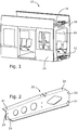
- FIG. 1 is now referred to where a railcar body 10 is shown.
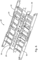
- the body 10 comprises an underframe assembly 12, side walls 14, a roof 16 and end walls 18. All these assemblies of the body 10 are made either of laser cut sheet components 20, of laser cut plate components 22 or of a combination of both, best shown in Figures 2 and 3 now concurrently referred to.
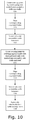
- the assemblies are made of sheet components 20, of plate components 22 or of a combination of both, they will be manufactured respectively either from a sheet assembly method, a plate assembly method, or a combination of both called hybrid assembly method, as will be described herein.
- Figure 9 showing a schematic of these three assembly methods, is concurrently referred to.
- sheet components 20 and plate components 22 Before any assembly methods may be started, sheet components 20 and plate components 22 must be provided.
- the sheet components 20 are made of sheet metal that is substantially thinner than 3,175 mm (1/8 inch) while the plate components 22 are made of metal plates substantially equal to or thicker than 3,175 mm (1/8 inch). Note that 3,175 mm (1/8 inch) is not an absolute limit, but is rather based on experience. Consequently, this threshold between the definition of sheet components and plate components should be understood as an approximate guideline rather than a precise measure to be respected.
- Both the sheet components 20 and the plate components 22 are made by a robot that laser cuts a blank sheet or plate 100 of metal which is then bent or folded 102 as required.
- the sheet component 20 is bent whereas in the example shown in Figure 3 , the plate component is flat. Note that this is just an example as it could be the reverse.
- all details and corresponding assembly features are readily cut in the sheet or plate component 20, 22, including its outline, holes, openings, tabs, notches, slots, or other male-female types of corresponding features. This ensures the required precision of all features of the sheet or plate component 20, 22 so that sheet and plate components 20, 22 may be assembled easily and precisely with each other.
- laser cutting equipment or robots are capable of a precision in the order of 0.1 mm (0.005 inch).
- cut features are present to remove weight from the component whereas other features (the corresponding assembly features) are used to precisely locate the sheet or plate component 20, 22 with respect to another sheet or plate component 20, 22 at a later stage.
- Such features are corresponding alignment holes 24, typically present in the sheet component 20 and in some plate components 22 as well as matching assembly details 25 typically present in the plate component 22.
- the process of manufacturing the railcar body 10 therefore first involves providing, by laser cutting and folding/bending, at least all required sheet and plate components 20, 22 to assemble the floor 12, two side walls 14, the roof 16 and two end walls 18.
- the floor 12, the side walls 14, the roof 16 and the end walls 18 are herein referred to as assemblies.
- the manufacturing of these assemblies may be completed without using any type of external tooling to hold sheet and plate components 20, 22 together as will be further explained later. It may however be useful to use a flat, level working table to assemble sheet and plate components 20, 22 of the floor 12, side walls 14, roof 16 and end walls 18, making it easier to lay one or more major component flat on the working table and then attach the other components to this one, or more, major component.
- the working table may be provided with wheels, air cushion, or other means enabling to move the working table around.
- end frames 26, used at each end of the underframe assembly 12 are manufactured from plate components 22 since they must meet static load cases requirement and then must absorb energy in case of a crash, thereby requiring added strength.
- These end frames 26 are connected to an underframe 28, itself made from sheet components.
- the underframe assembly 12 is therefore made using the hybrid assembly method, which comprises both the sheet assembly method and the plate assembly method.
- One end frame 26 will therefore first be used to illustrate the plate assembly method.
- the end frame 26 is assembled by first mounting plate components 22 to one another and by engaging 104 their matching assembly details 25.
- These matching assembly details 25 are mechanical features such as tongue and groove, mortise and tenon (any type of mortise and tenon: open mortise, stub mortise, wedged-half mortise (dovetail) or through mortise) or any other adequate assembly feature capable of precisely locating two adjacent plate components 22.
- the matching assembly details 25 are operative to secure in at least four, and possibly five, orthogonal directions the plate components 22. It is understood here that each one of the three orthogonal axes X, Y and Z comprises two opposite directions.
- the matching assembly details 25 are designed with a fit allowing to assemble the plate components 22 with each other using a slight force.
- Such fit may be, for example, a Location or Transition Fit.
- the laser welding robot proceeds to weld each plate component 22 on at least a portion of the joint between each pair of adjacent plate components 22.
- the plate components 22 have been designed to mostly create butt joints when assembled together (whether it is for a flat or a corner joint). Consequently, a robotically-controlled laser welding head is used mostly or solely to create butt welds.
- avoiding creating fillet welds also contribute to avoiding having recourse to external tooling since fillet welds require heat to be supplied on a larger area and since the fillet tends to pull on the welded parts when it cools down.
- the welds are created either along the whole thicknesses of two coplanar adjacent plate components 22 or along the whole thickness of a first plate component 22 and along a corresponding portion of a surface of an adjacent perpendicular plate component 22.
- no joint preparation operation is required since the joints may be laser welded directly as they were laser cut in the laser cutting operation 100.
- the cold wire used with the laser welding process 108 is sufficient to provide a required small quantity of material to complete the joints.
- the robot's welding head must of course be provided with adequate power to weld the plate components 22 through their whole thickness, which is typically at least 3,175 mm (1/8 inch).
- the laser welding head is usually equipped with a camera to detect joint characteristics and adapt parameters of the welding head in real time during the laser welding operation 108. Also, because the laser welding operation is performed by a high precision robot, it is possible to precisely follow the joints to be welded between two adjacent plate components 22. Focusing the laser beam of the welding head on a small area also contributes to avoiding the use of external tooling to hold the plate components 22. Indeed, conventional welding methods diffuse their heat on a relatively large area, inducing deformations in welded parts if they are not held in place by external tooling. Conversely, laser welding as used in the instant invention does not diffuse its heat on a large area, contributing to avoiding the use of external tooling.
- plate components 22 With precise dimensions and with precise matching assembly details 25 so that plate components 22 may be precisely assembled together.
- the laser welding process 108 as well as the type of joints and weld (butt joint and butt weld) have been carefully selected because they allow no significant deformation of the plate components 22 during the welding process 108. All these attributes make it possible to manufacture an assembly, such as the end frame 26, made of plate components 22 without any external tooling other than a flat and level surface (ground or table).
- the end wall 18 may be manufactured by using respectively either the plate assembly method as described above or the sheet assembly method which will now be described with concurrent reference to Figures 5 and 6 .
- the underframe 28, the two side walls 14 as well as the roof 16 are all similarly manufactured using the sheet assembly method since they are all made of sheet components 20.
- the underframe 28 will therefore now be used to illustrate the sheet assembly method.
- each sheet component 20 is made to at least partially overlap 110 at least one other sheet component 20, thereby defining overlapping pairs of sheet components 20.
- Each overlapping pair of sheet components 20 has its own corresponding lap joint 30 and each sheet component 20 has at least one matching alignment hole 24 in its lap joint 30.
- the corresponding alignment holes 24 of the overlapping pair of sheet components 20 are then aligned 112. This provides a precise orientation and location of the overlapping pair of sheet components 20 with respect to each other.
- Each sheet component 20 of the assembly being manufactured (the underframe 28 in the present example) is positioned and aligned with respect to another sheet component 20. Consequently, one sheet component 20 may be overlapped by more than one other sheet component and hence, may be part of more than one overlapping pair of sheet components 20 and may comprise more than one lap joint 30.
- the sheet components 20 are locked together 114 by using fasteners 32 inserted in the aligned corresponding alignment holes 24.
- the fasteners 32 are operative to secure along three orthogonal axes each sheet components 20. Because each sheet component 20 is precisely located with respect to another sheet component 20, it is possible to do without the use of tooling to hold the sheet components 20 together.
- the fasteners 32 may be rivets or bolts, it has been found that self-tapping screws provide the best combination of holding force and precise positioning.
- one of the sheet components 20 has a plain hole as its alignment hole 24 while the other sheet component 20 has a slightly smaller alignment hole 24, or an alignment hole 24 having protrusions extending radially towards its center, thereby making an effective portion of the alignment hole 24 with a smaller diameter.
- the self-tapping screw When the self-tapping screw is inserted, it is first inserted in the plain alignment hole 24 of the first sheet component 20 so that its threads may catch the smaller alignment hole 24, or the protrusions, to pull both sheet components 20 together.
- the underframe 28 may be transferred in the laser welding cell for being robotically laser welded.
- the laser welding robot welds 116 each pair of overlapping sheet components 20 in their lap joints 30.
- the lap joint 30 is the sole type of weld joint used in the assemblies made of sheet components 20 using the sheet assembly method.
- the sole type of weld used to weld these lap joints 30 is a melt-through weld where the welding occurs at the interface between both overlapped sheet components 20 through one of them.
- the laser welding robot creates this weld by encircling each fastener 32. In the present example, a circular weld 34 has been created.
- any appropriate weld pattern such as lines, zig-zags, waves, squares, etc, could be created similarly in the lap joint 30.
- the end frames 26 are typically made using the plate assembly method.
- the underframe 28, the side walls 14, and the roof 16 are typically made using the sheet assembly method.
- the end walls 18 are typically made using either one of these methods.
- the underframe assembly 12, shown in Figure 7 now concurrently referred to, is assembled by putting together the underframe 28 with at least one end frame 26 at one extremity and is therefore assembled using the hybrid assembly method.
- the underframe assembly 12 comprises two end frames 26, one at each extremity.
- the end frames 26 are mounted to the underframe assembly 12 by following a method which is similar to the sheet assembly method.
- the first step it to overlap 118 the underframe 28 with both end frames 26, thereby defining second lap joints 33.
- the second lap joints 33 are similar to lap joints 30 except that they occur between one sheet component 20 and one plate component 22.
- the corresponding alignment holes 24 of the underframe 28 and of the end frames 26 present in the second lap joints 33 are aligned together at 120.
- the end frames 26 and the underframe 28 are locked in position 122, or secured to each other, by using fasteners 32 inserted in the corresponding alignment holes 24.
- the fasteners 32 are inserted from the side of one sheet component 20 of the underframe 28 so as to tap in the thicker plates of one plate component 22 of the end frames 26.
- the end frames 26 are robotically laser welded 124 to the underframe 28 in the second lap joints 33. Again, the laser welding robot creates melt-through welds, either completely surrounding the fasteners 32, or in any adequate pattern. Finally, the fasteners 32 may be removed or left in place.
- the next step is to finally assemble the body 10 from the manufactured assemblies, namely the underframe assembly 12, the side walls 14, the roof 16 and the end walls 18.
- the side walls 14 are first installed by partially overlapping 126 the underframe assembly 12 on each side of the underframe assembly 12, thereby defining third lap joints 35.
- their corresponding alignment holes 24 are properly aligned 128.
- fasteners 32 are inserted in the alignment holes 24.
- the fasteners 32 may be tightened to bring in contact and secure 130 the side walls 14 to the underframe assembly 12. Alternatively, the fasteners 32 may be left loose until the remaining roof 16 and end walls 18 are installed at the next step.
- the roof 16 and the end walls 18 are then installed, the roof 16 partially overlapping 132 top portion of each side wall 14 in third lap joints 35 while the end walls 18 partially overlap the end portions of the underframe assembly 12, the side walls 14 and the roof 16 in third lap joints 35. Then the corresponding alignment holes 24 between each overlapped assembly are properly aligned 134. Note that the roof 16 may be installed before or after the end walls 18. Following this step, fasteners 32 are installed in the remaining corresponding alignment holes 24 of overlapping portions and then tightened to bring in contact and secure 136 the overlapped assemblies. If the fasteners 32 at the interface between the side walls 14 and the underframe assembly 12 were not tightened, they must be at this point.
- the assemblies may be robotically laser welded together 138 by laser welding the third lap joints 35 in the same fashion as performed for welding sheet components 20 together.
- the first lap joints 30, the second lap joints 33 and the third lap joints 35 are all lap joints.
- the third lap joint 35 may be similar to either the first lap joint 30 in that two sheet components 20 are overlapped, or it may be similar to the second lap joint 33 where one sheet component 20 overlaps a plate component 22.
- the type of weld used is the melt-through weld.
- the assemblies may only be fastened together by the fasteners 32. In this case, it is preferable to use permanent fasteners such as Huckbolts ® fasteners.
Landscapes
- Engineering & Computer Science (AREA)
- Mechanical Engineering (AREA)
- Life Sciences & Earth Sciences (AREA)
- Wood Science & Technology (AREA)
- Physics & Mathematics (AREA)
- Optics & Photonics (AREA)
- Plasma & Fusion (AREA)
- Laser Beam Processing (AREA)
- Automobile Manufacture Line, Endless Track Vehicle, Trailer (AREA)
- Automatic Assembly (AREA)
- Connection Of Plates (AREA)
Claims (13)
- Procédé de fabrication d'une carrosserie de wagon (10) comprenant :a) la fourniture d'une pluralité de composants de feuille métallique (20) découpés au laser par robot, chacun de la pluralité de composants de feuille métallique ayant un trou d'alignement découpé au laser ;b) la fabrication d'un châssis (28), d'une première paroi latérale (14), d'une seconde paroi latérale (14) et d'un toit (16) par :chevauchement partiel de chaque composant de feuille (20) d'un premier sous-ensemble de ladite pluralité de composants de feuille (20) avec un autre composant de feuille dudit premier sous-ensemble, définissant ainsi des paires chevauchantes de composants de feuille (20) et des premiers joints à recouvrement correspondants (30) ;alignement (112) de trous d'alignement (24) de chaque paire chevauchante de composants de feuille (24) dans leur premier joint à recouvrement commun (30) ;fixation (114) desdites paires chevauchantes de composants de feuille (20) à l'aide d'attaches (32) insérées dans lesdits trous d'alignement alignés (24), lesdites attaches (32) servant à fixer le long de trois axes orthogonaux lesdits composants de feuille (20) dudit premier sous-ensemble, évitant ainsi d'utiliser un outillage pour maintenir ensemble lesdits composants de feuille dudit premier sous-ensemble ; etsoudage au laser par robot (116) lesdites paires de composants de feuille se chevauchant (20) dans lesdits premiers joints à recouvrement (30) ;c) la fourniture d'un cadre d'extrémité (26) ;d) l'assemblage d'un ensemble de châssis (12) en assemblant ledit châssis (28) avec ledit châssis d'extrémité (26) ;e) la fourniture une paroi d'extrémité (18) ;f) l'assemblage de la carrosserie (10) en fixant ensemble ledit assemblage de châssis (12), lesdites première et seconde parois latérales (14), ladite paroi d'extrémité (18) et ledit toit (16),caractérisé en ce qu'il comprend en outre :
g) la fourniture d'une pluralité de composants de plaque métallique (22) découpés au laser par robot, chacun de ladite pluralité de composants de plaque (22) ayant un élément d'assemblage correspondant (25), chacun de ladite pluralité de composants de feuille (20) ayant une première épaisseur, chacun de ladite pluralité de composants de plaque (22) ayant une seconde épaisseur, ladite première épaisseur étant plus petite que ladite seconde épaisseur ;dans lequel l'étape c) comprend en outre :le montage (104) de chaque composant de plaque (22) d'un deuxième sous-ensemble de ladite pluralité d'composants de plaque (22) de manière adjacente à un autre composant de plaque (22) dudit deuxième sous-ensemble de telle sorte qu'au moins un desdits éléments d'assemblage correspondants (25) de chaque composant de plaque (22) vient en prise avec un autre dit élément d'assemblage correspondant (25) dudit autre composant de plaque adjacent (22), lesdits éléments d'assemblage correspondant (25) étant fonctionnels pour fixer, dans au moins quatre directions orthogonales, lesdits composants de plaque (22) dudit deuxième sous-ensemble et éviter ainsi d'utiliser un outillage pour maintenir ensemble lesdits composants de plaque (22) dudit deuxième sous-ensemble, ledit montage comprenant la création uniquement de joints bout à bout et de joints d'angle ;le soudage au laser par robot (108) desdits composants de plaque (22) dudit deuxième sous-ensemble ensemble le long d'au moins une partie desdits joints bout à bout et desdits joints d'angle créant ainsi uniquement des soudures bout à bout ; etdans lequel l'étape d) comprend en outre :le chevauchement partiel (118) dudit châssis (28) avec ledit châssis d'extrémité (26), définissant ainsi un deuxième joint à recouvrement (33) ;l'alignement (120) de trous d'alignement correspondants (24) dudit châssis (28) et dudit cadre d'extrémité (26) dans ledit deuxième joint à recouvrement (33) ;la fixation (122) dudit cadre d'extrémité (26) avec ledit châssis (28) à l'aide des attaches (32) insérées dans lesdits trous d'alignement alignés (24), lesdites attaches (32) étant opérationnelles pour fixer, le long de trois axes orthogonaux, ledit cadre d'extrémité (26) audit châssis (28), évitant ainsi d'utiliser un outillage pour maintenir ensemble ledit châssis d'extrémité audit châssis ; etle soudage au laser par robot (124) dudit cadre d'extrémité (26) audit châssis (28) dans lesdits deuxièmes joints à recouvrement (33) créant ainsi uniquement des soudures traversées. - Procédé selon la revendication 1, caractérisé en ce que l'étape e) comprend la fabrication de ladite paroi d'extrémité (26) par :montage de composants de plaque (22) d'un troisième sous-ensemble de ladite pluralité de composants de plaque (22) de manière adjacente de telle sorte qu'au moins l'un desdits éléments d'assemblage correspondants (25) desdits composants de plaque adjacents (22) dudit troisième sous-ensemble viennent en prise ensemble, ledit montage créant uniquement des joints bout à bout et des joints d'angle ; etsoudage au laser par robot (108) desdits composants de plaque (22) dudit troisième sous-ensemble ensemble le long d'au moins une partie desdits joints bout à bout et desdits joints d'angle, créant ainsi uniquement des soudures bout à bout.
- Procédé selon l'une quelconque des revendications 1 et 2, caractérisé en ce que l'étape f) comprend en outre :le chevauchement partiel (126) dudit ensemble de châssis (12) avec ladite première paroi latérale (14) et avec ladite seconde paroi latérale (14), le chevauchement partiel de ladite première paroi latérale (14) et de ladite seconde paroi latérale (14) avec ledit toit (16), le chevauchement partiel dudit assemblage de châssis (12), desdites première et seconde parois latérales (14) et dudit toit (16) avec deux desdites parois d'extrémité (18) définissant ainsi des troisièmes joints à recouvrement (35) des sous-ensembles chevauchés ;l'alignement (128) de trous d'alignement correspondants (24) desdits sous-ensembles superposés dans lesdits troisièmes joints à recouvrement (35) ;la fixation (130) desdits sous-ensembles superposés à l'aide d'attaches (32) insérées dans lesdits trous d'alignement alignés correspondants (24), lesdites attaches (32) servant à fixer, le long de trois axes orthogonaux, lesdits sous-ensembles superposés, évitant ainsi d'utiliser un outillage pour maintenir ensemble lesdits sous-ensembles superposés ; etle soudage au laser par robot (124) desdits sous-ensembles superposés ensemble dans lesdits troisièmes joints à recouvrement (35) créant ainsi exclusivement des soudures traversées.
- Procédé selon l'une quelconque des revendications 1 à 3, caractérisé en ce que ledit soudage au laser par robot (116) desdites paires de composants de feuille se chevauchant (22) dans leurs premiers joints à recouvrement (30) communs comprend le soudage autour d'une tête de chacune desdites attaches (32).
- Procédé selon la revendication 4, caractérisé en ce que ledit soudage au laser par robot (124) dudit cadre d'extrémité (26) audit châssis (28) dans lesdits deuxièmes joints à recouvrement (33) comprend le soudage autour de ladite tête de chacune desdites attaches (32).
- Procédé selon la revendication 5, caractérisé en ce que ledit soudage au laser par robot desdits sous-ensembles superposés ensemble dans ledit troisième joint à recouvrement (35) comprend le soudage autour de ladite tête de chacun desdites attaches (32).
- Procédé selon l'une quelconque des revendications 1 à 6, caractérisé en ce que l'étape c) comprend le soudage de pointage (106) desdits composants de plaque (22) ensemble avant ledit soudage au laser par robot desdits composants de plaque (22) ensemble.
- Procédé selon l'une quelconque des revendications 1 à 7, caractérisé en ce que ledit élément d'assemblage correspondant (25) de chacun desdits composants de plaque (22) est un tenon ou une mortaise.
- Procédé selon l'une quelconque des revendications 1 à 8, caractérisé en ce que ledit cadre d'extrémité (26) est dépourvu de soudures d'angle.
- Procédé selon l'une quelconque des revendications 1 à 9, caractérisé en ce que ladite première épaisseur est sensiblement inférieure à 3,175 mm (1/8 pouce) et en ce que ladite seconde épaisseur est sensiblement d'au moins 3,175 mm (1/8 pouce).
- Procédé selon l'une quelconque des revendications 1 à 10, caractérisé en ce que lesdites attaches (25) sont des vis autotaraudeuses et en ce que lesdites paires chevauchantes de composants de feuille (20) comprennent un premier composant de feuille (20) et un second composant de feuille (20), ledit trou d'alignement correspondant (24) dudit second composant de feuille (20) ayant un diamètre plus petit que ledit trou d'alignement correspondant (24) dudit premier composant de feuille (20), ledit procédé comprenant en outre le taraudage d'une dite attache (25) dans ledit trou d'alignement (24) dudit second composant de feuille (20) à travers ledit trou d'alignement correspondant (24) dudit premier composant de feuille (20).
- Procédé selon l'une quelconque des revendications 1 à 11, caractérisé en ce qu'il comprend en outre le retrait desdites attaches (25) une fois que ledit soudage au laser par robot est terminé.
- Carrosserie de wagon (10) fabriquée par le procédé de l'une quelconque des revendications 1 à 12.
Priority Applications (7)
| Application Number | Priority Date | Filing Date | Title |
|---|---|---|---|
| PL19204307T PL3812233T3 (pl) | 2019-10-21 | 2019-10-21 | Sposób wytwarzania nadwozia wagonu |
| EP19204307.3A EP3812233B1 (fr) | 2019-10-21 | 2019-10-21 | Procédé de fabrication d'un corps de wagon |
| ES19204307T ES2905433T3 (es) | 2019-10-21 | 2019-10-21 | Método para fabricar una carrocería de vagón |
| CA3096031A CA3096031C (fr) | 2019-10-21 | 2020-10-13 | Méthode de fabrication d’un corps de wagon |
| US17/074,796 US10994377B1 (en) | 2019-10-21 | 2020-10-20 | Method for manufacturing a railcar body |
| CN202011131068.5A CN112756820B (zh) | 2019-10-21 | 2020-10-21 | 铁路车体的制造方法 |
| AU2020257098A AU2020257098B2 (en) | 2019-10-21 | 2020-10-21 | Method for manufacturing a railcar body |
Applications Claiming Priority (1)
| Application Number | Priority Date | Filing Date | Title |
|---|---|---|---|
| EP19204307.3A EP3812233B1 (fr) | 2019-10-21 | 2019-10-21 | Procédé de fabrication d'un corps de wagon |
Publications (2)
| Publication Number | Publication Date |
|---|---|
| EP3812233A1 EP3812233A1 (fr) | 2021-04-28 |
| EP3812233B1 true EP3812233B1 (fr) | 2022-01-05 |
Family
ID=68296245
Family Applications (1)
| Application Number | Title | Priority Date | Filing Date |
|---|---|---|---|
| EP19204307.3A Active EP3812233B1 (fr) | 2019-10-21 | 2019-10-21 | Procédé de fabrication d'un corps de wagon |
Country Status (7)
| Country | Link |
|---|---|
| US (1) | US10994377B1 (fr) |
| EP (1) | EP3812233B1 (fr) |
| CN (1) | CN112756820B (fr) |
| AU (1) | AU2020257098B2 (fr) |
| CA (1) | CA3096031C (fr) |
| ES (1) | ES2905433T3 (fr) |
| PL (1) | PL3812233T3 (fr) |
Families Citing this family (3)
| Publication number | Priority date | Publication date | Assignee | Title |
|---|---|---|---|---|
| CN113954096A (zh) * | 2021-11-17 | 2022-01-21 | 北京中车重工机械有限公司 | 车厢切割系统及车厢切割方法 |
| CN114227045B (zh) * | 2021-12-23 | 2023-05-09 | 中铁九桥工程有限公司 | 一种钢桁梁弦杆节点板的反变形结构及其反变形方法 |
| ES3058365T3 (es) * | 2022-01-20 | 2026-03-10 | Alstom Holdings | Método de ensamblaje de un módulo interior en la carrocería de un coche de un vehículo ferroviario y carrocería de coche asociada |
Family Cites Families (14)
| Publication number | Priority date | Publication date | Assignee | Title |
|---|---|---|---|---|
| DE3733568A1 (de) * | 1987-10-03 | 1989-04-20 | Thyssen Industrie | Verfahren zur herstellung von schweissverbindungen an karosserieteilen und anderen blechteilen und robotersystem |
| DE19521892C1 (de) * | 1995-06-16 | 1996-08-08 | Waggonfabrik Talbot Gmbh & Co | Flächenelement und Verfahren zu dessen Herstellung |
| CA2221009A1 (fr) * | 1996-11-19 | 1998-05-19 | Powerlasers Ltd. | Joint auto-alignant pour le soudage des metaux au laser |
| DE10301276B4 (de) * | 2003-01-15 | 2014-12-24 | Siemens Aktiengesellschaft | Fahrweg eines Magnetschwebefahrzeugs |
| JP2008055952A (ja) * | 2006-08-29 | 2008-03-13 | Tokyu Car Corp | 鉄道車両台車用の構造物及びその製造方法 |
| JP2008068816A (ja) * | 2006-09-15 | 2008-03-27 | Tokyu Car Corp | 鉄道車両用構体及びその製造方法 |
| JP5038123B2 (ja) * | 2007-12-27 | 2012-10-03 | 近畿車輌株式会社 | 鉄道車両構体の重ねレーザ溶接方法、重ねレーザ溶接継手、鉄道車両の構体構造 |
| JP2010083214A (ja) * | 2008-09-29 | 2010-04-15 | Nippon Sharyo Seizo Kaisha Ltd | 鉄道車両および鉄道車両の製造方法 |
| JP5432733B2 (ja) * | 2010-01-14 | 2014-03-05 | 株式会社日立製作所 | 鉄道車両構体 |
| JP5470074B2 (ja) * | 2010-02-05 | 2014-04-16 | 株式会社総合車両製作所 | 鉄道車両構体及びその製造方法 |
| US9021703B2 (en) * | 2010-10-15 | 2015-05-05 | Norco Industries, Inc. | Method of manufacturing a roof bow |
| EP2704938B1 (fr) * | 2011-05-04 | 2016-01-13 | Bombardier Transportation GmbH | Caisse de véhicule ferroviaire et son procédé de fabrication |
| JP6185726B2 (ja) | 2013-02-25 | 2017-08-23 | 川崎重工業株式会社 | 鉄道車両構体 |
| FR3052422B1 (fr) | 2016-06-09 | 2019-08-30 | Alstom Transport Technologies | Structure de caisse de vehicule ferroviaire et procede d'assemblage d'une telle structure de caisse |
-
2019
- 2019-10-21 PL PL19204307T patent/PL3812233T3/pl unknown
- 2019-10-21 ES ES19204307T patent/ES2905433T3/es active Active
- 2019-10-21 EP EP19204307.3A patent/EP3812233B1/fr active Active
-
2020
- 2020-10-13 CA CA3096031A patent/CA3096031C/fr active Active
- 2020-10-20 US US17/074,796 patent/US10994377B1/en active Active
- 2020-10-21 AU AU2020257098A patent/AU2020257098B2/en active Active
- 2020-10-21 CN CN202011131068.5A patent/CN112756820B/zh active Active
Also Published As
| Publication number | Publication date |
|---|---|
| US10994377B1 (en) | 2021-05-04 |
| CN112756820A (zh) | 2021-05-07 |
| PL3812233T3 (pl) | 2022-05-02 |
| US20210114631A1 (en) | 2021-04-22 |
| CN112756820B (zh) | 2024-08-02 |
| CA3096031A1 (fr) | 2021-04-21 |
| CA3096031C (fr) | 2025-05-13 |
| AU2020257098B2 (en) | 2022-02-03 |
| AU2020257098A1 (en) | 2021-05-06 |
| EP3812233A1 (fr) | 2021-04-28 |
| ES2905433T3 (es) | 2022-04-08 |
Similar Documents
| Publication | Publication Date | Title |
|---|---|---|
| AU2020257098B2 (en) | Method for manufacturing a railcar body | |
| CN103596810B (zh) | 保险杠组件及方法 | |
| EP0785121A1 (fr) | Véhicule ferroviaire et méthode de construction | |
| US9487244B2 (en) | Structural component and a method of manufacturing such a component | |
| US11485414B2 (en) | Crossmember and manufacturing method for crossmember | |
| US8017887B2 (en) | Method for connecting components by local cold joining, using for example rivets or screws and laser welding | |
| US6374750B1 (en) | Structural panel system | |
| JP2005239029A (ja) | 鉄道車両構体 | |
| JP5342532B2 (ja) | 車体フレームの製造方法 | |
| WO2024187771A1 (fr) | Système d'assemblage flexible multi-robots pour assembler des parties de panneau d'aéronef | |
| JP2005066643A (ja) | パネル接合構造 | |
| JP2508388B2 (ja) | レ―ザ溶接方法 | |
| JPH106071A (ja) | 鋼板構成品の溶接方法及び溶接構造物 | |
| JP2019093959A (ja) | 車両構造材 | |
| CA3111262C (fr) | Structure de plancher d`un vehicule a rail et methode de fabrication de cette structure de plancher | |
| JP3313338B2 (ja) | パネル製造方法、鉄道車両構体及びパネル | |
| JPH0323908Y2 (fr) | ||
| JPH06270797A (ja) | 車両構体製作方法 | |
| US20220281491A1 (en) | Floor Structure of a Rail Vehicle and Method of Manufacturing Such Floor Structure | |
| KR100278789B1 (ko) | 철도차량의 제작방법 | |
| JPH051505Y2 (fr) | ||
| CN114889707A (zh) | 一种车身结构、车辆和车身结构的装配方法 | |
| JP2007077643A (ja) | 鉄骨建造物の既設鉄骨部材の補強方法及び補強構造 | |
| JP2012171496A (ja) | 交通車両の構体同士の接合構造、及び交通車両 | |
| JPS6327010Y2 (fr) |
Legal Events
| Date | Code | Title | Description |
|---|---|---|---|
| PUAI | Public reference made under article 153(3) epc to a published international application that has entered the european phase |
Free format text: ORIGINAL CODE: 0009012 |
|
| STAA | Information on the status of an ep patent application or granted ep patent |
Free format text: STATUS: REQUEST FOR EXAMINATION WAS MADE |
|
| 17P | Request for examination filed |
Effective date: 20201021 |
|
| AK | Designated contracting states |
Kind code of ref document: A1 Designated state(s): AL AT BE BG CH CY CZ DE DK EE ES FI FR GB GR HR HU IE IS IT LI LT LU LV MC MK MT NL NO PL PT RO RS SE SI SK SM TR |
|
| AX | Request for extension of the european patent |
Extension state: BA ME |
|
| GRAP | Despatch of communication of intention to grant a patent |
Free format text: ORIGINAL CODE: EPIDOSNIGR1 |
|
| STAA | Information on the status of an ep patent application or granted ep patent |
Free format text: STATUS: GRANT OF PATENT IS INTENDED |
|
| INTG | Intention to grant announced |
Effective date: 20210715 |
|
| RIN1 | Information on inventor provided before grant (corrected) |
Inventor name: LAFLAMME, MARTIN |
|
| GRAS | Grant fee paid |
Free format text: ORIGINAL CODE: EPIDOSNIGR3 |
|
| GRAA | (expected) grant |
Free format text: ORIGINAL CODE: 0009210 |
|
| STAA | Information on the status of an ep patent application or granted ep patent |
Free format text: STATUS: THE PATENT HAS BEEN GRANTED |
|
| AK | Designated contracting states |
Kind code of ref document: B1 Designated state(s): AL AT BE BG CH CY CZ DE DK EE ES FI FR GB GR HR HU IE IS IT LI LT LU LV MC MK MT NL NO PL PT RO RS SE SI SK SM TR |
|
| REG | Reference to a national code |
Ref country code: GB Ref legal event code: FG4D |
|
| REG | Reference to a national code |
Ref country code: CH Ref legal event code: EP |
|
| REG | Reference to a national code |
Ref country code: AT Ref legal event code: REF Ref document number: 1460289 Country of ref document: AT Kind code of ref document: T Effective date: 20220115 |
|
| REG | Reference to a national code |
Ref country code: DE Ref legal event code: R096 Ref document number: 602019010620 Country of ref document: DE |
|
| REG | Reference to a national code |
Ref country code: IE Ref legal event code: FG4D |
|
| REG | Reference to a national code |
Ref country code: ES Ref legal event code: FG2A Ref document number: 2905433 Country of ref document: ES Kind code of ref document: T3 Effective date: 20220408 |
|
| REG | Reference to a national code |
Ref country code: LT Ref legal event code: MG9D |
|
| REG | Reference to a national code |
Ref country code: NL Ref legal event code: MP Effective date: 20220105 |
|
| PG25 | Lapsed in a contracting state [announced via postgrant information from national office to epo] |
Ref country code: NL Free format text: LAPSE BECAUSE OF FAILURE TO SUBMIT A TRANSLATION OF THE DESCRIPTION OR TO PAY THE FEE WITHIN THE PRESCRIBED TIME-LIMIT Effective date: 20220105 |
|
| PG25 | Lapsed in a contracting state [announced via postgrant information from national office to epo] |
Ref country code: SE Free format text: LAPSE BECAUSE OF FAILURE TO SUBMIT A TRANSLATION OF THE DESCRIPTION OR TO PAY THE FEE WITHIN THE PRESCRIBED TIME-LIMIT Effective date: 20220105 Ref country code: RS Free format text: LAPSE BECAUSE OF FAILURE TO SUBMIT A TRANSLATION OF THE DESCRIPTION OR TO PAY THE FEE WITHIN THE PRESCRIBED TIME-LIMIT Effective date: 20220105 Ref country code: PT Free format text: LAPSE BECAUSE OF FAILURE TO SUBMIT A TRANSLATION OF THE DESCRIPTION OR TO PAY THE FEE WITHIN THE PRESCRIBED TIME-LIMIT Effective date: 20220505 Ref country code: NO Free format text: LAPSE BECAUSE OF FAILURE TO SUBMIT A TRANSLATION OF THE DESCRIPTION OR TO PAY THE FEE WITHIN THE PRESCRIBED TIME-LIMIT Effective date: 20220405 Ref country code: LT Free format text: LAPSE BECAUSE OF FAILURE TO SUBMIT A TRANSLATION OF THE DESCRIPTION OR TO PAY THE FEE WITHIN THE PRESCRIBED TIME-LIMIT Effective date: 20220105 Ref country code: HR Free format text: LAPSE BECAUSE OF FAILURE TO SUBMIT A TRANSLATION OF THE DESCRIPTION OR TO PAY THE FEE WITHIN THE PRESCRIBED TIME-LIMIT Effective date: 20220105 Ref country code: BG Free format text: LAPSE BECAUSE OF FAILURE TO SUBMIT A TRANSLATION OF THE DESCRIPTION OR TO PAY THE FEE WITHIN THE PRESCRIBED TIME-LIMIT Effective date: 20220405 |
|
| PG25 | Lapsed in a contracting state [announced via postgrant information from national office to epo] |
Ref country code: LV Free format text: LAPSE BECAUSE OF FAILURE TO SUBMIT A TRANSLATION OF THE DESCRIPTION OR TO PAY THE FEE WITHIN THE PRESCRIBED TIME-LIMIT Effective date: 20220105 Ref country code: GR Free format text: LAPSE BECAUSE OF FAILURE TO SUBMIT A TRANSLATION OF THE DESCRIPTION OR TO PAY THE FEE WITHIN THE PRESCRIBED TIME-LIMIT Effective date: 20220406 Ref country code: FI Free format text: LAPSE BECAUSE OF FAILURE TO SUBMIT A TRANSLATION OF THE DESCRIPTION OR TO PAY THE FEE WITHIN THE PRESCRIBED TIME-LIMIT Effective date: 20220105 |
|
| PG25 | Lapsed in a contracting state [announced via postgrant information from national office to epo] |
Ref country code: IS Free format text: LAPSE BECAUSE OF FAILURE TO SUBMIT A TRANSLATION OF THE DESCRIPTION OR TO PAY THE FEE WITHIN THE PRESCRIBED TIME-LIMIT Effective date: 20220505 |
|
| REG | Reference to a national code |
Ref country code: DE Ref legal event code: R097 Ref document number: 602019010620 Country of ref document: DE |
|
| PG25 | Lapsed in a contracting state [announced via postgrant information from national office to epo] |
Ref country code: SM Free format text: LAPSE BECAUSE OF FAILURE TO SUBMIT A TRANSLATION OF THE DESCRIPTION OR TO PAY THE FEE WITHIN THE PRESCRIBED TIME-LIMIT Effective date: 20220105 Ref country code: SK Free format text: LAPSE BECAUSE OF FAILURE TO SUBMIT A TRANSLATION OF THE DESCRIPTION OR TO PAY THE FEE WITHIN THE PRESCRIBED TIME-LIMIT Effective date: 20220105 Ref country code: RO Free format text: LAPSE BECAUSE OF FAILURE TO SUBMIT A TRANSLATION OF THE DESCRIPTION OR TO PAY THE FEE WITHIN THE PRESCRIBED TIME-LIMIT Effective date: 20220105 Ref country code: EE Free format text: LAPSE BECAUSE OF FAILURE TO SUBMIT A TRANSLATION OF THE DESCRIPTION OR TO PAY THE FEE WITHIN THE PRESCRIBED TIME-LIMIT Effective date: 20220105 Ref country code: DK Free format text: LAPSE BECAUSE OF FAILURE TO SUBMIT A TRANSLATION OF THE DESCRIPTION OR TO PAY THE FEE WITHIN THE PRESCRIBED TIME-LIMIT Effective date: 20220105 |
|
| PLBE | No opposition filed within time limit |
Free format text: ORIGINAL CODE: 0009261 |
|
| STAA | Information on the status of an ep patent application or granted ep patent |
Free format text: STATUS: NO OPPOSITION FILED WITHIN TIME LIMIT |
|
| PG25 | Lapsed in a contracting state [announced via postgrant information from national office to epo] |
Ref country code: AL Free format text: LAPSE BECAUSE OF FAILURE TO SUBMIT A TRANSLATION OF THE DESCRIPTION OR TO PAY THE FEE WITHIN THE PRESCRIBED TIME-LIMIT Effective date: 20220105 |
|
| 26N | No opposition filed |
Effective date: 20221006 |
|
| REG | Reference to a national code |
Ref country code: AT Ref legal event code: UEP Ref document number: 1460289 Country of ref document: AT Kind code of ref document: T Effective date: 20220105 |
|
| PG25 | Lapsed in a contracting state [announced via postgrant information from national office to epo] |
Ref country code: SI Free format text: LAPSE BECAUSE OF FAILURE TO SUBMIT A TRANSLATION OF THE DESCRIPTION OR TO PAY THE FEE WITHIN THE PRESCRIBED TIME-LIMIT Effective date: 20220105 |
|
| PG25 | Lapsed in a contracting state [announced via postgrant information from national office to epo] |
Ref country code: MC Free format text: LAPSE BECAUSE OF FAILURE TO SUBMIT A TRANSLATION OF THE DESCRIPTION OR TO PAY THE FEE WITHIN THE PRESCRIBED TIME-LIMIT Effective date: 20220105 |
|
| REG | Reference to a national code |
Ref country code: BE Ref legal event code: MM Effective date: 20221031 |
|
| PG25 | Lapsed in a contracting state [announced via postgrant information from national office to epo] |
Ref country code: LU Free format text: LAPSE BECAUSE OF NON-PAYMENT OF DUE FEES Effective date: 20221021 |
|
| PG25 | Lapsed in a contracting state [announced via postgrant information from national office to epo] |
Ref country code: IT Free format text: LAPSE BECAUSE OF FAILURE TO SUBMIT A TRANSLATION OF THE DESCRIPTION OR TO PAY THE FEE WITHIN THE PRESCRIBED TIME-LIMIT Effective date: 20220105 |
|
| P01 | Opt-out of the competence of the unified patent court (upc) registered |
Effective date: 20230822 |
|
| PG25 | Lapsed in a contracting state [announced via postgrant information from national office to epo] |
Ref country code: BE Free format text: LAPSE BECAUSE OF NON-PAYMENT OF DUE FEES Effective date: 20221031 |
|
| PG25 | Lapsed in a contracting state [announced via postgrant information from national office to epo] |
Ref country code: IE Free format text: LAPSE BECAUSE OF NON-PAYMENT OF DUE FEES Effective date: 20221021 |
|
| PG25 | Lapsed in a contracting state [announced via postgrant information from national office to epo] |
Ref country code: CY Free format text: LAPSE BECAUSE OF FAILURE TO SUBMIT A TRANSLATION OF THE DESCRIPTION OR TO PAY THE FEE WITHIN THE PRESCRIBED TIME-LIMIT Effective date: 20220105 |
|
| PG25 | Lapsed in a contracting state [announced via postgrant information from national office to epo] |
Ref country code: MK Free format text: LAPSE BECAUSE OF FAILURE TO SUBMIT A TRANSLATION OF THE DESCRIPTION OR TO PAY THE FEE WITHIN THE PRESCRIBED TIME-LIMIT Effective date: 20220105 Ref country code: HU Free format text: LAPSE BECAUSE OF FAILURE TO SUBMIT A TRANSLATION OF THE DESCRIPTION OR TO PAY THE FEE WITHIN THE PRESCRIBED TIME-LIMIT; INVALID AB INITIO Effective date: 20191021 |
|
| GBPC | Gb: european patent ceased through non-payment of renewal fee |
Effective date: 20231021 |
|
| PG25 | Lapsed in a contracting state [announced via postgrant information from national office to epo] |
Ref country code: GB Free format text: LAPSE BECAUSE OF NON-PAYMENT OF DUE FEES Effective date: 20231021 |
|
| PG25 | Lapsed in a contracting state [announced via postgrant information from national office to epo] |
Ref country code: GB Free format text: LAPSE BECAUSE OF NON-PAYMENT OF DUE FEES Effective date: 20231021 |
|
| PG25 | Lapsed in a contracting state [announced via postgrant information from national office to epo] |
Ref country code: MT Free format text: LAPSE BECAUSE OF FAILURE TO SUBMIT A TRANSLATION OF THE DESCRIPTION OR TO PAY THE FEE WITHIN THE PRESCRIBED TIME-LIMIT Effective date: 20220105 |
|
| REG | Reference to a national code |
Ref country code: CH Ref legal event code: U11 Free format text: ST27 STATUS EVENT CODE: U-0-0-U10-U11 (AS PROVIDED BY THE NATIONAL OFFICE) Effective date: 20251101 |
|
| PG25 | Lapsed in a contracting state [announced via postgrant information from national office to epo] |
Ref country code: TR Free format text: LAPSE BECAUSE OF FAILURE TO SUBMIT A TRANSLATION OF THE DESCRIPTION OR TO PAY THE FEE WITHIN THE PRESCRIBED TIME-LIMIT Effective date: 20220105 |
|
| PGFP | Annual fee paid to national office [announced via postgrant information from national office to epo] |
Ref country code: DE Payment date: 20251021 Year of fee payment: 7 |
|
| PGFP | Annual fee paid to national office [announced via postgrant information from national office to epo] |
Ref country code: AT Payment date: 20251022 Year of fee payment: 7 |
|
| PGFP | Annual fee paid to national office [announced via postgrant information from national office to epo] |
Ref country code: FR Payment date: 20251030 Year of fee payment: 7 |
|
| PGFP | Annual fee paid to national office [announced via postgrant information from national office to epo] |
Ref country code: CH Payment date: 20251101 Year of fee payment: 7 |
|
| PGFP | Annual fee paid to national office [announced via postgrant information from national office to epo] |
Ref country code: CZ Payment date: 20251015 Year of fee payment: 7 |
|
| PGFP | Annual fee paid to national office [announced via postgrant information from national office to epo] |
Ref country code: PL Payment date: 20251009 Year of fee payment: 7 |
|
| PGFP | Annual fee paid to national office [announced via postgrant information from national office to epo] |
Ref country code: ES Payment date: 20251216 Year of fee payment: 7 |