EP3812264A1 - Roue phonique et système et procédé correspondants - Google Patents
Roue phonique et système et procédé correspondants Download PDFInfo
- Publication number
- EP3812264A1 EP3812264A1 EP20203120.9A EP20203120A EP3812264A1 EP 3812264 A1 EP3812264 A1 EP 3812264A1 EP 20203120 A EP20203120 A EP 20203120A EP 3812264 A1 EP3812264 A1 EP 3812264A1
- Authority
- EP
- European Patent Office
- Prior art keywords
- tooth
- axial end
- sensor
- height
- axial
- Prior art date
- Legal status (The legal status is an assumption and is not a legal conclusion. Google has not performed a legal analysis and makes no representation as to the accuracy of the status listed.)
- Granted
Links
Images

Classifications
-
- B—PERFORMING OPERATIONS; TRANSPORTING
- B64—AIRCRAFT; AVIATION; COSMONAUTICS
- B64C—AEROPLANES; HELICOPTERS
- B64C11/00—Propellers, e.g. of ducted type; Features common to propellers and rotors for rotorcraft
- B64C11/30—Blade pitch-changing mechanisms
- B64C11/301—Blade pitch-changing mechanisms characterised by blade position indicating means
-
- B—PERFORMING OPERATIONS; TRANSPORTING
- B64—AIRCRAFT; AVIATION; COSMONAUTICS
- B64C—AEROPLANES; HELICOPTERS
- B64C11/00—Propellers, e.g. of ducted type; Features common to propellers and rotors for rotorcraft
- B64C11/30—Blade pitch-changing mechanisms
- B64C11/44—Blade pitch-changing mechanisms electric
-
- B—PERFORMING OPERATIONS; TRANSPORTING
- B64—AIRCRAFT; AVIATION; COSMONAUTICS
- B64D—EQUIPMENT FOR FITTING IN OR TO AIRCRAFT; FLIGHT SUITS; PARACHUTES; ARRANGEMENT OR MOUNTING OF POWER PLANTS OR PROPULSION TRANSMISSIONS IN AIRCRAFT
- B64D45/00—Aircraft indicators or protectors not otherwise provided for
-
- F—MECHANICAL ENGINEERING; LIGHTING; HEATING; WEAPONS; BLASTING
- F01—MACHINES OR ENGINES IN GENERAL; ENGINE PLANTS IN GENERAL; STEAM ENGINES
- F01D—NON-POSITIVE DISPLACEMENT MACHINES OR ENGINES, e.g. STEAM TURBINES
- F01D17/00—Regulating or controlling by varying flow
- F01D17/02—Arrangement of sensing elements
-
- F—MECHANICAL ENGINEERING; LIGHTING; HEATING; WEAPONS; BLASTING
- F01—MACHINES OR ENGINES IN GENERAL; ENGINE PLANTS IN GENERAL; STEAM ENGINES
- F01D—NON-POSITIVE DISPLACEMENT MACHINES OR ENGINES, e.g. STEAM TURBINES
- F01D17/00—Regulating or controlling by varying flow
- F01D17/20—Devices dealing with sensing elements or final actuators or transmitting means between them, e.g. power-assisted
- F01D17/22—Devices dealing with sensing elements or final actuators or transmitting means between them, e.g. power-assisted the operation or power assistance being predominantly non-mechanical
- F01D17/24—Devices dealing with sensing elements or final actuators or transmitting means between them, e.g. power-assisted the operation or power assistance being predominantly non-mechanical electrical
-
- F—MECHANICAL ENGINEERING; LIGHTING; HEATING; WEAPONS; BLASTING
- F01—MACHINES OR ENGINES IN GENERAL; ENGINE PLANTS IN GENERAL; STEAM ENGINES
- F01D—NON-POSITIVE DISPLACEMENT MACHINES OR ENGINES, e.g. STEAM TURBINES
- F01D21/00—Shutting-down of machines or engines, e.g. in emergency; Regulating, controlling, or safety means not otherwise provided for
- F01D21/003—Arrangements for testing or measuring
-
- F—MECHANICAL ENGINEERING; LIGHTING; HEATING; WEAPONS; BLASTING
- F01—MACHINES OR ENGINES IN GENERAL; ENGINE PLANTS IN GENERAL; STEAM ENGINES
- F01D—NON-POSITIVE DISPLACEMENT MACHINES OR ENGINES, e.g. STEAM TURBINES
- F01D7/00—Rotors with blades adjustable in operation; Control thereof
-
- G—PHYSICS
- G01—MEASURING; TESTING
- G01B—MEASURING LENGTH, THICKNESS OR SIMILAR LINEAR DIMENSIONS; MEASURING ANGLES; MEASURING AREAS; MEASURING IRREGULARITIES OF SURFACES OR CONTOURS
- G01B7/00—Measuring arrangements characterised by the use of electric or magnetic techniques
- G01B7/003—Measuring arrangements characterised by the use of electric or magnetic techniques for measuring position, not involving coordinate determination
-
- G—PHYSICS
- G01—MEASURING; TESTING
- G01B—MEASURING LENGTH, THICKNESS OR SIMILAR LINEAR DIMENSIONS; MEASURING ANGLES; MEASURING AREAS; MEASURING IRREGULARITIES OF SURFACES OR CONTOURS
- G01B7/00—Measuring arrangements characterised by the use of electric or magnetic techniques
- G01B7/02—Measuring arrangements characterised by the use of electric or magnetic techniques for measuring length, width or thickness
- G01B7/023—Measuring arrangements characterised by the use of electric or magnetic techniques for measuring length, width or thickness for measuring distance between sensor and object
-
- G—PHYSICS
- G01—MEASURING; TESTING
- G01P—MEASURING LINEAR OR ANGULAR SPEED, ACCELERATION, DECELERATION, OR SHOCK; INDICATING PRESENCE, ABSENCE, OR DIRECTION, OF MOVEMENT
- G01P3/00—Measuring linear or angular speed; Measuring differences of linear or angular speeds
- G01P3/42—Devices characterised by the use of electric or magnetic means
- G01P3/44—Devices characterised by the use of electric or magnetic means for measuring angular speed
- G01P3/48—Devices characterised by the use of electric or magnetic means for measuring angular speed by measuring frequency of generated current or voltage
- G01P3/481—Devices characterised by the use of electric or magnetic means for measuring angular speed by measuring frequency of generated current or voltage of pulse signals
- G01P3/488—Devices characterised by the use of electric or magnetic means for measuring angular speed by measuring frequency of generated current or voltage of pulse signals delivered by variable reluctance detectors
-
- F—MECHANICAL ENGINEERING; LIGHTING; HEATING; WEAPONS; BLASTING
- F05—INDEXING SCHEMES RELATING TO ENGINES OR PUMPS IN VARIOUS SUBCLASSES OF CLASSES F01-F04
- F05D—INDEXING SCHEME FOR ASPECTS RELATING TO NON-POSITIVE-DISPLACEMENT MACHINES OR ENGINES, GAS-TURBINES OR JET-PROPULSION PLANTS
- F05D2270/00—Control
- F05D2270/80—Devices generating input signals, e.g. transducers, sensors, cameras or strain gauges
Definitions
- the disclosure relates generally to phonic wheels and to feedback systems for pitch-adjustable blades of bladed rotors of aircraft.
- the disclosure describes a phonic wheel comprising: a body configured to rotate about a rotation axis; and a tooth attached to the body, the tooth having a first axial end relative to the rotation axis, a second axial end opposite the first axial end, and a mid portion extending between the first and second axial ends, the mid portion having a substantially axially uniform height from the body, the first axial end having a greater height from the body than the height of the mid portion.
- the disclosure describes a feedback system for pitch-adjustable blades of a bladed rotor coupled to an aircraft engine.
- the system comprises: a feedback rotor configured to rotate with the aircraft bladed rotor about a rotation axis, the feedback rotor being axially displaceable along the rotation axis to a plurality of axial positions, the axial position of the feedback rotor corresponding to a respective pitch position of the pitch-adjustable blades, the feedback rotor having: a body; and a tooth attached to the body, the tooth having a first axial end relative to the rotation axis, a second axial end opposite the first axial end, and a mid portion extending between the first and second axial ends, the mid portion having a substantially axially uniform height from the body, the first axial end having a greater height from the body than the height of the mid portion; and a sensor mounted adjacent the feedback rotor and configured to generate a sensor signal indicative of a proximity of the tooth to the sensor as the feedback
- the disclosure describes a method for providing a feedback signal using a phonic wheel.
- the method comprises: directing a magnetic field from a sensor toward a location that a tooth of the phonic wheel is expected to occupy as the tooth rotates relative to the sensor, the magnetic field including magnetic flux intersecting the location that the rotating tooth is expected to occupy, the tooth having a first axial end relative to a rotation axis of the tooth, a second axial end opposite the first axial end, and a mid portion extending between the first and second axial ends, the mid portion having a substantially axially uniform height, the first axial end having a greater height than the height of the mid portion; using the first axial end of the tooth to guide some of the magnetic flux intersecting the tooth; detecting (e.g., using the sensor) a variation in the magnetic field caused by movement of the tooth in the magnetic field; and generating (e.g., using a detector operatively connected to the sensor) a feedback signal based on the detection of the variation in
- a tooth of a phonic wheel may have a raised axial end relative to a mid portion of the tooth.
- the raised axial end of the tooth may guide some magnetic flux intersecting the tooth along one or more return paths to promote accurate detection of the passing of the tooth by the sensor as the phonic wheel rotates relative to the sensor.
- the use of a raised axial end on a tooth may reduced the need for additional axial length of the tooth.
- the phonic wheels, feedback systems and methods described herein may be useful in providing feedback on the angular (i.e., pitch) position of pitch-adjustable blades on aircraft bladed rotors such as aircraft propellers for example.
- the phonic wheels disclosed herein could also be used in other applications.
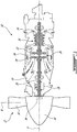
- FIG. 1 is an axial cross-section view of an exemplary aircraft engine 10 coupled to bladed rotor 12 (e.g., propeller) for an aircraft.
- Engine 10 may be a gas turbine engine, of a type typically provided for use in subsonic flight, comprising inlet 14, into which ambient air is received, (e.g., multi-stage) compressor 16 for pressurizing the air, combustor 18 in which the compressed air is mixed with fuel and ignited for generating an annular stream of hot combustion gases, and turbine section 20 for extracting energy from the combustion gases.
- gas turbine engine of a type typically provided for use in subsonic flight, comprising inlet 14, into which ambient air is received, (e.g., multi-stage) compressor 16 for pressurizing the air, combustor 18 in which the compressed air is mixed with fuel and ignited for generating an annular stream of hot combustion gases, and turbine section 20 for extracting energy from the combustion gases.
- Turbine section 20 may comprise high-pressure turbine 22, which may drive compressor 16 and other accessories, and power turbine 24 which may rotate independently from high-pressure turbine 22 and which may drive power shaft 26, which may be drivingly coupled to bladed rotor 12 via reduction gearbox 28.
- Combustion gases may be evacuated through exhaust duct 30 after passing through turbine section 20.
- Bladed rotor 12 may comprise a plurality of pitch-adjustable blades 32 extending radially from hub 34 and being circumferentially distributed relative to hub 34 of bladed rotor 12.
- Bladed rotor 12 may be a variable pitch bladed rotor where each blade 32 may be angularly adjustable about a respective axis B. Accordingly, each blade 32 may be rotatable about axis B using any suitable mechanism so that the pitch of blades 32 may be adjusted collectively in unison for different phases of operation (e.g., feather, forward thrust and reverse thrust) of engine 10 and/or of an aircraft to which engine 10 and bladed rotor 12 may be mounted.
- bladed rotor 12 as a propeller suitable for fixed-wing aircraft, it is understood that aspects of this disclosure are also applicable to other types of bladed rotors such as main rotors and tail rotors of rotary-wing aircraft such as helicopters for example.
- Bladed rotor 12 may be mounted for rotation about rotation axis R.
- rotation axis R may, but not necessarily, be coaxial with an axis of rotation of power shaft 26.
- FIG. 1 also schematically shows a feedback system 36 (referred hereinafter as “feedback system 36") associated with bladed rotor 12 and which is described below.
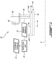
- FIG. 2 is a schematic representation of a partial axial cross-section of an exemplary feedback system 36.
- feedback system 36 may be a feedback system of engine 10 for providing feedback on the angular position of adjustable blades 32 of bladed rotor 12.
- Feedback system 36 may be configured to interface with known or other adjustable blade systems to permit the detection of the angular position (e.g., beta angle) of adjustable blades 32.
- feedback system 36 may comprise a phonic wheel 38, sensor 40 and detection unit 42.
- FIG. 2 shows the phonic wheel 38 as a feedback rotor integrated within an engine 10 for providing feedback on the angular position of adjustable blades 32 of bladed rotor 12.
- the feedback system 36 may be integrated within other systems to provide different forms of feedback.
- phonic wheel 38 may be configured to rotate with (e.g., be mechanically coupled to) bladed rotor 12 about rotation axis R.
- phonic wheel 38 may be configured to rotate at the same rotational speed and coaxially with bladed rotor 12.
- the rotation axis of phonic wheel 38 may not necessarily by coaxial with rotation axis R of bladed rotor 12.
- Phonic wheel 38 may be axially displaceable along rotation axis R to a plurality of axial positions where an axial position of phonic wheel 38 may correspond to a respective angular (pitch) position of adjustable blades 32.
- Phonic wheel 38 may comprise circumferentially-spaced apart teeth 44 useful for detecting the axial position of phonic wheel 38 as phonic wheel 38 and bladed rotor 12 rotate. Phonic wheel 38 may consequently be useful for detecting the angular position of adjustable blades 32 by way of a correlation.
- Phonic wheel 38 may comprise (e.g., annular) body 46 or wheel with teeth 44 attached thereto and protruding radially therefrom.
- teeth 44 and sensor 40 may be disposed on a radially-outer side of annular body 46.
- teeth 44 and sensor 40 could be disposed on a radially-inner side of annular body 46 instead.
- teeth 44 may be configured such that a passage of teeth 44 can be detected by sensor 40 as phonic wheel 38 rotates about rotation axis R. In various embodiments, teeth 44 may all be of the same geometric configuration or may comprise teeth of different geometric configurations. In some embodiments, one or more teeth 44 may be separate components individually secured to annular body 46 of phonic wheel 38. In some embodiments, one or more teeth 44 may be integrally formed with annular body 46 so that phonic wheel 38 may have a unitary construction.
- Phonic wheel 38 may be operatively coupled with bladed rotor 12 to permit the axial position of phonic wheel 38 to correspond with the angular position of adjustable blades 32.
- the operative coupling of phonic wheel 38 and bladed rotor 12 may be as described in US Patent Publication No. 2015/0139798 A1 (title: SYSTEM AND METHOD FOR ELECTRONIC PROPELLER BLADE ANGLE POSITION FEEDBACK).
- Sensor 40 may be an inductive (e.g., proximity) sensor suitable for non-contact detection of the passage of teeth 44 as phonic wheel 38 rotates about rotation axis R.
- Sensor 40 may be mounted adjacent phonic wheel 38 and secured to some stationary structure of engine 10 via bracket 48 for example or other suitable means.
- sensor 40 may be configured as a variable reluctance sensor (commonly called a VR sensor) suitable for detecting the proximity of (e.g., ferrous) teeth 44.
- teeth 44 may be configured to intersect a magnetic field generated by sensor 40 and cause a detectable variation in (e.g., disrupt) the magnetic field.
- the passage of each tooth 44 may cause a change in magnetic permeability within the magnetic field generated by sensor 40 and may consequently cause a detectable variation in the magnetic field.
- teeth 44 may comprise ferrous or other metallic material(s).
- Detection unit 42 may be operatively connected to sensor 40 for receiving one or more sensor signals 50 and configured to generate one or more feedback signals 52 indicative of the angular position of adjustable blades 32.
- detection unit 42 may form part of a Full Authority Digital Engine Control (FADEC) which may, for example, comprise one or more digital computer(s) or other data processors, sometimes referred to as electronic engine controller(s) (EEC) and related accessories that control at least some aspects of performance of engine 10.
- FADEC Full Authority Digital Engine Control
- detection unit 42 may comprise one or more computing devices including, but not limited to, a digital computer, a processor (e.g. a microprocessor), and a memory.
- sensor signal(s) 50 may also be used to provide feedback on the rotational speed of bladed rotor 12. Accordingly, detection unit 42 may, in some embodiments be configured to generate feedback signal(s) 52 indicative of the rotational speed of bladed rotor 12.
- feedback system 36 may be referred to as an "Np/beta" feedback system where Np represents the rotational speed of bladed rotor 12 and beta represents the angular position of adjustable blades 32.
- detection unit 42 may perform other tasks associated with functions such as synchronization and/or synchrophasing of propellers for example.
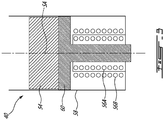
- FIG. 3 is a respective schematic front view of an exemplary sensor 40 of feedback system 36.
- Sensor 40 may comprise a magnet 54.
- Magnet 54 may be a permanent magnet that is stationary relative to phonic wheel 38.
- Magnet 54 may generate a magnetic field that intersects teeth 44 as phonic wheel 38 is rotated.
- Sensor 40 may have one or more coils 56A, 56B (also referred generally hereinafter as "coils 56") to generate one or more sensor signals 50 (see FIG. 2 ) in response to variations in the magnetic field caused by the movement of teeth 44.
- sensor 40 may include housing 58 and pole piece 60 configured to direct the magnetic field generated by magnet 54 toward phonic wheel 38 at a location expected to be occupied by teeth 44.
- Pole piece 60 may be coupled to one pole of magnet 54 and be configured to direct the magnetic field radially inwardly (or outwardly) generally along sensor axis SA and toward phonic wheel 38 so that the magnetic flux exiting the distal end of pole piece 60 may intersect teeth 44 as teeth 44 move past sensor 40.
- Pole piece 60 may be a structure comprising material of relatively high magnetic permeability that serves to direct the magnetic field generated by magnet 54 toward teeth 44.
- Pole piece 60 may be coupled to a pole of magnet 58 and in a sense extend the pole of magnet 54 toward phonic wheel 38.
- Pole piece 60 may be disposed between magnet 54 and phonic wheel 38.
- sensor 40 may have a single-channel configuration and accordingly may have a single coil configured to generate one or more sensor signals 50 in response to variations in the magnetic field caused by the movement of teeth 44.
- sensor 40 may have a multi-channel configuration wherein sensor signals 50 are acquired in a redundant manner.
- FIG. 3 shows an exemplary configuration of coils 56A and 56B for a two-channel configuration of sensor 40 where coils 56A and 56B are electrically-isolated from each other and may provide redundant sensor signals 50 in response to variations in the magnetic field.
- coil 56A may be configured to generate one or more first sensor signals 50 (e.g., voltages) on a first channel in response to the variations in the magnetic field
- coil 56B may be configured to generate one or more second sensor signals 50 (e.g., voltages) on a second channel in response to the variations in the magnetic field.
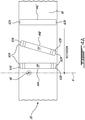
- FIG. 4A is a schematic top view of sensor 40 in relation to teeth 44A, 44B and 44C (also referred generally hereinafter as "teeth 44") about to be detected by sensor 40 as phonic wheel 38 rotates.
- FIG. 4B is a schematic side view of sensor 40 in relation to teeth 44 about to be detected by sensor 40 as phonic 38 rotates about rotation axis R.
- FIGS. 4A and 4B each show a portion of annular body 46 that has been flattened for clarity of illustration.
- Teeth 44 may have the form of elongated teeth or walls that protrude radially outwardly from a radially outer surface of annular body 46.
- Teeth 44 may comprise axial edges or terminations/faces 62A, 62B (also referred generally hereinafter as "axial edges 62") where elongated teeth 44 terminate in the axial direction relative to rotation axis R (see FIG. 2 ).
- axial edges 62 may be desirable to permit sensor 40 to be positioned near edges 62 and still be able to accurately detect the passing of teeth 44 despite any edge-related effects that may influence the magnetic field around sensor 40. This may allow to more fully use the axial dimension of phonic wheel 38 and promote efficient packaging of phonic wheel 38 by not requiring extra axial length of phonic wheel 38 for the purpose of avoiding such edge-related effects.
- the amount of axial travel of phonic wheel 38 may be dependent on the specific type of bladed rotor 12 and installation constraints.
- phonic wheel 38 may have one or more elongated teeth 44 that are substantially aligned with (i.e., parallel to) rotation axis R. In some embodiments, phonic wheel 38 may have one or more elongated teeth 44 that are oriented to be non-parallel (e.g., oblique) to rotation axis R. In some embodiments, elongated teeth 44 of phonic wheel 38 may all be substantially aligned with (i.e., parallel to) rotation axis R. In some embodiments, elongated teeth 44 of phonic wheel 38 may all be non-parallel to rotation axis R.
- phonic wheel 38 may have one or more elongated teeth 44 that are non-parallel (e.g., oblique) to rotation axis R, and one or more elongated teeth 44 that are substantially aligned with (i.e., parallel to) rotation axis R. In some embodiments, it may be desirable to have at least one tooth 44 that is aligned with the rotation axis and an adjacent tooth 44 that is oblique to the rotation axis R.
- the different orientations of adjacent elongated teeth 44 may provide different detection timing between adjacent teeth 44 at different axial positions of phonic wheel 38 relative to sensor 40 and such different detection timing may be used to identify the axial position of phonic wheel 38 and correlate such axial position to the angular position of adjustable blades 32.
- Approaches for extracting meaningful information from the passing of teeth 44 are disclosed in US Patent Publication No. 2015/0139798 A1 .
- teeth 44A and 44B each have first axial end 63A relative to rotation axis R, second axial end 63B opposite first axial end 63A, and mid portion 64 extending between first axial end 63A and second axial end 63B.
- Tooth 44A may be substantially parallel to rotation axis R having first axial end 63A and second axial end 63B disposed at a same angular positions relative to rotation axis R.
- Tooth 44B may be oblique to rotation axis R having first axial end 63A and second axial end 63B of tooth 44B disposed at different angular positions relative to the rotation axis R.
- Axial ends 63A, 63B (also referred generally hereinafter as "axial ends 63") each may be proximal a respective axial edge 62 of a tooth 44.
- Teeth 44 which are circumferentially distributed around phonic wheel 38, may be used in conjunction with a digital counting function of detection unit 42 for the purpose of determining the rotation speed of bladed rotor 12 and the pitch setting of blades 32.
- sensor 40 When sensor 40 is positioned near edge 62A, phonic wheel 38 having at least some of teeth 44 configured as tooth 44A, raised axial end(s) 63A or 63B may promote an accurate determination of a rotation speed of bladed rotor 12.
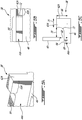
- FIGS. 5A, 5B and 5C depict a perspective view, top view and front view, respectively of a portion of the tooth 44A of FIG. 4A proximal axial edge 62A of tooth 44A.
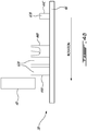
- FIG. 5C further illustrates sensor 40 disposed in relation to axial edge 62A of tooth 44A when tooth 44A is being detected by sensor 40 as phonic wheel 38 rotates about rotation axis R (shown in FIG. 2 ).
- First axial end 63A may be raised and have a greater height 66 from the annular body 46 than a height 69 of mid portion 64 from the annular body 46.
- mid portion 64 may have a substantially axially uniform height from the annular body 46.
- a progressive transition 72 may be defined between first axial end 63A and mid portion 64. In some embodiments, progressive transition 72 may be rounded. As depicted in FIG. 5C , transition 72 may be a fillet between mid portion 64 and first axial end 63A.
- first axial end 63A and second axial end 63B may both be raised and both have a height 66 from annular body 46 that is greater than height 69 of mid portion 64 from annular body 46.
- height 66 may be about 1.1 time the height 69.
- height 66 may be greater than 1.1 time the height 69.
- height 66 may be between 1.1 and two times the height 69.
- height 66 may be about two times the height 69.
- First axial end 63A and second axial end 63B may have substantially the same or different heights 66 from annular body 46.
- This tooth configuration may be desirable when additional flux guiding capacity (without excessive axial length) is desirable at both axial ends 63A, 63B of a same tooth 44.
- second axial end 63B may not be raised and may have a height 66 from the annular body 46 that is substantially the same as height 69 of mid portion 64 from annular body 46.
- This tooth configuration may be desirable when additional flux guiding capacity (without excessive axial length) is desirable only at one axial end 63A of tooth 44.
- Sensor 40 is located at an axial distance 70 from first axial end 63A and at a height 68 from the annular body 46. In some situations, it may be desirable to have sensor 40 at a height 68 that is between height 69 of the mid portion 64 and height 66 of the first axial end 63A during use. In some situations, such positioning of sensor 40 may benefit from the additional flux guiding capacity provided by raised axial end 63A and promote an accurate detection of tooth 44A by sensor 40 as phonic wheel 38 is rotated. First axial end 63A may have an axially extending length 75.
- FIG. 6A is a front elevation view of another exemplary tooth 144 having a chamfered transition 73 between raised end portions 163A, 163B and mid portion 164. It is understood that tooth 144 may have only one raised end portion 163A or 163B and accordingly only one transition 73.
- FIG. 6B is a front elevation view of another exemplary tooth 244 having a step between raised end portions 263A, 263B and mid portion 264. It is understood that tooth 244 may have only one raised end portion 263A or 263B.
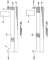
- FIGS. 7A is a cross-sectional view of sensor 40 proximal axial edge 62A of tooth 44C of FIG. 4A that generates a magnetic field that intersects tooth 44C.
- FIG. 7B is a cross-sectional view of sensor 40 proximal axial edge 62A of tooth 44A of FIG. 4A that generates a magnetic field that intersects tooth 44A.
- a tooth such as the tooth 44C may be accurately detected by sensor 40.
- the return path for the magnetic flux has a substantially symmetrical permeability across sensor axis SA provided by sufficient amounts of material (e.g., ferrous metal) from tooth 44C being located on each side of sensor 40.
- edge-related effect may result in asymmetric permeability and skewing of the magnetic field.
- the non-uniformity of the magnetic field may be due to an uneven distribution of material (e.g., ferrous metal) on each side of sensor 40.
- the magnetic flux density on each side of sensor 40 may be different when sensor 40 is located proximal axial edge 62A of tooth 44C.
- the side most proximal to axial edge 62A may have a lower magnetic flux density due to an increased presence of air and a reduced presence of material in comparison to a mid portion 64 of tooth 44C for example.
- the skewing of the magnetic field exhibited with sensor 40 is schematically illustrated in FIG. 7A by line M being offset from sensor axis SA and by the asymmetry of magnetic flux 74 and 76.
- Such edge-related effect exhibited in the magnetic field may cause some error with sensor signals 50 produced by coils 56A and 56B.
- errors can include some error(s) in the determined axial position of phonic wheel 38 and/or some discrepancies between supposedly redundant sensor signals 50 obtained from separate coils 56A and 56B of different channels.
- additional length of teeth 44 may be required beyond each end of the axial travel of phonic wheel 38 relative to sensor 40 in order to avoid potential errors from such edge effects.
- sensor 40 is positioned near axial edge 62A of tooth 44A.
- Raised axial end 63A proximal axial edge 62A provides highly-permeable magnetic return path(s) that may promote symmetry across sensor axis SA.
- Axial end 63A may substantially eliminate edge-related effects otherwise exhibited in a magnetic field using a tooth without a raised axial end.
- Axial end 63A of tooth 44A may provide additional material near the axial edge 62A in comparison to tooth 44C that has a uniform height. Tooth 44A having axial end 63A may have a substantially equal distribution of material on each side of sensor 40 that is detectable by sensor 40.
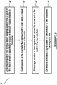
- FIG. 8 is a flowchart illustrating an exemplary method 78 for providing a feedback signal using a phonic wheel.
- Method 78 can be performed using the phonic wheel 38 described herein or other phonic wheels. It is understood that aspects of method 78 can be combined with aspects of other methods described herein.
- method 78 includes: directing a magnetic field from sensor 40 toward a location that tooth 44 of phonic wheel 38 is expected to occupy as tooth 44 rotates relative to sensor 40, the magnetic field including magnetic flux intersecting the location that the rotating tooth 40 is expected to occupy, tooth 44 having first axial end 63A relative to rotation axis R of tooth 44, second axial end 63B opposite first axial end 63A, and mid portion 64 extending between first and second axial ends 63A, 63B, mid portion 64 having a substantially axially uniform height 69, first axial end 63A having a greater height 66 than height 69 of mid portion 64 (see block 80); and using first axial end 63A of tooth 44 to guide some of the magnetic flux intersecting tooth 44 (see block 82); detecting a variation in the magnetic field caused by movement of tooth 44 in the magnetic field (see block 84); and generating a feedback signal based on the detection of the variation in the magnetic field (see block 86).
- sensor 40 is positioned between height 69 of mid portion 64 of tooth 44 and height 66 of first axial end 63A of tooth 44 to promote an accurate detection of a variation in the magnetic field caused by movement of tooth 44.
- tooth 44 includes progressive transition 72 or 73 between mid portion 64 and first axial end 63A to guide some of the magnetic flux intersecting tooth 44 to promote an accurate detection of a variation in the magnetic field caused by movement of tooth 44.
Landscapes
- Engineering & Computer Science (AREA)
- Aviation & Aerospace Engineering (AREA)
- Mechanical Engineering (AREA)
- General Engineering & Computer Science (AREA)
- Physics & Mathematics (AREA)
- General Physics & Mathematics (AREA)
- Transmission And Conversion Of Sensor Element Output (AREA)
- Measurement Of Length, Angles, Or The Like Using Electric Or Magnetic Means (AREA)
Applications Claiming Priority (1)
| Application Number | Priority Date | Filing Date | Title |
|---|---|---|---|
| US16/658,691 US11505307B2 (en) | 2019-10-21 | 2019-10-21 | Phonic wheel and related system and method |
Publications (2)
| Publication Number | Publication Date |
|---|---|
| EP3812264A1 true EP3812264A1 (fr) | 2021-04-28 |
| EP3812264B1 EP3812264B1 (fr) | 2022-08-31 |
Family
ID=73005450
Family Applications (1)
| Application Number | Title | Priority Date | Filing Date |
|---|---|---|---|
| EP20203120.9A Active EP3812264B1 (fr) | 2019-10-21 | 2020-10-21 | Roue phonique et système et procédé correspondants |
Country Status (2)
| Country | Link |
|---|---|
| US (1) | US11505307B2 (fr) |
| EP (1) | EP3812264B1 (fr) |
Families Citing this family (3)
| Publication number | Priority date | Publication date | Assignee | Title |
|---|---|---|---|---|
| US11428116B2 (en) | 2019-11-29 | 2022-08-30 | Pratt & Whitney Canada Corp. | System and method for measuring an axial position of a rotating component of an engine |
| CN115355868B (zh) * | 2022-07-27 | 2024-08-09 | 成都飞机工业(集团)有限责任公司 | 测试飞机发动机轴线对中性的装置及其安装、测试方法 |
| US12391362B2 (en) * | 2023-04-18 | 2025-08-19 | Pratt & Whitney Canada Corp. | System and method for measuring an axial position of a rotating component |
Citations (6)
| Publication number | Priority date | Publication date | Assignee | Title |
|---|---|---|---|---|
| DE3411773A1 (de) * | 1984-03-30 | 1985-05-23 | Daimler-Benz Ag, 7000 Stuttgart | Vorrichtung zur erfassung der drehzahl und/oder eines drehwinkels einer welle |
| WO1989007058A1 (fr) * | 1988-02-08 | 1989-08-10 | Zahnradfabrik Friedrichshafen Ag | Vehicule a essieu directeur mene |
| EP1876422A1 (fr) * | 2006-07-05 | 2008-01-09 | Carl Freudenberg KG | Dispositif destiné à la saisie de mouvements rotatifs et translatoires |
| EP2431715A1 (fr) * | 2009-05-13 | 2012-03-21 | Industria de Turbo Propulsores S.A. | Système de mesure de position axiale |
| US20150139798A1 (en) | 2013-11-21 | 2015-05-21 | Pratt & Whitney Canada Corp. | System and method for electronic propeller blade angle position feedback |
| US20180304991A1 (en) | 2017-04-24 | 2018-10-25 | Pratt & Whitney Canada Corp. | Feedback system for pitch-adjustable blades of aircraft bladed rotor |
Family Cites Families (11)
| Publication number | Priority date | Publication date | Assignee | Title |
|---|---|---|---|---|
| GB8706905D0 (en) * | 1987-03-24 | 1987-04-29 | Schlumberger Electronics Uk | Shaft monitoring system |
| GB2221306A (en) | 1988-07-29 | 1990-01-31 | Dowty Rotol Ltd | Assembly for determining the longitudinal displacement of a rotating shaft |
| US4934901A (en) | 1989-04-21 | 1990-06-19 | Duchesneau Jerome G | Pitch change actuation system |
| US5913659A (en) | 1993-11-22 | 1999-06-22 | United Technologies Corporation | Apparatus and method for adjusting rotor blade tracking |
| US5897293A (en) | 1996-11-22 | 1999-04-27 | United Technologies Corporation | Counterweighted propeller control system |
| US6077040A (en) | 1998-05-01 | 2000-06-20 | United Technologies Corporation | Control system for blades for a variable pitch propeller |
| US6232770B1 (en) * | 1999-07-01 | 2001-05-15 | Delphi Technologies, Inc. | Low cost single magnetoresistor position and speed sensor |
| US6291989B1 (en) * | 1999-08-12 | 2001-09-18 | Delphi Technologies, Inc. | Differential magnetic position sensor with adaptive matching for detecting angular position of a toothed target wheel |
| US6650110B2 (en) * | 2001-06-04 | 2003-11-18 | Delphi Technologies, Inc. | Target wheel sensor assembly for producing an asymmetric signal and for determining the direction of motion of the target wheel based on the signal shape |
| US8687206B2 (en) | 2012-05-29 | 2014-04-01 | United Technologies Corporation | Optical detection of airfoil axial position with NSMS |
| US20140007591A1 (en) | 2012-07-03 | 2014-01-09 | Alexander I. Khibnik | Advanced tip-timing measurement blade mode identification |
-
2019
- 2019-10-21 US US16/658,691 patent/US11505307B2/en active Active
-
2020
- 2020-10-21 EP EP20203120.9A patent/EP3812264B1/fr active Active
Patent Citations (8)
| Publication number | Priority date | Publication date | Assignee | Title |
|---|---|---|---|---|
| DE3411773A1 (de) * | 1984-03-30 | 1985-05-23 | Daimler-Benz Ag, 7000 Stuttgart | Vorrichtung zur erfassung der drehzahl und/oder eines drehwinkels einer welle |
| WO1989007058A1 (fr) * | 1988-02-08 | 1989-08-10 | Zahnradfabrik Friedrichshafen Ag | Vehicule a essieu directeur mene |
| EP1876422A1 (fr) * | 2006-07-05 | 2008-01-09 | Carl Freudenberg KG | Dispositif destiné à la saisie de mouvements rotatifs et translatoires |
| EP2431715A1 (fr) * | 2009-05-13 | 2012-03-21 | Industria de Turbo Propulsores S.A. | Système de mesure de position axiale |
| US20150139798A1 (en) | 2013-11-21 | 2015-05-21 | Pratt & Whitney Canada Corp. | System and method for electronic propeller blade angle position feedback |
| EP2876046A1 (fr) * | 2013-11-21 | 2015-05-27 | Pratt & Whitney Canada Corp. | Système et procédé de rétroaction de position d'angle de pale d'hélice |
| US20180304991A1 (en) | 2017-04-24 | 2018-10-25 | Pratt & Whitney Canada Corp. | Feedback system for pitch-adjustable blades of aircraft bladed rotor |
| EP3396304A1 (fr) * | 2017-04-24 | 2018-10-31 | Pratt & Whitney Canada Corp. | Système de rétroaction pour pales à pas réglable d'un rotor à aube d'un aéronef |
Also Published As
| Publication number | Publication date |
|---|---|
| US20210114716A1 (en) | 2021-04-22 |
| EP3812264B1 (fr) | 2022-08-31 |
| US11505307B2 (en) | 2022-11-22 |
Similar Documents
| Publication | Publication Date | Title |
|---|---|---|
| EP3396304B1 (fr) | Système de rétroaction pour pales à pas réglable d'un rotor à aube d'un aéronef | |
| US9821901B2 (en) | System and method for electronic propeller blade angle position feedback | |
| EP3812264B1 (fr) | Roue phonique et système et procédé correspondants | |
| EP3730902B1 (fr) | Système de rétroaction de position angulaire de pale ayant des capteurs décalés | |
| EP3838745B1 (fr) | Système et procédé de détermination de la position axiale d'un dispositif de rétroaction | |
| US20250346347A1 (en) | System and method for measuring an axial position of a rotating component | |
| EP3831711B1 (fr) | Dispositif de détection de l'angle d'inclinaison des pales à perméabilité magnétique variable | |
| EP3712057B1 (fr) | Système de rétroaction de position angulaire de pale avec marqueurs étendus | |
| US20220089273A1 (en) | Pitch control assembly for an aircraft-bladed rotor | |
| US11623735B2 (en) | Blade angle position feedback system with magnetic shield | |
| EP3722204B1 (fr) | Système de détermination de la position angulaire de pale avec des extrémités de capteur profilées | |
| CA3077916A1 (fr) | Systeme de retroaction de position d`angle de pale avec terminaisons de marqueurs profiles |
Legal Events
| Date | Code | Title | Description |
|---|---|---|---|
| PUAI | Public reference made under article 153(3) epc to a published international application that has entered the european phase |
Free format text: ORIGINAL CODE: 0009012 |
|
| STAA | Information on the status of an ep patent application or granted ep patent |
Free format text: STATUS: THE APPLICATION HAS BEEN PUBLISHED |
|
| AK | Designated contracting states |
Kind code of ref document: A1 Designated state(s): AL AT BE BG CH CY CZ DE DK EE ES FI FR GB GR HR HU IE IS IT LI LT LU LV MC MK MT NL NO PL PT RO RS SE SI SK SM TR |
|
| AX | Request for extension of the european patent |
Extension state: BA ME |
|
| STAA | Information on the status of an ep patent application or granted ep patent |
Free format text: STATUS: REQUEST FOR EXAMINATION WAS MADE |
|
| 17P | Request for examination filed |
Effective date: 20211027 |
|
| RBV | Designated contracting states (corrected) |
Designated state(s): AL AT BE BG CH CY CZ DE DK EE ES FI FR GB GR HR HU IE IS IT LI LT LU LV MC MK MT NL NO PL PT RO RS SE SI SK SM TR |
|
| GRAP | Despatch of communication of intention to grant a patent |
Free format text: ORIGINAL CODE: EPIDOSNIGR1 |
|
| STAA | Information on the status of an ep patent application or granted ep patent |
Free format text: STATUS: GRANT OF PATENT IS INTENDED |
|
| INTG | Intention to grant announced |
Effective date: 20220311 |
|
| GRAS | Grant fee paid |
Free format text: ORIGINAL CODE: EPIDOSNIGR3 |
|
| GRAA | (expected) grant |
Free format text: ORIGINAL CODE: 0009210 |
|
| STAA | Information on the status of an ep patent application or granted ep patent |
Free format text: STATUS: THE PATENT HAS BEEN GRANTED |
|
| AK | Designated contracting states |
Kind code of ref document: B1 Designated state(s): AL AT BE BG CH CY CZ DE DK EE ES FI FR GB GR HR HU IE IS IT LI LT LU LV MC MK MT NL NO PL PT RO RS SE SI SK SM TR |
|
| REG | Reference to a national code |
Ref country code: CH Ref legal event code: EP Ref country code: GB Ref legal event code: FG4D |
|
| REG | Reference to a national code |
Ref country code: AT Ref legal event code: REF Ref document number: 1515127 Country of ref document: AT Kind code of ref document: T Effective date: 20220915 Ref country code: DE Ref legal event code: R096 Ref document number: 602020004822 Country of ref document: DE |
|
| REG | Reference to a national code |
Ref country code: IE Ref legal event code: FG4D |
|
| REG | Reference to a national code |
Ref country code: LT Ref legal event code: MG9D |
|
| REG | Reference to a national code |
Ref country code: NL Ref legal event code: MP Effective date: 20220831 |
|
| PG25 | Lapsed in a contracting state [announced via postgrant information from national office to epo] |
Ref country code: SE Free format text: LAPSE BECAUSE OF FAILURE TO SUBMIT A TRANSLATION OF THE DESCRIPTION OR TO PAY THE FEE WITHIN THE PRESCRIBED TIME-LIMIT Effective date: 20220831 Ref country code: RS Free format text: LAPSE BECAUSE OF FAILURE TO SUBMIT A TRANSLATION OF THE DESCRIPTION OR TO PAY THE FEE WITHIN THE PRESCRIBED TIME-LIMIT Effective date: 20220831 Ref country code: NO Free format text: LAPSE BECAUSE OF FAILURE TO SUBMIT A TRANSLATION OF THE DESCRIPTION OR TO PAY THE FEE WITHIN THE PRESCRIBED TIME-LIMIT Effective date: 20221130 Ref country code: LV Free format text: LAPSE BECAUSE OF FAILURE TO SUBMIT A TRANSLATION OF THE DESCRIPTION OR TO PAY THE FEE WITHIN THE PRESCRIBED TIME-LIMIT Effective date: 20220831 Ref country code: LT Free format text: LAPSE BECAUSE OF FAILURE TO SUBMIT A TRANSLATION OF THE DESCRIPTION OR TO PAY THE FEE WITHIN THE PRESCRIBED TIME-LIMIT Effective date: 20220831 Ref country code: FI Free format text: LAPSE BECAUSE OF FAILURE TO SUBMIT A TRANSLATION OF THE DESCRIPTION OR TO PAY THE FEE WITHIN THE PRESCRIBED TIME-LIMIT Effective date: 20220831 |
|
| REG | Reference to a national code |
Ref country code: AT Ref legal event code: MK05 Ref document number: 1515127 Country of ref document: AT Kind code of ref document: T Effective date: 20220831 |
|
| PG25 | Lapsed in a contracting state [announced via postgrant information from national office to epo] |
Ref country code: PL Free format text: LAPSE BECAUSE OF FAILURE TO SUBMIT A TRANSLATION OF THE DESCRIPTION OR TO PAY THE FEE WITHIN THE PRESCRIBED TIME-LIMIT Effective date: 20220831 Ref country code: IS Free format text: LAPSE BECAUSE OF FAILURE TO SUBMIT A TRANSLATION OF THE DESCRIPTION OR TO PAY THE FEE WITHIN THE PRESCRIBED TIME-LIMIT Effective date: 20221231 Ref country code: HR Free format text: LAPSE BECAUSE OF FAILURE TO SUBMIT A TRANSLATION OF THE DESCRIPTION OR TO PAY THE FEE WITHIN THE PRESCRIBED TIME-LIMIT Effective date: 20220831 Ref country code: GR Free format text: LAPSE BECAUSE OF FAILURE TO SUBMIT A TRANSLATION OF THE DESCRIPTION OR TO PAY THE FEE WITHIN THE PRESCRIBED TIME-LIMIT Effective date: 20221201 |
|
| PG25 | Lapsed in a contracting state [announced via postgrant information from national office to epo] |
Ref country code: SM Free format text: LAPSE BECAUSE OF FAILURE TO SUBMIT A TRANSLATION OF THE DESCRIPTION OR TO PAY THE FEE WITHIN THE PRESCRIBED TIME-LIMIT Effective date: 20220831 Ref country code: RO Free format text: LAPSE BECAUSE OF FAILURE TO SUBMIT A TRANSLATION OF THE DESCRIPTION OR TO PAY THE FEE WITHIN THE PRESCRIBED TIME-LIMIT Effective date: 20220831 Ref country code: PT Free format text: LAPSE BECAUSE OF FAILURE TO SUBMIT A TRANSLATION OF THE DESCRIPTION OR TO PAY THE FEE WITHIN THE PRESCRIBED TIME-LIMIT Effective date: 20230102 Ref country code: ES Free format text: LAPSE BECAUSE OF FAILURE TO SUBMIT A TRANSLATION OF THE DESCRIPTION OR TO PAY THE FEE WITHIN THE PRESCRIBED TIME-LIMIT Effective date: 20220831 Ref country code: DK Free format text: LAPSE BECAUSE OF FAILURE TO SUBMIT A TRANSLATION OF THE DESCRIPTION OR TO PAY THE FEE WITHIN THE PRESCRIBED TIME-LIMIT Effective date: 20220831 Ref country code: CZ Free format text: LAPSE BECAUSE OF FAILURE TO SUBMIT A TRANSLATION OF THE DESCRIPTION OR TO PAY THE FEE WITHIN THE PRESCRIBED TIME-LIMIT Effective date: 20220831 Ref country code: AT Free format text: LAPSE BECAUSE OF FAILURE TO SUBMIT A TRANSLATION OF THE DESCRIPTION OR TO PAY THE FEE WITHIN THE PRESCRIBED TIME-LIMIT Effective date: 20220831 |
|
| PG25 | Lapsed in a contracting state [announced via postgrant information from national office to epo] |
Ref country code: SK Free format text: LAPSE BECAUSE OF FAILURE TO SUBMIT A TRANSLATION OF THE DESCRIPTION OR TO PAY THE FEE WITHIN THE PRESCRIBED TIME-LIMIT Effective date: 20220831 Ref country code: MC Free format text: LAPSE BECAUSE OF FAILURE TO SUBMIT A TRANSLATION OF THE DESCRIPTION OR TO PAY THE FEE WITHIN THE PRESCRIBED TIME-LIMIT Effective date: 20220831 Ref country code: EE Free format text: LAPSE BECAUSE OF FAILURE TO SUBMIT A TRANSLATION OF THE DESCRIPTION OR TO PAY THE FEE WITHIN THE PRESCRIBED TIME-LIMIT Effective date: 20220831 |
|
| REG | Reference to a national code |
Ref country code: DE Ref legal event code: R097 Ref document number: 602020004822 Country of ref document: DE |
|
| REG | Reference to a national code |
Ref country code: BE Ref legal event code: MM Effective date: 20221031 |
|
| PG25 | Lapsed in a contracting state [announced via postgrant information from national office to epo] |
Ref country code: NL Free format text: LAPSE BECAUSE OF FAILURE TO SUBMIT A TRANSLATION OF THE DESCRIPTION OR TO PAY THE FEE WITHIN THE PRESCRIBED TIME-LIMIT Effective date: 20220831 Ref country code: LU Free format text: LAPSE BECAUSE OF NON-PAYMENT OF DUE FEES Effective date: 20221021 Ref country code: AL Free format text: LAPSE BECAUSE OF FAILURE TO SUBMIT A TRANSLATION OF THE DESCRIPTION OR TO PAY THE FEE WITHIN THE PRESCRIBED TIME-LIMIT Effective date: 20220831 |
|
| PLBE | No opposition filed within time limit |
Free format text: ORIGINAL CODE: 0009261 |
|
| STAA | Information on the status of an ep patent application or granted ep patent |
Free format text: STATUS: NO OPPOSITION FILED WITHIN TIME LIMIT |
|
| P01 | Opt-out of the competence of the unified patent court (upc) registered |
Effective date: 20230530 |
|
| 26N | No opposition filed |
Effective date: 20230601 |
|
| PG25 | Lapsed in a contracting state [announced via postgrant information from national office to epo] |
Ref country code: SI Free format text: LAPSE BECAUSE OF FAILURE TO SUBMIT A TRANSLATION OF THE DESCRIPTION OR TO PAY THE FEE WITHIN THE PRESCRIBED TIME-LIMIT Effective date: 20220831 |
|
| PG25 | Lapsed in a contracting state [announced via postgrant information from national office to epo] |
Ref country code: BE Free format text: LAPSE BECAUSE OF NON-PAYMENT OF DUE FEES Effective date: 20221031 |
|
| PG25 | Lapsed in a contracting state [announced via postgrant information from national office to epo] |
Ref country code: IE Free format text: LAPSE BECAUSE OF NON-PAYMENT OF DUE FEES Effective date: 20221021 |
|
| PG25 | Lapsed in a contracting state [announced via postgrant information from national office to epo] |
Ref country code: CY Free format text: LAPSE BECAUSE OF FAILURE TO SUBMIT A TRANSLATION OF THE DESCRIPTION OR TO PAY THE FEE WITHIN THE PRESCRIBED TIME-LIMIT Effective date: 20220831 |
|
| PG25 | Lapsed in a contracting state [announced via postgrant information from national office to epo] |
Ref country code: MK Free format text: LAPSE BECAUSE OF FAILURE TO SUBMIT A TRANSLATION OF THE DESCRIPTION OR TO PAY THE FEE WITHIN THE PRESCRIBED TIME-LIMIT Effective date: 20220831 Ref country code: IT Free format text: LAPSE BECAUSE OF FAILURE TO SUBMIT A TRANSLATION OF THE DESCRIPTION OR TO PAY THE FEE WITHIN THE PRESCRIBED TIME-LIMIT Effective date: 20220831 |
|
| REG | Reference to a national code |
Ref country code: CH Ref legal event code: PL |
|
| PG25 | Lapsed in a contracting state [announced via postgrant information from national office to epo] |
Ref country code: CH Free format text: LAPSE BECAUSE OF NON-PAYMENT OF DUE FEES Effective date: 20231031 |
|
| PG25 | Lapsed in a contracting state [announced via postgrant information from national office to epo] |
Ref country code: HU Free format text: LAPSE BECAUSE OF FAILURE TO SUBMIT A TRANSLATION OF THE DESCRIPTION OR TO PAY THE FEE WITHIN THE PRESCRIBED TIME-LIMIT; INVALID AB INITIO Effective date: 20201021 Ref country code: CH Free format text: LAPSE BECAUSE OF NON-PAYMENT OF DUE FEES Effective date: 20231031 Ref country code: BG Free format text: LAPSE BECAUSE OF FAILURE TO SUBMIT A TRANSLATION OF THE DESCRIPTION OR TO PAY THE FEE WITHIN THE PRESCRIBED TIME-LIMIT Effective date: 20220831 |
|
| PG25 | Lapsed in a contracting state [announced via postgrant information from national office to epo] |
Ref country code: MT Free format text: LAPSE BECAUSE OF FAILURE TO SUBMIT A TRANSLATION OF THE DESCRIPTION OR TO PAY THE FEE WITHIN THE PRESCRIBED TIME-LIMIT Effective date: 20220831 |
|
| PGFP | Annual fee paid to national office [announced via postgrant information from national office to epo] |
Ref country code: GB Payment date: 20250923 Year of fee payment: 6 |
|
| PGFP | Annual fee paid to national office [announced via postgrant information from national office to epo] |
Ref country code: FR Payment date: 20250924 Year of fee payment: 6 |
|
| PG25 | Lapsed in a contracting state [announced via postgrant information from national office to epo] |
Ref country code: TR Free format text: LAPSE BECAUSE OF FAILURE TO SUBMIT A TRANSLATION OF THE DESCRIPTION OR TO PAY THE FEE WITHIN THE PRESCRIBED TIME-LIMIT Effective date: 20220831 |
|
| PGFP | Annual fee paid to national office [announced via postgrant information from national office to epo] |
Ref country code: DE Payment date: 20250923 Year of fee payment: 6 |