EP3812681B1 - Échangeur de chaleur à plaques comportant des plaques d'extrémité - Google Patents
Échangeur de chaleur à plaques comportant des plaques d'extrémité Download PDFInfo
- Publication number
- EP3812681B1 EP3812681B1 EP20200578.1A EP20200578A EP3812681B1 EP 3812681 B1 EP3812681 B1 EP 3812681B1 EP 20200578 A EP20200578 A EP 20200578A EP 3812681 B1 EP3812681 B1 EP 3812681B1
- Authority
- EP
- European Patent Office
- Prior art keywords
- plate
- heat transfer
- heat exchanger
- stack
- end plate
- Prior art date
- Legal status (The legal status is an assumption and is not a legal conclusion. Google has not performed a legal analysis and makes no representation as to the accuracy of the status listed.)
- Active
Links
Images


Classifications
-
- F—MECHANICAL ENGINEERING; LIGHTING; HEATING; WEAPONS; BLASTING
- F28—HEAT EXCHANGE IN GENERAL
- F28D—HEAT-EXCHANGE APPARATUS, NOT PROVIDED FOR IN ANOTHER SUBCLASS, IN WHICH THE HEAT-EXCHANGE MEDIA DO NOT COME INTO DIRECT CONTACT
- F28D9/00—Heat-exchange apparatus having stationary plate-like or laminated conduit assemblies for both heat-exchange media, the media being in contact with different sides of a conduit wall
- F28D9/0031—Heat-exchange apparatus having stationary plate-like or laminated conduit assemblies for both heat-exchange media, the media being in contact with different sides of a conduit wall the conduits for one heat-exchange medium being formed by paired plates touching each other
- F28D9/0043—Heat-exchange apparatus having stationary plate-like or laminated conduit assemblies for both heat-exchange media, the media being in contact with different sides of a conduit wall the conduits for one heat-exchange medium being formed by paired plates touching each other the plates having openings therein for circulation of at least one heat-exchange medium from one conduit to another
- F28D9/005—Heat-exchange apparatus having stationary plate-like or laminated conduit assemblies for both heat-exchange media, the media being in contact with different sides of a conduit wall the conduits for one heat-exchange medium being formed by paired plates touching each other the plates having openings therein for circulation of at least one heat-exchange medium from one conduit to another the plates having openings therein for both heat-exchange media
-
- F—MECHANICAL ENGINEERING; LIGHTING; HEATING; WEAPONS; BLASTING
- F28—HEAT EXCHANGE IN GENERAL
- F28F—DETAILS OF HEAT-EXCHANGE AND HEAT-TRANSFER APPARATUS, OF GENERAL APPLICATION
- F28F3/00—Plate-like or laminated elements; Assemblies of plate-like or laminated elements
- F28F3/08—Elements constructed for building-up into stacks, e.g. capable of being taken apart for cleaning
-
- F—MECHANICAL ENGINEERING; LIGHTING; HEATING; WEAPONS; BLASTING
- F28—HEAT EXCHANGE IN GENERAL
- F28F—DETAILS OF HEAT-EXCHANGE AND HEAT-TRANSFER APPARATUS, OF GENERAL APPLICATION
- F28F2225/00—Reinforcing means
- F28F2225/04—Reinforcing means for conduits
-
- F—MECHANICAL ENGINEERING; LIGHTING; HEATING; WEAPONS; BLASTING
- F28—HEAT EXCHANGE IN GENERAL
- F28F—DETAILS OF HEAT-EXCHANGE AND HEAT-TRANSFER APPARATUS, OF GENERAL APPLICATION
- F28F2265/00—Safety or protection arrangements; Arrangements for preventing malfunction
- F28F2265/16—Safety or protection arrangements; Arrangements for preventing malfunction for preventing leakage
-
- F—MECHANICAL ENGINEERING; LIGHTING; HEATING; WEAPONS; BLASTING
- F28—HEAT EXCHANGE IN GENERAL
- F28F—DETAILS OF HEAT-EXCHANGE AND HEAT-TRANSFER APPARATUS, OF GENERAL APPLICATION
- F28F2275/00—Fastening; Joining
- F28F2275/04—Fastening; Joining by brazing
-
- F—MECHANICAL ENGINEERING; LIGHTING; HEATING; WEAPONS; BLASTING
- F28—HEAT EXCHANGE IN GENERAL
- F28F—DETAILS OF HEAT-EXCHANGE AND HEAT-TRANSFER APPARATUS, OF GENERAL APPLICATION
- F28F2275/00—Fastening; Joining
- F28F2275/06—Fastening; Joining by welding
Definitions
- a typical construction of a plate heat exchanger comprises a plurality of heat transfer plate stacked on top of each other.
- the heat transfer plates are formed with patterns such that flow paths are formed between each set of neighboring heat transfer plates. Openings and are formed in the heat transfer plates to form inlets and outlets for fluids to these flow paths.
- the plates are positioned between end plates, which end plates to same material and weight often are relatively thin, e.g. of the same thickness as the heat transfer plates, or only slightly thicker.
- the heat transfer plates are brazed or welded together at the connections, just as respectively the upper and lower heat transfer plates are brazed or connected to the respective upper and lower end plate.
- WO 97/15798 discloses a plate heat exchanger, where a first end plate is connected to a stack first side outermost heat transfer plate of a stack of heat transfer plates, and a second end plate is connected to the stack second side outermost heat transfer plate, where with a blank area aligned with the first inlet where the second side outermost heat transfer plate is formed with a contacting projection connected and brazed or welded the inner surface of the second end plate.
- the pressures are high, and due to the relatively thin thickness the end-plates tend to deform at high pressures, possible breaking or breaking in the connection to the neighboring heat transfer plates, possible leading to leaks.
- the present invention is aimed to reducing assembly complexity of the typical plate heat exchanger and at the same time improving the mechanical strength by reducing level of deformations on the area around the openings/portholes at the second end plate.
- a plate heat exchanger including a stack of patterned heat transfer plates connected to each other by brazing or welding and defining a first side and second side, were patterns of the connected neighbouring heat transfer plates forms respectively a first flow path and second flow path on the opposing sides of a heat transfer plate, said heat transfer plates comprising aligned first pair of port holes forming respectively first inlet and first outlet for a first fluid to be distributed to said first flow path, where a first end plate is connected to the stack first side outermost heat transfer plate with a first opening aligned to the first inlet, and a second end plate is connected to the stack second side outermost heat transfer plate with a blank area aligned with the first inlet, where the second side outermost heat transfer plate is formed with a contacting projection connected and brazed or welded the inner surface of the second end plate.
- the blank area is curving in an outwards direction relative to the stack and may be dome shaped.
- the second side outermost heat transfer plate is formed as a blank section where aligned with the second end plate blank area, and is curving in an outwards direction relative to the stack and connected by brazing or welding to the inner surface of the blank section of said second end plate, where the second side outermost heat transfer plate blank section may be dome shaped.
- heat transfer plate blank section projects outwards relative to the stack and has a flat top surface connected by brazing or welding to the blank area.
- the heat transfer plate blank section projects outwards relative to the stack and has a flat top surface connected by brazing or welding to the circumference of the blank area.
- a projection is formed as a circular projection contacting the second end plate at an area encircling the blank area.
- the projection has a rounded top surface.
- the projection has a flat top surface.
- Fig. 1 is a side view illustrates a typical plate heat exchanger (100) including a stack (110) of patterned heat transfer plates (1) connected to each other by brazing or welding.
- a first end plate (10) is connected to the stack (110) first side and a second end plate (11) to the stack (110) second side.
- port connections (50) is connected to the first end plate (10) connecting the flow paths formed between the heat transfer plates (1) in the stack to a heating system fluid flow conduits or pipes.
- two such port connections (50) is shown, and both in the first end plate (10).
- Fig. 2 illustrate the same heat exchanger (100) having 6 heat transfer plates (1, 1a, 1b), though any number would apply, and usually it comprised significantly more heat transfer plates (1) than the illustration.
- the heat transfer plates (1, 1a, 1b) are formed as thin sheets shaped with patterns (5), such as the illustrated chevron shaped corrugations. However, any other form of pattern (5) would also apply. Every second heat transfer plate (1, 1a, 1b) either may formed with different patterns (5), or may simply be rotated relative the other plates, such that the patterns (5) only cross each other forming respectively a first flow path and second flow path on the opposing sides of a heat transfer plate (1, 1a, 1b). The crossed patterns (5) then forms heat transferring regions.
- the heat transfer plates (1, 1a, 1b) and first (10) and second (11) end plates are brazed or welded at the rims to seal the flow paths from the externals, and optionally at some, or all, of the other connection points.
- At least some of the heat transfer plates (1, 1a, 1b) comprises a first pair of openings (20, 21) and a second pair of openings (22, 23) - one of which not visible in the figure.
- the openings (20, 21, 22, 23) are aligned to the corresponding openings of the neighbouring heat transfer plates (1, 1a, 1b) such that the e.g. the aligned first pair of openings (20, 21) forms a first inlet (20a) and first outlet (21a) for the first flow paths respectively (illustrated in fig. 1 ), and the aligned second pair of openings (22, 23) forms a second inlet and second outlet for the first flow paths respectively (not illustrated).
- the first end plate (10) is connected to the first side outermost heat transfer plate (1a) with first connection opening (30) aligned to the first inlet (20a), and a second end plate (11) is connected to the stack (110) second side outermost heat transfer plate (1b) with a blank area (12) aligned with the first inlet (20a).
- the blank area (12) could be shaped relative to the bulk of the second end plate (11) or could simple just be the flat part of the second end plate (11) aligning with the first inlet (20a).
- second openings (31) aligns with the first inlet (21a)
- third openings (32) aligns with second inlet
- fourth opening (33) aligns with second outlet.
- other of the openings other embodiments.
- some of the openings (30, 31, 32, 33) are formed in the second end plate (11), the corresponding blank areas (12) thus being in the first end plate (10).
- the respectively first and second pairs, and first and second inlets and outlets are arranged differently.
- the port connections (50) are connected to the first end plate (10) (respectively second end plate (11)) and the openings (30, 31, 32, 33).
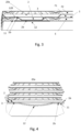
- Fig. 3 illustrate a first reinforcement configuration relevant to the present invention, showing the area around the first inlet (20a) in the area of the second side outermost heat transfer plate (1b) and second end plate (11).
- second side outermost heat transfer plate (1b) is formed with a blank section (2), meaning it does not form any opening (20).
- the blank section (2) forms a flat top surface (2b) of a projection (3) formed in the second side outermost heat transfer plate (1b) in an outwards direction relative to the stack (110), where said flat top surface (2b) is connected by brazing or welding to the blank area (12) of the second end plate (11), which is seen to be flat.
- a sealing area (120) is illustrated between the second side outermost heat transfer plate (1b) and its neighbouring plate (1) in the inlet area (20a).
- the first flow path F1 and second flow path F2 is illustrated between neighbouring heat transfer plates (1, 1b), but the area E between the inner surface of the second end plate (11) and outer surface of the second outer most heat transfer plate (1b) is empty.
- Fig. 4 is a similar illustration to fig. 3 , showing a second reinforcement embodiment, where the blank area (12) is curving in an outwards direction relative to the stack (110).
- the projection (3) is formed as in the embodiment of fig. 3 , only such that it's top surface (2b) is larger than the curvy blank area (12), thus being connected to its circumference. The rest of the flat top surface (2b) thus 'covering' the blank area (12) in the plane of the bulk of the second end plate (11).
- the curvy blank area (12) is dome shaped.
- Fig. 5 is a similar illustration to fig. 4 , showing a third reinforcement embodiment, where the projection (3) in a circular shape with a top surface (2b) with a diameter which is larger than the curvy blank area (12), thus being connected the second end plate (11) in an area encircling the blank area (12).
- Fig. 6 is a fourth reinforcement embodiment similar to illustrations of figs. 4 and 5 , with a curvy or dome shaped blank area (12), but where the projection (3) has curvy shape with a top surface (2b) curving in an outwards direction relative to the stack (110) and connected by brazing or welding to the second end plate (11) blank area (12).
Landscapes
- Engineering & Computer Science (AREA)
- Physics & Mathematics (AREA)
- Thermal Sciences (AREA)
- Mechanical Engineering (AREA)
- General Engineering & Computer Science (AREA)
- Heat-Exchange Devices With Radiators And Conduit Assemblies (AREA)
Claims (9)
- Échangeur de chaleur à plaques (100) comprenant un empilement (110) de plaques de transfert de chaleur (1) à motifs (5) reliées entre elles par brasage ou soudage et définissant un premier côté et un second côté, les motifs (5) des plaques de transfert de chaleur (1) voisines reliées entre elles formant respectivement une première voie d'écoulement et une seconde voie d'écoulement sur les côtés opposés d'une plaque de transfert de chaleur (1), lesdites plaques de transfert de chaleur (1) comprenant une première paire alignée d'orifices (20, 21) formant respectivement une première entrée (20a) et une première sortie (21a) pour un premier fluide à distribuer dans ladite première voie d'écoulement, une première plaque d'extrémité (10) étant reliée à une plaque de transfert de chaleur la plus extérieure de premier côté (1a) de l'empilement (110) avec une première ouverture (30) alignée sur la première entrée (20a), et une seconde plaque d'extrémité (11) étant reliée à une plaque de transfert de chaleur la plus extérieure de second côté (1b) de l'empilement (110) avec une zone vide (12) alignée sur la première entrée (20a), la plaque de transfert de chaleur la plus extérieure de second côté (1b) étant formée d'une saillie de contact (3) reliée et brasée ou soudée à la surface intérieure de la seconde plaque d'extrémité (11), caractérisé en ce que la zone vide (12) est incurvée vers l'extérieur par rapport à l'empilement (110).
- Échangeur de chaleur à plaques (100) selon la revendication 1, la zone vide (12) étant en forme de dôme.
- Échangeur de chaleur à plaques (100) selon la revendication 1 ou 2, la plaque de transfert de chaleur la plus extérieure de second côté (1b) étant formée d'une section vide (2), où elle est alignée avec la zone vide (12) de la seconde plaque d'extrémité (11), et courbée vers l'extérieur par rapport à l'empilement (110) et connectée par brasage ou soudage à la surface intérieure de la zone vide (12) de ladite seconde plaque d'extrémité (11).
- Échangeur de chaleur à plaques (100) selon la revendication 3, la section vide (2) de la plaque de transfert de chaleur la plus extérieure de second côté (1b) étant en forme de dôme.
- Échangeur de chaleur à plaques (100) selon l'une quelconque des revendications 1 et 2, la plaque de transfert de chaleur (1b) étant formée comme une section vide (2) où elle est aligné avec la zone vide (12) de la seconde plaque d'extrémité (11), et ladite section vide (2) faisant saillie vers l'extérieur par rapport à l'empilement (110) et ayant une surface supérieure plate (2a) reliée par brasage ou soudage à la zone vide (12).
- Échangeur de chaleur à plaques (100) selon l'une quelconque des revendications 1 et 2, la plaque de transfert de chaleur (1b) étant formée comme une section vide (2) où elle est alignée avec la zone vide (12) de la seconde plaque d'extrémité (11), ladite section vide (2) faisant saillie vers l'extérieur par rapport à l'empilement (110) et ayant une surface supérieure plate (2a) reliée par brasage ou soudage à la circonférence de la zone vide (12).
- Échangeur de chaleur à plaques (100) selon l'une quelconque des revendications 1 et 2, une saillie (3) étant formée comme une saillie circulaire en contact avec la seconde plaque d'extrémité (11) dans une zone encerclant la zone vide (12).
- Échangeur de chaleur à plaques (100) selon la revendication 7, la saillie (3) ayant une surface supérieure arrondie (2b).
- Échangeur de chaleur à plaques (100) selon la revendication 7, la saillie (3) ayant une surface supérieure plate (2b).
Applications Claiming Priority (1)
| Application Number | Priority Date | Filing Date | Title |
|---|---|---|---|
| DKPA201901252A DK180387B1 (en) | 2019-10-24 | 2019-10-24 | Plate kind heat exchanger with end plates |
Publications (2)
| Publication Number | Publication Date |
|---|---|
| EP3812681A1 EP3812681A1 (fr) | 2021-04-28 |
| EP3812681B1 true EP3812681B1 (fr) | 2023-08-02 |
Family
ID=72801397
Family Applications (1)
| Application Number | Title | Priority Date | Filing Date |
|---|---|---|---|
| EP20200578.1A Active EP3812681B1 (fr) | 2019-10-24 | 2020-10-07 | Échangeur de chaleur à plaques comportant des plaques d'extrémité |
Country Status (4)
| Country | Link |
|---|---|
| EP (1) | EP3812681B1 (fr) |
| DK (2) | DK180387B1 (fr) |
| PL (1) | PL3812681T3 (fr) |
| RU (1) | RU2751676C1 (fr) |
Family Cites Families (10)
| Publication number | Priority date | Publication date | Assignee | Title |
|---|---|---|---|---|
| SE458884B (sv) * | 1987-05-29 | 1989-05-16 | Alfa Laval Thermal Ab | Permanent sammanfogad plattvaermevaexlare med sammanhaallande organ vid portarna |
| SE504868C2 (sv) * | 1995-10-23 | 1997-05-20 | Swep International Ab | Plattvärmeväxlare med ändplatta med pressat mönster |
| TR201809058T4 (tr) * | 2009-06-26 | 2018-07-23 | Swep Int Ab | Asimetrik ısı değiştirici. |
| SE534918C2 (sv) * | 2010-06-24 | 2012-02-14 | Alfa Laval Corp Ab | Värmeväxlarplatta och plattvärmeväxlare |
| RU102252U1 (ru) * | 2010-08-27 | 2011-02-20 | Сергей Васильевич Демин | Пластинчатый теплообменник |
| SE537142C2 (sv) * | 2012-02-14 | 2015-02-17 | Alfa Laval Corp Ab | Plattvärmeväxlare med förbättrad hållfasthet i portområdet |
| JP6192564B2 (ja) * | 2014-02-18 | 2017-09-06 | 日新製鋼株式会社 | プレート式熱交換器およびその製造方法 |
| DE102014203102A1 (de) * | 2014-02-20 | 2015-08-20 | MAHLE Behr GmbH & Co. KG | Plattenwärmetauscher für ein Elektrokraftfahrzeug |
| WO2017072177A1 (fr) * | 2015-10-29 | 2017-05-04 | Danfoss A/S | Protection cathodique d'un échangeur de chaleur |
| CN111006532A (zh) * | 2016-02-04 | 2020-04-14 | 丹佛斯微通道换热器(嘉兴)有限公司 | 板式换热器 |
-
2019
- 2019-10-24 DK DKPA201901252A patent/DK180387B1/en active IP Right Grant
-
2020
- 2020-08-13 RU RU2020127176A patent/RU2751676C1/ru active
- 2020-10-07 DK DK20200578.1T patent/DK3812681T3/da active
- 2020-10-07 EP EP20200578.1A patent/EP3812681B1/fr active Active
- 2020-10-07 PL PL20200578.1T patent/PL3812681T3/pl unknown
Also Published As
| Publication number | Publication date |
|---|---|
| RU2751676C1 (ru) | 2021-07-15 |
| EP3812681A1 (fr) | 2021-04-28 |
| DK180387B1 (en) | 2021-02-26 |
| DK3812681T3 (da) | 2023-11-06 |
| DK201901252A1 (en) | 2021-02-26 |
| PL3812681T3 (pl) | 2024-01-22 |
Similar Documents
| Publication | Publication Date | Title |
|---|---|---|
| EP2257757B2 (fr) | Échangeur de chaleur à plaques | |
| EP2257759B1 (fr) | Échangeur de chaleur à plaques | |
| EP2257756B1 (fr) | Échangeur de chaleur à plaques | |
| EP2394129B1 (fr) | Echangeur thermique a plaques | |
| EP4103904B1 (fr) | Plaque d'échangeur de chaleur et échangeur de chaleur à plaques | |
| KR102109523B1 (ko) | 열교환기 판 및 판 열교환기 | |
| US8887796B2 (en) | Plate heat exchanger | |
| EP3812681B1 (fr) | Échangeur de chaleur à plaques comportant des plaques d'extrémité | |
| WO1994028367A1 (fr) | Echangeur de chaleur | |
| CN111981877B (zh) | 板式热交换器 | |
| EP4001818B1 (fr) | Échangeur de chaleur à plaque et enveloppe et plaque de transfert de chaleur pour échangeur de chaleur à plaque et enveloppe | |
| EP4464971A1 (fr) | Echangeur de chaleur | |
| EP4001822A1 (fr) | Échangeur de chaleur à plaque et enveloppe et plaque de transfert de chaleur pour échangeur de chaleur à plaque et enveloppe |
Legal Events
| Date | Code | Title | Description |
|---|---|---|---|
| PUAI | Public reference made under article 153(3) epc to a published international application that has entered the european phase |
Free format text: ORIGINAL CODE: 0009012 |
|
| STAA | Information on the status of an ep patent application or granted ep patent |
Free format text: STATUS: THE APPLICATION HAS BEEN PUBLISHED |
|
| AK | Designated contracting states |
Kind code of ref document: A1 Designated state(s): AL AT BE BG CH CY CZ DE DK EE ES FI FR GB GR HR HU IE IS IT LI LT LU LV MC MK MT NL NO PL PT RO RS SE SI SK SM TR |
|
| AX | Request for extension of the european patent |
Extension state: BA ME |
|
| STAA | Information on the status of an ep patent application or granted ep patent |
Free format text: STATUS: REQUEST FOR EXAMINATION WAS MADE |
|
| 17P | Request for examination filed |
Effective date: 20210910 |
|
| RBV | Designated contracting states (corrected) |
Designated state(s): AL AT BE BG CH CY CZ DE DK EE ES FI FR GB GR HR HU IE IS IT LI LT LU LV MC MK MT NL NO PL PT RO RS SE SI SK SM TR |
|
| GRAP | Despatch of communication of intention to grant a patent |
Free format text: ORIGINAL CODE: EPIDOSNIGR1 |
|
| STAA | Information on the status of an ep patent application or granted ep patent |
Free format text: STATUS: GRANT OF PATENT IS INTENDED |
|
| INTG | Intention to grant announced |
Effective date: 20230321 |
|
| GRAS | Grant fee paid |
Free format text: ORIGINAL CODE: EPIDOSNIGR3 |
|
| GRAA | (expected) grant |
Free format text: ORIGINAL CODE: 0009210 |
|
| STAA | Information on the status of an ep patent application or granted ep patent |
Free format text: STATUS: THE PATENT HAS BEEN GRANTED |
|
| AK | Designated contracting states |
Kind code of ref document: B1 Designated state(s): AL AT BE BG CH CY CZ DE DK EE ES FI FR GB GR HR HU IE IS IT LI LT LU LV MC MK MT NL NO PL PT RO RS SE SI SK SM TR |
|
| REG | Reference to a national code |
Ref country code: GB Ref legal event code: FG4D |
|
| REG | Reference to a national code |
Ref country code: CH Ref legal event code: EP |
|
| P01 | Opt-out of the competence of the unified patent court (upc) registered |
Effective date: 20230713 |
|
| REG | Reference to a national code |
Ref country code: DE Ref legal event code: R096 Ref document number: 602020014831 Country of ref document: DE |
|
| REG | Reference to a national code |
Ref country code: IE Ref legal event code: FG4D |
|
| REG | Reference to a national code |
Ref country code: NL Ref legal event code: FP |
|
| REG | Reference to a national code |
Ref country code: SE Ref legal event code: TRGR |
|
| REG | Reference to a national code |
Ref country code: DK Ref legal event code: T3 Effective date: 20231101 |
|
| REG | Reference to a national code |
Ref country code: LT Ref legal event code: MG9D |
|
| REG | Reference to a national code |
Ref country code: AT Ref legal event code: MK05 Ref document number: 1595228 Country of ref document: AT Kind code of ref document: T Effective date: 20230802 |
|
| PG25 | Lapsed in a contracting state [announced via postgrant information from national office to epo] |
Ref country code: GR Free format text: LAPSE BECAUSE OF FAILURE TO SUBMIT A TRANSLATION OF THE DESCRIPTION OR TO PAY THE FEE WITHIN THE PRESCRIBED TIME-LIMIT Effective date: 20231103 |
|
| PG25 | Lapsed in a contracting state [announced via postgrant information from national office to epo] |
Ref country code: IS Free format text: LAPSE BECAUSE OF FAILURE TO SUBMIT A TRANSLATION OF THE DESCRIPTION OR TO PAY THE FEE WITHIN THE PRESCRIBED TIME-LIMIT Effective date: 20231202 |
|
| REG | Reference to a national code |
Ref country code: SK Ref legal event code: T3 Ref document number: E 42612 Country of ref document: SK |
|
| PG25 | Lapsed in a contracting state [announced via postgrant information from national office to epo] |
Ref country code: RS Free format text: LAPSE BECAUSE OF FAILURE TO SUBMIT A TRANSLATION OF THE DESCRIPTION OR TO PAY THE FEE WITHIN THE PRESCRIBED TIME-LIMIT Effective date: 20230802 Ref country code: PT Free format text: LAPSE BECAUSE OF FAILURE TO SUBMIT A TRANSLATION OF THE DESCRIPTION OR TO PAY THE FEE WITHIN THE PRESCRIBED TIME-LIMIT Effective date: 20231204 Ref country code: NO Free format text: LAPSE BECAUSE OF FAILURE TO SUBMIT A TRANSLATION OF THE DESCRIPTION OR TO PAY THE FEE WITHIN THE PRESCRIBED TIME-LIMIT Effective date: 20231102 Ref country code: LV Free format text: LAPSE BECAUSE OF FAILURE TO SUBMIT A TRANSLATION OF THE DESCRIPTION OR TO PAY THE FEE WITHIN THE PRESCRIBED TIME-LIMIT Effective date: 20230802 Ref country code: LT Free format text: LAPSE BECAUSE OF FAILURE TO SUBMIT A TRANSLATION OF THE DESCRIPTION OR TO PAY THE FEE WITHIN THE PRESCRIBED TIME-LIMIT Effective date: 20230802 Ref country code: IS Free format text: LAPSE BECAUSE OF FAILURE TO SUBMIT A TRANSLATION OF THE DESCRIPTION OR TO PAY THE FEE WITHIN THE PRESCRIBED TIME-LIMIT Effective date: 20231202 Ref country code: HR Free format text: LAPSE BECAUSE OF FAILURE TO SUBMIT A TRANSLATION OF THE DESCRIPTION OR TO PAY THE FEE WITHIN THE PRESCRIBED TIME-LIMIT Effective date: 20230802 Ref country code: GR Free format text: LAPSE BECAUSE OF FAILURE TO SUBMIT A TRANSLATION OF THE DESCRIPTION OR TO PAY THE FEE WITHIN THE PRESCRIBED TIME-LIMIT Effective date: 20231103 Ref country code: FI Free format text: LAPSE BECAUSE OF FAILURE TO SUBMIT A TRANSLATION OF THE DESCRIPTION OR TO PAY THE FEE WITHIN THE PRESCRIBED TIME-LIMIT Effective date: 20230802 Ref country code: AT Free format text: LAPSE BECAUSE OF FAILURE TO SUBMIT A TRANSLATION OF THE DESCRIPTION OR TO PAY THE FEE WITHIN THE PRESCRIBED TIME-LIMIT Effective date: 20230802 |
|
| PG25 | Lapsed in a contracting state [announced via postgrant information from national office to epo] |
Ref country code: ES Free format text: LAPSE BECAUSE OF FAILURE TO SUBMIT A TRANSLATION OF THE DESCRIPTION OR TO PAY THE FEE WITHIN THE PRESCRIBED TIME-LIMIT Effective date: 20230802 |
|
| PG25 | Lapsed in a contracting state [announced via postgrant information from national office to epo] |
Ref country code: SM Free format text: LAPSE BECAUSE OF FAILURE TO SUBMIT A TRANSLATION OF THE DESCRIPTION OR TO PAY THE FEE WITHIN THE PRESCRIBED TIME-LIMIT Effective date: 20230802 Ref country code: RO Free format text: LAPSE BECAUSE OF FAILURE TO SUBMIT A TRANSLATION OF THE DESCRIPTION OR TO PAY THE FEE WITHIN THE PRESCRIBED TIME-LIMIT Effective date: 20230802 Ref country code: ES Free format text: LAPSE BECAUSE OF FAILURE TO SUBMIT A TRANSLATION OF THE DESCRIPTION OR TO PAY THE FEE WITHIN THE PRESCRIBED TIME-LIMIT Effective date: 20230802 Ref country code: EE Free format text: LAPSE BECAUSE OF FAILURE TO SUBMIT A TRANSLATION OF THE DESCRIPTION OR TO PAY THE FEE WITHIN THE PRESCRIBED TIME-LIMIT Effective date: 20230802 Ref country code: CZ Free format text: LAPSE BECAUSE OF FAILURE TO SUBMIT A TRANSLATION OF THE DESCRIPTION OR TO PAY THE FEE WITHIN THE PRESCRIBED TIME-LIMIT Effective date: 20230802 |
|
| REG | Reference to a national code |
Ref country code: DE Ref legal event code: R097 Ref document number: 602020014831 Country of ref document: DE |
|
| PG25 | Lapsed in a contracting state [announced via postgrant information from national office to epo] |
Ref country code: MC Free format text: LAPSE BECAUSE OF FAILURE TO SUBMIT A TRANSLATION OF THE DESCRIPTION OR TO PAY THE FEE WITHIN THE PRESCRIBED TIME-LIMIT Effective date: 20230802 |
|
| REG | Reference to a national code |
Ref country code: CH Ref legal event code: PL |
|
| PLBE | No opposition filed within time limit |
Free format text: ORIGINAL CODE: 0009261 |
|
| STAA | Information on the status of an ep patent application or granted ep patent |
Free format text: STATUS: NO OPPOSITION FILED WITHIN TIME LIMIT |
|
| REG | Reference to a national code |
Ref country code: BE Ref legal event code: MM Effective date: 20231031 |
|
| PG25 | Lapsed in a contracting state [announced via postgrant information from national office to epo] |
Ref country code: LU Free format text: LAPSE BECAUSE OF NON-PAYMENT OF DUE FEES Effective date: 20231007 |
|
| PG25 | Lapsed in a contracting state [announced via postgrant information from national office to epo] |
Ref country code: LU Free format text: LAPSE BECAUSE OF NON-PAYMENT OF DUE FEES Effective date: 20231007 |
|
| 26N | No opposition filed |
Effective date: 20240503 |
|
| PG25 | Lapsed in a contracting state [announced via postgrant information from national office to epo] |
Ref country code: CH Free format text: LAPSE BECAUSE OF NON-PAYMENT OF DUE FEES Effective date: 20231031 |
|
| PG25 | Lapsed in a contracting state [announced via postgrant information from national office to epo] |
Ref country code: FR Free format text: LAPSE BECAUSE OF NON-PAYMENT OF DUE FEES Effective date: 20231031 Ref country code: CH Free format text: LAPSE BECAUSE OF NON-PAYMENT OF DUE FEES Effective date: 20231031 Ref country code: SI Free format text: LAPSE BECAUSE OF FAILURE TO SUBMIT A TRANSLATION OF THE DESCRIPTION OR TO PAY THE FEE WITHIN THE PRESCRIBED TIME-LIMIT Effective date: 20230802 |
|
| PG25 | Lapsed in a contracting state [announced via postgrant information from national office to epo] |
Ref country code: BE Free format text: LAPSE BECAUSE OF NON-PAYMENT OF DUE FEES Effective date: 20231031 |
|
| PG25 | Lapsed in a contracting state [announced via postgrant information from national office to epo] |
Ref country code: IE Free format text: LAPSE BECAUSE OF NON-PAYMENT OF DUE FEES Effective date: 20231007 |
|
| PG25 | Lapsed in a contracting state [announced via postgrant information from national office to epo] |
Ref country code: IE Free format text: LAPSE BECAUSE OF NON-PAYMENT OF DUE FEES Effective date: 20231007 |
|
| PG25 | Lapsed in a contracting state [announced via postgrant information from national office to epo] |
Ref country code: BG Free format text: LAPSE BECAUSE OF FAILURE TO SUBMIT A TRANSLATION OF THE DESCRIPTION OR TO PAY THE FEE WITHIN THE PRESCRIBED TIME-LIMIT Effective date: 20230802 |
|
| PG25 | Lapsed in a contracting state [announced via postgrant information from national office to epo] |
Ref country code: BG Free format text: LAPSE BECAUSE OF FAILURE TO SUBMIT A TRANSLATION OF THE DESCRIPTION OR TO PAY THE FEE WITHIN THE PRESCRIBED TIME-LIMIT Effective date: 20230802 |
|
| PG25 | Lapsed in a contracting state [announced via postgrant information from national office to epo] |
Ref country code: CY Free format text: LAPSE BECAUSE OF FAILURE TO SUBMIT A TRANSLATION OF THE DESCRIPTION OR TO PAY THE FEE WITHIN THE PRESCRIBED TIME-LIMIT; INVALID AB INITIO Effective date: 20201007 |
|
| PG25 | Lapsed in a contracting state [announced via postgrant information from national office to epo] |
Ref country code: HU Free format text: LAPSE BECAUSE OF FAILURE TO SUBMIT A TRANSLATION OF THE DESCRIPTION OR TO PAY THE FEE WITHIN THE PRESCRIBED TIME-LIMIT; INVALID AB INITIO Effective date: 20201007 |
|
| PGFP | Annual fee paid to national office [announced via postgrant information from national office to epo] |
Ref country code: NL Payment date: 20250912 Year of fee payment: 6 Ref country code: PL Payment date: 20250912 Year of fee payment: 6 Ref country code: IT Payment date: 20250922 Year of fee payment: 6 |
|
| PGFP | Annual fee paid to national office [announced via postgrant information from national office to epo] |
Ref country code: GB Payment date: 20250904 Year of fee payment: 6 |
|
| PGFP | Annual fee paid to national office [announced via postgrant information from national office to epo] |
Ref country code: SE Payment date: 20250910 Year of fee payment: 6 |
|
| PGFP | Annual fee paid to national office [announced via postgrant information from national office to epo] |
Ref country code: SK Payment date: 20250912 Year of fee payment: 6 |
|
| PG25 | Lapsed in a contracting state [announced via postgrant information from national office to epo] |
Ref country code: TR Free format text: LAPSE BECAUSE OF FAILURE TO SUBMIT A TRANSLATION OF THE DESCRIPTION OR TO PAY THE FEE WITHIN THE PRESCRIBED TIME-LIMIT Effective date: 20230802 |
|
| PGFP | Annual fee paid to national office [announced via postgrant information from national office to epo] |
Ref country code: DE Payment date: 20250902 Year of fee payment: 6 |
|
| PGFP | Annual fee paid to national office [announced via postgrant information from national office to epo] |
Ref country code: DK Payment date: 20251014 Year of fee payment: 6 |