EP3812963A2 - Verfahren, gerät, vorrichtung und speichermedium zur fahrzeugidentifikation - Google Patents
Verfahren, gerät, vorrichtung und speichermedium zur fahrzeugidentifikation Download PDFInfo
- Publication number
- EP3812963A2 EP3812963A2 EP21155041.3A EP21155041A EP3812963A2 EP 3812963 A2 EP3812963 A2 EP 3812963A2 EP 21155041 A EP21155041 A EP 21155041A EP 3812963 A2 EP3812963 A2 EP 3812963A2
- Authority
- EP
- European Patent Office
- Prior art keywords
- vehicle
- image
- camera
- feature
- images
- Prior art date
- Legal status (The legal status is an assumption and is not a legal conclusion. Google has not performed a legal analysis and makes no representation as to the accuracy of the status listed.)
- Granted
Links
Images
Classifications
-
- G—PHYSICS
- G06—COMPUTING OR CALCULATING; COUNTING
- G06V—IMAGE OR VIDEO RECOGNITION OR UNDERSTANDING
- G06V20/00—Scenes; Scene-specific elements
- G06V20/20—Scenes; Scene-specific elements in augmented reality scenes
-
- G—PHYSICS
- G08—SIGNALLING
- G08G—TRAFFIC CONTROL SYSTEMS
- G08G1/00—Traffic control systems for road vehicles
- G08G1/01—Detecting movement of traffic to be counted or controlled
- G08G1/017—Detecting movement of traffic to be counted or controlled identifying vehicles
- G08G1/0175—Detecting movement of traffic to be counted or controlled identifying vehicles by photographing vehicles, e.g. when violating traffic rules
-
- G—PHYSICS
- G06—COMPUTING OR CALCULATING; COUNTING
- G06V—IMAGE OR VIDEO RECOGNITION OR UNDERSTANDING
- G06V20/00—Scenes; Scene-specific elements
- G06V20/50—Context or environment of the image
- G06V20/52—Surveillance or monitoring of activities, e.g. for recognising suspicious objects
- G06V20/54—Surveillance or monitoring of activities, e.g. for recognising suspicious objects of traffic, e.g. cars on the road, trains or boats
-
- G—PHYSICS
- G06—COMPUTING OR CALCULATING; COUNTING
- G06F—ELECTRIC DIGITAL DATA PROCESSING
- G06F18/00—Pattern recognition
- G06F18/20—Analysing
- G06F18/21—Design or setup of recognition systems or techniques; Extraction of features in feature space; Blind source separation
- G06F18/214—Generating training patterns; Bootstrap methods, e.g. bagging or boosting
-
- G—PHYSICS
- G06—COMPUTING OR CALCULATING; COUNTING
- G06N—COMPUTING ARRANGEMENTS BASED ON SPECIFIC COMPUTATIONAL MODELS
- G06N3/00—Computing arrangements based on biological models
- G06N3/02—Neural networks
- G06N3/04—Architecture, e.g. interconnection topology
- G06N3/045—Combinations of networks
-
- G—PHYSICS
- G06—COMPUTING OR CALCULATING; COUNTING
- G06N—COMPUTING ARRANGEMENTS BASED ON SPECIFIC COMPUTATIONAL MODELS
- G06N3/00—Computing arrangements based on biological models
- G06N3/02—Neural networks
- G06N3/04—Architecture, e.g. interconnection topology
- G06N3/0464—Convolutional networks [CNN, ConvNet]
-
- G—PHYSICS
- G06—COMPUTING OR CALCULATING; COUNTING
- G06N—COMPUTING ARRANGEMENTS BASED ON SPECIFIC COMPUTATIONAL MODELS
- G06N3/00—Computing arrangements based on biological models
- G06N3/02—Neural networks
- G06N3/08—Learning methods
- G06N3/09—Supervised learning
-
- G—PHYSICS
- G06—COMPUTING OR CALCULATING; COUNTING
- G06T—IMAGE DATA PROCESSING OR GENERATION, IN GENERAL
- G06T7/00—Image analysis
- G06T7/97—Determining parameters from multiple pictures
-
- G—PHYSICS
- G06—COMPUTING OR CALCULATING; COUNTING
- G06V—IMAGE OR VIDEO RECOGNITION OR UNDERSTANDING
- G06V10/00—Arrangements for image or video recognition or understanding
- G06V10/40—Extraction of image or video features
-
- G—PHYSICS
- G06—COMPUTING OR CALCULATING; COUNTING
- G06V—IMAGE OR VIDEO RECOGNITION OR UNDERSTANDING
- G06V10/00—Arrangements for image or video recognition or understanding
- G06V10/70—Arrangements for image or video recognition or understanding using pattern recognition or machine learning
- G06V10/82—Arrangements for image or video recognition or understanding using pattern recognition or machine learning using neural networks
-
- G—PHYSICS
- G06—COMPUTING OR CALCULATING; COUNTING
- G06V—IMAGE OR VIDEO RECOGNITION OR UNDERSTANDING
- G06V20/00—Scenes; Scene-specific elements
- G06V20/10—Terrestrial scenes
- G06V20/176—Urban or other man-made structures
-
- G—PHYSICS
- G06—COMPUTING OR CALCULATING; COUNTING
- G06V—IMAGE OR VIDEO RECOGNITION OR UNDERSTANDING
- G06V20/00—Scenes; Scene-specific elements
- G06V20/50—Context or environment of the image
- G06V20/56—Context or environment of the image exterior to a vehicle by using sensors mounted on the vehicle
-
- G—PHYSICS
- G06—COMPUTING OR CALCULATING; COUNTING
- G06V—IMAGE OR VIDEO RECOGNITION OR UNDERSTANDING
- G06V2201/00—Indexing scheme relating to image or video recognition or understanding
- G06V2201/08—Detecting or categorising vehicles
-
- Y—GENERAL TAGGING OF NEW TECHNOLOGICAL DEVELOPMENTS; GENERAL TAGGING OF CROSS-SECTIONAL TECHNOLOGIES SPANNING OVER SEVERAL SECTIONS OF THE IPC; TECHNICAL SUBJECTS COVERED BY FORMER USPC CROSS-REFERENCE ART COLLECTIONS [XRACs] AND DIGESTS
- Y02—TECHNOLOGIES OR APPLICATIONS FOR MITIGATION OR ADAPTATION AGAINST CLIMATE CHANGE
- Y02T—CLIMATE CHANGE MITIGATION TECHNOLOGIES RELATED TO TRANSPORTATION
- Y02T10/00—Road transport of goods or passengers
- Y02T10/10—Internal combustion engine [ICE] based vehicles
- Y02T10/40—Engine management systems
Definitions
- the embodiments of the present application relate to the field of intelligent search in the field of computer technologies, in particular, to a vehicle re-identification method and apparatus, a device, and a storage medium.
- Vehicle Re-identification (Reid) techniques may be widely applied to the field of vehicle retrieval, vehicle tracking and etc.
- a current method of vehicle re-identification is: after receiving a first image of a first vehicle shot by a first camera, a server extracts a first global feature of the first vehicle, compares the first global feature with a second global feature of a vehicle extracted from a second image on the basis of a vehicle image library, and determines an image of the first vehicle from vehicle images included in the vehicle image library.
- the above method of vehicle re-identification has following problems: if the appearance of two vehicles is very similar, the images of the two vehicles may be misjudged as the image of the same vehicle, that is, the current vehicle re-identification method has a technical issue of low accuracy.
- the present application provides a vehicle re-identification method and apparatus, a device and a storage medium, which improve the accuracy of vehicle re-identification.
- a vehicle re-identification method which includes: receiving a re-identification request from a terminal device, the re-identification request including a first image of a first vehicle shot by a first camera and information of the first camera; acquiring a first feature of the first vehicle and a first head orientation of the first vehicle according to the first image; determining a second image of the first vehicle from images of multiple vehicles according to the first feature, multiple second features extracted based on the images of the multiple vehicles in an image database, the first head orientation of the first vehicle, and the information of the first camera; and transmitting the second image to the terminal device.
- a vehicle re-identification apparatus which includes:
- a vehicle re-identification device including:
- a non-transitory computer-readable storage medium storing computer instructions for causing the computer to execute the method according to the first aspect.
- a computer program product where the program product includes: a computer program, the computer program is stored in a readable storage medium, at least one processor of the electronic device can read the computer program from the readable storage medium, and the at least one processor executes the computer program such that the electronic device executes the method described in the first and second aspects.
- the technology according to the present application improves the accuracy of vehicle re-identification.
- the present application introduces the following elements: if after an image of a vehicle is shot by a camera A, the next camera shooting an image of the vehicle is a camera B, then the camera A and the camera B are adjacent. Or, after an image of a vehicle is shot by a camera B, the next camera shooting an image of the vehicle is a camera A, then the camera A and the camera B are adjacent.
- the embodiments of the present application relate to the fields of computer vision, intelligent search, deep learning, and intelligent transportation in the field of computer technologies to achieve the technical effect of improving the accuracy of vehicle re-identification.
- a current method of vehicle re-identification is: after receiving a first image of a first vehicle shot by a first camera, a server extracts a first global feature of the first vehicle, compares the first global feature with a second global feature of a vehicle extracted from a second image on the basis of a vehicle image library, and determines an image of the first vehicle from vehicle images included in the vehicle image library.
- the above method of vehicle re-identification has following problems: if the appearance of two vehicles is very similar, the images of the two vehicles may be misjudged as the image of the same vehicle, that is, the current vehicle re-identification method has a technical issue of low accuracy.
- the present application introduces information of a camera and a head orientation of a vehicle in an image taken by a camera to improve the accuracy of vehicle re-identification.
- FIG. 1 is a schematic diagram of a system architecture provided by an embodiment of the present application.
- the system architecture includes a server and a terminal device.
- the terminal device transmits a re-identification request to the server.
- the re-identification request includes a first image of a first vehicle shot by a first camera, and information of the first camera; the server acquires a first feature of the first vehicle and a first head orientation of the first vehicle according to the first image; determines a second image of the first vehicle from images of multiple vehicles according to the first feature, multiple second features extracted from the images of the multiple vehicles in an image database, the first head orientation, and the information of the first camera.
- the server transmits the second image to the terminal device. It is understandable that the server may also transmits a shooting time of the second image, information of a camera that took the second image, and the like to the terminal device.
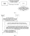
- FIG. 2 is a first flowchart of a vehicle re-identification method provided by an embodiment of the present application.
- the method of the embodiment includes: Step S201, a terminal device transmits a re-identification request to a server, where the re-identification request includes a first image of a first vehicle shot by a first camera and information of the first camera.
- the image after a camera takes an image, the image, a time when the image was taken, and information of the camera are stored in an associated manner.
- the information of the camera includes a geographic location of the camera and a lens orientation of the camera.
- the first image of the first vehicle is stored in association with a shooting time of the first image and the information of the first camera. Therefore, the re-identification request may also include the shooting time of the first image.
- the re-identification request may also include a preset time period.
- the method for acquiring at least one frame of first image of the first vehicle may be as follows: the server acquires at least one frame of image shot by the first camera in a first time period; detects the first vehicle from the at least one frame of image by using a target detection method, to obtain at least one frame of first image of the first vehicle. It is understandable that the shooting time of the first image belongs to (falls into) the first time period.
- Step S202 the server acquires a first feature of the first vehicle and a first head orientation of the first vehicle according to the first image.
- the first image used by the server may be all the first images included in the re-identification request, or may be remaining first images after removing the first images whose resolutions are smaller than the preset resolution.
- the first feature of the first vehicle is at least similar to the appearance of the vehicle, such as a global feature of the vehicle. Therefore, in one solution, the first feature of the first vehicle is the global feature of the first vehicle. In another solution, the first feature of the first vehicle is a feature after fusion of a global sub-feature and a feature point sub-feature of the first vehicle. Where N feature points may be defined, and the feature point sub-feature of the first vehicle includes features of at least part of the feature points of the N feature points of the first vehicle. Where the global feature of the vehicle may include at least one of contour information of the vehicle, color information of the vehicle, and model information of the vehicle.
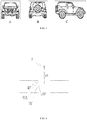
- the head orientation of the first vehicle in the embodiment is acquired according to the head orientation of the first vehicle in the first image. For example, a head orientation of a vehicle in FIG. 3A is downward, a head orientation of a vehicle in FIG. 3B is downward, and a head orientation of a vehicle in FIG. 3C is rightward.
- a head orientation of a vehicle in an image is related to a lens orientation of a camera that took the image and a current driving posture of the vehicle. For example, if the driving posture of the vehicle makes the lens orientation of the camera opposite to the head of the vehicle, the image shot is as shown in FIG. 3A , and the head orientation of the vehicle is downward. If the driving posture of the vehicle makes the lens orientation of the camera on the left side of the vehicle, the image shot is as shown in FIG. 3C , the head orientation of the vehicle is rightward. If the driving posture of the vehicle makes the lens orientation of the camera opposite to the trail of the vehicle, the image shot is as shown in FIG. 3B , and the head orientation of the vehicle is upward.
- Step S203 the server determines a second image of the first vehicle from images of multiple vehicles according to the first feature, multiple second features extracted based on the images of the multiple vehicles in an image database, the first head orientation of the first vehicle, and the information of the first camera.
- the images of the multiple vehicles are images of the vehicles taken by cameras in a preset area within the preset time period.
- the multiple vehicles in the embodiment and multiple second features have a one-to-one correspondence. It may be understood that when a first feature of a first vehicle is a global feature of the first vehicle, a second feature is also a global feature of the vehicle; when the first feature of the first vehicle is a feature after fusion of a global sub-feature and a feature point sub-feature of the first vehicle, the second feature is also a feature after fusion of a global sub-feature and a feature point sub-feature of a corresponding vehicle. And the method for acquiring the first feature is as same as the method for acquiring the second feature.
- the camera may capture at least one frame of image of the vehicle, from the time when the vehicle appears in a shooting range of the camera to the time when the vehicle disappears from the shooting range of the camera.
- the second feature of the vehicle may be acquired based on the at least one frame of image of the vehicle.
- the vehicle re-identification method in the embodiment considers not only a feature of a vehicle, but also a head orientation of the vehicle in an image and information of a camera that shot the image, a predicted head orientation of the vehicle in an image of the vehicle shot by an adjacent camera may be predicted according to the head orientation of the vehicle in the image and the information of the camera that shot the image, so that images shot by the adjacent cameras with similar features but with head orientations different from the predicted head orientation may be filtered out. Therefore, the method of the embodiment may reduce the probability of recognizing the image of a vehicle similar in appearance to the vehicle to be re-identified as the vehicle to be re-identified, and improve the accuracy of vehicle re-identification.
- a vehicle to be re-identified is a vehicle a
- features of a vehicle b are very similar to those of vehicle a
- a head orientation of the vehicle b is a first orientation
- a head orientation of the vehicle a when passing by a camera b is predicted as a second orientation according to a lens orientation of the camera b that shoots the vehicle b, so it may be determined that the vehicle b and the vehicle a are not the same vehicle, that is, the image of the vehicle b will not be determined as the image of the vehicle a shot by the camera b.
- Step S204 the server transmits to the terminal device the second image of the first vehicle determined from the images of the multiple vehicles.
- the server may also transmit to the terminal device the shooting time of the second image and the information of the camera that shot the second image.
- the vehicle re-identification method in the embodiment considers not only a feature of a vehicle, but also a head orientation of the vehicle in an image and information of a corresponding camera, so it may reduce the probability of recognizing the image of the vehicle similar in appearance to the vehicle to be re-identified as the vehicle to be re-identified, and improve the accuracy of vehicle re-identification.
- FIG. 2 The implementation shown in FIG. 2 will be described in detail below with reference to several specific embodiments.
- a first feature of a first vehicle includes a global feature of the first vehicle.
- the acquiring the first feature of the first vehicle according to the first image includes: acquiring, based on the first image, the global feature of the first vehicle by adopting a second neural network model.
- the second neural network model is a pre-trained neural network model for extracting a global feature of a vehicle.
- the first image has at least one frame.
- the acquiring the global feature of the first vehicle includes the following a1-a2:
- the acquiring the global feature of the first vehicle according to the global features of the first vehicle corresponding to the respective first images includes: averaging output vectors obtained by adopting the second neural network model and based on each first image, the obtained vector is thus the global feature of the first vehicle.
- averaging multiple vectors is: adding components at the same positions of respective vectors and then taking the average value.
- This manner is more efficient for acquiring the first feature of the first vehicle.
- the acquiring the first feature of the first vehicle according to the first image includes the following b1-b2:
- the acquiring, based on the first image, a feature point sub-feature of the first vehicle by adopting a third neural network model includes b21-b23:
- the feature point sub-feature of the first vehicle corresponding to the first image is a feature vector
- the feature point sub-feature of the first vehicle is obtained by averaging respective feature vectors.
- the first feature of the first vehicle acquired in this way is more comprehensive, which improves the accuracy of vehicle re-identification.
- This embodiment describes the specific implementation of acquiring the first feature of the first vehicle based on the first image.
- the acquiring the first head orientation of the first vehicle according to the first image includes the following d1-d2:
- the head orientations of the first vehicle in respective first images may include multiple head orientations, and each head orientation corresponds to at least one frame of first image, where an image corresponding to a head orientation means that a head orientation of the vehicle in this image is this head orientation.
- the first head orientation of the first vehicle is a first type head orientation in multiple head orientations, and the first type head orientation corresponds to the largest number of first images.
- the numbers of the first images corresponding to respective head orientations of the multiple head orientations are the same, determining the first head orientation of the first vehicle as a head orientation of the first vehicle in a first image with the latest shooting time or a head orientation randomly selected from the multiple head orientations. If there are at least two head orientations corresponding to the largest number of the first images among the multiple head orientations, one head orientation is randomly selected from the at least two head orientations as the first head orientation of the first vehicle.
- the acquiring the first head orientation of the first vehicle according to the first image includes: acquiring a head orientation of the first vehicle in a first image with the latest shooting time, and determining the head orientation as the first head orientation of the first vehicle.
- This method is more efficient for acquiring the first head orientation of the first vehicle.
- This embodiment describes the specific implementation of the step of acquiring the first head orientation of the first vehicle according to the first image.
- the server determines a second image of the first vehicle from images of multiple vehicles according to the first feature, multiple second features extracted based on the images of the multiple vehicles in an image database, the first head orientation of the first vehicle, and the information of the first camera" will be described by a specific embodiment.
- the server determines a second image of the first vehicle from images of multiple vehicles according to the first feature, multiple second features extracted based on the images of the multiple vehicles in an image database, the first head orientation of the first vehicle, and the information of the first camera" includes the following e1-e2:
- a method for acquiring the head orientation of the pre-selected vehicle is as same as the method for acquiring the first head orientation of the first vehicle. That is, the head orientation of the pre-selected vehicle is obtained based on the image of the pre-selected vehicle.
- the determining the second image of the first vehicle from the images of the pre-selected vehicles includes e21-e23:
- the determining the second image of the first vehicle from the images of the pre-selected vehicles includes e24-e26:
- images of respective pre-selected vehicles include an image 1 of a pre-selected vehicle 1, an image 2 and an image 3 of a pre-selected vehicle 2, an image 4 of a pre-selected vehicle 3, an image 5, an image 6 and an image 7of a pre-selected vehicle 4,
- the image 1 is an image taken by a pre-selected camera 1
- the image 2 and the image 3 are images taken by a pre-selected camera 2
- the image 4 is an image taken by a pre-selected camera 3
- the image 5, the image 6, and the image 7 are images taken by a pre-selected camera 4.
- a target shooting time of the image 1 is earlier than a target shooting time of the first image
- shooting times corresponding to the images 2 to 7 are later than the target shooting time of the first image.
- the target shooting time of the image 1 of the pre-selected vehicle 1 is earlier than the target shooting time of the first image of the first vehicle
- the target shooting time of the first image of the first vehicle is earlier than a target shooting time of the images of the pre-selected vehicle 2
- the target shooting time of the images of the pre-selected vehicle 2 is earlier than a target shooting time of the image of the pre-selected vehicle 3
- the target shooting time of the image of the pre-selected vehicle 3 is earlier than a target shooting time of the images of the pre-selected vehicle 4.
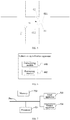
- the specific determination method may be: determining a possible driving direction of the first vehicle based on the first head orientation of the first vehicle, the lens orientation of the first camera, and the geographic location of the first camera. Next, determining whether the first vehicle will appear in the pre-selected camera 2 based on a geographic location of the pre-selected camera 2 and the possible driving direction of the first vehicle. Specifically, as shown in FIG.
- the driving state includes a driving position range and a vehicle posture.
- FIG. 4 shows possible positions of the first vehicle and a posture of the first vehicle, the posture of the vehicle includes: 411 is a head of the first vehicle, and 412 is a trail of the first vehicle.
- the driving state it is determined that the possible driving direction of the first vehicle 41 is a direction 43. If it is determined that the geographic location of the pre-selected camera 2 is a geographic location of a camera that may be reached by the first vehicle traveling in the direction 43, determining that the first vehicle will appear in the pre-selected camera 2.
- the first vehicle will appear in the pre-selected camera 2, predicting, according to the possible driving direction of the first vehicle and the lens orientation of the pre-selected camera 2, a head orientation of the first vehicle in an image of the first vehicle shot by the pre-selected camera 2, that is, acquiring a predicted head orientation of the first vehicle when appearing in the pre-selected camera 2. If the predicted head orientation is as same as the head orientation of the pre-selected vehicle 2, determining that the image 2 and the image 3 of the pre-selected vehicle 2 are the second image of the first vehicle. It is understandable that the head orientation of the pre-selected vehicle 2 is obtained based on the image 2 and the image 3 and by adopting the first neural network model.
- the specific determination method may be: determining a possible driving direction of the pre-selected vehicle 2 based on the head orientation of the pre-selected vehicle 2, the lens orientation of the pre-selected camera 2, and the geographic location of the pre-selected camera 2.
- determining whether the pre-selected vehicle 2 will appear in the pre-selected camera 3 based on the geographic location of the pre-selected camera 3 and the possible driving direction of the pre-selected vehicle 2.
- the pre-selected vehicle 2 will appear in the pre-selected camera 3, predicting, according to the possible driving direction of the pre-selected vehicle 2 and the lens orientation of the pre-selected camera 2, a head orientation of the pre-selected vehicle 2 in an image of the pre-selected vehicle 2 shot by the pre-selected camera 3, that is, acquiring a predicted head orientation of the pre-selected vehicle 2 when appearing in the pre-selected camera 3. If the predicted head orientation is as same as the head orientation of the pre-selected vehicle 3, determining that the image 4 of the pre-selected vehicle 3 is the second image of the first vehicle.
- the pre-selected vehicle 3 will appear in the pre-selected camera 4 according to the head orientation of the pre-selected vehicle 3, the geographic location of the pre-selected camera 3, the lens orientation of the pre-selected camera 3, and a geographic location of the pre-selected camera 4. If it is determined that the pre-selected vehicle 3 will appear in the pre-selected camera 4, predicting, according to the possible driving direction of the pre-selected vehicle 3 and the lens orientation of the pre-selected camera 4, a head orientation of the pre-selected vehicle 3 in an image of the pre-selected vehicle 3 shot by the pre-selected camera 4, that is, acquiring a predicted head orientation of the pre-selected vehicle 3 when appearing in the pre-selected camera 4. If the predicted head orientation is not as same as the head orientation of the pre-selected vehicle 4, determining that the images 5-7 of the pre-selected vehicle 4 are not the second image of the first vehicle.
- the specific determination method may be: determining a possible driving direction towards which the first vehicle can travel to reach a position where the first camera is located, based on the first head orientation of the first vehicle and the lens orientation of the first camera.
- determining whether the first camera will appear in the pre-selected camera 1 based on a geographic location of the pre-selected camera 1 and the possible driving direction towards which the first vehicle can travel to reach a position where the first camera is located. Specifically, as shown in FIG.
- the driving state includes a driving position range and a vehicle posture.
- FIG. 5 shows the position and the posture of the first vehicle, the posture of the vehicle includes: 411 is a head of the first vehicle, and 412 is a trail of the first vehicle.
- the driving state it is determined that the driving direction towards which the first vehicle can travel to reach a position where the first camera is located is 51. If it is determined that the geographic location of the pre-selected camera 1 may be reached by the first vehicle traveling in the direction 51 from the pre-selected camera 1, determining that the first vehicle will appear in the pre-selected camera 1.
- the first vehicle If it is determined that the first vehicle will appear in the pre-selected camera 1, predicting, according to the driving direction towards which the first vehicle can travel to reach a position where the first camera is located, and the lens orientation of the pre-selected camera 1, a head orientation of the first vehicle in an image of the first vehicle shot by the pre-selected camera 1, that is, acquiring a predicted head orientation of the first vehicle when appearing in the pre-selected camera 1. If the predicted head orientation is as same as the head orientation of the pre-selected vehicle 1, determining that the image 1 of the pre-selected vehicle 1 is the second image of the first vehicle. It may be understood that if the image 1 of the pre-selected vehicle 1 is the second image of the first vehicle, the first vehicle first appears in the field of view of the pre-selected camera 1 and then appears in the field of view of the first camera.
- the server determines a second image of the first vehicle from images of multiple vehicles according to the first feature, multiple second features extracted based on the images of the multiple vehicles in an image database, the first head orientation of the first vehicle, and the information of the first camera".
- FIG. 6 is a schematic structural diagram of a vehicle re-identification apparatus provided by an embodiment of the present application.
- the device of the embodiment may include a transceiving module 601 and a processing module 602.
- the transceiving module 601 is configured to receive a re-identification request from a terminal device, the re-identification request includes a first image of a first vehicle shot by a first camera and information of the first camera; the processing module 602 is configured to acquire a first feature of the first vehicle and a first head orientation of the first vehicle according to the first image; the processing module 602 is configured to determine a second image of the first vehicle from images of multiple vehicles according to the first feature, multiple second features extracted based on the images of the multiple vehicles in an image database, the first head orientation of the first vehicle, and the information of the first camera; the transceiving module 601 is further configured to transmit the second image to the terminal device.
- the processing module 602 is specifically configured to: for each frame of first image, acquire a head orientation of the first vehicle in the first image according to the first image, and acquire the first head orientation of the first vehicle according to the head orientations of the first vehicle in respective first images.
- processing module 602 is specifically configured to acquire, based on the first image, the head orientation of the first vehicle in the first image by adopting a first neural network model.
- the processing module 602 is specifically configured to determine images of pre-selected vehicles from the images of the multiple vehicles according to the first feature, the multiple second features extracted based on the images of the multiple vehicles; where a similarity between a second feature extracted based on an image of a pre-selected vehicle and the first feature is greater than or equal to a preset similarity; and determine the second image of the first vehicle from the images of the pre-selected vehicles according to head orientations of the pre-selected vehicles, the first head orientation of the first vehicle, the information of the first camera, and information of a camera for shooting the images of the pre-selected vehicles.
- the re-identification request further includes a shooting time of the first image
- the re-identification request further includes a shooting time of the first image
- the processing module 602 is specifically configured to acquire, based on the first image, the global feature of the first vehicle by adopting a second neural network model.
- the acquiring the first feature of the first vehicle according to the first image includes: acquiring, based on the first image, the global sub-feature of the first vehicle by adopting a second neural network model; acquiring, based on the first image, the feature point sub-feature of the first vehicle by adopting a third neural network model; and fusing the global sub-feature and the feature point sub-feature to obtain the first feature of the first vehicle.
- information of a camera includes a geographic location of the camera and a lens orientation of the camera.
- the apparatus of the embodiment may be configured to implement the technical solutions of the above method embodiments, and its implementation principles and technical effects are similar, and will not be repeated here.
- the present application also provides an electronic device and a readable storage medium.
- FIG. 7 is a block diagram of an electronic device of a vehicle re-identification method according to an embodiment of the present application.
- the electronic device is intended to represent various forms of digital computers, such as laptop computers, desktop computers, workstations, personal digital assistants, servers, blade servers, mainframe computers, and other suitable computers.
- the electronic device may also represent various forms of mobile devices, such as personal digital assistants, cellular phones, smart phones, wearable devices, and other similar computing devices.
- the components shown herein, their connections and relationships, and their functions are merely examples, and are not intended to limit the implementation of the present application described and/or required herein.
- the electronic device includes: one or more processors 701, a memory 702, and interfaces for connecting various components, including high-speed interfaces and low-speed interfaces.
- the various components are connected to each other by different buses, and may be installed on a common motherboard or installed in other ways as needed.
- the processor may process instructions executed in the electronic device, including instructions stored in or on the memory to display graphical information of a GUI on an external input/output apparatus (i.e., a display device coupled to an interface).
- an external input/output apparatus i.e., a display device coupled to an interface.
- multiple processors and/or multiple buses may be used together with multiple memories if necessary.
- multiple electronic devices may be connected, and each device provides some necessary operations (i.e., as a server array, a group of blade servers, or a multi-processor system).
- a processor 701 is taken as an example in FIG. 7 .
- the memory 702 is the non-transitory computer-readable storage medium provided by the present application. Where the memory stores instructions that may be executed by at least one processor, so that the at least one processor executes the vehicle re-identification method provided in the present application.
- the non-transitory computer-readable storage medium of the present application stores computer instructions that cause the computer to execute the vehicle re-identification method provided in the present application.
- the memory 702 may be used for storing non-transitory software programs, non-transitory computer executable programs, and modules, such as program instructions/modules (i.e., the transceiving module 601 and the processing module 602 shown in FIG. 6 ) corresponding to the vehicle re-identification method in the embodiment of the present application.
- the processor 701 executes various functional applications and data processing of the server by running non-transitory software programs, instructions, and modules that are stored in the memory, that is, implements the vehicle re-identification method in the above method embodiments.
- the memory 702 may include a program storage area and a data storage area, where the program storage area may store an operating system and an application program required by at least one function; the data storage area may store data generated by the utilization of the terminal device and/or server.
- the memory 702 may include a high-speed random access memory, or a non-transitory memory, such as at least one magnetic disk storage device, a flash memory device, or other non-transitory solid-state storage devices.
- the memory 702 may optionally include memories remotely located relative to the processor 701, and these remote memories may be connected to the electronic device for vehicle re-identification through a network. Examples of the above networks include, but are not limited to, the Internet, a corporate intranet, a local area network, a mobile communication network and combinations thereof.
- the electronic device for the vehicle re-identification method may further include: an input apparatus 703 and an output apparatus 704.
- the processor 701, the memory 702, the input apparatus 703, and the output apparatus 704 may be connected by a bus or in other ways. In FIG. 7 , the connection by a bus is taken as an example.
- the input apparatus 703 can receive input digital or character information, and generate key signal input related to the user settings and function control of the terminal device and/or server, such as touch screen, a keyboard, a mouse, a trackpad, a touchpad, a command stick, one or more mouse buttons, a trackball, a joystick and other input apparatuses.
- the output apparatus 704 may include a display device, an auxiliary lighting device (such as, LED), a tactile feedback device (such as, a vibration motor), etc.
- the display device may include, but is not limited to, a liquid crystal display (LCD), a light emitting diode (LED) display, and a plasma display. In some embodiments, the display device may be a touch screen.
- Various implementations of the systems and technologies described herein can be implemented in the digital electronic circuit systems, integrated circuit systems, application specific integrated circuits (ASIC), computer hardware, firmware, software, and/or combinations thereof. These various implementations may include: being implemented in one or more computer programs, where the one or more computer programs may be executed and/or interpreted on a programmable system including at least one programmable processor, the programmable processor can be a dedicated or general-purpose programmable processor that can receive data and instructions from the storage system, at least one input apparatus, and at least one output apparatus, and send the data and instructions to the storage system, the at least one input apparatus, and the at least one output apparatus.
- ASIC application specific integrated circuits
- the system and technology described here can be implemented on a computer, where the computer is equipped with: a display apparatus for displaying information to the user (such as, a CRT (cathode ray tube) or LCD (liquid crystal display) monitor); and a keyboard and a guiding apparatus (such as, a mouse or a trackball) through which the user can provide input to the computer.
- a display apparatus for displaying information to the user
- a keyboard and a guiding apparatus such as, a mouse or a trackball
- Other types of apparatuses can also be used for providing interaction with the user; for example, the feedback provided to the user can be any form of sensory feedback (such as, visual feedback, auditory feedback, or tactile feedback); and input from the user can be received in any form (including acoustic input, voice input, or tactile input).
- the systems and technologies described here can be implemented in a computing system (such as, data server) that includes a back-end component, or a computing system (such as, an application server) that includes a middleware component, or a computing system (such as, a user computer with a graphical user interface or a web browser through which the user can interact with the implementation of the system and technology described herein) that includes a front-end component, or a computing system that includes any combination of such background components, middleware components, or front-end components and any combination thereof.
- the components of the system can be connected to each other through digital data communication in any form or medium (e.g., communication network). Examples of communication networks include: a local area network (LAN), a wide area network (WAN), and the Internet.
- the computer system may include a client (on-board terminal) and a cloud server.
- the client and the cloud server are generally far away from each other and usually interact through a communication network.
- the relationship between the client and the cloud server is generated by running computer programs with client-cloud server relationship on the corresponding computers.
- the present application also provides a computer program product including a computer program, the computer program is stored in a readable storage medium, at least one processor of an electronic device can read the computer program from the readable storage medium, and the at least one processor executes the computer program to enable the electronic device to execute the scheme provided by any one of the above embodiments.
- the vehicle re-identification method in the embodiment considers not only a feature of a vehicle, but also a head orientation of the vehicle in an image and information of a camera that shot the image, a predicted head orientation of the vehicle in an image of the vehicle shot by an adjacent camera may be predicted according to the head orientation of the vehicle in the image and the information of the camera that shot the image, so that images shot by the adjacent cameras with similar features but with head orientations different from the predicted head orientation may be filtered out. Therefore, the method of the embodiment may reduce the probability of recognizing the image of a vehicle similar in appearance to the vehicle to be re-identified as the vehicle to be re-identified, and improve the accuracy of vehicle re-identification.
Landscapes
- Engineering & Computer Science (AREA)
- Physics & Mathematics (AREA)
- Theoretical Computer Science (AREA)
- General Physics & Mathematics (AREA)
- Evolutionary Computation (AREA)
- Multimedia (AREA)
- Artificial Intelligence (AREA)
- Health & Medical Sciences (AREA)
- Software Systems (AREA)
- General Health & Medical Sciences (AREA)
- Computing Systems (AREA)
- Data Mining & Analysis (AREA)
- General Engineering & Computer Science (AREA)
- Life Sciences & Earth Sciences (AREA)
- Biomedical Technology (AREA)
- Molecular Biology (AREA)
- Computational Linguistics (AREA)
- Mathematical Physics (AREA)
- Biophysics (AREA)
- Computer Vision & Pattern Recognition (AREA)
- Medical Informatics (AREA)
- Databases & Information Systems (AREA)
- Bioinformatics & Cheminformatics (AREA)
- Bioinformatics & Computational Biology (AREA)
- Evolutionary Biology (AREA)
- Image Analysis (AREA)
- Traffic Control Systems (AREA)
- Signal Processing (AREA)
- Information Retrieval, Db Structures And Fs Structures Therefor (AREA)
Applications Claiming Priority (1)
| Application Number | Priority Date | Filing Date | Title |
|---|---|---|---|
| CN202010613125.7A CN111723768B (zh) | 2020-06-30 | 2020-06-30 | 车辆重识别的方法、装置、设备和存储介质 |
Publications (3)
| Publication Number | Publication Date |
|---|---|
| EP3812963A2 true EP3812963A2 (de) | 2021-04-28 |
| EP3812963A3 EP3812963A3 (de) | 2021-08-04 |
| EP3812963B1 EP3812963B1 (de) | 2023-06-14 |
Family
ID=72570428
Family Applications (1)
| Application Number | Title | Priority Date | Filing Date |
|---|---|---|---|
| EP21155041.3A Active EP3812963B1 (de) | 2020-06-30 | 2021-02-03 | Verfahren, gerät, vorrichtung und speichermedium zur fahrzeugidentifikation |
Country Status (5)
| Country | Link |
|---|---|
| US (1) | US11694436B2 (de) |
| EP (1) | EP3812963B1 (de) |
| JP (1) | JP7268076B2 (de) |
| KR (1) | KR20210037623A (de) |
| CN (1) | CN111723768B (de) |
Cited By (2)
| Publication number | Priority date | Publication date | Assignee | Title |
|---|---|---|---|---|
| CN113569912A (zh) * | 2021-06-28 | 2021-10-29 | 北京百度网讯科技有限公司 | 车辆识别方法、装置、电子设备及存储介质 |
| CN119399727A (zh) * | 2024-09-18 | 2025-02-07 | 北京邮电大学 | 一种基于多任务学习的视角感知车辆再识别方法及系统 |
Families Citing this family (12)
| Publication number | Priority date | Publication date | Assignee | Title |
|---|---|---|---|---|
| CN111629151B (zh) * | 2020-06-12 | 2023-01-24 | 北京字节跳动网络技术有限公司 | 视频合拍方法、装置、电子设备及计算机可读介质 |
| CN112530169A (zh) * | 2020-10-29 | 2021-03-19 | 泰州市出彩网络科技有限公司 | 自适应潮汐车道变换系统 |
| CN112289040B (zh) * | 2020-11-25 | 2022-08-19 | 浙江大华技术股份有限公司 | 一种车辆行驶方向识别的方法、装置及存储介质 |
| CN112990217A (zh) * | 2021-03-24 | 2021-06-18 | 北京百度网讯科技有限公司 | 针对车辆的图像识别方法、装置、电子设备和介质 |
| CN113435333A (zh) * | 2021-06-28 | 2021-09-24 | 深圳市商汤科技有限公司 | 一种数据处理方法、装置、计算机设备和存储介质 |
| EP4459563A3 (de) * | 2021-07-02 | 2025-01-22 | Fujitsu Technology Solutions GmbH | Ki-basierte überwachung von rennstrecken |
| CN113591928B (zh) * | 2021-07-05 | 2024-10-15 | 武汉工程大学 | 基于多视角和卷积注意力模块的车辆重识别方法和系统 |
| US20230298350A1 (en) * | 2022-03-15 | 2023-09-21 | Genetec Inc. | Vehicle identification system |
| CN115631264A (zh) * | 2022-11-07 | 2023-01-20 | 维沃移动通信有限公司 | 显示方法、装置、电子设备和可读存储介质 |
| CN115588239B (zh) * | 2022-11-22 | 2023-04-18 | 浙江莲荷科技有限公司 | 交互行为识别方法、装置、设备及存储介质 |
| CN116129154A (zh) * | 2022-12-06 | 2023-05-16 | 华人运通(上海)自动驾驶科技有限公司 | 图像目标关联方法、计算机设备和存储介质 |
| CN115641559B (zh) * | 2022-12-23 | 2023-06-02 | 深圳佑驾创新科技有限公司 | 一种环视摄像头组的目标匹配方法、装置及存储介质 |
Family Cites Families (10)
| Publication number | Priority date | Publication date | Assignee | Title |
|---|---|---|---|---|
| CN108229468B (zh) * | 2017-06-28 | 2020-02-21 | 北京市商汤科技开发有限公司 | 车辆外观特征识别及车辆检索方法、装置、存储介质、电子设备 |
| CN107610091A (zh) | 2017-07-31 | 2018-01-19 | 阿里巴巴集团控股有限公司 | 车险图像处理方法、装置、服务器及系统 |
| CN107622229B (zh) | 2017-08-29 | 2021-02-02 | 中山大学 | 一种基于融合特征的视频车辆重识别方法与系统 |
| JP2020065200A (ja) | 2018-10-18 | 2020-04-23 | パナソニックi−PROセンシングソリューションズ株式会社 | 車両等検知システムおよび車両等検知方法 |
| JP2019106193A (ja) * | 2019-01-22 | 2019-06-27 | 株式会社 ディー・エヌ・エー | 情報処理装置、情報処理プログラム、及び、情報処理方法 |
| CN110363193B (zh) * | 2019-06-12 | 2022-02-25 | 北京百度网讯科技有限公司 | 车辆重识别方法、装置、设备和计算机存储介质 |
| CN110458086A (zh) * | 2019-08-07 | 2019-11-15 | 北京百度网讯科技有限公司 | 车辆重识别方法及装置 |
| CN110795580B (zh) * | 2019-10-23 | 2023-12-08 | 武汉理工大学 | 基于时空约束模型优化的车辆重识别方法 |
| CN111160174B (zh) * | 2019-12-19 | 2023-07-25 | 深圳市捷顺科技实业股份有限公司 | 网络训练方法、车头朝向识别方法、装置及终端设备 |
| CN111275983B (zh) * | 2020-02-14 | 2022-11-01 | 阿波罗智联(北京)科技有限公司 | 车辆追踪方法、装置、电子设备和计算机可读存储介质 |
-
2020
- 2020-06-30 CN CN202010613125.7A patent/CN111723768B/zh active Active
-
2021
- 2021-02-01 US US17/164,681 patent/US11694436B2/en active Active
- 2021-02-03 EP EP21155041.3A patent/EP3812963B1/de active Active
- 2021-02-04 KR KR1020210016168A patent/KR20210037623A/ko not_active Ceased
- 2021-03-24 JP JP2021050599A patent/JP7268076B2/ja active Active
Cited By (2)
| Publication number | Priority date | Publication date | Assignee | Title |
|---|---|---|---|---|
| CN113569912A (zh) * | 2021-06-28 | 2021-10-29 | 北京百度网讯科技有限公司 | 车辆识别方法、装置、电子设备及存储介质 |
| CN119399727A (zh) * | 2024-09-18 | 2025-02-07 | 北京邮电大学 | 一种基于多任务学习的视角感知车辆再识别方法及系统 |
Also Published As
| Publication number | Publication date |
|---|---|
| CN111723768A (zh) | 2020-09-29 |
| KR20210037623A (ko) | 2021-04-06 |
| CN111723768B (zh) | 2023-08-11 |
| US20210192214A1 (en) | 2021-06-24 |
| JP7268076B2 (ja) | 2023-05-02 |
| JP2021103565A (ja) | 2021-07-15 |
| EP3812963B1 (de) | 2023-06-14 |
| US11694436B2 (en) | 2023-07-04 |
| EP3812963A3 (de) | 2021-08-04 |
Similar Documents
| Publication | Publication Date | Title |
|---|---|---|
| US11694436B2 (en) | Vehicle re-identification method, apparatus, device and storage medium | |
| KR102652742B1 (ko) | 업데이트 도로 인식 방법, 장치, 기기 및 컴퓨터 기록 매체 | |
| US11587332B2 (en) | Method, apparatus, system, and storage medium for calibrating exterior parameter of on-board camera | |
| US20220270373A1 (en) | Method for detecting vehicle, electronic device and storage medium | |
| US11423700B2 (en) | Method, apparatus, device and computer readable storage medium for recognizing aerial handwriting | |
| US11694445B2 (en) | Obstacle three-dimensional position acquisition method and apparatus for roadside computing device | |
| US20230186486A1 (en) | Vehicle tracking method and apparatus, and electronic device | |
| JP7258066B2 (ja) | 測位方法、測位装置及び電子機器 | |
| US11380035B2 (en) | Method and apparatus for generating map | |
| EP3848819A1 (de) | Verfahren und vorrichtung zum abruf von video, vorrichtung und medium | |
| CN111767853B (zh) | 车道线检测方法和装置 | |
| US20220028268A1 (en) | Road information processing method, electronic device and storage medium | |
| US11288887B2 (en) | Object tracking method and apparatus | |
| CN113844463B (zh) | 基于自动驾驶系统的车辆控制方法、装置及车辆 | |
| CN113673281B (zh) | 限速信息确定方法、装置、设备以及存储介质 | |
| US20210374439A1 (en) | Obstacle detection method and device, apparatus, and storage medium | |
| CN112528786A (zh) | 车辆跟踪方法、装置及电子设备 | |
| US20210312799A1 (en) | Detecting traffic anomaly event | |
| US11830242B2 (en) | Method for generating a license plate defacement classification model, license plate defacement classification method, electronic device and storage medium | |
| EP3985637A2 (de) | Verfahren und vorrichtung zur ausgabe der fahrzeugflussrichtung, strassenseitige vorrichtung und cloud-steuerungsplattform | |
| KR20210065901A (ko) | 이미지에서의 키 포인트 위치의 인식 방법, 장치, 전자기기 및 매체 | |
| CN111488821B (zh) | 用于识别交通信号灯倒计时信息的方法及装置 | |
| CN115147809A (zh) | 一种障碍物检测方法、装置、设备以及存储介质 | |
| CN111191619A (zh) | 车道线虚线段的检测方法、装置、设备和可读存储介质 | |
| KR20210042859A (ko) | 보행자 검출 방법 및 장치 |
Legal Events
| Date | Code | Title | Description |
|---|---|---|---|
| PUAI | Public reference made under article 153(3) epc to a published international application that has entered the european phase |
Free format text: ORIGINAL CODE: 0009012 |
|
| STAA | Information on the status of an ep patent application or granted ep patent |
Free format text: STATUS: REQUEST FOR EXAMINATION WAS MADE |
|
| 17P | Request for examination filed |
Effective date: 20210203 |
|
| AK | Designated contracting states |
Kind code of ref document: A2 Designated state(s): AL AT BE BG CH CY CZ DE DK EE ES FI FR GB GR HR HU IE IS IT LI LT LU LV MC MK MT NL NO PL PT RO RS SE SI SK SM TR |
|
| AX | Request for extension of the european patent |
Extension state: BA ME |
|
| PUAL | Search report despatched |
Free format text: ORIGINAL CODE: 0009013 |
|
| AK | Designated contracting states |
Kind code of ref document: A3 Designated state(s): AL AT BE BG CH CY CZ DE DK EE ES FI FR GB GR HR HU IE IS IT LI LT LU LV MC MK MT NL NO PL PT RO RS SE SI SK SM TR |
|
| RIC1 | Information provided on ipc code assigned before grant |
Ipc: G06K 9/00 20060101AFI20210629BHEP |
|
| REG | Reference to a national code |
Ref country code: DE Free format text: PREVIOUS MAIN CLASS: G06K0009000000 Ipc: G06V0020540000 Ref legal event code: R079 Ref document number: 602021002877 Country of ref document: DE |
|
| GRAP | Despatch of communication of intention to grant a patent |
Free format text: ORIGINAL CODE: EPIDOSNIGR1 |
|
| STAA | Information on the status of an ep patent application or granted ep patent |
Free format text: STATUS: GRANT OF PATENT IS INTENDED |
|
| RIC1 | Information provided on ipc code assigned before grant |
Ipc: G06N 3/045 20230101ALI20230307BHEP Ipc: G08G 1/017 20060101ALI20230307BHEP Ipc: G06V 10/82 20220101ALI20230307BHEP Ipc: G06V 20/54 20220101AFI20230307BHEP |
|
| INTG | Intention to grant announced |
Effective date: 20230329 |
|
| GRAS | Grant fee paid |
Free format text: ORIGINAL CODE: EPIDOSNIGR3 |
|
| GRAA | (expected) grant |
Free format text: ORIGINAL CODE: 0009210 |
|
| STAA | Information on the status of an ep patent application or granted ep patent |
Free format text: STATUS: THE PATENT HAS BEEN GRANTED |
|
| AK | Designated contracting states |
Kind code of ref document: B1 Designated state(s): AL AT BE BG CH CY CZ DE DK EE ES FI FR GB GR HR HU IE IS IT LI LT LU LV MC MK MT NL NO PL PT RO RS SE SI SK SM TR |
|
| REG | Reference to a national code |
Ref country code: CH Ref legal event code: EP |
|
| REG | Reference to a national code |
Ref country code: DE Ref legal event code: R096 Ref document number: 602021002877 Country of ref document: DE |
|
| REG | Reference to a national code |
Ref country code: AT Ref legal event code: REF Ref document number: 1579779 Country of ref document: AT Kind code of ref document: T Effective date: 20230715 |
|
| REG | Reference to a national code |
Ref country code: LT Ref legal event code: MG9D |
|
| REG | Reference to a national code |
Ref country code: NL Ref legal event code: MP Effective date: 20230614 |
|
| PG25 | Lapsed in a contracting state [announced via postgrant information from national office to epo] |
Ref country code: SE Free format text: LAPSE BECAUSE OF FAILURE TO SUBMIT A TRANSLATION OF THE DESCRIPTION OR TO PAY THE FEE WITHIN THE PRESCRIBED TIME-LIMIT Effective date: 20230614 Ref country code: NO Free format text: LAPSE BECAUSE OF FAILURE TO SUBMIT A TRANSLATION OF THE DESCRIPTION OR TO PAY THE FEE WITHIN THE PRESCRIBED TIME-LIMIT Effective date: 20230914 Ref country code: ES Free format text: LAPSE BECAUSE OF FAILURE TO SUBMIT A TRANSLATION OF THE DESCRIPTION OR TO PAY THE FEE WITHIN THE PRESCRIBED TIME-LIMIT Effective date: 20230614 |
|
| REG | Reference to a national code |
Ref country code: AT Ref legal event code: MK05 Ref document number: 1579779 Country of ref document: AT Kind code of ref document: T Effective date: 20230614 |
|
| P01 | Opt-out of the competence of the unified patent court (upc) registered |
Effective date: 20231025 |
|
| PG25 | Lapsed in a contracting state [announced via postgrant information from national office to epo] |
Ref country code: RS Free format text: LAPSE BECAUSE OF FAILURE TO SUBMIT A TRANSLATION OF THE DESCRIPTION OR TO PAY THE FEE WITHIN THE PRESCRIBED TIME-LIMIT Effective date: 20230614 Ref country code: NL Free format text: LAPSE BECAUSE OF FAILURE TO SUBMIT A TRANSLATION OF THE DESCRIPTION OR TO PAY THE FEE WITHIN THE PRESCRIBED TIME-LIMIT Effective date: 20230614 Ref country code: LV Free format text: LAPSE BECAUSE OF FAILURE TO SUBMIT A TRANSLATION OF THE DESCRIPTION OR TO PAY THE FEE WITHIN THE PRESCRIBED TIME-LIMIT Effective date: 20230614 Ref country code: LT Free format text: LAPSE BECAUSE OF FAILURE TO SUBMIT A TRANSLATION OF THE DESCRIPTION OR TO PAY THE FEE WITHIN THE PRESCRIBED TIME-LIMIT Effective date: 20230614 Ref country code: HR Free format text: LAPSE BECAUSE OF FAILURE TO SUBMIT A TRANSLATION OF THE DESCRIPTION OR TO PAY THE FEE WITHIN THE PRESCRIBED TIME-LIMIT Effective date: 20230614 Ref country code: GR Free format text: LAPSE BECAUSE OF FAILURE TO SUBMIT A TRANSLATION OF THE DESCRIPTION OR TO PAY THE FEE WITHIN THE PRESCRIBED TIME-LIMIT Effective date: 20230915 |
|
| PG25 | Lapsed in a contracting state [announced via postgrant information from national office to epo] |
Ref country code: FI Free format text: LAPSE BECAUSE OF FAILURE TO SUBMIT A TRANSLATION OF THE DESCRIPTION OR TO PAY THE FEE WITHIN THE PRESCRIBED TIME-LIMIT Effective date: 20230614 |
|
| PG25 | Lapsed in a contracting state [announced via postgrant information from national office to epo] |
Ref country code: SK Free format text: LAPSE BECAUSE OF FAILURE TO SUBMIT A TRANSLATION OF THE DESCRIPTION OR TO PAY THE FEE WITHIN THE PRESCRIBED TIME-LIMIT Effective date: 20230614 |
|
| PG25 | Lapsed in a contracting state [announced via postgrant information from national office to epo] |
Ref country code: IS Free format text: LAPSE BECAUSE OF FAILURE TO SUBMIT A TRANSLATION OF THE DESCRIPTION OR TO PAY THE FEE WITHIN THE PRESCRIBED TIME-LIMIT Effective date: 20231014 |
|
| PG25 | Lapsed in a contracting state [announced via postgrant information from national office to epo] |
Ref country code: SM Free format text: LAPSE BECAUSE OF FAILURE TO SUBMIT A TRANSLATION OF THE DESCRIPTION OR TO PAY THE FEE WITHIN THE PRESCRIBED TIME-LIMIT Effective date: 20230614 Ref country code: SK Free format text: LAPSE BECAUSE OF FAILURE TO SUBMIT A TRANSLATION OF THE DESCRIPTION OR TO PAY THE FEE WITHIN THE PRESCRIBED TIME-LIMIT Effective date: 20230614 Ref country code: RO Free format text: LAPSE BECAUSE OF FAILURE TO SUBMIT A TRANSLATION OF THE DESCRIPTION OR TO PAY THE FEE WITHIN THE PRESCRIBED TIME-LIMIT Effective date: 20230614 Ref country code: PT Free format text: LAPSE BECAUSE OF FAILURE TO SUBMIT A TRANSLATION OF THE DESCRIPTION OR TO PAY THE FEE WITHIN THE PRESCRIBED TIME-LIMIT Effective date: 20231016 Ref country code: IS Free format text: LAPSE BECAUSE OF FAILURE TO SUBMIT A TRANSLATION OF THE DESCRIPTION OR TO PAY THE FEE WITHIN THE PRESCRIBED TIME-LIMIT Effective date: 20231014 Ref country code: EE Free format text: LAPSE BECAUSE OF FAILURE TO SUBMIT A TRANSLATION OF THE DESCRIPTION OR TO PAY THE FEE WITHIN THE PRESCRIBED TIME-LIMIT Effective date: 20230614 Ref country code: CZ Free format text: LAPSE BECAUSE OF FAILURE TO SUBMIT A TRANSLATION OF THE DESCRIPTION OR TO PAY THE FEE WITHIN THE PRESCRIBED TIME-LIMIT Effective date: 20230614 Ref country code: AT Free format text: LAPSE BECAUSE OF FAILURE TO SUBMIT A TRANSLATION OF THE DESCRIPTION OR TO PAY THE FEE WITHIN THE PRESCRIBED TIME-LIMIT Effective date: 20230614 |
|
| PG25 | Lapsed in a contracting state [announced via postgrant information from national office to epo] |
Ref country code: PL Free format text: LAPSE BECAUSE OF FAILURE TO SUBMIT A TRANSLATION OF THE DESCRIPTION OR TO PAY THE FEE WITHIN THE PRESCRIBED TIME-LIMIT Effective date: 20230614 |
|
| REG | Reference to a national code |
Ref country code: DE Ref legal event code: R097 Ref document number: 602021002877 Country of ref document: DE |
|
| PLBE | No opposition filed within time limit |
Free format text: ORIGINAL CODE: 0009261 |
|
| STAA | Information on the status of an ep patent application or granted ep patent |
Free format text: STATUS: NO OPPOSITION FILED WITHIN TIME LIMIT |
|
| PG25 | Lapsed in a contracting state [announced via postgrant information from national office to epo] |
Ref country code: DK Free format text: LAPSE BECAUSE OF FAILURE TO SUBMIT A TRANSLATION OF THE DESCRIPTION OR TO PAY THE FEE WITHIN THE PRESCRIBED TIME-LIMIT Effective date: 20230614 |
|
| PG25 | Lapsed in a contracting state [announced via postgrant information from national office to epo] |
Ref country code: SI Free format text: LAPSE BECAUSE OF FAILURE TO SUBMIT A TRANSLATION OF THE DESCRIPTION OR TO PAY THE FEE WITHIN THE PRESCRIBED TIME-LIMIT Effective date: 20230614 |
|
| 26N | No opposition filed |
Effective date: 20240315 |
|
| PG25 | Lapsed in a contracting state [announced via postgrant information from national office to epo] |
Ref country code: SI Free format text: LAPSE BECAUSE OF FAILURE TO SUBMIT A TRANSLATION OF THE DESCRIPTION OR TO PAY THE FEE WITHIN THE PRESCRIBED TIME-LIMIT Effective date: 20230614 Ref country code: IT Free format text: LAPSE BECAUSE OF FAILURE TO SUBMIT A TRANSLATION OF THE DESCRIPTION OR TO PAY THE FEE WITHIN THE PRESCRIBED TIME-LIMIT Effective date: 20230614 |
|
| PG25 | Lapsed in a contracting state [announced via postgrant information from national office to epo] |
Ref country code: MC Free format text: LAPSE BECAUSE OF FAILURE TO SUBMIT A TRANSLATION OF THE DESCRIPTION OR TO PAY THE FEE WITHIN THE PRESCRIBED TIME-LIMIT Effective date: 20230614 |
|
| REG | Reference to a national code |
Ref country code: CH Ref legal event code: PL |
|
| PG25 | Lapsed in a contracting state [announced via postgrant information from national office to epo] |
Ref country code: LU Free format text: LAPSE BECAUSE OF NON-PAYMENT OF DUE FEES Effective date: 20240203 |
|
| PG25 | Lapsed in a contracting state [announced via postgrant information from national office to epo] |
Ref country code: CH Free format text: LAPSE BECAUSE OF NON-PAYMENT OF DUE FEES Effective date: 20240229 |
|
| PG25 | Lapsed in a contracting state [announced via postgrant information from national office to epo] |
Ref country code: LU Free format text: LAPSE BECAUSE OF NON-PAYMENT OF DUE FEES Effective date: 20240203 Ref country code: CH Free format text: LAPSE BECAUSE OF NON-PAYMENT OF DUE FEES Effective date: 20240229 |
|
| PG25 | Lapsed in a contracting state [announced via postgrant information from national office to epo] |
Ref country code: BG Free format text: LAPSE BECAUSE OF FAILURE TO SUBMIT A TRANSLATION OF THE DESCRIPTION OR TO PAY THE FEE WITHIN THE PRESCRIBED TIME-LIMIT Effective date: 20230614 |
|
| PG25 | Lapsed in a contracting state [announced via postgrant information from national office to epo] |
Ref country code: BG Free format text: LAPSE BECAUSE OF FAILURE TO SUBMIT A TRANSLATION OF THE DESCRIPTION OR TO PAY THE FEE WITHIN THE PRESCRIBED TIME-LIMIT Effective date: 20230614 |
|
| REG | Reference to a national code |
Ref country code: BE Ref legal event code: MM Effective date: 20240229 |
|
| PG25 | Lapsed in a contracting state [announced via postgrant information from national office to epo] |
Ref country code: BE Free format text: LAPSE BECAUSE OF NON-PAYMENT OF DUE FEES Effective date: 20240229 |
|
| PG25 | Lapsed in a contracting state [announced via postgrant information from national office to epo] |
Ref country code: IE Free format text: LAPSE BECAUSE OF NON-PAYMENT OF DUE FEES Effective date: 20240203 |
|
| PG25 | Lapsed in a contracting state [announced via postgrant information from national office to epo] |
Ref country code: IE Free format text: LAPSE BECAUSE OF NON-PAYMENT OF DUE FEES Effective date: 20240203 Ref country code: BE Free format text: LAPSE BECAUSE OF NON-PAYMENT OF DUE FEES Effective date: 20240229 |
|
| PG25 | Lapsed in a contracting state [announced via postgrant information from national office to epo] |
Ref country code: CY Free format text: LAPSE BECAUSE OF FAILURE TO SUBMIT A TRANSLATION OF THE DESCRIPTION OR TO PAY THE FEE WITHIN THE PRESCRIBED TIME-LIMIT; INVALID AB INITIO Effective date: 20210203 |
|
| PG25 | Lapsed in a contracting state [announced via postgrant information from national office to epo] |
Ref country code: HU Free format text: LAPSE BECAUSE OF FAILURE TO SUBMIT A TRANSLATION OF THE DESCRIPTION OR TO PAY THE FEE WITHIN THE PRESCRIBED TIME-LIMIT; INVALID AB INITIO Effective date: 20210203 |
|
| PG25 | Lapsed in a contracting state [announced via postgrant information from national office to epo] |
Ref country code: TR Free format text: LAPSE BECAUSE OF FAILURE TO SUBMIT A TRANSLATION OF THE DESCRIPTION OR TO PAY THE FEE WITHIN THE PRESCRIBED TIME-LIMIT Effective date: 20230614 |
|
| PGFP | Annual fee paid to national office [announced via postgrant information from national office to epo] |
Ref country code: GB Payment date: 20260112 Year of fee payment: 6 |
|
| PGFP | Annual fee paid to national office [announced via postgrant information from national office to epo] |
Ref country code: DE Payment date: 20260217 Year of fee payment: 6 |
|
| PGFP | Annual fee paid to national office [announced via postgrant information from national office to epo] |
Ref country code: FR Payment date: 20260112 Year of fee payment: 6 |