EP3813210B1 - Dispositif d'installation pour barres omnibus ainsi que procédé d'installation - Google Patents
Dispositif d'installation pour barres omnibus ainsi que procédé d'installation Download PDFInfo
- Publication number
- EP3813210B1 EP3813210B1 EP19205053.2A EP19205053A EP3813210B1 EP 3813210 B1 EP3813210 B1 EP 3813210B1 EP 19205053 A EP19205053 A EP 19205053A EP 3813210 B1 EP3813210 B1 EP 3813210B1
- Authority
- EP
- European Patent Office
- Prior art keywords
- devices
- traction
- busbar
- mounting
- installation device
- Prior art date
- Legal status (The legal status is an assumption and is not a legal conclusion. Google has not performed a legal analysis and makes no representation as to the accuracy of the status listed.)
- Active
Links
Images



Classifications
-
- H—ELECTRICITY
- H02—GENERATION; CONVERSION OR DISTRIBUTION OF ELECTRIC POWER
- H02G—INSTALLATION OF ELECTRIC CABLES OR LINES, OR OF COMBINED OPTICAL AND ELECTRIC CABLES OR LINES
- H02G3/00—Installations of electric cables or lines or protective tubing therefor in or on buildings, equivalent structures or vehicles
- H02G3/26—Installations of cables, lines, or separate protective tubing therefor directly on or in walls, ceilings, or floors
- H02G3/263—Installation, e.g. suspension, of conduit channels or other supports
-
- H—ELECTRICITY
- H02—GENERATION; CONVERSION OR DISTRIBUTION OF ELECTRIC POWER
- H02G—INSTALLATION OF ELECTRIC CABLES OR LINES, OR OF COMBINED OPTICAL AND ELECTRIC CABLES OR LINES
- H02G1/00—Methods or apparatus specially adapted for installing, maintaining, repairing or dismantling electric cables or lines
-
- H—ELECTRICITY
- H02—GENERATION; CONVERSION OR DISTRIBUTION OF ELECTRIC POWER
- H02G—INSTALLATION OF ELECTRIC CABLES OR LINES, OR OF COMBINED OPTICAL AND ELECTRIC CABLES OR LINES
- H02G5/00—Installations of bus-bars
Definitions
- the invention relates to an installation device for busbars and an installation method for installing busbars using this installation device.
- busbars are used as transmission lines between transformers, main and sub-distribution boards in factory buildings, commercial and administrative buildings, or as risers in high-rise buildings.
- Busbars and the installation devices provided for them are known e.g.
- Other mounting devices are known from the product catalog "LANZ the modern cable guide” from LANZ OENSINGEN AG from October 2015.
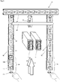
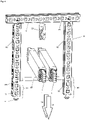
- the mounting device 9 shown and a lifting device 4 with two supporting devices 41A, 41B, which are used for the installation of busbars 1 in the ceiling 8 of a building.
- the mounting device 9 comprises a horizontal profile 91 mounted on the ceiling 8 and two designed as threaded rods Vertical profiles 92, between which the busbars 1 can be raised by means of the support devices 41A, 41B and associated traction cables 44A, 44B.
- a mounting profile 99 is used above the horizontal profile 91 to fasten the traction cables 44A, 44B.
- the traction cables 44A, 44B run via a first deflection roller 95, which is held at a first end of the mounting profile 99, further over two deflection rollers 45A, 45B on the support devices 41A, 41B and further to the second end of the mounting profile 99.
- the busbars 1 are held on the front side by the first support device 41A and on the rear side by the second support device 41B.
- the two threaded rods 92 can be connected to an inserted support profile 93 by means of first nuts 921 and second nuts 922, onto which the conductor rails 1 raised against the horizontal profile 91 are lowered.
- This lifting device 4 has various disadvantages. Before the busbars 1 can be pulled up, a considerable amount of installation work is required. First the mounting profile 99 has to be mounted on the ceiling 8. In the embodiment shown, this is inserted above the horizontal profile 91 where it takes up space. Then the carrying devices 41A, 41B are to be provided and the traction cables 44A, 44B to be assembled.
- the heavy conductor rails 1 have to be lifted and placed on the carrying devices 41A, 41B. Only now can the carrying devices 41A, 41B be raised with the conductor rails 1. Now, however, it should be noted that lifting the carrying devices 41A, 41B by strong personnel is extremely dangerous. In the event of a mishap, for example if a traction cable is accidentally released or if the carrying devices 41A, 41B are pulled up unevenly, the conductor rails 1 could fall from the carrying devices 41A, 41B and injure people on the one hand and be destroyed by the impact on the other.
- the carrying devices 41A, 41B which are held by the traction cables 44A, 44B by means of the deflection rollers 45A, 45B, do not tilt to one side or the other.
- the carrying devices 41A, 41B are therefore to be kept in a horizontal alignment for safety reasons, e.g. by additional ropes.
- EP1589627B1 also proposed to provide each of the support devices 41A, 41B with two drive units.
- this solution is still significantly more complex than the solution without entrained drive units.
- the supporting devices 41A, 41B take up space and have a considerable weight. With regard to the support devices 41A, 41B, it should also be noted that they cannot be raised all the way to the ceiling 8, which is why more space is required for the installation of the conductor rails 1.
- the mounting devices must be mounted on the ceiling.
- the conductor rails have to be lifted and the assembly devices have to be operated. Ie, the support profile must removed before raising the busbars and reinserted after raising the busbars.
- An assembly group is therefore to be provided for the installation of the assembly devices and another assembly group is responsible for lifting the conductor rails, while at least one other person standing on a ladder operates the assembly device or the support profile.
- the installation of the busbars with the known device is therefore labor-intensive and associated with risks.
- Another installation device for attaching power rails to a ceiling is also in EP1905723A1 disclosed.
- the present invention is therefore based on the object of specifying an improved device for installing busbars and an improved installation method by means of which busbars can be mounted in a mounting device.
- the installation device should have a simple design and cause only a small amount of material and costs. Furthermore, the installation device should be quick and easy to use.
- Auxiliary devices that are already present on a construction site should be able to be used advantageously without new devices having to be created.
- the installation material required for the installation should take up hardly any space and be easy to transport to the installation site. By avoiding voluminous parts of the device, it should be possible to pull the busbars up to the ceiling at most.
- the conductor rails should be installable without safety risks.
- the conductor rails should always be secured, even in the event of incorrect manipulation.
- busbars should also be able to be raised mechanically with simple means, so that installation is possible without any effort.
- the process of raising the busbars and the process of installing and operating the fixtures intended to hold the busbars on a ceiling should be able to be combined with each other, so that the entire installation process is simplified and less manpower is required.
- the installation device provided for the assembly of at least one conductor rail comprises assembly devices that are mounted on a building ceiling, two lifting devices that each have a traction device and each have a deflection roller connected to the associated assembly device.
- At least one working platform is provided with a working platform and, if necessary, a railing, on which in the area of the working platform for each of the lifting devices a pulling device is attached by connecting means, by means of which the associated pulling means, which is guided over the associated deflection roller and which is connected to an end piece with the at least one busbar can be connected, can be pulled in order to pull the at least one busbar up into the mounting devices in which it can be fixed.
- the towing devices are secured and fixed by connecting the towing devices to the work platform.
- Detachable connecting means such as snap hooks, are preferably provided, which are connected to the structure, possibly the railing of the working platform.
- the pulling devices can therefore be used to install the conductor rails and then removed again as required.
- the work platform which has a relatively large dead weight, forms the counterweight to the raised power rails. If necessary, the weight of the work platform is increased by ballast. According to the invention, the work platform is thus functionally combined with the traction devices, so that the essential problem of fixing and securing the traction devices is solved.
- the work platform preferably has casters or wheels so that it can be easily driven to an installation site or moved as needed.
- the installation device according to the invention or with the installation method according to the invention only a small number of personnel are required.
- the installation of the conductor rails could be carried out by a single person. This is particularly the case when a control device is present which allows the traction devices or their drive devices to be activated synchronously.
- the drive devices are wired or wirelessly each connected or connectable to a control unit connected by wire or wirelessly to a common control unit, by means of which the drive devices can be operated synchronously and, if necessary, also asynchronously.
- the traction devices can comprise a manually operable drive device or a drive device with an electric motor.
- the drive device can be integrated into the traction device or can be coupled to this construction. For example, it is possible to couple a drill or a drive device for a screwdriver with the pulling device.
- the traction device or cable winch has a safety device that prevents the traction device or traction cable from slipping back under the load of the power rail.
- the traction mechanism is, for example, wrapped around a roller several times and clamped in it. In this way, the traction means is clamped even more tightly with increasing load and can no longer retreat.
- the traction means is preferably released after passing through the traction device and is not wound up on a roll. By doing without a winding roller, the weight and dimensions of the pulling device can be reduced to a minimum.
- the towing devices that can be connected to the work platform can thus be of simple design and themselves have only a very low weight. Since work platforms are already in place during the construction phase of a project for various works, the personnel responsible for installing the busbars need to bring very little and very light installation material to the installation site. A voluminous and relatively heavy carrying device, as is known from the prior art, is avoided. The installation material to be carried by the installation personnel fits into a case that can be conveniently carried to the installation site.
- the reliable securing of the installation device completely eliminates risks for the personnel.
- the conductor rails can also be easily installed without any effort.
- the end pieces of the traction means facing the busbars can preferably be connected by a hook to a preferably band-shaped loop, which is used to hold the busbar.
- the conductor rails are provided with mounting elements that can be coupled to the traction mechanism.
- the mounting devices have a horizontal profile that can be mounted or is mounted on the building ceiling, which is connected to two vertical profiles spaced apart from one another, on which a support profile is mounted that carries the conductor rail and that can be removed to pull up the conductor rail and after the conductor rail has been pulled up can be used again.
- the assembly devices preferably have adjusting devices, by means of which the height, position and alignment of the installed busbars can be adjusted, so that adjacent busbars can be aligned axially with one another and connected to one another precisely.
- the deflection rollers required for the pulling devices or the pulling means are each detachably connected to the associated horizontal profile or are each integrated into the associated horizontal profile.
- the integration of a deflection roller in a horizontal profile which can be implemented at low cost, leads to a further simplification of the installation process.
- the integration of the pulley in the horizontal profiles also has the advantage that the conductor rails can be pulled up to the horizontal profiles.
- FIG. 2a shows an exploded view of a mounting device 9 according to the invention, which has a horizontal profile 91 and two vertical profiles 92 connected thereto, as well as two adjusting devices 94 and a support profile 93.
- the horizontal profile 91 and the vertical profiles 92 are cut from a uniform metal profile.
- the metal profile comprises three side plates with round and rectangular openings 98, 99 arranged alternately in a grid. At the ends of the side plates, which are aligned parallel to one another, end strips 97 which are rotated in relation to one another and have teeth are provided.
- a C-profile is formed by the side plates and the end strips 97, which encloses a receiving channel 90 which is open on one side and has an at least approximately rectangular cross section.
- the two vertical profiles 92 arranged perpendicularly to the horizontal profile 91 are aligned in such a way that their receiving channels 90 face each other, so that the ends of the support profile 93 can be inserted into them on both sides and coupled to the adjusting device 94 .
- the in Figure 2b shown connecting device 7 which has a first and a second anchor element 72, 73 with threaded bores which can be connected to one another by a connecting screw 71.
- a connecting screw 71 Possible is also the use of two identical anchor elements 73.
- the anchor elements 72 or 73 are inserted into openings 99 in the horizontal profile 91 and a vertical profile 92 and pulled against one another by the connecting screw 71.
- the horizontal profile 91 and the vertical profiles 92 can therefore be stably connected to one another in a simple manner.
- Adjusting devices 94 are preferably arranged in the vertical profiles 92 or the receiving channels 90 provided therein, each of which comprises an anchor element 73 connected to the associated vertical profile 92, an adjusting screw 71 held rotatably in a threaded bore in the anchor element 73 and a bearing element 940, which is supported by the adjusting screw 71 can be slidably held within the receiving channel 90.
- the bearing element 941 comprises a receiving sleeve 941 which serves to receive the shank of the adjusting screw 71 and which is connected to a U-profile element 942 which is open at the top and serves to receive the support element 93 .
- the bearing element 940 which is aligned coaxially with the adjusting screw 71 , is designed in the shape of a fork and can accommodate an end piece of the support element 93 .
- the adjusting screw 71 By turning the adjusting screw 71, the held end piece of the support element 93 can be adjusted in height.
- the support profile 93 can be adjusted in height and inclination.
- the horizontal profile 91 is connected to a deflection roller 54 which has a running wheel 541 and a mounting part 542 .
- the deflection roller 54 is shown enlarged.
- the deflection roller 54 or the running wheel 541 can advantageously also be integrated into the horizontal profile 91 .
- the running wheel 541 is inserted into the receiving channel 90 of the horizontal profile 91 and fixed by the wheel axle 543, which is guided through adjacent openings 98. This results in the manufacture of the horizontal profile 91, a small additional effort, which is caused by the corresponding relief in the installation work is more than compensated.
- FIG. 3 shows the mounting device 9 mounted on a building ceiling Figure 2a during the adjustment of the support element 93.
- the left vertical profile 92 is shown in a sectional view, so that the adjustment device 94 mounted in the receiving channel 90 is visible. It shows that the shank of the adjusting screw 71 is aligned parallel to the axis of the associated vertical profile 92 and protrudes downwards so that the screw head can be gripped and rotated.
- FIG 4 shows the assembly device 9 of FIG 3 after inserting the support element 93 and lowering the two conductor rails 1.
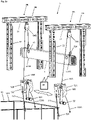
- Figure 5a shows an installation device 5 according to the invention with two assembly devices 9A, 9B mounted on the building ceiling and a working platform 51 which comprises a frame 512, a working platform 511 and a railing 513. Personnel can move on the working platform 511 in order to assemble the assembly devices 9A, 9B and then pull up one or more conductor rails.
- the working platform 51 is preferably adjustable in height and can preferably be moved on wheels or rollers.
- Two lifting devices 5A, 5B according to the invention are provided for pulling up the conductor rail 1, each of which has a pulling device or cable pulling device 52A; 52B with a traction means or traction cable 53A; 53B.
- the pulling devices 52A; 52B are detachably fastened to the working platform 51 in the area of the working platform 511 or to the railing 513 by means of connecting means 523, 524.
- the traction means 53A; 53B is not rolled up, but is held and carried away downwards during operation of the pulling devices 52A, 52B.
- the pulling devices 52A, 52B comprise a drive unit 521, typically an electric motor or as symbolically shown, a crank that is manually operable. Suitable traction devices that are used in the field of mountain rescue, for example, from the EP0624387A1 or the EP3212297B1 known.
- the traction means 53A; 53B are each guided to a conductor rail 1 via a deflection roller 54A, 54B, which is mounted on the associated mounting device 9A, 9B or is integrated therein.
- the ends 531A, 531B of the traction means 53A, 53B are designed as loops which enclose the conductor rail 1.
- a blocking unit prevents the drive shafts of the drive units 521 from being able to turn back.
- the drive shafts are preferably coupled to a gear wheel on which a rotatably mounted locking lever rests, which is raised by each tooth of the gear wheel when the train is tightened and then falls back between two teeth.
- the blocking lever engages between two teeth of the gear wheel and prevents further rotation of the drive shaft. If an electric motor fails or the manual operation of the drive crank is interrupted, the drive shaft is blocked immediately.
- the support profile 93 is then inserted into the vertical profiles 92. If the deflection rollers 54A, 54B are integrated into the horizontal profiles 91, the conductor rail 1 can be pulled all the way up to the stop on the horizontal profiles 91.
- Figure 5b shows the end of a traction device 53, which is connected by eyelets 5311 and hooks 5312 to a mounting loop 531'.
- the mounting loop 531' can be placed around the conductor rail 1, after which the hook 5312 can be inserted into the eyelets 5311 is introduced.
- One or more conductor rails 1 can therefore be connected to the traction means 53 quickly and safely.
- the conductor rail 1 preferably has a marking or indentation at the relevant assembly points, which serves to accommodate the cable by means of 53 or the assembly loop 531'.
- Figure 5c shows the installation device 5 in an enlarged view.
- the pulling devices 52A, 52B are shown to be detachably connected to the railing 513 of the work platform 51 by connecting parts or connecting rods 523 and snap hooks 524 .
- the drive devices 521 which are represented symbolically with a crank, include electric motors that are controlled synchronously or asynchronously by means of a control unit 50. Both pulling devices 52A, 52B can therefore be controlled by one person, preferably remotely.
- the other ends 531 are provided with a snap hook 524, by means of which the loop 531B or 531B, which is guided around the conductor rail 1, is closed.
- the traction means 53A or 53B is therefore guided around the conductor rail 1, after which the snap hook 524 is hooked into the traction means 53A or 53B.
- the connection to the busbar 1 can therefore be completed in a few simple steps.
- the conductor rods of high-quality busbars are e.g. cast in cast resin or epoxy cement or polymer concrete and thus achieve protection class IP68. Corresponding shaped elements can therefore be molded into the casting compound. In the case of busbars with a metal housing, this can be provided with the appropriate mounting elements.
Landscapes
- Engineering & Computer Science (AREA)
- Architecture (AREA)
- Civil Engineering (AREA)
- Structural Engineering (AREA)
- Conveying And Assembling Of Building Elements In Situ (AREA)
Claims (15)
- Dispositif d'installation (5) pour le montage d'au moins une barre omnibus (1) avec des dispositifs de montage (9A, 9B), qui peuvent être montés sur un plafond de bâtiment (8), avec deux dispositifs de levage (5A, 5B), qui comportent chacun un moyen de traction (53A, 53B) et chacun une poulie de renvoi (54A, 54B) reliée au dispositif de montage (9A ; 9B) correspondant, caractérisé en ce qu'il est prévu au moins une terrasse de travail (51) avec une plateforme de travail (511) et éventuellement une balustrade (513), sur laquelle est fixé, dans la zone de la plateforme de travail (511), par des moyens de liaison (523, 524), pour chacun des dispositifs de levage (5A, 5B), un dispositif de traction (52A ; 52B), au moyen duquel le moyen de traction (53A ; 53B) correspondant, qui est guidé par la poulie de renvoi (54A ; 54B) correspondante et qui peut être relié par une pièce d'extrémité (531A ; 531B) à l'au moins une barre omnibus (1), peut être tiré, afin de hisser l'au moins une barre omnibus (1) dans les dispositifs de montage (9A, 9B) dans lesquels elle peut être fixée.
- Dispositif d'installation (5) selon la revendication 1, caractérisé en ce que les dispositifs de traction (52A ; 52B) comprennent chacun un dispositif d'entraînement (521) pour l'entraînement motorisé ou manuel.
- Dispositif d'installation (5) selon la revendication 2, caractérisé en ce que les dispositifs d'entraînement (521) sont reliés par fil ou sans fil chacun à une unité de commande (50) ou peuvent être reliés à celle-ci, ou en ce que les dispositifs d'entraînement (521) sont reliés par fil ou sans fil à une unité de commande commune (50) au moyen de laquelle les dispositifs d'entraînement (521) peuvent être actionnés de manière synchrone.
- Dispositif d'installation (5) selon la revendication 1, 2 ou 3, caractérisé en ce que les dispositifs de traction (52A ; 52B) maintiennent le moyen de traction (53A ; 53B) par un galet ou en ce que le moyen de traction (53A ; 53B) maintenu par les dispositifs de traction (52A ; 52B), entourant éventuellement un galet de traction une ou plusieurs fois, traverse les dispositifs de traction (52A ; 52B).
- Dispositif d'installation (5) selon une des revendications 1 - 4, caractérisé en ce que les dispositifs de traction (52A ; 52B) sont reliés par des moyens de liaison amovibles, tels que des mousquetons (524), à la structure, éventuellement une balustrade (513), de la terrasse de travail (51).
- Dispositif d'installation (5) selon une des revendications 1 - 5, caractérisé en ce que les moyens de traction (53A ; 53B) sont des cordes et les dispositifs de traction (52A ; 52B) sont des treuils.
- Dispositif d'installation (5) selon une des revendications 1 - 6, caractérisé en ce que la terrasse de travail peut être déplacée sur des roues.
- Dispositif d'installation (5) selon une des revendications 1 - 7, caractérisé en ce que les pièces d'extrémité (531A, 531B) des moyens de traction (53A ; 53B) orientées vers les barres omnibus (1) peuvent être reliées par un crochet (5312) à une boucle (531') de préférence en forme de bande qui sert à maintenir la barre omnibus (1), ou en ce que les pièces d'extrémité (531A, 531B) des moyens de traction (53A ; 53B) orientées vers les barres omnibus (1) peuvent être reliées à des éléments de montage (10) de la barre omnibus (1) .
- Dispositif d'installation (5) selon une des revendications 1 - 8, caractérisé en ce que les dispositifs de montage (9A ; 9b) comprennent un profilé horizontal (91) pouvant être monté sur le plafond de bâtiment (8), qui est muni de deux profilés verticaux (92) espacés l'un de l'autre, sur lesquels est monté un profilé porteur (93) qui porte la barre omnibus (1) et qui peut être enlevé pour soulever la barre omnibus (1) et qui peut être remis en place après le soulèvement de la barre omnibus (1).
- Dispositif d'installation (5) selon une des revendications 1 - 9, caractérisé en ce que les dispositifs de montage (9A ; 9b) présentent des dispositifs d'ajustement (94) au moyen desquels la hauteur, la position et l'orientation des barres omnibus installées (1) peuvent être ajustées.
- Dispositif d'installation (5) selon une des revendications 1 - 10, caractérisé en ce que les poulies de renvoi (54A, 54B) sont reliées chacune de manière amovible au profilé horizontal (91) correspondant ou en ce que les poulies de renvoi (54A, 54B) sont intégrées chacune dans le profilé horizontal (91) correspondant.
- Procédé d'installation d'une barre omnibus (1) avec un dispositif d'installation (5) selon une des revendications 1 - 11, caractérisé en ce, que- il est prévu une terrasse de travail (51) avec une plateforme de travail (511) et éventuellement une balustrade (513);- par des moyens de liaison (523, 524) de préférence amovibles, deux dispositifs de traction (52A, 52B), qui sont ou seront munis chacun d'un moyen de traction (53A ; 53B), sont reliés à la terrasse de travail (51) dans la zone de la plateforme de travail (511);- au moins deux dispositifs de montage (9A, 9b), qui servent à l'installation de la barre omnibus (1) et qui présentent à cet effet chacun un profilé porteur (93), sont montés sur le plafond de bâtiment (8);- les dispositifs de montage (9A, 9b) sont munis chacun d'une poulie de renvoi (54A ; 54B) à la position où la barre omnibus (1) doit être relevée;- les moyens de traction (53A ; 53B) sont insérés dans les poulies (54A ; 54B) et reliés à la barre omnibus (1) à installer;- les dispositifs de traction (52A, 52B) sont actionnés pour soulever la barre omnibus (1); et- la barre omnibus (1) est fixée dans les dispositifs de montage (9A, 9b).
- Procédé d'installation (5) selon la revendication 12, caractérisé en ce que les dispositifs de montage (9A, 9b) comprennent chacun un profilé horizontal (91), deux profilés verticaux (92) reliés à celui-ci ainsi qu'un profilé porteur (93) pouvant être relié aux profilés verticaux (92) et en ce que les profilés horizontaux (91) sont montés sur le plafond de bâtiment (8) et sont de préférence équipés au milieu par la poulie de renvoi (54A, 54B) ou que les profilés horizontaux (91) déjà munis des poulies de renvoi (54 A, 54 B) sont montés sur le plafond de bâtiment (8).
- Procédé d'installation (5) selon la revendication 12 ou 13, caractérisé en ce que les dispositifs de traction (52A, 52B) sont chacun pourvus d'un dispositif d'entraînement (521) à commande électrique, qui sont chacun commandés par une unité de commande (50) prévue individuellement ou une unité de commande (50) utilisée en commun, pour soulever la barre omnibus (1).
- Procédé d'installation (5) selon la revendication 12, 13 ou 14, caractérisé en ce que les profilés porteurs (93) sont enlevés avant le levage de la barre omnibus (1) et insérés dans les dispositifs de montage (9A, 9B) après le levage de la barre omnibus (1) et que les dispositifs de montage (9A ; 9b) présentent des dispositifs d'ajustement (94) au moyen desquels la hauteur, la position et l'orientation de la barre omnibus (1) reposant sur les profilés porteurs sont ajustées en cas de besoin.
Priority Applications (1)
| Application Number | Priority Date | Filing Date | Title |
|---|---|---|---|
| EP19205053.2A EP3813210B1 (fr) | 2019-10-24 | 2019-10-24 | Dispositif d'installation pour barres omnibus ainsi que procédé d'installation |
Applications Claiming Priority (1)
| Application Number | Priority Date | Filing Date | Title |
|---|---|---|---|
| EP19205053.2A EP3813210B1 (fr) | 2019-10-24 | 2019-10-24 | Dispositif d'installation pour barres omnibus ainsi que procédé d'installation |
Publications (2)
| Publication Number | Publication Date |
|---|---|
| EP3813210A1 EP3813210A1 (fr) | 2021-04-28 |
| EP3813210B1 true EP3813210B1 (fr) | 2022-09-21 |
Family
ID=68342776
Family Applications (1)
| Application Number | Title | Priority Date | Filing Date |
|---|---|---|---|
| EP19205053.2A Active EP3813210B1 (fr) | 2019-10-24 | 2019-10-24 | Dispositif d'installation pour barres omnibus ainsi que procédé d'installation |
Country Status (1)
| Country | Link |
|---|---|
| EP (1) | EP3813210B1 (fr) |
Family Cites Families (4)
| Publication number | Priority date | Publication date | Assignee | Title |
|---|---|---|---|---|
| DE4315952C2 (de) | 1993-05-12 | 1997-05-07 | Anton Staltmeir | Abseil- und Aufseilgerät |
| EP1589627B1 (fr) | 2004-04-20 | 2007-03-21 | Zurecon Ag | Dispositif de levage et de fixation pour barres omnibus |
| ATE533724T1 (de) * | 2006-09-30 | 2011-12-15 | Zurecon Ag | Hebevorrichtung für die montage von stromschienen |
| DE202015001685U1 (de) | 2015-03-05 | 2015-03-23 | Mittelmann Sicherheitstechnik Gmbh & Co. Kg | Abseilgerät |
-
2019
- 2019-10-24 EP EP19205053.2A patent/EP3813210B1/fr active Active
Also Published As
| Publication number | Publication date |
|---|---|
| EP3813210A1 (fr) | 2021-04-28 |
Similar Documents
| Publication | Publication Date | Title |
|---|---|---|
| DE102010031208B4 (de) | Vorrichtung und Verfahren zur Aufstiegssicherung | |
| EP2556008A2 (fr) | Procédé et dispositif pour ériger un mât d'une éolienne | |
| EP3042011B1 (fr) | Procédé de montage d'équipements d'une tour | |
| EP3491205A1 (fr) | Élément de fixation | |
| AT510762A1 (de) | Seilzugeinrichtung, insbesondere prospektzuganlage für eine bühne oder dgl. | |
| EP1905723B1 (fr) | Dispositif de levage pour le montage de rails conducteurs | |
| WO2006097505A1 (fr) | Plateforme de travail | |
| DE102017128143B3 (de) | Wartungsplattform zur Wartung von Einbauten in einem Turm für eine Windenergieanlage und Anordnung einer Wartungsplattform | |
| EP1772411A1 (fr) | Méthode pour installer un moyen de support d'une cabine d'ascenseur sur une cabine d'ascenseur et dans une gaine d'ascenseur | |
| EP2823860B1 (fr) | Système de sécurité pour personnes | |
| EP3813210B1 (fr) | Dispositif d'installation pour barres omnibus ainsi que procédé d'installation | |
| EP1589627B1 (fr) | Dispositif de levage et de fixation pour barres omnibus | |
| EP3440287A1 (fr) | Élément de fixation de coffrage de paroi | |
| DE102017124233A1 (de) | Schelleneinheit für Hydraulikleitungen | |
| DE102012004144B4 (de) | Vorrichtung zum Einbau von mindestens einem Seil, insbesondere im Bereich des Gerüstbaus, und Verfahren für den Einbau von Seilen | |
| DE102017009291A1 (de) | Windenmontagerahmen und Windenanordnung | |
| EP4385598B1 (fr) | Dispositif pour maintenir au moins une personne | |
| DE10243356A1 (de) | Zerlegbares Gerüst | |
| DE1907947B2 (de) | Tragbare winde | |
| EP2482130A1 (fr) | Système de traction flexible pour systèmes d'écran et procédé de montage de systèmes d'écran | |
| EP3002394B1 (fr) | Mât ayant un haubanage | |
| DE202017107205U1 (de) | Befestigungsvorrichtung für Stromschienen | |
| DE102009049648B4 (de) | Vorrichtung und Verfahren zur Unterstützung von Rettungs-, Bergungs- oder Aufräumarbeiten aus der Luft | |
| DE4430759C2 (de) | Verfahren und Vorrichtung zum Auswechseln eines Mastkopfes eines Winkeltragmastes einer Hochspannungsfreileitung | |
| DE3215328A1 (de) | Sicherungsvorrichtung fuer absturzgefaehrdete personen |
Legal Events
| Date | Code | Title | Description |
|---|---|---|---|
| PUAI | Public reference made under article 153(3) epc to a published international application that has entered the european phase |
Free format text: ORIGINAL CODE: 0009012 |
|
| STAA | Information on the status of an ep patent application or granted ep patent |
Free format text: STATUS: THE APPLICATION HAS BEEN PUBLISHED |
|
| AK | Designated contracting states |
Kind code of ref document: A1 Designated state(s): AL AT BE BG CH CY CZ DE DK EE ES FI FR GB GR HR HU IE IS IT LI LT LU LV MC MK MT NL NO PL PT RO RS SE SI SK SM TR |
|
| AX | Request for extension of the european patent |
Extension state: BA ME |
|
| STAA | Information on the status of an ep patent application or granted ep patent |
Free format text: STATUS: REQUEST FOR EXAMINATION WAS MADE |
|
| 17P | Request for examination filed |
Effective date: 20211028 |
|
| RBV | Designated contracting states (corrected) |
Designated state(s): AL AT BE BG CH CY CZ DE DK EE ES FI FR GB GR HR HU IE IS IT LI LT LU LV MC MK MT NL NO PL PT RO RS SE SI SK SM TR |
|
| GRAP | Despatch of communication of intention to grant a patent |
Free format text: ORIGINAL CODE: EPIDOSNIGR1 |
|
| STAA | Information on the status of an ep patent application or granted ep patent |
Free format text: STATUS: GRANT OF PATENT IS INTENDED |
|
| RIC1 | Information provided on ipc code assigned before grant |
Ipc: H02G 5/00 20060101ALN20220318BHEP Ipc: H02G 3/00 20060101ALI20220318BHEP Ipc: H02G 1/00 20060101AFI20220318BHEP |
|
| INTG | Intention to grant announced |
Effective date: 20220406 |
|
| GRAS | Grant fee paid |
Free format text: ORIGINAL CODE: EPIDOSNIGR3 |
|
| GRAA | (expected) grant |
Free format text: ORIGINAL CODE: 0009210 |
|
| STAA | Information on the status of an ep patent application or granted ep patent |
Free format text: STATUS: THE PATENT HAS BEEN GRANTED |
|
| AK | Designated contracting states |
Kind code of ref document: B1 Designated state(s): AL AT BE BG CH CY CZ DE DK EE ES FI FR GB GR HR HU IE IS IT LI LT LU LV MC MK MT NL NO PL PT RO RS SE SI SK SM TR |
|
| REG | Reference to a national code |
Ref country code: GB Ref legal event code: FG4D Free format text: NOT ENGLISH |
|
| REG | Reference to a national code |
Ref country code: CH Ref legal event code: EP |
|
| REG | Reference to a national code |
Ref country code: DE Ref legal event code: R096 Ref document number: 502019005702 Country of ref document: DE |
|
| REG | Reference to a national code |
Ref country code: IE Ref legal event code: FG4D Free format text: LANGUAGE OF EP DOCUMENT: GERMAN |
|
| REG | Reference to a national code |
Ref country code: AT Ref legal event code: REF Ref document number: 1520441 Country of ref document: AT Kind code of ref document: T Effective date: 20221015 |
|
| REG | Reference to a national code |
Ref country code: LT Ref legal event code: MG9D |
|
| REG | Reference to a national code |
Ref country code: NL Ref legal event code: MP Effective date: 20220921 |
|
| PG25 | Lapsed in a contracting state [announced via postgrant information from national office to epo] |
Ref country code: SE Free format text: LAPSE BECAUSE OF FAILURE TO SUBMIT A TRANSLATION OF THE DESCRIPTION OR TO PAY THE FEE WITHIN THE PRESCRIBED TIME-LIMIT Effective date: 20220921 Ref country code: RS Free format text: LAPSE BECAUSE OF FAILURE TO SUBMIT A TRANSLATION OF THE DESCRIPTION OR TO PAY THE FEE WITHIN THE PRESCRIBED TIME-LIMIT Effective date: 20220921 Ref country code: NO Free format text: LAPSE BECAUSE OF FAILURE TO SUBMIT A TRANSLATION OF THE DESCRIPTION OR TO PAY THE FEE WITHIN THE PRESCRIBED TIME-LIMIT Effective date: 20221221 Ref country code: LV Free format text: LAPSE BECAUSE OF FAILURE TO SUBMIT A TRANSLATION OF THE DESCRIPTION OR TO PAY THE FEE WITHIN THE PRESCRIBED TIME-LIMIT Effective date: 20220921 Ref country code: LT Free format text: LAPSE BECAUSE OF FAILURE TO SUBMIT A TRANSLATION OF THE DESCRIPTION OR TO PAY THE FEE WITHIN THE PRESCRIBED TIME-LIMIT Effective date: 20220921 Ref country code: FI Free format text: LAPSE BECAUSE OF FAILURE TO SUBMIT A TRANSLATION OF THE DESCRIPTION OR TO PAY THE FEE WITHIN THE PRESCRIBED TIME-LIMIT Effective date: 20220921 |
|
| PG25 | Lapsed in a contracting state [announced via postgrant information from national office to epo] |
Ref country code: HR Free format text: LAPSE BECAUSE OF FAILURE TO SUBMIT A TRANSLATION OF THE DESCRIPTION OR TO PAY THE FEE WITHIN THE PRESCRIBED TIME-LIMIT Effective date: 20220921 Ref country code: GR Free format text: LAPSE BECAUSE OF FAILURE TO SUBMIT A TRANSLATION OF THE DESCRIPTION OR TO PAY THE FEE WITHIN THE PRESCRIBED TIME-LIMIT Effective date: 20221222 |
|
| PG25 | Lapsed in a contracting state [announced via postgrant information from national office to epo] |
Ref country code: SM Free format text: LAPSE BECAUSE OF FAILURE TO SUBMIT A TRANSLATION OF THE DESCRIPTION OR TO PAY THE FEE WITHIN THE PRESCRIBED TIME-LIMIT Effective date: 20220921 Ref country code: RO Free format text: LAPSE BECAUSE OF FAILURE TO SUBMIT A TRANSLATION OF THE DESCRIPTION OR TO PAY THE FEE WITHIN THE PRESCRIBED TIME-LIMIT Effective date: 20220921 Ref country code: PT Free format text: LAPSE BECAUSE OF FAILURE TO SUBMIT A TRANSLATION OF THE DESCRIPTION OR TO PAY THE FEE WITHIN THE PRESCRIBED TIME-LIMIT Effective date: 20230123 Ref country code: ES Free format text: LAPSE BECAUSE OF FAILURE TO SUBMIT A TRANSLATION OF THE DESCRIPTION OR TO PAY THE FEE WITHIN THE PRESCRIBED TIME-LIMIT Effective date: 20220921 Ref country code: CZ Free format text: LAPSE BECAUSE OF FAILURE TO SUBMIT A TRANSLATION OF THE DESCRIPTION OR TO PAY THE FEE WITHIN THE PRESCRIBED TIME-LIMIT Effective date: 20220921 |
|
| PG25 | Lapsed in a contracting state [announced via postgrant information from national office to epo] |
Ref country code: SK Free format text: LAPSE BECAUSE OF FAILURE TO SUBMIT A TRANSLATION OF THE DESCRIPTION OR TO PAY THE FEE WITHIN THE PRESCRIBED TIME-LIMIT Effective date: 20220921 Ref country code: PL Free format text: LAPSE BECAUSE OF FAILURE TO SUBMIT A TRANSLATION OF THE DESCRIPTION OR TO PAY THE FEE WITHIN THE PRESCRIBED TIME-LIMIT Effective date: 20220921 Ref country code: IS Free format text: LAPSE BECAUSE OF FAILURE TO SUBMIT A TRANSLATION OF THE DESCRIPTION OR TO PAY THE FEE WITHIN THE PRESCRIBED TIME-LIMIT Effective date: 20230121 Ref country code: EE Free format text: LAPSE BECAUSE OF FAILURE TO SUBMIT A TRANSLATION OF THE DESCRIPTION OR TO PAY THE FEE WITHIN THE PRESCRIBED TIME-LIMIT Effective date: 20220921 |
|
| REG | Reference to a national code |
Ref country code: DE Ref legal event code: R097 Ref document number: 502019005702 Country of ref document: DE |
|
| REG | Reference to a national code |
Ref country code: BE Ref legal event code: MM Effective date: 20221031 |
|
| PG25 | Lapsed in a contracting state [announced via postgrant information from national office to epo] |
Ref country code: NL Free format text: LAPSE BECAUSE OF FAILURE TO SUBMIT A TRANSLATION OF THE DESCRIPTION OR TO PAY THE FEE WITHIN THE PRESCRIBED TIME-LIMIT Effective date: 20220921 Ref country code: MC Free format text: LAPSE BECAUSE OF FAILURE TO SUBMIT A TRANSLATION OF THE DESCRIPTION OR TO PAY THE FEE WITHIN THE PRESCRIBED TIME-LIMIT Effective date: 20220921 Ref country code: LU Free format text: LAPSE BECAUSE OF NON-PAYMENT OF DUE FEES Effective date: 20221024 Ref country code: AL Free format text: LAPSE BECAUSE OF FAILURE TO SUBMIT A TRANSLATION OF THE DESCRIPTION OR TO PAY THE FEE WITHIN THE PRESCRIBED TIME-LIMIT Effective date: 20220921 |
|
| P01 | Opt-out of the competence of the unified patent court (upc) registered |
Effective date: 20230529 |
|
| PLBE | No opposition filed within time limit |
Free format text: ORIGINAL CODE: 0009261 |
|
| STAA | Information on the status of an ep patent application or granted ep patent |
Free format text: STATUS: NO OPPOSITION FILED WITHIN TIME LIMIT |
|
| PG25 | Lapsed in a contracting state [announced via postgrant information from national office to epo] |
Ref country code: DK Free format text: LAPSE BECAUSE OF FAILURE TO SUBMIT A TRANSLATION OF THE DESCRIPTION OR TO PAY THE FEE WITHIN THE PRESCRIBED TIME-LIMIT Effective date: 20220921 |
|
| 26N | No opposition filed |
Effective date: 20230622 |
|
| PG25 | Lapsed in a contracting state [announced via postgrant information from national office to epo] |
Ref country code: SI Free format text: LAPSE BECAUSE OF FAILURE TO SUBMIT A TRANSLATION OF THE DESCRIPTION OR TO PAY THE FEE WITHIN THE PRESCRIBED TIME-LIMIT Effective date: 20220921 |
|
| PG25 | Lapsed in a contracting state [announced via postgrant information from national office to epo] |
Ref country code: BE Free format text: LAPSE BECAUSE OF NON-PAYMENT OF DUE FEES Effective date: 20221031 |
|
| PG25 | Lapsed in a contracting state [announced via postgrant information from national office to epo] |
Ref country code: IE Free format text: LAPSE BECAUSE OF NON-PAYMENT OF DUE FEES Effective date: 20221024 |
|
| PG25 | Lapsed in a contracting state [announced via postgrant information from national office to epo] |
Ref country code: CY Free format text: LAPSE BECAUSE OF FAILURE TO SUBMIT A TRANSLATION OF THE DESCRIPTION OR TO PAY THE FEE WITHIN THE PRESCRIBED TIME-LIMIT Effective date: 20220921 |
|
| PG25 | Lapsed in a contracting state [announced via postgrant information from national office to epo] |
Ref country code: MK Free format text: LAPSE BECAUSE OF FAILURE TO SUBMIT A TRANSLATION OF THE DESCRIPTION OR TO PAY THE FEE WITHIN THE PRESCRIBED TIME-LIMIT Effective date: 20220921 Ref country code: IT Free format text: LAPSE BECAUSE OF FAILURE TO SUBMIT A TRANSLATION OF THE DESCRIPTION OR TO PAY THE FEE WITHIN THE PRESCRIBED TIME-LIMIT Effective date: 20220921 Ref country code: HU Free format text: LAPSE BECAUSE OF FAILURE TO SUBMIT A TRANSLATION OF THE DESCRIPTION OR TO PAY THE FEE WITHIN THE PRESCRIBED TIME-LIMIT; INVALID AB INITIO Effective date: 20191024 |
|
| GBPC | Gb: european patent ceased through non-payment of renewal fee |
Effective date: 20231024 |
|
| PG25 | Lapsed in a contracting state [announced via postgrant information from national office to epo] |
Ref country code: TR Free format text: LAPSE BECAUSE OF FAILURE TO SUBMIT A TRANSLATION OF THE DESCRIPTION OR TO PAY THE FEE WITHIN THE PRESCRIBED TIME-LIMIT Effective date: 20220921 |
|
| PG25 | Lapsed in a contracting state [announced via postgrant information from national office to epo] |
Ref country code: GB Free format text: LAPSE BECAUSE OF NON-PAYMENT OF DUE FEES Effective date: 20231024 |
|
| PG25 | Lapsed in a contracting state [announced via postgrant information from national office to epo] |
Ref country code: GB Free format text: LAPSE BECAUSE OF NON-PAYMENT OF DUE FEES Effective date: 20231024 Ref country code: BG Free format text: LAPSE BECAUSE OF FAILURE TO SUBMIT A TRANSLATION OF THE DESCRIPTION OR TO PAY THE FEE WITHIN THE PRESCRIBED TIME-LIMIT Effective date: 20220921 |
|
| PG25 | Lapsed in a contracting state [announced via postgrant information from national office to epo] |
Ref country code: MT Free format text: LAPSE BECAUSE OF FAILURE TO SUBMIT A TRANSLATION OF THE DESCRIPTION OR TO PAY THE FEE WITHIN THE PRESCRIBED TIME-LIMIT Effective date: 20220921 |
|
| REG | Reference to a national code |
Ref country code: CH Ref legal event code: U11 Free format text: ST27 STATUS EVENT CODE: U-0-0-U10-U11 (AS PROVIDED BY THE NATIONAL OFFICE) Effective date: 20251101 |
|
| REG | Reference to a national code |
Ref country code: AT Ref legal event code: MM01 Ref document number: 1520441 Country of ref document: AT Kind code of ref document: T Effective date: 20241024 |
|
| PGFP | Annual fee paid to national office [announced via postgrant information from national office to epo] |
Ref country code: DE Payment date: 20251021 Year of fee payment: 7 |
|
| PG25 | Lapsed in a contracting state [announced via postgrant information from national office to epo] |
Ref country code: AT Free format text: LAPSE BECAUSE OF NON-PAYMENT OF DUE FEES Effective date: 20241024 |
|
| PGFP | Annual fee paid to national office [announced via postgrant information from national office to epo] |
Ref country code: FR Payment date: 20251030 Year of fee payment: 7 |
|
| PGFP | Annual fee paid to national office [announced via postgrant information from national office to epo] |
Ref country code: CH Payment date: 20251101 Year of fee payment: 7 |
|
| PGFP | Annual fee paid to national office [announced via postgrant information from national office to epo] |
Ref country code: AT Payment date: 20260410 Year of fee payment: 5 |