EP3813271B1 - Strahlentrainingsverfahren und kommunikationsvorrichtung - Google Patents
Strahlentrainingsverfahren und kommunikationsvorrichtung Download PDFInfo
- Publication number
- EP3813271B1 EP3813271B1 EP19815472.6A EP19815472A EP3813271B1 EP 3813271 B1 EP3813271 B1 EP 3813271B1 EP 19815472 A EP19815472 A EP 19815472A EP 3813271 B1 EP3813271 B1 EP 3813271B1
- Authority
- EP
- European Patent Office
- Prior art keywords
- signal
- terminal device
- signals
- capability
- indication information
- Prior art date
- Legal status (The legal status is an assumption and is not a legal conclusion. Google has not performed a legal analysis and makes no representation as to the accuracy of the status listed.)
- Active
Links
Images



Classifications
-
- H—ELECTRICITY
- H04—ELECTRIC COMMUNICATION TECHNIQUE
- H04B—TRANSMISSION
- H04B17/00—Monitoring; Testing
- H04B17/30—Monitoring; Testing of propagation channels
- H04B17/382—Monitoring; Testing of propagation channels for resource allocation, admission control or handover
-
- H—ELECTRICITY
- H04—ELECTRIC COMMUNICATION TECHNIQUE
- H04B—TRANSMISSION
- H04B7/00—Radio transmission systems, i.e. using radiation field
- H04B7/02—Diversity systems; Multi-antenna system, i.e. transmission or reception using multiple antennas
- H04B7/04—Diversity systems; Multi-antenna system, i.e. transmission or reception using multiple antennas using two or more spaced independent antennas
- H04B7/06—Diversity systems; Multi-antenna system, i.e. transmission or reception using multiple antennas using two or more spaced independent antennas at the transmitting station
- H04B7/0613—Diversity systems; Multi-antenna system, i.e. transmission or reception using multiple antennas using two or more spaced independent antennas at the transmitting station using simultaneous transmission
- H04B7/0615—Diversity systems; Multi-antenna system, i.e. transmission or reception using multiple antennas using two or more spaced independent antennas at the transmitting station using simultaneous transmission of weighted versions of same signal
- H04B7/0619—Diversity systems; Multi-antenna system, i.e. transmission or reception using multiple antennas using two or more spaced independent antennas at the transmitting station using simultaneous transmission of weighted versions of same signal using feedback from receiving side
- H04B7/0621—Feedback content
- H04B7/0626—Channel coefficients, e.g. channel state information [CSI]
-
- H—ELECTRICITY
- H04—ELECTRIC COMMUNICATION TECHNIQUE
- H04B—TRANSMISSION
- H04B7/00—Radio transmission systems, i.e. using radiation field
- H04B7/02—Diversity systems; Multi-antenna system, i.e. transmission or reception using multiple antennas
- H04B7/04—Diversity systems; Multi-antenna system, i.e. transmission or reception using multiple antennas using two or more spaced independent antennas
- H04B7/06—Diversity systems; Multi-antenna system, i.e. transmission or reception using multiple antennas using two or more spaced independent antennas at the transmitting station
- H04B7/0613—Diversity systems; Multi-antenna system, i.e. transmission or reception using multiple antennas using two or more spaced independent antennas at the transmitting station using simultaneous transmission
- H04B7/0615—Diversity systems; Multi-antenna system, i.e. transmission or reception using multiple antennas using two or more spaced independent antennas at the transmitting station using simultaneous transmission of weighted versions of same signal
- H04B7/0617—Diversity systems; Multi-antenna system, i.e. transmission or reception using multiple antennas using two or more spaced independent antennas at the transmitting station using simultaneous transmission of weighted versions of same signal for beam forming
-
- H—ELECTRICITY
- H04—ELECTRIC COMMUNICATION TECHNIQUE
- H04B—TRANSMISSION
- H04B17/00—Monitoring; Testing
- H04B17/30—Monitoring; Testing of propagation channels
- H04B17/309—Measuring or estimating channel quality parameters
- H04B17/318—Received signal strength
- H04B17/328—Reference signal received power [RSRP]; Reference signal received quality [RSRQ]
-
- H—ELECTRICITY
- H04—ELECTRIC COMMUNICATION TECHNIQUE
- H04B—TRANSMISSION
- H04B7/00—Radio transmission systems, i.e. using radiation field
- H04B7/02—Diversity systems; Multi-antenna system, i.e. transmission or reception using multiple antennas
- H04B7/04—Diversity systems; Multi-antenna system, i.e. transmission or reception using multiple antennas using two or more spaced independent antennas
- H04B7/06—Diversity systems; Multi-antenna system, i.e. transmission or reception using multiple antennas using two or more spaced independent antennas at the transmitting station
- H04B7/0613—Diversity systems; Multi-antenna system, i.e. transmission or reception using multiple antennas using two or more spaced independent antennas at the transmitting station using simultaneous transmission
- H04B7/0615—Diversity systems; Multi-antenna system, i.e. transmission or reception using multiple antennas using two or more spaced independent antennas at the transmitting station using simultaneous transmission of weighted versions of same signal
- H04B7/0619—Diversity systems; Multi-antenna system, i.e. transmission or reception using multiple antennas using two or more spaced independent antennas at the transmitting station using simultaneous transmission of weighted versions of same signal using feedback from receiving side
- H04B7/0621—Feedback content
- H04B7/0628—Diversity capabilities
-
- H—ELECTRICITY
- H04—ELECTRIC COMMUNICATION TECHNIQUE
- H04B—TRANSMISSION
- H04B7/00—Radio transmission systems, i.e. using radiation field
- H04B7/02—Diversity systems; Multi-antenna system, i.e. transmission or reception using multiple antennas
- H04B7/04—Diversity systems; Multi-antenna system, i.e. transmission or reception using multiple antennas using two or more spaced independent antennas
- H04B7/06—Diversity systems; Multi-antenna system, i.e. transmission or reception using multiple antennas using two or more spaced independent antennas at the transmitting station
- H04B7/0686—Hybrid systems, i.e. switching and simultaneous transmission
- H04B7/0695—Hybrid systems, i.e. switching and simultaneous transmission using beam selection
- H04B7/06952—Selecting one or more beams from a plurality of beams, e.g. beam training, management or sweeping
- H04B7/0696—Determining beam pairs
-
- H—ELECTRICITY
- H04—ELECTRIC COMMUNICATION TECHNIQUE
- H04L—TRANSMISSION OF DIGITAL INFORMATION, e.g. TELEGRAPHIC COMMUNICATION
- H04L5/00—Arrangements affording multiple use of the transmission path
- H04L5/003—Arrangements for allocating sub-channels of the transmission path
- H04L5/0044—Allocation of payload; Allocation of data channels, e.g. PDSCH or PUSCH
-
- H—ELECTRICITY
- H04—ELECTRIC COMMUNICATION TECHNIQUE
- H04L—TRANSMISSION OF DIGITAL INFORMATION, e.g. TELEGRAPHIC COMMUNICATION
- H04L5/00—Arrangements affording multiple use of the transmission path
- H04L5/003—Arrangements for allocating sub-channels of the transmission path
- H04L5/0048—Allocation of pilot signals, i.e. of signals known to the receiver
-
- H—ELECTRICITY
- H04—ELECTRIC COMMUNICATION TECHNIQUE
- H04L—TRANSMISSION OF DIGITAL INFORMATION, e.g. TELEGRAPHIC COMMUNICATION
- H04L5/00—Arrangements affording multiple use of the transmission path
- H04L5/0091—Signalling for the administration of the divided path, e.g. signalling of configuration information
- H04L5/0094—Indication of how sub-channels of the path are allocated
-
- H—ELECTRICITY
- H04—ELECTRIC COMMUNICATION TECHNIQUE
- H04W—WIRELESS COMMUNICATION NETWORKS
- H04W72/00—Local resource management
- H04W72/50—Allocation or scheduling criteria for wireless resources
- H04W72/51—Allocation or scheduling criteria for wireless resources based on terminal or device properties
-
- H—ELECTRICITY
- H04—ELECTRIC COMMUNICATION TECHNIQUE
- H04L—TRANSMISSION OF DIGITAL INFORMATION, e.g. TELEGRAPHIC COMMUNICATION
- H04L5/00—Arrangements affording multiple use of the transmission path
- H04L5/003—Arrangements for allocating sub-channels of the transmission path
- H04L5/0048—Allocation of pilot signals, i.e. of signals known to the receiver
- H04L5/0051—Allocation of pilot signals, i.e. of signals known to the receiver of dedicated pilots, i.e. pilots destined for a single user or terminal
-
- H—ELECTRICITY
- H04—ELECTRIC COMMUNICATION TECHNIQUE
- H04W—WIRELESS COMMUNICATION NETWORKS
- H04W8/00—Network data management
- H04W8/22—Processing or transfer of terminal data, e.g. status or physical capabilities
- H04W8/24—Transfer of terminal data
Definitions
- This application relates to the field of communications, and in particular, to a beam training method and a communications apparatus.
- low-frequency communication cannot satisfy increasing communication requirements. Therefore, high-frequency (for example, a frequency higher than 6 GHz) communication (high frequency, HF) is gaining increasing attention in both the academic and industry sectors.
- a transmit beam with more concentrated energy may be formed on a transmit side such as a network device side in a digital and/or analog manner or another manner to ensure system coverage, and a receive beam with more concentrated energy may also be formed on a receive side such as a terminal device side to increase a receive gain.
- a network device and a terminal device may perform beam training to enable the transmit beam and the receive beam to match each other.
- This application provides a beam training method and a communications apparatus.
- the method can improve beam training efficiency. This problem is solved by the subject matter of the independent claims. Further implementation forms are provided in the dependent claims.
- a beam training method includes: A terminal device generates capability indication information.
- the capability indication information is used to indicate that the terminal device can support simultaneous beam training in a maximum of N frequency bands.
- N is an integer greater than or equal to 1.
- the terminal device sends the capability indication information.
- a beam training method includes: A network device receives capability indication information sent by a terminal device.
- the capability indication information is used to indicate that the terminal device can support simultaneous beam training in a maximum of N frequency bands.
- N is an integer greater than or equal to 1.
- the network device indicates, based on the capability indication information, the terminal device to perform beam training.
- the terminal device reports the capability indication information to the network device, so that the network device can simultaneously perform beam training in a plurality of frequency bands based on a capability of the terminal device. In this way, beam training efficiency can be improved in this embodiment of this application.
- the terminal device may generate the capability indication information based on a default configuration, for example, but not limited to, a capability of receiving beams by the terminal device, a reference signal received power (reference signal receiving power, RSRP) (for example, the RSPR may be a layer 1 reference signal received power (layer 1 reference signal received power, L1-RSRP)) calculation capability, and the like.
- a reference signal received power reference signal receiving power, RSRP
- the RSPR may be a layer 1 reference signal received power (layer 1 reference signal received power, L1-RSRP)
- the frequency band indicates a segment of continuous frequency domain resources.
- the frequency band may be a bandwidth part (bandwidth part, BWP).
- the BWP may be understood as a segment of continuous frequency bands.
- the frequency band includes at least one continuous sub-band.
- Each bandwidth part may correspond to a group of numerologies (numerology), including, for example, but not limited to, a subcarrier spacing, a cyclic prefix (cyclic prefix, CP) length, a transmission time interval (transmission time interval, TTI), a quantity of symbols (symbol), a resource block (resource block, RB) location, a slot length, and a frame format.
- numerologies number of numerologies
- different bandwidth parts may correspond to different numerologies.
- the bandwidth part refer to the current technology, for example, but not limited to, various proposals for NR. As the technology continuously develops, the foregoing definition may also change.
- the frequency band may also be a beam tracking band (tracking band).
- the beam tracking band may include at least one subcarrier.
- the beam tracking band may include at least one resource block (resource block, RB) in frequency domain.
- the beam tracking band may include at least one precoding group (precoding resource group, PRG) in frequency domain.
- the beam tracking band may include at least one resource block group (resource block group, RBG) in frequency domain.
- only a signal used for beam training can be scheduled in the beam tracking band.
- only a signal and a control channel for example, a physical downlink control channel (physical downlink control channel, PDCCH)
- PDCCH physical downlink control channel
- signals used for beam training and scheduled between different beam tracking bands may be different.
- the N frequency bands belong to a same carrier CC.
- the CC includes a frequency domain width occupied by one orthogonal frequency division multiplexing OFDM symbol.
- the terminal device on a same CC, on a same OFDM symbol, the terminal device expects (expect), by using capability indication information, to simultaneously perform beam training in different frequency bands (for example, BWPs).
- BWPs frequency bands
- the terminal device expects that respective independent spatial domain filters (downlink spatial domain transmission filter) may be used in BWPs.
- Different downlink spatial domain filters or a same downlink spatial domain filter may be used for signals that are used for beam training and are transmitted in different BWPs.
- a signal used for beam training and transmitted in the frequency band may be at least one type of signal in the following signals: an aperiodic channel state information reference signal (aperiodic channel state information reference signal, A-CSI-RS), a periodic channel state information reference signal (periodic channel state information reference signal, P-CSI-RS), a semi-persistent channel state information reference signal (semi-persistent channel state information reference signal, SP-CSI-RS), and a synchronization signal/broadcast channel block (synchronous signal/physical broadcast channel (PBCH) block, SSB).
- A-CSI-RS aperiodic channel state information reference signal
- P-CSI-RS periodic channel state information reference signal
- SP-CSI-RS semi-persistent channel state information reference signal
- SP-CSI-RS semi-persistent channel state information reference signal
- SSB synchronization signal/broadcast channel block
- the A-CSI-RS, the P-CSI-RS, and the SP-CSI-RS may be collectively referred to as a channel state information reference signal (channel state information reference signal, CSI-RS).
- the signal used for beam training and transmitted in the frequency band may be at least one type of signal in a CSI-RS and an SSB.
- the signal used for beam training in this embodiment of this application may alternatively be another signal.
- This embodiment of this application is not limited thereto.
- the capability indication information in this embodiment of this application is described in the following two cases.
- Case 1 For different signals, in this embodiment of this application, the terminal device may not distinguish between specific signal types and report only one capability. In other words, signals used for beam training and transmitted in the frequency band all correspond to the same capability.
- the "capability" in this specification is a capability that the terminal device can support simultaneous beam training in a plurality of frequency bands.
- One capability corresponds to one capability value.
- a capability value N corresponding to one capability indicates that the terminal device can support simultaneous beam training in a maximum of N frequency bands.
- Case 2 The terminal device distinguishes between signal types, and needs to report a plurality of capabilities for a plurality of signals, where different signals of the plurality of signals may correspond to a same capability value or different capability values.
- capability values corresponding to the plurality of capabilities corresponding to the plurality of signals may be the same or may be different.
- a capability value corresponding to the first signal may indicate a maximum quantity, of frequency bands (herein, the frequency band is a frequency band in which the first signal is transmitted) for simultaneous beam training, supported by the terminal device.
- the case 1 is a case in which the terminal device does not distinguish between specific signal types, and reports only one capability.
- a signal transmitted in each of a plurality of frequency bands in which beam training is simultaneously performed is not limited.
- the signal transmitted in each frequency band may be any one or more of an A-CSI-RS, a P-CSI-RS, an SP-CSI-RS, and an SSB.
- the signal transmitted in each frequency band may be one or both of a CSI-RS and an SSB. This embodiment of this application is not limited thereto.
- a capability reported by the terminal device is not limited by a signal type. After reporting the capability indication information, the terminal device does not expect that a quantity of scheduled BWPs in which simultaneous L1-RSRP measurement and calculation are performed exceeds the capability value N. That is, the maximum quantity of BWPs expected by the terminal device to simultaneously perform L1-RSRP measurement and calculation is N.
- the method further includes: The terminal device simultaneously performs beam training in L frequency bands. For example, the terminal device simultaneously calculates layer 1 reference signal received powers (layer 1 reference signal received power, L1-RSRP) in the L frequency bands, where L is an integer less than or equal to N.
- L layer 1 reference signal received power
- a signal used for LI-RSRP calculation may be any one or more of an A-CSI-RS, a P-CSI-RS, an SP-CSI-RS, and an SSB.
- a signal used for LI-RSRP calculation may be any one or more of a CSI-RS and an SSB.
- the network device indicates, based on the capability indication information, the terminal device to perform beam training includes: The network device indicates, based on the capability indication information, the terminal device to simultaneously calculate L 1-RSRPs in the L frequency bands, where L is an integer less than or equal to N.
- the capability indication information may include a value of N. That is, the capability indication information includes the capability value N of the terminal device.
- the terminal device may directly report the capability value N by using the capability indication information.
- the network device may directly determine the capability value of the terminal device based on obtained capability indication information. Further, the network device may determine a quantity of frequency bands for simultaneous beam training. It should be understood that the quantity, of frequency bands for simultaneous beam training, determined by the network device is usually less than or equal to a capability value reported by the terminal device.
- the terminal device reports the capability value, so that the network device can directly determine a capability of the terminal device based on the capability value, and no additional calculation process is required. This can reduce calculation overheads.
- the capability indication information includes first indication information and second indication information.
- the first indication information is used to indicate a maximum quantity x, of frequency bands that are simultaneously in an active state, supported by the terminal device.
- the second indication information is used to indicate a maximum quantity y, of analog beams, panels, or simultaneous spatial domain receive filters (simultaneous spatial domain receive filters) that are used for receiving, supported by the terminal device.
- x and y are used to determine a value of N.
- x may be a maximum quantity, of frequency bands for simultaneous channel state information (CSI) measurement, supported by the terminal device and/or a maximum quantity, of frequency bands used for data transmission, supported by the terminal device.
- CSI channel state information
- the terminal device reports x and y by using the capability indication information, to indirectly indicate the capability value of the terminal device. That is, the terminal device indirectly reports the capability value by using the capability indication information.
- the network device needs to calculate and determine a specific capability value of the terminal device based on capability information reported by the terminal device, that is, x and y.
- N is a smaller value in x and y.
- the terminal device may further report, by using the capability indication information, whether a single spatial domain receive filter (single spatial domain receive filter) is supported.
- the terminal device may indirectly report a capability of the terminal device by using existing information, and does not need to specially report the capability value of the terminal device. This can reduce signaling overheads and save network resources.
- the following describes the case 2 in which the terminal device needs to distinguish between signal types to report a plurality of capabilities.
- the capability indication information is specifically used to indicate that the terminal device can support simultaneous beam training in a maximum of n i frequency bands for an i th signal set in m signal sets, where i represents a number of a signal set, i traverses values 1, 2, ..., and m, m represents a quantity of the signal sets, n i is an integer greater than or equal to 1, m is an integer greater than or equal to 1, N is a maximum value of n i , the i th signal set includes at least one signal, and a maximum quantity, of frequency bands for beam training, that can be supported by the terminal device for each signal in the at least one signal is n i .
- n i may represent a maximum quantity of frequency bands used by the terminal device to simultaneously perform beam training based on each signal in the i th signal set.
- the i th signal includes a signal 1 and a signal 2.
- a maximum quantity of frequency bands used by the terminal device to simultaneously perform beam training based on the signal 1 is n i
- a maximum quantity of frequency bands used by the terminal device to simultaneously perform beam training based on the signal 2 is n i .
- the i th signal set may be considered as a whole, and n i may also represent a maximum quantity of frequency bands used by the terminal device to simultaneously perform beam training based on all signals in the i th signal set.
- the i th signal includes the signal 1 and the signal 2.
- a maximum quantity of frequency bands used by the terminal device to simultaneously perform beam training based on the i th signal set is n i .
- a sum of all frequency bands carrying the signals in the i th signal set is not greater than n i .
- the method further includes:
- the terminal device calculates L1-RSRPs of first signals simultaneously transmitted in z frequency bands, where z is an integer not greater than n i , and the first signal is any signal in the i th signal set.
- the network device indicates, based on the capability indication information, the terminal device to perform beam training includes:
- the network device indicates, based on the capability indication information, the terminal device to calculate L1-RSRPs of first signals simultaneously transmitted in z frequency bands, where z is an integer not greater than n i , and the first signal is any signal in the i th signal set.
- the network device and the terminal device simultaneously perform beam training in z frequency bands.
- a signal used for beam training may not be limited to the signal. Therefore, for all signals used for beam training, the at least one frequency band may be P frequency bands.
- the network device and the terminal device simultaneously perform beam training in the P frequency bands.
- the P frequency bands include the z frequency bands in which the first signal in the i th signal set is simultaneously transmitted, z is an integer not greater than n i , and the first signal is any signal in the i th signal set.
- a total quantity of frequency bands carrying the signals in the i th signal set is not greater than n i .
- a total quantity of frequency bands occupied by all signals in the i th signal set is less than or equal to n i .
- a quantity of frequency bands in which the signal is transmitted is less than or equal to a capability value corresponding to the signal.
- a specific value of P and/or z may be determined by the network device based on factors such as a capability of the network device and/or a measurement requirement of the terminal device. This embodiment of this application is not limited thereto.
- P is less than or equal to N. That is, a value of P is less than or equal to a maximum capability value N corresponding to a signal.
- P may also be greater than N.
- a maximum value of P is n 1 +n 2 +...+n m .
- different signal sets in the m signal sets include different signals, and the i th signal set includes at least one type of signal in a channel state information reference signal CSI-RS and a synchronization signal/broadcast channel block SSB.
- CSI-RS channel state information reference signal
- SSB synchronization signal/broadcast channel block
- the CSI-RS includes at least one type of signal in an aperiodic channel state information reference signal A-CSI-RS, a periodic channel state information reference signal P-CSI-RS, and a semi-persistent channel state information reference signal SP-CSI-RS.
- a set of signals used for beam training may be referred to as a preset signal set.
- the preset signal set includes an A-CSI-RS, a P-CSI-RS, an SP-CSI-RS, and an SSB.
- the preset signal set includes a CSI-RS and an SSB.
- the preset signal set in this embodiment of this application may represent a set of signals used for beam training in an actual beam training process.
- the signals used for beam training during actual application are not limited to the foregoing several types of signals listed in this embodiment of this application.
- signals (a preset signal set) used for beam training may include only some of the foregoing signals, or signals (a preset signal set) used for beam training may further include another signal. This embodiment of this application is not limited thereto.
- the preset signal set may also be referred to as a signal set, a first set, or the like used for beam training. This embodiment of this application is not limited thereto.
- the capability indication information includes a value of n i . That is, the capability indication information includes m capability values corresponding to the m signal sets.
- the i th signal set may also be referred to as an i th signal. That is, when the network device reports one capability for each signal, the capability indication information may include m capability values corresponding to m signals.
- the capability indication information includes first indication information and second indication information.
- the first indication information is used to indicate a maximum quantity x, of frequency bands that are simultaneously in an active state, supported by the terminal device.
- the second indication information is used to indicate a maximum quantity y, of analog beams, panels, or spatial domain receive filters that are simultaneously used for receiving, supported by the terminal device.
- x and y are used to determine a value of n 1 . Both x and y are integers greater than or equal to 1.
- n 1 is a smaller value in x and y.
- the case 2 is the same as the case 1.
- the terminal device may report first information and second information to indirectly report a capability value supported by the terminal device.
- This case is similar to the foregoing description, and only N needs to be replaced with n 1 . Details are not described herein again.
- the m signal sets include some signals in the preset signal set in total.
- a quantity of frequency bands corresponding to each of other signals than the some signals in the preset signal set is equal to n i corresponding to a signal set in which a signal with a highest priority in the some signals is located.
- a quantity of frequency bands corresponding to one signal indicates a maximum quantity of frequency bands used by the terminal device to simultaneously perform beam training based on the signal.
- sequences of priorities of the signals are an SSB, a P-CSI-RS, an SP-CSI-RS and an A-CSI-RS in descending order.
- a capability value corresponding to the SSB is equal to a capability value corresponding to the P-CSI-RS.
- capability values corresponding to the SSB and the P-CSI-RS are equal to a capability value corresponding to the SP-CSI-RS.
- the signals in the m signal sets do not include the SSB, the P-CSI-RS, and the SP-CSI-RS, but include the A-CSI-RS, capability values corresponding to the SSB, the P-CSI-RS, the SP-CSI-RS are equal to a capability value corresponding to the A-CSI-RS.
- a case in which the signals in the m signal sets do not include another signal is similar to a case in which the signals in the m signal sets do not include the SSB. Cases are not listed one by one herein.
- the capability value corresponding to the signal may be determined based on a priority of the signal.
- this embodiment of this application is not limited thereto.
- the capability value corresponding to the SSB may alternatively be one of the following two values: a capability value corresponding to a CSI-RS, and a capability value corresponding to the periodic CSI-RS.
- the capability value corresponding to the A-CSI-RS may be a capability value corresponding to the periodic CSI-RS.
- the capability indication information is used to indicate capability values of only some signals. This can reduce signaling overheads.
- Actual beam training may include but is not limited to the following process:
- the terminal device may first measure a signal sent by the network device in at least one frequency band, then calculate and search for a better transmit beam that is of the network device and that corresponds to each frequency band, and finally, feed back information about the better transmit beam in each frequency band to the network device.
- beam training may be simultaneously performed, and the terminal device independently measures and calculates an L1-RSRP for each frequency band (for example, a BWP) in the plurality of frequency bands. That is, in this embodiment of this application, the terminal device measures and calculates an L1-RSRP based on each BWP.
- the terminal device may feed back an L1-RSRP in each BWP, so that the network device selects a best transmit beam or best transmit beams in one or more BWPs.
- the terminal device may determine, based on an L1-RSRP in each BWP, a best receive beam corresponding to a transmit beam in each BWP. Further, the terminal device may further feed back the L1-RSRP in each BWP in which a downlink receive beam is trained. Based on downlink transmit beam training and/or downlink receive beam training, the network device may select at least one BWP, to simultaneously perform subsequent channel state information CSI measurement and/or data transmission by using a best transmit beam and a best receive beam in each selected BWP.
- the network device may select one or more better frequency bands (for example, BWPs) to communicate with the terminal device by using a beam obtained through training.
- a network side may configure the one or more BWPs for the terminal device by using radio resource control (radio resource control, RRC) signaling, downlink control information (downlink control information, DCI), or a media access control control element (media access control element, MAC CE).
- RRC radio resource control
- DCI downlink control information
- MAC CE media access control element
- the network device may send a reference signal to the terminal device by using a beam or beams in the one or more BWPs, to perform channel measurement, then receives channel state information (channel state information, CSI) fed back by the terminal device and/or CSI obtained through channel heterogeneity, and then sends downlink data in the one or more BWPs based on the CSI.
- channel state information channel state information, CSI
- the communication method provided by this application is not limited to downlink transmission, and may also be applicable to uplink transmission.
- This application imposes no special limitation on a signal for beam training.
- the reference signal may be, for example, a channel state information reference signal (channel state information reference signal, CSI-RS) and an SSB;
- a signal used for beam training may be another signal such as a sounding reference signal (sounding reference signal, SRS).
- SRS sounding reference signal
- the method includes: A terminal device receives first indication information.
- the first indication information is used to indicate a quantity M of frequency bands in which the terminal device can simultaneously perform beam training.
- M is an integer greater than or equal to 1.
- the terminal device performs beam training based on the first indication information.
- a beam training method includes: A network device generates first indication information.
- the first indication information is used to indicate a quantity M of frequency bands in which a terminal device can simultaneously perform beam training.
- M is an integer greater than or equal to 1.
- the network device sends the first indication information.
- beam training may be simultaneously performed between the network device and the terminal device in a plurality of frequency bands, so that beam training efficiency can be improved in this embodiment of this application.
- M represents a maximum quantity of frequency bands in which the terminal device can simultaneously perform beam training.
- the first indication information is used to indicate the maximum quantity M of frequency bands in which the terminal device can simultaneously perform beam training.
- a quantity of frequency bands in which training is simultaneously performed may be less than or equal to M.
- M represents a quantity of frequency bands used when the terminal device performs beam training.
- the first indication information is used to indicate the quantity M of frequency bands in which the terminal device simultaneously performs beam training.
- the terminal device simultaneously performs beam training in the M frequency bands. That is, the network device simultaneously sends, in the M frequency bands, a signal used for beam training, to simultaneously train beams in the M frequency bands.
- the method further includes: The terminal device sends capability indication information to the network device.
- the capability indication information is used to indicate that the terminal device can support simultaneous beam training in a maximum of N frequency bands.
- N is an integer greater than or equal to 1.
- the first indication information is generated by the network device based on the capability indication information, and M ⁇ N.
- the method further includes: The network device receives the capability indication information sent by the terminal device.
- the capability indication information is used to indicate that the terminal device can support simultaneous beam training in a maximum of N frequency bands.
- N is an integer greater than or equal to 1, and M ⁇ N.
- That a network device generates first indication information includes: The network device generates the first indication information based on the capability indication information.
- M represents a maximum quantity of frequency bands in which the terminal device simultaneously performs beam training.
- M represents a quantity of frequency bands used when the terminal device performs beam training.
- that the terminal device performs beam training based on the first indication information includes: The terminal device simultaneously calculates layer 1 reference signal received powers L1-RSRPs of signals transmitted in M' frequency bands.
- M' is an integer less than or equal to M.
- a specific value of M' may be determined by the network device based on factors such as a capability of the network device and/or a measurement requirement of the terminal device. This embodiment of this application is not limited thereto.
- M' is less than or equal to M.
- M' is equal to M.
- beam training may be simultaneously performed between the network device and the terminal device in a plurality of frequency bands, so that beam training efficiency can be improved in this embodiment of this application.
- a communications apparatus including modules or units configured to perform the method in any one of the first aspect, the third aspect, or the possible implementations of the first aspect or the third aspect.
- the communications apparatus is a terminal device.
- a communications apparatus including modules or units configured to perform the method in any one of the second aspect, the fourth aspect, or the possible implementations of the second aspect or the fourth aspect.
- the communications apparatus is a network device.
- a communications apparatus including a transceiver, a processor, and a memory.
- the processor is configured to control the transceiver to send and receive a signal.
- the memory is configured to store a computer program.
- the processor is configured to invoke the computer program from the memory and run the computer program, so that the network device performs the method in the first aspect, the third aspect, or the possible implementations of the first aspect or the third aspect.
- the communications apparatus is a terminal device.
- a communications apparatus including a transceiver, a processor, and a memory.
- the processor is configured to control the transceiver to send and receive a signal.
- the memory is configured to store a computer program.
- the processor is configured to invoke the computer program from the memory and run the computer program, so that the terminal device performs the method in the second aspect, the fourth aspect, or the possible implementations of the second aspect or the fourth aspect.
- the communications apparatus is a network device.
- a computer-readable medium stores a computer program.
- the computer program When being executed by a computer, the computer program implements the method in any one of the first aspect, the third aspect, or the possible implementations of the first aspect or the third aspect.
- a computer-readable medium stores a computer program.
- the computer program When being executed by a computer, the computer program implements the method in any one of the second aspect, the fourth aspect, or the possible implementations of the second aspect or the fourth aspect.
- a computer program product When being executed by a computer, the computer program product implements the method in any one of the first aspect, the third aspect, or the possible implementations of the first aspect or the third aspect.
- a computer program product When being executed by a computer, the computer program product implements the method in any one of the second aspect, the fourth aspect, or the possible implementations of the second aspect or the fourth aspect.
- a processing apparatus including a processor.
- the method in any one of the first aspect to the fourth aspect or the possible implementations of the first aspect to the fourth aspect is executed by the processor.
- the processor may be a dedicated processor.
- the processing apparatus may further include a memory.
- the memory stores code.
- the processor executes the code in the memory to perform the method in any one of the first aspect to the fourth aspect or the possible implementations of the first aspect to the fourth aspect.
- the processor may be a general purpose processor.
- a related data interaction process may be a process of outputting the capability indication information from the processor, and receiving capability indication information may be a process of receiving input capability indication information by the processor.
- data output by the processor may be output to a transmitter, and input data received by the processor may be from a receiver.
- the transmitter and the receiver may be collectively referred to as a transceiver.
- the processing apparatus in the thirteenth aspect may be a chip.
- the processor may be implemented by using hardware, or may be implemented by using software.
- the processor When the processor is implemented by using the hardware, the processor may be a logic circuit, an integrated circuit, or the like; when the processor is implemented by using the software, the processor may be a general purpose processor, and is implemented by reading software code stored in the memory.
- the memory may be integrated into the processor, may be located outside the processor and exist independently.
- a system including the foregoing network device and terminal device.
- a next-generation communications system is a 5th generation (5th generation, 5G) communications system, such as a new radio (new radio, NR) system.
- 5G 5th generation
- NR new radio
- a network device may be a network side device in a future 5G network, for example, a transmission point (TRP or TP) in an NR system, a gNB (gNB) in an NR system, a radio unit such as a remote radio unit in an NR system, or one antenna panel or a group of antenna panels (including a plurality of antenna panels) of a base station in a 5G system.
- TRP or TP transmission point
- gNB gNB
- a radio unit such as a remote radio unit in an NR system
- one antenna panel or a group of antenna panels including a plurality of antenna panels
- the gNB may include a centralized unit (centralized unit, CU) and a distributed unit (distributed unit, DU).
- the gNB may further include a radio unit (radio unit, RU).
- the CU implements some functions of the gNB
- the DU implements some functions of the gNB.
- the CU implements functions of a radio resource control (radio resource control, RRC) layer and a packet data convergence protocol (packet data convergence protocol, PDCP) layer
- the DU implements functions of a radio link control (radio link control, RLC) layer, a media access control (media access control, MAC) layer, and a physical (physical, PHY) layer.
- RRC radio resource control
- PDCP packet data convergence protocol
- the DU implements functions of a radio link control (radio link control, RLC) layer, a media access control (media access control, MAC) layer, and a physical (physical, PHY) layer.
- RLC radio link control
- the network device may be a CU node, a DU node, or a device including a CU node and a DU node.
- the CU may be classified as a network device in an access network RAN, or the CU may be classified as a network device in a core network CN. This is not limited herein.
- the terminal device in the embodiments of this application may also be referred to as user equipment (user equipment, UE), an access terminal, a subscriber unit, a subscriber station, a mobile station, a mobile station, a remote station, a remote terminal, a mobile device, a user terminal, a terminal, a wireless communications device, a user agent, or a user apparatus.
- user equipment user equipment
- UE user equipment
- an access terminal a subscriber unit, a subscriber station, a mobile station, a mobile station, a remote station, a remote terminal, a mobile device, a user terminal, a terminal, a wireless communications device, a user agent, or a user apparatus.
- the access terminal may be a cellular phone, a cordless phone, a session initiation protocol (session initiation protocol, SIP) phone, a wireless local loop (wireless local loop, WLL) station, a personal digital assistant (personal digital assistant, PDA), a handheld device having a wireless communication function, a computing device, another processing device connected to a wireless modem, a vehicle-mounted device, a wearable device, an unmanned aerial vehicle, a terminal device in a future 5G network, a terminal device in a future evolved public land mobile network (public land mobile network, PLMN), or the like. This is not limited in the embodiments of this application.
- the terminal device may alternatively be a wearable device.
- the wearable device may also be referred to as a wearable intelligent device, and is a general term of wearable devices such as glasses, gloves, watches, clothes, and shoes that are developed by applying wearable technologies in intelligent designs of daily wear.
- the wearable device is a portable device that is directly worn on a body or integrated into clothes or an accessory of a user.
- the wearable device not only is a hardware device, but implements a powerful function through software support, data interaction, and cloud interaction.
- Generalized wearable intelligent devices include full-featured and large-size devices, such as smart watches or smart glasses, that can implement complete or partial functions without depending on smartphones; and devices, such as various smart bands or smart jewelry for monitoring physical signs, that focus on only one type of application function and need to work with other devices such as smartphones.
- the embodiments of this application may be applied to any one of the foregoing communications systems.
- the embodiments of this application may be applied to an LTE system and a subsequent evolved system such as 5G, or other wireless communications systems using various radio access technologies, for example, a system using an access technology such as code division multiple access, frequency division multiple access, time division multiple access, orthogonal frequency division multiple access, or single-carrier frequency division multiple access, especially applicable to a scenario in which a channel information feedback is required and/or a two-stage precoding technology is applied, for example, a wireless network to which a large-scale antenna array (massive multiple-input multiple-output, Massive MIMO) technology is applied, or a wireless network to which a distributed antenna technology is applied.
- Massive MIMO massive multiple-input multiple-output
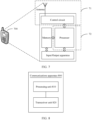
- FIG. 1 is a schematic diagram of a scenario of a communications system to which an embodiment of this application is applicable.
- the communications system 100 includes a network device 102 and a plurality of terminal devices (such as a terminal device 116 and a terminal device 122).
- the network device 102 may provide a communications service for the terminal device and access a core network.
- the terminal device accesses the network by searching for a synchronization signal, a broadcast signal, or the like that is sent by the network device, to communicate with the network, for example, perform uplink/downlink transmission.
- the network device 102 may include a plurality of antenna groups.
- Each antenna group may include a plurality of antennas.
- one antenna group may include antennas 104 and 106, another antenna group may include antennas 106 and 110, and an additional group may include antennas 112 and 114.
- FIG. 1 shows two antennas for each antenna group.
- each group may include more or fewer antennas.
- the network device 102 may additionally include a transmitter chain and a receiver chain, and a person of ordinary skill in the art may understand that both of them may include a plurality of components (for example, a processor, a modulator, a multiplexer, a demodulator, a demultiplexer, and an antenna) related to signal sending and receiving.
- the network device 102 may communicate with a plurality of terminal devices (for example, the terminal device 116 and the terminal device 122). However, it may be understood that the network device 102 may communicate with any quantity of terminal devices that are similar to the terminal device 116 or 122.
- the terminal device 116 communicates with the antennas 112 and 114.
- the antennas 112 and 114 send information to the terminal device 116 through a forward link 116, and receive information from the terminal device 116 through a reverse link 120.
- the terminal device 122 communicates with the antennas 104 and 106.
- the antennas 104 and 106 send information to the terminal device 122 through a forward link 124, and receive information from the terminal device 122 through a reverse link 126.
- the forward link 116 may use a frequency band different from that used by the reverse link 120, and the forward link 124 may use a frequency band different from that used by the reverse link 126.
- FDD frequency division duplex
- the forward link 116 and the reverse link 120 may use a same frequency band, and the forward link 124 and the reverse link 126 may use a same frequency band.
- Each antenna group and/or area designed for communication is referred to as a sector of the network device 102.
- an antenna group may be designed to communicate with a terminal device in the sector within coverage of the network device 102.
- a transmit antenna of the network device 102 may improve signal-to-noise ratios of the forward links 116 and 124 through beamforming.
- a manner in which the network device 102 sends, through beamforming, a signal to the terminal devices 116 and 122 that are randomly distributed within related coverage causes less interference to a mobile device in a neighboring cell.
- the network device 102, the terminal device 116, or the terminal device 122 may be a wireless communications sending apparatus and/or a wireless communications receiving apparatus.
- the wireless communications sending apparatus may encode the data for transmission.
- the wireless communications sending apparatus may obtain (for example, generate, receive from another communications apparatus, or store in a memory) a particular quantity of data bits to be sent on a channel to the wireless communications receiving apparatus.
- the data bit may be included in a transport block (or a plurality of transport blocks) of the data, and the transport block may be segmented to generate a plurality of code blocks.
- the communications system 100 may be a public land mobile network PLMN network, a device-to-device (device to device, D2D) network, a machine-to-machine (machine to machine, M2M) network, or another network.
- PLMN public land mobile network
- D2D device to device
- M2M machine-to-machine
- FIG. 1 is merely an example of a simplified schematic diagram for ease of understanding, and the network may further include another network device that is not shown in FIG. 1 .
- the network device and the terminal device need to perform beam training to enable a receive beam and a transmit beam to match each other.
- beam training efficiency is relatively low.
- the existing standard stipulates that a terminal device can perform training in only one frequency band on the carrier at a time. Therefore, in this manner, the terminal device needs to perform a time division operation to complete training in a plurality of frequency bands on the carrier. Consequently, a training time is excessively long, and training efficiency is relatively low.
- an embodiment of this application provides a beam training method.
- the method at least one frequency band can be selected based on a capability of a terminal device to perform beam training, so that training efficiency can be improved.
- the terminal device may report capability indication information indicating the capability of the terminal device.
- the capability indication information may be used to indicate that the terminal device can support simultaneous beam training in a maximum of N frequency bands.
- the network device may select a plurality of frequency bands at a time based on the capability of the terminal device to simultaneously perform beam training.
- the quantity N, of frequency bands for simultaneous training, supported by the terminal device is greater than 1, beam training may be simultaneously performed between the network device and the terminal device in a plurality of frequency bands.
- the quantity of frequency bands for training is not reduced. Therefore, in this embodiment of this application, beam training efficiency can be improved while training accuracy can be ensured.
- a carrier indicates a frequency domain width occupied by an orthogonal frequency division multiplexing (orthogonal frequency division multiplexing, OFDM) symbol.
- a beam may also be referred to as a spatial domain filter
- a transmit beam may also be referred to as a spatial domain transmission filter
- a receive beam may also be referred to as a spatial domain receive filter.
- the beam in the embodiments of this application may be a wide beam, a narrow beam, or a beam of another type.
- a beam forming technology may be a beamforming technology or another technical means.
- the beamforming technology may be specifically a digital beamforming technology, an analog beamforming technology, or a hybrid digital/analog beamforming technology.
- a transmit end may send same information or different pieces of information by using different beams.
- a plurality of beams having a same or similar communication feature may be considered as one beam.
- One beam may include one or more antenna ports, to transmit a data channel, a control channel, a sounding signal, and the like.
- the transmit beam may be signal strength distribution formed in different directions in space after a signal is transmitted by using an antenna
- the receive beam may be signal strength distribution in different directions in space of a radio signal received from an antenna.
- one or more antenna ports forming one beam may also be considered as one antenna port set.
- the beam may be represented as a spatial domain filter (spatial filter) in a protocol.
- Beam training indicates a process in which the network device and the terminal device search for a receive/transmit beam pair that matches each other.
- Beam training refers to descriptions in an existing standard. Details are not described again in the embodiments of this application.
- performing beam training in a frequency band may also be referred to as performing beam management, beam tracking, or the like in the frequency band.
- a process of performing beam training in the frequency band may indicate a process of searching for a best receive/transmit beam pair in the frequency band by a receive end and a transmit end.
- the terminal device measures a transmit beam of the network device, and feeds back a reference signal received power (reference signal receiving power, RSRP), for example, a layer 1 reference signal received power (layer 1 reference signal received power, L1-RSRP) in NR.
- RSRP reference signal receiving power
- L1-RSRP layer 1 reference signal received power
- the base station uses a transmit beam corresponding to a maximum value of the L1-RSRP as a best transmit beam and feeds back the transmit beam.
- the terminal device calculates an L1-RSRP by changing a receive beam of the terminal device, to select a receive beam corresponding to a maximum value of the L1-RSRP as a best receive beam corresponding to a transmit beam.
- the foregoing best transmit beam and best receive beam constitute the foregoing best transmit and receive beam pair, to perform subsequent channel state information CSI measurement and/or data transmission.
- FIG. 2 is a schematic flowchart of a beam training method according to an embodiment of the present invention.
- the method shown in FIG. 2 is described from a perspective of interaction between a network device and a terminal device.
- FIG. 2 shows a method in this embodiment of this application in a downlink transmission scenario.
- the method 200 shown in FIG. 2 includes the following steps: 210.
- a terminal device generates capability indication information, where the capability indication information is used to indicate that the terminal device can support simultaneous beam training in a maximum of N frequency bands, and N is an integer greater than or equal to 1.
- the terminal device may generate the capability indication information based on a default configuration, for example, but not limited to, a capability of receiving beams by the terminal device, an RSRP calculation capability, and the like. This embodiment of this application is not limited thereto.
- the frequency band indicates a segment of continuous frequency domain resources.
- the frequency band may be a bandwidth part (bandwidth part, BWP).
- the BWP may be understood as a segment of continuous frequency bands.
- the frequency band includes at least one continuous sub-band.
- Each bandwidth part may correspond to a group of numerologies (numerology), including, for example, but not limited to, a subcarrier spacing, a cyclic prefix (cyclic prefix, CP) length, a transmission time interval (transmission time interval, TTI), a quantity of symbols (symbol), a resource block (resource block, RB) location, a slot length, and a frame format.
- numerologies number of numerologies
- different bandwidth parts may correspond to different numerologies.
- the bandwidth part refer to the current technology, for example, but not limited to, various proposals for NR. As the technology continuously develops, the foregoing definition may also change.
- the frequency band may alternatively be a beam tracking band (tracking band).
- the beam tracking band may include at least one subcarrier.
- the beam tracking band may include at least one resource block (resource block, RB) in frequency domain.
- the beam tracking band may include at least one precoding group (precoding resource group, PRG) in frequency domain.
- the beam tracking band may include at least one resource block group (resource block group, RBG) in frequency domain.
- only a signal used for beam training can be scheduled in the beam tracking band.
- only a signal and a control channel for example, a physical downlink control channel (physical downlink control channel, PDCCH)
- PDCCH physical downlink control channel
- signals used for beam training and scheduled between different beam tracking bands may be different.
- the frequency band is a BWP for description.
- this embodiment of this application is not limited thereto.
- the frequency band is a beam tracking band, refer to the description in which the frequency band is the BWP.
- the N frequency bands belong to a same carrier CC.
- the CC includes a frequency domain width occupied by one orthogonal frequency division multiplexing OFDM symbol.
- the terminal device on a same CC, on a same OFDM symbol, the terminal device expects (expect), by using capability indication information, to simultaneously perform beam training in different frequency bands (for example, BWPs).
- BWPs frequency bands
- the terminal device expects that a respective independent spatial domain filter (downlink spatial domain transmission filter) may be used in each BWP.
- Different downlink spatial domain filters or a same downlink spatial domain filter may be used for signals that are used for beam training and are transmitted in different BWPs.
- a same CC includes a BWP 1 and a BWP 2.
- the terminal device may report a capability of the terminal device by using the capability indication information.
- the terminal device expects that signals that are used for beam training and transmitted in the two BWPs may use different downlink spatial domain filters or a same downlink spatial domain filter.
- FIG. 3 shows merely an example in which one CC includes two BWPs.
- this embodiment of this application is not limited thereto.
- one CC may include a plurality of BWPs.
- one CC includes three BWPs, four BWPs, and the like.
- a signal used for beam training and transmitted in the frequency band may be at least one type of signal in the following signals: an aperiodic channel state information reference signal (aperiodic channel state information reference signal, A-CSI-RS), a periodic channel state information reference signal (periodic channel state information reference signal, P-CSI-RS), a semi-persistent channel state information reference signal (semi-persistent channel state information reference signal, SP-CSI-RS), and a synchronization signal/broadcast channel block (synchronous signal/physical broadcast channel (PBCH) block, SSB).
- A-CSI-RS aperiodic channel state information reference signal
- P-CSI-RS periodic channel state information reference signal
- SP-CSI-RS semi-persistent channel state information reference signal
- SP-CSI-RS semi-persistent channel state information reference signal
- SSB synchronization signal/broadcast channel block
- the A-CSI-RS, the P-CSI-RS, and the SP-CSI-RS may be collectively referred to as a channel state information reference signal (channel state information reference signal, CSI-RS).
- the signal used for beam training and transmitted in the frequency band may be at least one type of signal in a CSI-RS and an SSB.
- the signal used for beam training in this embodiment of this application may alternatively be another signal.
- This embodiment of this application is not limited thereto.
- the capability indication information in this embodiment of this application is described in the following two cases.
- Case 1 For different signals, in this embodiment of this application, the terminal device may not distinguish between specific signal types and report only one capability. In other words, signals used for beam training and transmitted in the frequency band all correspond to the same capability.
- the "capability" in this specification is a capability that the terminal device can support simultaneous beam training in a plurality of frequency bands.
- One capability corresponds to one capability value.
- a capability value N corresponding to one capability indicates that the terminal device can support simultaneous beam training in a maximum of N frequency bands.
- Case 2 The terminal device distinguishes between signal types, and needs to report a plurality of capabilities for a plurality of signals, where different signals of the plurality of signals may correspond to a same capability value or different capability values.
- capability values corresponding to the plurality of capabilities corresponding to the plurality of signals may be the same or may be different.
- a capability value corresponding to the first signal may indicate a maximum quantity, of frequency bands (herein, the frequency band is a frequency band in which the first signal is transmitted) for simultaneous beam training, supported by the terminal device.
- the case 1 is a case in which the terminal device does not distinguish between specific signal types, and reports only one capability.
- a signal transmitted in each of a plurality of frequency bands in which beam training is simultaneously performed is not limited.
- the signal transmitted in each frequency band may be any one or more of an A-CSI-RS, a P-CSI-RS, an SP-CSI-RS, and an SSB.
- the signal transmitted in each frequency band may be one or both of a CSI-RS and an SSB. This embodiment of this application is not limited thereto.
- a capability reported by the terminal device is not limited by a signal type. After reporting the capability indication information, the terminal device does not expect that a quantity of scheduled BWPs in which simultaneous L1-RSRP measurement and calculation are performed exceeds the capability value N. That is, the maximum quantity of BWPs expected by the terminal device to simultaneously perform L1-RSRP measurement and calculation is N.
- each of a plurality of frequency bands in which beam training is simultaneously performed corresponds to one beam, and two different frequency bands in the plurality of frequency bands may correspond to different beams or may correspond to a same beam.
- This embodiment of this application is not limited thereto.
- all CSI-RS resources (CSI-RS resource) in one CSI-RS resource set (CSI-RS resource set) or all CSI-RS resources (CSI-RS resource) in a same CSI-RS resource setting (CSI-RS resource setting) use a same beam (or referred to as a downlink spatial domain filter).
- each BWP may include at least one resource block (resource block, RB).
- resource block resource block
- the BWP 1 includes four RBs, the signal 1 is carried on two RBs, and the signal 2 is carried on the other two RBs; the BWP 2 includes four RBs, and the signal 3 is carried on the four RBs.
- the signal 1 and the signal 2 belong to a same CSI-RS resource, a same CSI-RS resource set, or a same CSI-RS resource setting.
- the signal 1 and the signal 2 correspond to a same beam.
- both of the signal 1 and the signal 2 correspond to a beam 1.
- a beam 2 corresponding to the signal 3 may be the same as or different from the beam 1.
- the signal 1 and the signal 2 may be signals of a same type, for example, CSI-RSs of a same type.
- the CSI-RSs of the same type are P-CSI-RSs, A-CSI-RSs, or SP-CSI-RSs.
- the signal 3 may be any type of signal used for beam training described above, for example, a P-CSI-RS, an A-CSI-RS, or an SP-CSI-RS.
- the capability indication information may include a value of N. That is, the capability indication information includes the capability value N of the terminal device.
- the terminal device may directly report the capability value N by using the capability indication information.
- the network device may directly determine the capability value of the terminal device based on obtained capability indication information. Further, the network device may determine a quantity of frequency bands for simultaneous beam training. It should be understood that the quantity, of frequency bands for simultaneous beam training, determined by the network device is usually less than or equal to a capability value reported by the terminal device.
- the terminal device reports the capability value, so that the network device can directly determine a capability of the terminal device based on the capability value, and no additional calculation process is required. This can reduce calculation overheads.
- the capability indication information includes first indication information and second indication information.
- the first indication information is used to indicate a maximum quantity x, of frequency bands that are simultaneously in an active state, supported by the terminal device.
- the second indication information is used to indicate a maximum quantity y, of analog beams, panels, or simultaneous spatial domain receive filters (simultaneous spatial domain receive filters) that are used for receiving, supported by the terminal device.
- x and y are used to determine a value of N.
- x may be a maximum quantity, of frequency bands for simultaneous channel state information (CSI) measurement, supported by the terminal device and/or a maximum quantity, of frequency bands used for data transmission, supported by the terminal device.
- CSI channel state information
- the terminal device reports x and y by using the capability indication information, to indirectly indicate the capability value of the terminal device. That is, the terminal device indirectly reports the capability value by using the capability indication information.
- the network device needs to calculate and determine a specific capability value of the terminal device based on capability information reported by the terminal device, that is, x and y.
- N is a smaller value in x and y.
- the terminal device may further report, by using the capability indication information, whether a single spatial domain receive filter (single spatial domain receive filter) is supported.
- the terminal device may indirectly report a capability of the terminal device by using existing information, and does not need to specially report the capability value of the terminal device. This can reduce signaling overheads and save network resources.
- the following describes the case 2 in which the terminal device needs to distinguish between signal types to report a plurality of capabilities.
- a capability reported by the terminal device is limited by a signal type.
- the terminal device separately reports capabilities for different signals, or uses some signals as a set, considers the signals as a whole, and reports one capability.
- the capability indication information is specifically used to indicate that the terminal device can support simultaneous beam training in a maximum of n i frequency bands for an i th signal set in m signal sets, where i represents a number of a signal set, i traverses values 1, 2, ..., and m, m represents a quantity of the signal sets, n i is an integer greater than or equal to 1, m is an integer greater than or equal to 1, N is a maximum value of n i , the i th signal set includes at least one signal, and a maximum quantity, of frequency bands for beam training, that can be supported by the terminal device for each signal in the at least one signal is n i .
- n i may represent a maximum quantity of frequency bands used by the terminal device to simultaneously perform beam training based on each signal in the i th signal set.
- the i th signal includes a signal 1 and a signal 2.
- a maximum quantity of frequency bands used by the terminal device to simultaneously perform beam training based on the signal 1 is n i
- a maximum quantity of frequency bands used by the terminal device to simultaneously perform beam training based on the signal 2 is n i .
- the i th signal set may be considered as a whole, and n i may also represent a maximum quantity of frequency bands used by the terminal device to simultaneously perform beam training based on all signals in the i th signal set.
- the i th signal includes the signal 1 and the signal 2.
- a maximum quantity of frequency bands used by the terminal device to simultaneously perform beam training based on the i th signal set is n i .
- a sum of all frequency bands carrying the signals in the i th signal set is not greater than n i .
- frequency bands corresponding to all the sets belong to a same CC.
- the terminal device may divide a plurality of signals used for beam training into at least one signal set based on types of signals used for beam training, and then set one capability value for each signal set.
- Signals in one signal set have a same attribute or similar attributes.
- the signals are all CSI-RSs, and the like.
- capability values corresponding to different signal sets may be the same or may be different. This embodiment of this application is not limited thereto.
- the terminal device may classify signals whose capability values are equal or close to each other into a signal set based on capability values corresponding to the signals used for beam training, and then set a capability value for each signal set.
- different signal sets may correspond to different capability values.
- the terminal device may also divide the signals used for beam training into at least one signal set in another manner. This embodiment of this application is not limited thereto.
- different signal sets in the m signal sets include different signals
- the i th signal set includes at least one type of signal in a channel state information reference signal CSI-RS and a synchronization signal/broadcast channel block SSB.
- the CSI-RS includes at least one type of signal in an aperiodic channel state information reference signal A-CSI-RS, a periodic channel state information reference signal P-CSI-RS, and a semi-persistent channel state information reference signal SP-CSI-RS.
- the i th signal set includes at least one type of signal in the A-CSI-RS, the P-CSI-RS, the SP-CSI-RS, and the SSB.
- a set of signals used for beam training may be referred to as a preset signal set.
- the preset signal set includes an A-CSI-RS, a P-CSI-RS, an SP-CSI-RS, and an SSB.
- the preset signal set includes a CSI-RS and an SSB.
- the preset signal set in this embodiment of this application may represent a set of signals used for beam training in an actual beam training process.
- the signals used for beam training during actual application are not limited to the foregoing several types of signals listed in this embodiment of this application.
- signals (a preset signal set) used for beam training may include only some of the foregoing signals, or signals (a preset signal set) used for beam training may further include another signal. This embodiment of this application is not limited thereto.
- the preset signal set may also be referred to as a signal set, a first set, or the like used for beam training. This embodiment of this application is not limited thereto.
- signals in the m signal sets may include all signals in the preset signal set, or may include only some signals in the preset signal set. This embodiment of this application is not limited thereto.
- each set includes only one signal.
- a capability is reported for each signal by the network device.
- a capability corresponding to one signal indicates a maximum quantity, of frequency bands for simultaneous beam training, that can be supported by the terminal device for the signal.
- the capability indication information includes a value of n i . That is, the capability indication information includes m capability values corresponding to the m signal sets.
- the i th signal set may also be referred to as an i th signal. That is, when the network device reports one capability for each signal, the capability indication information may include m capability values corresponding to m signals.
- a first signal set includes an SSB
- a second signal set includes a P-CSI-RS
- a third signal set includes an SP-CSI-RS
- a fourth signal set includes an A-CSI-RS.
- the capability indication information includes values of n 1 to n 4 .
- the capability indication information is used to indicate:
- the terminal device after reporting the capability indication information, during beam training, the terminal device:
- the terminal device expects (expect):
- capability values corresponding to different signals may be the same or different.
- the terminal device reports one capability value for each signal.
- the terminal device may report a capability value of only one signal for the some signals, and indicate that capability values of remaining signals are equal to the capability value of the signal.
- there are four types of signals namely, a first signal to a fourth signal.
- the terminal device reports only capability values corresponding to the first signal, the third signal, and the fourth signal, and indicates that the capability value corresponding to the second signal is equal to the capability value corresponding to the first signal. In this way, only one capability value is reported for a plurality of signals whose capability values are equal in this embodiment of this application. This reduces signaling overheads and improves network performance.
- the first signal and the second signal may be considered as a set
- the third signal may be considered as a set
- the fourth signal may be considered as a set.
- m 3.
- the terminal device needs to indicate, by using the capability indication information, only three capability values, that is, the capability value corresponding to the first signal and the second signal (the first signal set), the capability value corresponding to the third signal (the second signal set), and the capability value corresponding to the fourth signal (the third signal set).
- one signal set, for example, the first signal set, in the m signal sets includes a P-CSI-RS, an SP CSI-RS, and an A CSI-RS.
- Signals in the first signal set are all CSI-RSs.
- the capability indication information may be specifically described as being used to indicate that the terminal device can support, for the CSI-RS (the first signal set), simultaneous beam training in a maximum of n 1 frequency bands.
- the terminal device after reporting the capability indication information, during beam training, the terminal device does not expect that a quantity of scheduled BWPs in which simultaneous CSI-RS-based L1-RSRP measurement and calculation are performed exceeds n 1 . In other words, the terminal device expects (expect) that the quantity of BWPs in which simultaneous CSI-RS-based L1-RSRP measurement and calculation are performed is not greater than n 1 .
- n 1 herein may indicate that for each type of CSI-RS, a maximum quantity of frequency bands used by the terminal device to simultaneously perform beam training is n 1 . Further, n 1 may further indicate that specific CSI-RS types are not distinguished, CSI-RSs of all types are considered as a set, and a maximum quantity of frequency bands used by the terminal device to simultaneously perform beam training is n 1 . In other words, a sum of all frequency bands carrying CSI-RSs (where the CSI-RS may be a P-CSI-RS, an SP CSI-RS, or an A CSI-RS) during beam training of the terminal device is not greater than n 1 .
- one signal set, such as the first signal set, in the m signal sets includes a P-CSI-RS and an SP CSI-RS.
- Signals in the first signal set are all periodic CSI-RSs.
- the capability indication information may be specifically described as being used to indicate that the terminal device can support, for the periodic CSI-RS (the first signal set), simultaneous beam training in a maximum of n 1 frequency bands.
- the terminal device after reporting the capability indication information, during beam training, the terminal device does not expect that a quantity of scheduled BWPs in which simultaneous periodic CSI-RS-based L1-RSRP measurement and calculation are performed exceeds n 1 . In other words, the terminal device expects (expect) that the quantity of BWPs in which simultaneous periodic CSI-RS-based L1-RSRP measurement and calculation are performed is not greater than n 1 .
- n 1 herein may indicate that for each type of periodic CSI-RS, a maximum quantity of frequency bands used by the terminal device to simultaneously perform beam training is n 1 . Further, n 1 may further indicate that specific periodic CSI-RS types are not distinguished, periodic CSI-RSs of all types are considered as a set, and a maximum quantity of frequency bands used by the terminal device to simultaneously perform beam training is n 1 . In other words, a sum of all frequency bands carrying periodic CSI-RSs (where the periodic CSI-RS may be a P-CSI-RS or an SP CSI-RS) during beam training of the terminal device is not greater than n 1 .
- case 1 may be considered as a special case of the case 2.
- case 2 is the same as the case 1.
- the capability indication information may include only a capability value corresponding to the set, for example, n 1 .
- the capability indication information includes first indication information and second indication information.
- the first indication information is used to indicate a maximum quantity x, of frequency bands that are simultaneously in an active state, supported by the terminal device.
- the second indication information is used to indicate a maximum quantity y, of analog beams, panels, or spatial domain receive filters that are simultaneously used for receiving, supported by the terminal device.
- x and y are used to determine a value of n 1 . Both x and y are integers greater than or equal to 1. In this case, reference may be made to the description in the foregoing case 1, provided that N above is replaced with n 1 . Details are not described herein again.
- the signals in the m signal sets include some signals in the preset signal set.
- the m signal sets include some signals in the preset signal set in total.
- a quantity of frequency bands corresponding to each of other signals than the some signals in the preset signal set is equal to n i corresponding to a signal set in which a signal with a highest priority in the some signals is located.
- a quantity of frequency bands corresponding to one signal indicates a maximum quantity of frequency bands used by the terminal device to simultaneously perform beam training based on the signal.
- sequences of priorities of the signals are an SSB, a P-CSI-RS, an SP-CSI-RS and an A-CSI-RS in descending order.
- a capability value corresponding to the SSB is equal to a capability value corresponding to the P-CSI-RS.
- capability values corresponding to the SSB and the P-CSI-RS are equal to a capability value corresponding to the SP-CSI-RS.
- signals in the m signal sets do not include the SSB, the P-CSI-RS, and the SP-CSI-RS, but include the A-CSI-RS, capability values corresponding to the SSB, the P-CSI-RS, the SP-CSI-RS are equal to a capability value corresponding to the A-CSI-RS.
- a case in which the signals in the m signal sets do not include another signal is similar to a case in which the signals in the m signal sets do not include the SSB. Cases are not listed one by one herein.
- the capability value corresponding to the signal may be determined based on a priority of the signal.
- this embodiment of this application is not limited thereto.
- the capability value corresponding to the SSB may alternatively be one of the following two values: a capability value corresponding to a CSI-RS, and a capability value corresponding to the periodic CSI-RS.
- the capability value corresponding to the A-CSI-RS may be a capability value corresponding to the periodic CSI-RS.
- the capability indication information is used to indicate capability values of only some signals. This can reduce signaling overheads.
- the terminal device sends the capability indication information.
- the network device receives the capability indication information.
- the network device indicates, based on the capability indication information, the terminal device to perform beam training.
- the network device may determine at least one frequency band based on the received capability indication information, and indicate the terminal device to perform beam training in the at least one frequency band.
- a quantity of the at least one frequency band determined by the network device is less than or equal to the capability value indicated by the capability indication information reported by the terminal device.
- the network device generates indication information (where the indication information may also be referred to as configuration information) based on the capability indication information, and sends the indication information to the terminal device, to indicate the terminal device to perform beam training.
- indication information (where the indication information may also be referred to as configuration information) based on the capability indication information, and sends the indication information to the terminal device, to indicate the terminal device to perform beam training.
- the indication information may be used to indicate a type of a signal used for beam training.
- the signal used for beam training is a CSI-RS (where for example, the CSI-RS may be a P-CSI-RS, an SP-CSI-RS, or an A-CSI-RS) or an SSB.
- the indication information may be further used to indicate at least one of the following information: a quantity of frequency bands used by the terminal device to simultaneously perform beam training, indexes of the frequency bands used by the terminal device to simultaneously perform beam training, identifiers of the frequency bands used by the terminal device to simultaneously perform beam training, a time-frequency resource location of the signal used for beam training, a time domain resource offset (offset) of the signal used for beam training, a periodicity of the signal used for beam training, and the like.
- the indication information may further indicate the terminal device not to report a measurement result of a beam.
- the indication information may further indicate the terminal device to report a measurement result.
- the indication information may indicate the terminal device to report at least one of the following information: information such as L1-RSRP of a signal, an index (index) of a signal, and an index (index) of a frequency band.
- the index of the signal may be, for example, a channel state information reference signal resource indicator (CSI-RS Resource Indicator, CRI).
- CRI channel state information reference signal resource indicator
- the at least one frequency band is L frequency bands.
- the network device indicates, based on the capability indication information, the terminal device to simultaneously perform beam training in the L frequency bands, where L is an integer less than or equal to N.
- the terminal device calculates layer 1 reference signal received powers L1-RSRPs of signals transmitted in the L frequency bands or on L beams.
- a specific value of L may be determined by the network device based on factors such as a capability of the network device and/or a measurement requirement of the terminal device.
- the capability of the network device may indicate a capability that can be supported by the network device and that is of a quantity of BWPs in which beam training can be simultaneously performed.
- the measurement requirement of the terminal device may indicate a requirement that is of a quantity of BWPs needing to be used by the terminal device to simultaneously perform training and that is determined by the network device based on a factor such as a network status. It should be understood that, definitions of a capability of the network device and a measurement requirement of the terminal device in the following are similar thereto, and are not described one by one in the following.
- a signal transmitted in each of the L frequency bands is not limited, and the signal transmitted in each frequency band may include at least one signal in the preset signal set.
- the at least one frequency band includes z frequency bands.
- the network device indicates, based on the capability indication information, the terminal device to simultaneously perform beam training in the z frequency bands N.
- the terminal device calculates L1-RSRPs of first signals simultaneously transmitted in the z frequency bands, where z is an integer not greater than n i , and the first signal is any signal in the i th signal set.
- the network device and the terminal device simultaneously perform beam training in z frequency bands.
- a signal used for beam training may not be limited to the signal. Therefore, for all signals used for beam training, the at least one frequency band may be P frequency bands.
- the network device and the terminal device simultaneously perform beam training in the P frequency bands.
- the P frequency bands include the z frequency bands in which the first signal in the i th signal set is simultaneously transmitted, z is an integer not greater than n i , and the first signal is any signal in the i th signal set.
- a total quantity of frequency bands carrying the signals in the i th signal set is not greater than n i .
- a total quantity of frequency bands occupied by all signals in the i th signal set is less than or equal to n i .
- a quantity of frequency bands in which the signal is transmitted is less than or equal to a capability value corresponding to the signal.
- a specific value of P and/or z may be determined by the network device based on factors such as a capability of the network device and/or a measurement requirement of the terminal device. This embodiment of this application is not limited thereto.
- P is less than or equal to N. That is, a value of P is less than or equal to a maximum capability value N corresponding to a signal.
- P may also be greater than N.
- a maximum value of P is n 1 +n 2 +...+n m .
- the terminal device reports the capability indication information to the network device, so that the network device can simultaneously perform beam training in a plurality of frequency bands based on a capability of the terminal device. In this way, beam training efficiency can be improved in this embodiment of this application.
- beam training in this embodiment of this application may include beam training in downlink transmission, for example, training of a downlink transmit beam of the network device and/or a downlink receive beam of the terminal device.
- beam training in this embodiment of this application may also include beam training in uplink transmission, for example, training of an uplink receive beam of the network device and/or an uplink transmit beam of the terminal device. This embodiment of this application is not limited thereto.
- actual beam training may include but is not limited to the following process:
- the terminal device may first measure a signal sent by the network device in at least one frequency band, then calculate and search for a better transmit beam that is of the network device and that corresponds to each frequency band, and finally, feed back information about the better transmit beam in each frequency band to the network device.
- beam training may be simultaneously performed, and the terminal device independently measures and calculates an L1-RSRP for each frequency band (for example, a BWP) in the plurality of frequency bands. That is, in this embodiment of this application, the terminal device performs L1-RSRP measurement and calculation based on each BWP.
- the terminal device may feed back a beam training signal index (for example, a CRI) and/or an L1-RSRP in each BWP, so that the network device selects a best transmit beam or best transmit beams in one or more BWPs.
- a beam training signal index for example, a CRI
- the terminal device may determine, based on an L1-RSRP in each BWP, a best receive beam corresponding to a transmit beam in each BWP. Further, the terminal device may further feed back a beam training signal index (for example, a CRI) and/or an L1-RSRP in each BWP in which a downlink receive beam is trained. Based on downlink transmit beam training and/or downlink receive beam training, the network device may select at least one BWP, to simultaneously perform subsequent channel state information CSI measurement and/or data transmission by using a best transmit beam and a best receive beam in each selected BWP.
- a beam training signal index for example, a CRI
- the network device may select at least one BWP, to simultaneously perform subsequent channel state information CSI measurement and/or data transmission by using a best transmit beam and a best receive beam in each selected BWP.
- the network device may select one or more better frequency bands (for example, BWPs) to communicate with the terminal device by using a beam obtained through training.
- a network side may configure the one or more BWPs for the terminal device by using radio resource control (radio resource control, RRC) signaling, downlink control information (downlink control information, DCI), or a media access control control element (media access control element, MAC CE).
- RRC radio resource control
- DCI downlink control information
- MAC CE media access control element
- the network device may send a reference signal to the terminal device by using a beam or beams in the one or more BWPs, to perform channel measurement, then receives channel state information (channel state information, CSI) fed back by the terminal device and/or CSI obtained through channel heterogeneity, and then sends downlink data in the one or more BWPs based on the CSI.
- channel state information channel state information, CSI
- the communication method provided by this application is not limited to downlink transmission, and may also be applicable to uplink transmission.
- This application imposes no special limitation on a signal for beam training.
- the reference signal may be, for example, a channel state information reference signal (channel state information reference signal, CSI-RS) and an SSB;
- a signal used for beam training may be another signal such as a sounding reference signal (sounding reference signal, SRS).
- SRS sounding reference signal
- the signals used for beam training listed above are merely an example for description, but should not constitute any limitation on this application.
- This application does not exclude a possibility of using another signal to implement beam training.
- this application does not exclude a possibility of defining another signal used for uplink or downlink beam training in an existing protocol (for example, an LTE protocol or an NR protocol) or a future protocol.
- the foregoing describes, with reference to FIG. 2 , a case in which the terminal device reports a capability of the terminal device, and a method in which the network device determines, based on the capability of the terminal device, to simultaneously perform beam training in a plurality of frequency bands.
- the first indication information is used to indicate a quantity M of frequency bands in which the terminal device can simultaneously perform beam training, and M is an integer greater than or equal to 1.
- frequency band in this embodiment of this application, refer to the foregoing description in FIG. 2 . Details are not described herein again.
- M represents a maximum quantity of frequency bands in which the terminal device can simultaneously perform beam training.
- the first indication information is used to indicate the maximum quantity M of frequency bands in which the terminal device can simultaneously perform beam training.
- a quantity of frequency bands in which training is simultaneously performed may be less than or equal to M.
- M represents a quantity of frequency bands used when the terminal device performs beam training.
- the first indication information is used to indicate the quantity M of frequency bands in which the terminal device simultaneously performs beam training.
- the terminal device simultaneously performs beam training in the M frequency bands. That is, the network device simultaneously sends, in the M frequency bands, a signal used for beam training, to simultaneously train beams in the M frequency bands.
- the first indication information is generated by the network device based on the capability indication information reported by the terminal device.
- the method further includes: The terminal device sends the capability indication information to the network device, where the capability indication information is used to indicate that the terminal device can support simultaneous beam training in a maximum of N frequency bands, and N is an integer greater than or equal to 1.
- the network device may determine, based on the capability indication information of the terminal device, a capability of the terminal device to support a quantity of frequency bands for simultaneous beam training. Further, the network device determines M based on factors such as a capability of the network device and/or a measurement requirement of the terminal device, and generates the first indication information.
- the first indication information is generated by the network device based on a network status, for example, based on factors such as a capability of the network device and/or a measurement requirement of the terminal device.
- the network device sends the first indication information to the terminal device.
- the terminal device receives the first indication information.
- the network device and the terminal device perform beam training based on the first indication information.
- the network device and the terminal device simultaneously perform beam training in M' frequency bands.
- the terminal device simultaneously calculates L1-RSRPs of signals transmitted in the M' frequency bands, where M' is an integer less than or equal to M.
- a specific value of M' may be determined by the network device based on factors such as a capability of the network device and/or a measurement requirement of the terminal device. This embodiment of this application is not limited thereto.
- M represents a quantity of frequency bands used when the terminal device performs beam training
- the network device and the terminal device simultaneously perform beam training in the M frequency bands.
- beam training may be simultaneously performed between the network device and the terminal device in a plurality of frequency bands, so that beam training efficiency can be improved in this embodiment of this application.
- sequence numbers of the foregoing processes do not mean execution sequences in various embodiments of this application.
- the execution sequences of the processes should be determined according to functions and internal logic of the processes, and should not be construed as any limitation on the implementation processes of the embodiments of this application.
- FIG. 5 is a schematic structural diagram of a communications apparatus according to an embodiment of this application.
- the communications apparatus 500 may include: a processing unit 510 and a transceiver unit 520.
- the processing unit is configured to generate capability indication information, where the capability indication information is used to indicate that the communications apparatus can support simultaneous beam training in a maximum of N frequency bands, and N is an integer greater than or equal to 1; and the transceiver unit is configured to send the capability indication information.
- the processing unit is further configured to simultaneously calculate L1-RSRPs in L frequency bands, where L is an integer less than or equal to N.
- the capability indication information is specifically used to indicate that the communications apparatus can support simultaneous beam training in a maximum of n i frequency bands for an i th signal set in m signal sets, where i represents a number of a signal set, i traverses values 1, 2, ..., and m, m represents a quantity of the signal sets, n i is an integer greater than or equal to 1, m is an integer greater than or equal to 1, N is a maximum value of n i , the i th signal set includes at least one signal, and a maximum quantity, of frequency bands for beam training, that can be supported by the communications apparatus for each signal in the at least one signal is n i .
- the processing unit is further configured to calculate L1-RSRPs of first signals simultaneously transmitted in z frequency bands, where z is an integer not greater than n i , and the first signal is any signal in the i th signal set.
- different signal sets in the m signal sets include different signals
- the i th signal set includes at least one type of signal in a channel state information reference signal CSI-RS and a synchronization signal/broadcast channel block SSB.
- the CSI-RS includes at least one type of signal in an aperiodic channel state information reference signal A-CSI-RS, a periodic channel state information reference signal P-CSI-RS, and a semi-persistent channel state information reference signal SP-CSI-RS.
- the capability indication information includes a value of n i .
- the capability indication information includes first indication information and second indication information.
- the first indication information is used to indicate a maximum quantity x, of frequency bands that are simultaneously in an active state, supported by the terminal device.
- the second indication information is used to indicate a maximum quantity y, of analog beams, panels, or spatial domain receive filters that are simultaneously used for receiving, supported by the terminal device.
- x and y are used to determine a value of n 1 . Both x and y are integers greater than or equal to 1.
- n 1 is a smaller value in x and y.
- the frequency band is a bandwidth part BWP or a beam tracking band.
- the N frequency bands belong to a same carrier CC.
- the CC includes a frequency domain width occupied by one orthogonal frequency division multiplexing OFDM symbol.
- the communications apparatus 500 provided in this application corresponds to the process performed by the terminal device in the method embodiment of FIG. 3 .
- functions of the units/modules in the communications apparatus refer to the foregoing descriptions. Details are not described herein again.
- the terminal device reports the capability indication information to the network device, so that the network device can simultaneously perform beam training in a plurality of frequency bands based on a capability of the terminal device. In this way, beam training efficiency can be improved in this embodiment of this application.
- FIG. 6 is a schematic structural diagram of a communications apparatus according to an embodiment of this application.
- the communications apparatus 600 may include: a processing unit 610 and a transceiver unit 620.
- the transceiver unit is configured to receive first indication information, where the first indication information is used to indicate a quantity M of frequency bands in which the communications apparatus can simultaneously perform beam training, and M is an integer greater than or equal to 1; and the processing unit is configured to perform beam training based on the first indication information.
- the transceiver unit is further configured to send capability indication information to a network device, where the capability indication information is used to indicate that the communications apparatus can support simultaneous beam training in a maximum of N frequency bands, N is an integer greater than or equal to 1, the first indication information is generated by the network device based on the capability indication information, and M ⁇ N.
- M represents a maximum quantity of frequency bands in which the communications apparatus simultaneously performs beam training.
- M represents a quantity of frequency bands used when the communications apparatus performs beam training.
- the processing unit is configured to simultaneously calculate layer 1 reference signal received powers L1-RSRPs of signals transmitted in M' frequency bands, where M' is an integer less than or equal to M.
- the communications apparatus 600 provided in this application corresponds to the process performed by the terminal device in the method embodiment of FIG. 4 .
- functions of the units/modules in the communications apparatus refer to the foregoing descriptions. Details are not described herein again.
- beam training may be simultaneously performed between the network device and the terminal device in a plurality of frequency bands, so that beam training efficiency can be improved in this embodiment of this application.
- the communications apparatus in FIG. 5 and FIG. 6 may be a terminal device, or may be a chip or an integrated circuit installed in a terminal device.
- the communications apparatus is a terminal device.
- FIG. 7 is a schematic structural diagram of a terminal device according to an embodiment of this application.
- the terminal device is a mobile phone.
- FIG. 7 shows only main components of the terminal device.
- the terminal device 700 shown in FIG. 7 includes a processor, a memory, a control circuit, an antenna, and an input/output apparatus.
- the processor is mainly configured to process a communications protocol and communications data, control the entire terminal device, execute a software program, and process data of the software program, for example, configured to support the terminal device in performing the actions described in the foregoing method embodiments.
- the memory is configured to store the software program and data.
- the control circuit is mainly configured to perform conversion between a baseband signal and a radio frequency signal, and process the radio frequency signal.
- a combination of the control circuit and the antenna may be referred to as a transceiver, mainly configured to send and receive a radio frequency signal in an electromagnetic wave form.
- the input/output apparatus such as a touchscreen, a display screen, or a keyboard, is mainly configured to receive data entered by a user and output data to the user.
- the processor may read the software program in a storage unit, explain and execute an instruction of the software program, and process the data of the software program.
- the processor outputs a baseband signal to a radio frequency circuit.
- the radio frequency circuit After performing radio frequency processing on the baseband signal, the radio frequency circuit sends a radio frequency signal in a form of an electromagnetic wave through the antenna.
- the radio frequency circuit receives a radio frequency signal through the antenna, converts the radio frequency signal into a baseband signal, and outputs the baseband signal to the processor.
- the processor converts the baseband signal into data, and processes the data.
- FIG. 7 shows only one memory and only one processor.
- the terminal device may include a plurality of processors and a plurality of memories.
- the memory may also be referred to as a storage medium, a storage device, or the like. This is not limited in this embodiment of this application.
- the processor may include a baseband processor and a central processing unit.
- the baseband processor is mainly configured to process the communications protocol and the communications data.
- the central processing unit is mainly configured to control the entire terminal device, execute the software program, and process the data of the software program. Functions of the baseband processor and the central processing unit may be integrated into the processor in FIG. 7 .
- a person skilled in the art may understand that the baseband processor and the central processing unit each may be an independent processor, and are interconnected by using a technology such as a bus.
- the terminal device may include a plurality of baseband processors to adapt to different network standards, the terminal device may include a plurality of central processing units to improve a processing capability of the terminal device, and the components of the terminal device may be connected by using various buses.
- the baseband processor may also be expressed as a baseband processing circuit or a baseband processing chip.
- the central processing unit may also be expressed as a central processing circuit or a central processing chip.
- a function of processing the communications protocol and the communications data may be built in the processor, or may be stored in the storage unit in a form of software program.
- the processor executes the software program to implement a baseband processing function.
- an antenna having a transceiver function and a control circuit may be considered as a transceiver unit 71 of the terminal device 700, for example, configured to support the terminal device in performing the transceiver function performed by the terminal device in FIG. 5 or FIG. 6 , for example, sending capability indication information and/or receiving a signal used for beam training.
- the processor having a processing function is considered as a processing unit 72 of the terminal device 700, and corresponds to the processing unit 510 in FIG. 5 or the processing unit 610 in FIG. 6 , for example, generates capability indication information and/or performs beam training, for example, calculates an L1-RSRP. As shown in FIG.
- the terminal device 700 includes the transceiver unit 71 and the processing unit 72.
- the transceiver unit may also be referred to as a transceiver, a transceiver machine, a transceiver apparatus, or the like.
- the transceiver unit corresponds to the transceiver unit 520 in FIG. 5 or the transceiver unit 620 in FIG. 6 .
- a device configured to implement a receiving function in the transceiver unit 71 may be considered as a receiving unit
- a device configured to implement a sending function in the transceiver unit 71 may be considered as a sending unit.
- the transceiver unit 71 includes the receiving unit and the sending unit.
- the receiving unit may also be referred to as a receiver machine, an input port, a receiver circuit, or the like.
- the sending unit may be referred to as a transmitter machine, a transmitter, a transmitter circuit, or the like.
- the processing unit 72 may be configured to execute an instruction stored in the memory, to control the transceiver unit 71 to receive a signal and/or send a signal to complete a function of the terminal device in the foregoing method embodiments.
- a function of the transceiver unit 71 may be implemented by using a transceiver circuit or a transceiver-dedicated chip.
- the terminal device 700 shown in FIG. 7 can implement each process related to the terminal device in the method embodiment of FIG. 2 or FIG. 4 .
- Operations and/or functions of the modules in the terminal device 700 are intended to separately implement corresponding procedures in the foregoing method embodiments.
- FIG. 8 is a schematic structural diagram of a communications apparatus according to an embodiment of this application.
- the apparatus 800 may include: a processing unit 810 and a transceiver unit 820.
- the transceiver unit is configured to receive capability indication information sent by a terminal device, where the capability indication information is used to indicate that the terminal device can support simultaneous beam training in a maximum of N frequency bands, and N is an integer greater than or equal to 1; and the processing unit is configured to indicate, based on the capability indication information, the terminal device to perform beam training.
- the processing unit is specifically configured to indicate, based on the capability indication information, the terminal device to simultaneously calculate L1-RSRPs in L frequency bands, where L is an integer less than or equal to N.
- the capability indication information is specifically used to indicate that the terminal device can support simultaneous beam training in a maximum of n i frequency bands for an i th signal set in m signal sets, where i represents a number of a signal set, i traverses values 1, 2, ..., and m, m represents a quantity of the signal sets, n i is an integer greater than or equal to 1, m is an integer greater than or equal to 1, N is a maximum value of n i , the i th signal set includes at least one signal, and a maximum quantity, of frequency bands for beam training, that can be supported by the terminal device for each signal in the at least one signal is n i .
- the processing unit is specifically configured to indicate, based on the capability indication information, the terminal device to calculate L1-RSRPs of first signals simultaneously transmitted in z frequency bands, where z is an integer not greater than n i , and the first signal is any signal in the i th signal set.
- different signal sets in the m signal sets include different signals
- the i th signal set includes at least one of signals in a CSI-RS and an SSB.
- the CSI-RS includes at least one type of signal in an aperiodic channel state information reference signal A-CSI-RS, a periodic channel state information reference signal P-CSI-RS, and a semi-persistent channel state information reference signal SP-CSI-RS.
- the capability indication information includes a value of n i .
- the capability indication information includes first indication information and second indication information.
- the first indication information is used to indicate a maximum quantity x, of frequency bands that are simultaneously in an active state, supported by the terminal device.
- the second indication information is used to indicate a maximum quantity y, of analog beams, panels, or spatial domain receive filters that are simultaneously used for receiving, supported by the terminal device.
- x and y are used to determine a value of n 1 . Both x and y are integers greater than or equal to 1.
- n 1 is a smaller value in x and y.
- the frequency band is a bandwidth part BWP or a beam tracking band.
- the N frequency bands belong to a same carrier CC.
- the CC includes a frequency domain width occupied by one orthogonal frequency division multiplexing OFDM symbol.
- the communications apparatus 800 provided in this application corresponds to the process performed by the network device in the method embodiment of FIG. 2 .
- functions of the units/modules in the communications apparatus refer to the foregoing descriptions. Details are not described herein again.
- the terminal device reports the capability indication information to the network device, so that the network device can simultaneously perform beam training in a plurality of frequency bands based on a capability of the terminal device. In this way, beam training efficiency can be improved in this embodiment of this application.
- FIG. 9 is a schematic structural diagram of a communications apparatus according to an embodiment of this application.
- the apparatus 900 may include: a processing unit 910 and a transceiver unit 920.
- the processing unit is configured to generate first indication information, where the first indication information is used to indicate a quantity M of frequency bands in which the terminal device can simultaneously perform beam training, and M is an integer greater than or equal to 1; and the transceiver unit is configured to send the first indication information to the terminal device.
- the transceiver unit is further configured to receive capability indication information sent by the terminal device, where the capability indication information is used to indicate that the terminal device can support simultaneous beam training in a maximum of N frequency bands, N is an integer greater than or equal to 1, and M ⁇ N.
- the processing unit is specifically configured to generate the first indication information based on the capability indication information.
- M represents a maximum quantity of frequency bands in which the terminal device simultaneously performs beam training.
- M represents a quantity of frequency bands used when the terminal device performs beam training.
- the communications apparatus 900 provided in this application corresponds to the process performed by the network device in the method embodiment of FIG. 4 .
- functions of the units/modules in the communications apparatus refer to the foregoing descriptions. Details are not described herein again.
- beam training may be simultaneously performed between the network device and the terminal device in a plurality of frequency bands, so that beam training efficiency can be improved in this embodiment of this application.
- the communications apparatus in FIG. 8 or FIG. 9 may be a network device, or may be a chip or an integrated circuit installed in a network device.
- the communications apparatus is a network device.
- FIG. 10 is a schematic structural diagram of a network device according to an embodiment of this application.
- FIG. 10 may be a schematic structural diagram of a base station.
- the network device 1000 may be applied to the system shown in FIG. 1 , and performs functions of the network device in the foregoing method embodiments.
- the network device 1000 may include one or more radio units, for example, a remote radio unit (remote radio unit, RRU) 101 and one or more baseband units (baseband unit, BBU) (which may also be referred to as a digital unit (digital unit, DU)) 102.
- the RRU 101 may be referred to as a transceiver unit 101, and corresponds to the transceiver unit 820 in FIG. 8 or the transceiver unit 920 in FIG. 9 .
- the transceiver unit may also be referred to as a transceiver machine, a transceiver circuit, a transceiver, or the like, and may include at least one antenna 1011 and a radio unit 1012.
- the RRU 101 part is mainly configured to receive and send a radio frequency signal and perform conversion between the radio frequency signal and a baseband signal, for example, configured to send a signal used for beam training or the like to a terminal device.
- the BBU 102 part is mainly configured to perform baseband processing, control the base station, and the like.
- the RRU 101 and the BBU 102 may be physically disposed together, or may be physically separately disposed, that is, a distributed base station.
- the BBU 102 is a control center of the base station, may also be referred to as a processing unit 102, may correspond to the processing unit 810 in FIG. 8 or the processing unit 910 in FIG. 9 , and is mainly configured to complete baseband processing functions such as channel coding, multiplexing, modulation, and spectrum spreading.
- the BBU (the processing unit) may be configured to control the base station to perform an operation procedure related to the network device in the foregoing method embodiments, for example, perform beam training.
- the BBU 102 may include one or more boards, and a plurality of boards may jointly support a radio access network (for example, an LTE network) having single access standard, or may separately support radio access networks (for example, an LTE network, a 5G network, or another network) having different access standards.
- the BBU 102 further includes a memory 1021 and a processor 1022.
- the memory 1021 is configured to store a necessary instruction and necessary data.
- the processor 1022 is configured to control the base station to perform a necessary action, for example, is configured to control the base station to perform an operation procedure related to the network device in the foregoing method embodiments, for example, perform beam training.
- the memory 1021 and the processor 1022 may serve one or more boards. In other words, a memory and a processor may be separately disposed on each board. Alternatively, a plurality of boards may share a same memory and a same processor. In addition, a necessary circuit may further be disposed on each board.
- the network device 1000 shown in FIG. 10 can implement processes related to the network device in the method embodiment of FIG. 2 or FIG. 4 .
- Operations and/or functions of the modules in the network device 1000 are intended to separately implement corresponding procedures in the foregoing method embodiments.
- An embodiment of this application further provides a processing apparatus, including a processor and an interface, where the processor is configured to perform the communication method in any one of the foregoing method embodiments.
- the processing apparatus may be a chip.
- the processing apparatus may be a field programmable gate array (Field-Programmable Gate Array, FPGA), an application-specific integrated circuit (Application Specific Integrated Circuit, ASIC), a system on chip (System on Chip, SoC), a central processing unit (Central Processor Unit, CPU), a network processor (Network Processor, NP), a digital signal processor (Digital Signal Processor, DSP), a micro controller unit (Micro Controller Unit, MCU), a programmable logic device (Programmable Logic Device, PLD), or another integrated chip.
- Field-Programmable Gate Array FPGA
- ASIC Application Specific Integrated Circuit
- SoC System on Chip
- CPU Central Processor Unit
- NP Network Processor
- DSP digital signal processor
- MCU Micro Controller Unit
- PLD programmable logic device
- steps in the foregoing methods can be implemented by using a hardware integrated logical circuit in the processor, or by using instructions in a form of software.
- the steps of the methods disclosed with reference to the embodiments of this application may be directly performed by a hardware processor, or may be performed by using a combination of hardware in a processor and a software module.
- a software module may be located in a mature storage medium in the art, such as a random access memory, a flash memory, a read-only memory, a programmable read-only memory, an electrically erasable programmable memory, or a register.
- the storage medium is located in the memory, and the processor reads information in the memory and completes the steps in the foregoing methods in combination with hardware of the processor. To avoid repetition, details are not described herein again.
- the processor in the embodiments of the present invention may be an integrated circuit chip, and has a signal processing capability.
- steps in the foregoing method embodiments can be implemented by using a hardware integrated logical circuit in the processor, or by using instructions in a form of software.
- the processor may be a general purpose processor, a digital signal processor (digital signal processor, DSP), an application-specific integrated circuit (application specific integrated circuit, ASIC), a field programmable gate array (field programmable gate array, FPGA) or another programmable logical device, a discrete gate or transistor logic device, or a discrete hardware component.
- DSP digital signal processor
- ASIC application specific integrated circuit
- FPGA field programmable gate array
- the processor may implement or perform the methods, the steps, and logical block diagrams that are disclosed in the embodiments of the present invention.
- the general purpose processor may be a microprocessor, or the processor may be any conventional processor or the like.
- the steps of the methods disclosed with reference to the embodiments of the present invention may be directly performed by a hardware decoding processor, or may be performed by using a combination of hardware and software modules in a decoding processor.
- a software module may be located in a mature storage medium in the art, such as a random access memory, a flash memory, a read-only memory, a programmable read-only memory, an electrically erasable programmable memory, or a register.
- the storage medium is located in the memory, and the processor reads information in the memory and completes the steps in the foregoing methods in combination with hardware of the processor.
- the memory in the embodiments of the present invention may be a volatile memory or a nonvolatile memory, or may include both a volatile memory and a nonvolatile memory.
- the nonvolatile memory may be a read-only memory (read-only memory, ROM), a programmable read-only memory (programmable ROM, PROM), an erasable programmable read-only memory (erasable PROM, EPROM), an electrically erasable programmable read-only memory (electrically EPROM, EEPROM), or a flash memory.
- the volatile memory may be a random access memory (random access memory, RAM), used as an external cache.
- RAMs may be used, for example, a static random access memory (static RAM, SRAM), a dynamic random access memory (dynamic RAM, DRAM), a synchronous dynamic random access memory (synchronous DRAM, SDRAM), a double data rate synchronous dynamic random access memory (double data rate SDRAM, DDR SDRAM), an enhanced synchronous dynamic random access memory (enhanced SDRAM, ESDRAM), a synchronous link dynamic random access memory (synchlink DRAM, SLDRAM), and a direct rambus dynamic random access memory (direct rambus RAM, DR RAM).
- static random access memory static random access memory
- DRAM dynamic random access memory
- DRAM dynamic random access memory
- SDRAM synchronous dynamic random access memory
- double data rate SDRAM double data rate SDRAM
- DDR SDRAM double data rate SDRAM
- ESDRAM enhanced synchronous dynamic random access memory
- SLDRAM synchronous link dynamic random access memory
- direct rambus RAM direct rambus RAM
- An embodiment of this application further provides a communications system, including the foregoing network device and terminal device.
- An embodiment of this application further provides a computer-readable medium.
- the computer-readable medium stores a computer program.
- the communication method in any one of the foregoing method embodiments is implemented.
- An embodiment of this application further provides a computer program product.
- the computer program product is executed by a computer, the communication method in any one of the foregoing method embodiments is implemented.
- All or some of the foregoing embodiments may be implemented by using software, hardware, firmware, or any combination thereof.
- the embodiments may be implemented completely or partially in a form of a computer program product.
- the computer program product includes one or more computer instructions.
- the computer may be a general-purpose computer, a dedicated computer, a computer network, or another programmable apparatus.
- the computer instructions may be stored in a computer-readable storage medium or may be transmitted from a computer-readable storage medium to another computer-readable storage medium.
- the computer instructions may be transmitted from a website, computer, server, or data center to another website, computer, server, or data center in a wired (for example, a coaxial cable, an optical fiber, or a digital subscriber line (digital subscriber line, DSL)) or wireless (for example, infrared, radio, or microwave) manner.
- the computer-readable storage medium may be any usable medium accessible by a computer, or a data storage device, such as a server or a data center, integrating one or more usable media.
- the usable medium may be a magnetic medium (for example, a floppy disk, a hard disk, or a magnetic tape), an optical medium (for example, a digital video disc (digital video disc, DVD)), a semiconductor medium (for example, a solid-state drive (solid state disk, SSD)), or the like.
- a magnetic medium for example, a floppy disk, a hard disk, or a magnetic tape
- an optical medium for example, a digital video disc (digital video disc, DVD)
- a semiconductor medium for example, a solid-state drive (solid state disk, SSD)
- the network device and the terminal device in the foregoing apparatus embodiments entirely correspond to the network device or the terminal device in the method embodiments.
- a corresponding module or unit performs a corresponding step.
- a sending module transmitter
- a receiving module receiveiver
- another step different from the sending and receiving steps may be performed by a processing module (processor).
- processor processing module
- the sending module and the receiving module may form a transceiver module, and the transmitter and the receiver may form a transceiver, to jointly implement receiving and sending functions.
- At least one means one or more, and "a plurality of” means two or more.
- “And/Or” describes an association relationship for associated objects and represents that three relationships may exist. For example, A and/or B may represent the following three cases: Only A exists, both A and B exist, and only B exists, where A and B may be singular or plural.
- the character “/” generally indicates an “or” relationship between the associated objects.
- “At least one item (piece) of the following” or a similar expression thereof means any combination of these items, including any combination of singular items (pieces) or plural items (pieces).
- At least one item (piece) of a, b, or c may indicate: a, b, c, a-b, a-c, b-c, or a-b-c, where a, b, and c may be singular or plural.
- a component may be, but is not limited to, a process that runs on a processor, a processor, an object, an executable file, a thread of execution, a program, and/or a computer.
- a computing device and an application that runs on a computing device may be components.
- One or more components may reside within a process and/or a thread of execution, and a component may be located on one computer and/or distributed between two or more computers.
- these components may be executed from various computer-readable media that store various data structures.
- the components may communicate by using a local and/or remote process and according to, for example, a signal having one or more data packets (for example, data from two components interacting with another component in a local system, a distributed system, and/or across a network such as the Internet interacting with other systems by using the signal).
- a signal having one or more data packets (for example, data from two components interacting with another component in a local system, a distributed system, and/or across a network such as the Internet interacting with other systems by using the signal).
- a and/or B may represent the following three cases: Only A exists, both A and B exist, and only B exists.
- the disclosed system, apparatus, and method may be implemented in other manners.
- the described apparatus embodiment is merely an example.
- the unit division is merely logical function division and may be other division in actual implementation.
- a plurality of units or components may be combined or integrated into another system, or some features may be ignored or not performed.
- the displayed or discussed mutual couplings or direct couplings or communication connections may be implemented by using some interfaces.
- the indirect couplings or communication connections between the apparatuses or units may be implemented in electronic, mechanical, or other forms.
- the units described as separate parts may or may not be physically separate, and parts displayed as units may or may not be physical units, may be located in one position, or may be distributed on a plurality of network units. Some or all of the units may be selected based on actual requirements to achieve the objectives of the solutions of the embodiments.
- All or some of the foregoing embodiments may be implemented by using software, hardware, firmware, or any combination thereof.
- the embodiments may be implemented completely or partially in a form of a computer program product.
- the computer program product includes one or more computer instructions (programs).
- programs When the computer program instructions (programs) are loaded and executed on a computer, the procedure or functions according to the embodiments of this application are all or partially generated.
- the computer may be a general-purpose computer, a dedicated computer, a computer network, or another programmable apparatus.
- the computer instructions may be stored in a computer-readable storage medium or may be transmitted from a computer-readable storage medium to another computer-readable storage medium.
- the computer instructions may be transmitted from a website, computer, server, or data center to another website, computer, server, or data center in a wired (for example, a coaxial cable, an optical fiber, or a digital subscriber line (DSL)) or wireless (for example, infrared, radio, or microwave) manner.
- the computer-readable storage medium may be any usable medium accessible by a computer, or a data storage device, such as a server or a data center, integrating one or more usable media.
- the usable medium may be a magnetic medium (for example, a floppy disk, a hard disk, or a magnetic tape), an optical medium (for example, a DVD), a semiconductor medium (for example, a solid-state drive (solid state disk, SSD)), or the like.
- a magnetic medium for example, a floppy disk, a hard disk, or a magnetic tape
- an optical medium for example, a DVD
- a semiconductor medium for example, a solid-state drive (solid state disk, SSD)
Landscapes
- Engineering & Computer Science (AREA)
- Signal Processing (AREA)
- Computer Networks & Wireless Communication (AREA)
- Quality & Reliability (AREA)
- Physics & Mathematics (AREA)
- Electromagnetism (AREA)
- Mobile Radio Communication Systems (AREA)
Claims (9)
- Verfahren, das durch eine Endgerätevorrichtung durchgeführt wird, wobei das Verfahren durch die folgenden Schritte gekennzeichnet ist:• Erzeugen von Fähigkeitsangabeinformationen,o wobei die Fähigkeitsangabeinformationen für jedes Signal einer echten Teilmenge von Signalen unter einer Vielzahl von Signalen einen separaten Fähigkeitswert ni beinhalten, wobei der Fähigkeitswert ni eine maximale Anzahl von N Frequenzbändern angibt, auf denen die Endgerätevorrichtung gleichzeitiges Strahlentraining für das i-te Signal unter diesen Signalen der echten Teilmenge von Signalen unterstützt, wobei ni eine Ganzzahl größer als oder gleich 1 ist und N eine Ganzzahl größer als oder gleich 1 ist, wobei die echte Teilmenge von Signalen selbst mindestens zwei Signale beinhaltet,o wobei die Fähigkeitsangabeinformationen nur für diejenigen Signale der echten Teilmenge von Signalen einen Fähigkeitswert beinhalten, nicht jedoch für die übrigen Signale der Vielzahl von Signalen,o wobei jedes der Signale unter der Vielzahl von Signalen eine bestimmte Priorität aufweist, wobei die Prioritäten der Vielzahl von Signalen eine absteigende Reihenfolge von Prioritäten darstellen;• Senden der Fähigkeitsangabeinformationen an eine Netzwerkvorrichtung;• Empfangen, von der Netzwerkvorrichtung, einer Angabe, die der Endgerätevorrichtung angibt, ein L1-RSRP für jedes Frequenzband unter z Frequenzbändern eines ersten Signals zu berechnen, das während des Strahlentrainings durch die Netzwerkvorrichtung in den z Frequenzbändern gleichzeitig an die Endgerätevorrichtung übertragen wird, wobei z eine Ganzzahl ist, die nicht größer als ein ermittelter Fähigkeitswert des ersten Signals ist, wobei das erste Signal ein beliebiges Signal unter der Vielzahl von Signalen ist.
- Verfahren nach Anspruch 1, wobei das Verfahren ferner Folgendes umfasst:• Berechnen der L1-RSRPs des ersten Signals, das gleichzeitig in den z Frequenzbändern übertragen wird.
- Verfahren, das durch eine Netzwerkvorrichtung durchgeführt wird, wobei das Verfahren durch die folgenden Schritte gekennzeichnet ist:• Empfangen (Schritt 220) von Fähigkeitsangabeinformationen von einer Endgerätevorrichtung,o wobei die Fähigkeitsangabeinformationen für jedes Signal einer echten Teilmenge von Signalen unter einer Vielzahl von Signalen einen separaten Fähigkeitswert ni beinhalten, wobei der Fähigkeitswert ni eine maximale Anzahl von N Frequenzbändern angibt, auf denen die Endgerätevorrichtung gleichzeitiges Strahlentraining für das i-te Signal unter diesen Signalen der echten Teilmenge von Signalen unterstützt, wobei ni eine Ganzzahl größer als oder gleich 1 ist und N eine Ganzzahl größer als oder gleich 1 ist, wobei die echte Teilmenge von Signalen selbst mindestens zwei Signale beinhaltet,o wobei die Fähigkeitsangabeinformationen nur für diejenigen Signale der echten Teilmenge von Signalen einen Fähigkeitswert beinhalten, nicht jedoch für die übrigen Signale der Vielzahl von Signalen,o wobei jedes der Signale unter der Vielzahl von Signalen eine bestimmte Priorität aufweist, wobei die Prioritäten der Vielzahl von Signalen eine absteigende Reihenfolge von Prioritäten darstellen; und• Ermitteln, basierend auf den empfangenen Fähigkeitsangabeinformationen, für jedes Signal unter der echten Teilmenge von Signalen, des Fähigkeitswerts ni des Signals, das in den Fähigkeitsangabeinformationen enthalten ist, als Fähigkeitswert des Signals,• Ermitteln, für jedes andere Signal unter der Vielzahl von Signalen, für das kein entsprechender Fähigkeitswert in den Fähigkeitsangabeinformationen enthalten ist, des Fähigkeitswerts ni, der in den Fähigkeitsangabeinformationen dieses Signals unter den Signalen der echten Teilmenge von Signalen mit einer höchsten Priorität enthalten ist, als Fähigkeitswert dieses Signals;• Senden (Schritt 420) einer Angabe an die Endgerätevorrichtung, die der Endgerätevorrichtung angibt, ein L1-RSRP für jedes Frequenzband unter z Frequenzbändern eines ersten Signals zu berechnen, das während des Strahlentrainings durch die Netzwerkvorrichtung in den z Frequenzbändern gleichzeitig an die Endgerätevorrichtung übertragen wird, wobei z eine Ganzzahl ist, die nicht größer als der ermittelte Fähigkeitswert des ersten Signals ist, wobei das erste Signal ein beliebiges Signal unter der Vielzahl von Signalen ist.
- Endgerätevorrichtung, die dazu konfiguriert ist, eines der Verfahren nach den Ansprüchen 1-2 durchzuführen.
- Netzwerkvorrichtung, die dazu konfiguriert ist, das Verfahren nach Anspruch 3 durchzuführen.
- Computerlesbares Speichermedium, umfassend ein Computerprogramm, wobei, wenn das Computerprogramm auf einem Computer einer Endgerätevorrichtung ausgeführt wird, der Computer dazu veranlasst wird, das Verfahren nach einem der Ansprüche 1-2 durchzuführen.
- Computerprogrammprodukt, umfassend Computerprogrammanweisungen, wobei, wenn die Computerprogrammanweisungen auf einem Computer einer Endgerätevorrichtung ausgeführt werden, der Computer dazu veranlasst wird, das Verfahren nach einem der Ansprüche 1-2 durchzuführen.
- Computerlesbares Speichermedium, umfassend ein Computerprogramm, wobei, wenn das Computerprogramm auf einem Computer einer Netzwerkvorrichtung ausgeführt wird, der Computer dazu veranlasst wird, das Verfahren nach Anspruch 3 durchzuführen.
- Computerprogrammprodukt, umfassend Computerprogrammanweisungen, wobei, wenn die Computerprogrammanweisungen auf einem Computer einer Netzwerkvorrichtung ausgeführt werden, der Computer dazu veranlasst wird, das Verfahren nach Anspruch 3 durchzuführen.
Applications Claiming Priority (2)
| Application Number | Priority Date | Filing Date | Title |
|---|---|---|---|
| CN201810585522.0A CN110581725B (zh) | 2018-06-08 | 2018-06-08 | 用于波束训练的方法和通信装置 |
| PCT/CN2019/089996 WO2019233418A1 (zh) | 2018-06-08 | 2019-06-04 | 用于波束训练的方法和通信装置 |
Publications (3)
| Publication Number | Publication Date |
|---|---|
| EP3813271A1 EP3813271A1 (de) | 2021-04-28 |
| EP3813271A4 EP3813271A4 (de) | 2021-07-21 |
| EP3813271B1 true EP3813271B1 (de) | 2025-04-30 |
Family
ID=68770038
Family Applications (1)
| Application Number | Title | Priority Date | Filing Date |
|---|---|---|---|
| EP19815472.6A Active EP3813271B1 (de) | 2018-06-08 | 2019-06-04 | Strahlentrainingsverfahren und kommunikationsvorrichtung |
Country Status (4)
| Country | Link |
|---|---|
| US (1) | US11652523B2 (de) |
| EP (1) | EP3813271B1 (de) |
| CN (1) | CN110581725B (de) |
| WO (1) | WO2019233418A1 (de) |
Families Citing this family (20)
| Publication number | Priority date | Publication date | Assignee | Title |
|---|---|---|---|---|
| CN111106864B (zh) * | 2018-11-16 | 2023-02-24 | 维沃移动通信有限公司 | 上行波束训练方法、终端设备和网络侧设备 |
| CN111954228B (zh) * | 2019-05-16 | 2023-12-29 | 北京三星通信技术研究有限公司 | 波束管理方法、装置、电子设备及计算机可读存储介质 |
| US12167265B2 (en) * | 2020-01-29 | 2024-12-10 | Qualcomm Incorporated | Indication of single or dual receive beams in group-based report |
| WO2021179192A1 (en) * | 2020-03-11 | 2021-09-16 | Qualcomm Incorporated | Priority handling for precoder calculations |
| US11916609B2 (en) * | 2020-03-16 | 2024-02-27 | Qualcomm Incorporated | Techniques for indicating a user equipment capability for Layer 1 signal to interference plus noise ratio measurement |
| CN120342565A (zh) | 2020-05-15 | 2025-07-18 | 苹果公司 | 用户装备能力信令增强 |
| CN114079940B (zh) * | 2020-08-14 | 2024-02-13 | 维沃移动通信有限公司 | 候选波束的测量方法、装置及终端 |
| US11729789B2 (en) | 2020-08-25 | 2023-08-15 | Qualcomm Incorporated | Beam correlation across frequency bands |
| WO2022083860A1 (en) * | 2020-10-22 | 2022-04-28 | Telefonaktiebolaget Lm Ericsson (Publ) | Proactive link blockage avoidance for reliable mmwave communication |
| CN116569624A (zh) * | 2020-12-24 | 2023-08-08 | Oppo广东移动通信有限公司 | 无线通信的方法、终端设备和网络设备 |
| WO2022236645A1 (en) * | 2021-05-10 | 2022-11-17 | Apple Inc. | Fast measurement with multiple concurrent beams |
| US12581338B2 (en) * | 2021-08-27 | 2026-03-17 | Samsung Electronics Co., Ltd. | Method and apparatus for beam measurement and reporting |
| CN118451769A (zh) * | 2022-01-07 | 2024-08-06 | 高通股份有限公司 | 用于面板信息报告的确认 |
| CN116455540A (zh) * | 2022-01-10 | 2023-07-18 | 华为技术有限公司 | 侧行链路中波束训练的方法和装置 |
| WO2023130884A1 (zh) * | 2022-01-10 | 2023-07-13 | 华为技术有限公司 | 侧行链路中波束训练的方法和装置 |
| CN116760440B (zh) * | 2022-03-04 | 2025-11-07 | 华为技术有限公司 | 通信方法和通信装置 |
| CN117155433A (zh) * | 2022-05-18 | 2023-12-01 | 华为技术有限公司 | 通信方法、装置及系统 |
| WO2024144376A1 (ko) * | 2022-12-30 | 2024-07-04 | 서울대학교산학협력단 | 다중 입출력 시스템에서 통신 채널을 형성하는 방법 및 장치 |
| WO2025050325A1 (zh) * | 2023-09-06 | 2025-03-13 | Oppo广东移动通信有限公司 | 无线通信的方法及通信设备 |
| WO2026076684A1 (zh) * | 2024-10-11 | 2026-04-16 | 北京小米移动软件有限公司 | 通信方法、终端、设备、系统及存储介质 |
Family Cites Families (13)
| Publication number | Priority date | Publication date | Assignee | Title |
|---|---|---|---|---|
| JP4356756B2 (ja) * | 2006-04-27 | 2009-11-04 | ソニー株式会社 | 無線通信システム、並びに無線通信装置及び無線通信方法 |
| US9137698B2 (en) * | 2012-02-24 | 2015-09-15 | Samsung Electronics Co., Ltd. | Beam management for wireless communication |
| WO2018012920A1 (ko) * | 2016-07-15 | 2018-01-18 | 엘지전자 주식회사 | 무선랜 시스템에서의 데이터 송수신 방법 및 이를 위한 장치 |
| CN107733484A (zh) * | 2016-08-12 | 2018-02-23 | 电信科学技术研究院 | 波束赋形的波束训练方法及装置 |
| CN107872844A (zh) * | 2016-09-26 | 2018-04-03 | 中兴通讯股份有限公司 | 一种无线传输方法及装置 |
| US20190253211A1 (en) * | 2016-09-28 | 2019-08-15 | Ntt Docomo, Inc. | Wireless communication method |
| KR102462764B1 (ko) * | 2016-09-29 | 2022-11-03 | 삼성전자 주식회사 | 4g와 5g 공존 시스템에서 통신 방법 및 그 장치 |
| CN107888240B (zh) * | 2016-09-30 | 2022-07-19 | 中兴通讯股份有限公司 | 一种波束扫描和切换的方法及装置 |
| WO2018081926A1 (zh) * | 2016-11-01 | 2018-05-11 | 华为技术有限公司 | 训练波束的方法、发起设备和响应设备 |
| CN108156662B (zh) * | 2016-12-02 | 2020-09-29 | 华为技术有限公司 | 通信方法、基站和终端设备 |
| US10735157B2 (en) * | 2017-02-03 | 2020-08-04 | Futurewei Technologies, Inc. | UE-assisted SRS resource allocation |
| CN109150254B (zh) * | 2017-06-16 | 2020-05-26 | 维沃移动通信有限公司 | 波束训练的配置参数的获取方法及装置 |
| EP3662693A4 (de) * | 2017-09-08 | 2021-05-05 | Apple Inc. | Gruppenbasierte konfiguration von strahlmeldungs- und kanalzustandsinformationreferenzsignal in new-radio-systemen |
-
2018
- 2018-06-08 CN CN201810585522.0A patent/CN110581725B/zh active Active
-
2019
- 2019-06-04 WO PCT/CN2019/089996 patent/WO2019233418A1/zh not_active Ceased
- 2019-06-04 EP EP19815472.6A patent/EP3813271B1/de active Active
-
2020
- 2020-12-03 US US17/110,764 patent/US11652523B2/en active Active
Also Published As
| Publication number | Publication date |
|---|---|
| US20210091834A1 (en) | 2021-03-25 |
| EP3813271A4 (de) | 2021-07-21 |
| CN110581725B (zh) | 2023-08-22 |
| US11652523B2 (en) | 2023-05-16 |
| CN110581725A (zh) | 2019-12-17 |
| WO2019233418A1 (zh) | 2019-12-12 |
| EP3813271A1 (de) | 2021-04-28 |
Similar Documents
| Publication | Publication Date | Title |
|---|---|---|
| US11652523B2 (en) | Beam training method and communications apparatus | |
| US20240322885A1 (en) | Channel state information feedback method, and apparatus | |
| US12156147B2 (en) | Communication method and communications apparatus | |
| US11791960B2 (en) | Resource configuration method and device | |
| EP3768019A1 (de) | Kommunikationsverfahren und kommunikationsvorrichtung | |
| US11381288B2 (en) | Communication method, network device, and terminal device | |
| CN102315871A (zh) | 非周期的信道状态信息的处理方法、装置及系统 | |
| CA3053919C (en) | Communication method, network device, terminal device, computer readable storage medium, computer program product, processing apparatus and communication system | |
| CN110381588A (zh) | 通信的方法和通信装置 | |
| KR20230034381A (ko) | 네트워크에서 부분 상호성을 갖는 계층적 채널 상태 정보(csi) 피드백 | |
| WO2024168910A1 (en) | Devices, methods and apparatuses for channel state information reporting | |
| US10972159B2 (en) | Precoding configuration method, device, and system | |
| WO2025176086A1 (zh) | 信息传输方法、装置和系统 |
Legal Events
| Date | Code | Title | Description |
|---|---|---|---|
| STAA | Information on the status of an ep patent application or granted ep patent |
Free format text: STATUS: THE INTERNATIONAL PUBLICATION HAS BEEN MADE |
|
| PUAI | Public reference made under article 153(3) epc to a published international application that has entered the european phase |
Free format text: ORIGINAL CODE: 0009012 |
|
| STAA | Information on the status of an ep patent application or granted ep patent |
Free format text: STATUS: REQUEST FOR EXAMINATION WAS MADE |
|
| 17P | Request for examination filed |
Effective date: 20201209 |
|
| AK | Designated contracting states |
Kind code of ref document: A1 Designated state(s): AL AT BE BG CH CY CZ DE DK EE ES FI FR GB GR HR HU IE IS IT LI LT LU LV MC MK MT NL NO PL PT RO RS SE SI SK SM TR |
|
| AX | Request for extension of the european patent |
Extension state: BA ME |
|
| A4 | Supplementary search report drawn up and despatched |
Effective date: 20210623 |
|
| RIC1 | Information provided on ipc code assigned before grant |
Ipc: H04B 7/06 20060101AFI20210617BHEP |
|
| DAV | Request for validation of the european patent (deleted) | ||
| DAX | Request for extension of the european patent (deleted) | ||
| STAA | Information on the status of an ep patent application or granted ep patent |
Free format text: STATUS: EXAMINATION IS IN PROGRESS |
|
| 17Q | First examination report despatched |
Effective date: 20230301 |
|
| GRAP | Despatch of communication of intention to grant a patent |
Free format text: ORIGINAL CODE: EPIDOSNIGR1 |
|
| STAA | Information on the status of an ep patent application or granted ep patent |
Free format text: STATUS: GRANT OF PATENT IS INTENDED |
|
| INTG | Intention to grant announced |
Effective date: 20241220 |
|
| GRAS | Grant fee paid |
Free format text: ORIGINAL CODE: EPIDOSNIGR3 |
|
| GRAA | (expected) grant |
Free format text: ORIGINAL CODE: 0009210 |
|
| STAA | Information on the status of an ep patent application or granted ep patent |
Free format text: STATUS: THE PATENT HAS BEEN GRANTED |
|
| AK | Designated contracting states |
Kind code of ref document: B1 Designated state(s): AL AT BE BG CH CY CZ DE DK EE ES FI FR GB GR HR HU IE IS IT LI LT LU LV MC MK MT NL NO PL PT RO RS SE SI SK SM TR |
|
| REG | Reference to a national code |
Ref country code: CH Ref legal event code: EP Ref country code: GB Ref legal event code: FG4D |
|
| REG | Reference to a national code |
Ref country code: IE Ref legal event code: FG4D |
|
| REG | Reference to a national code |
Ref country code: DE Ref legal event code: R096 Ref document number: 602019069401 Country of ref document: DE |
|
| PGFP | Annual fee paid to national office [announced via postgrant information from national office to epo] |
Ref country code: DE Payment date: 20250507 Year of fee payment: 7 |
|
| PGFP | Annual fee paid to national office [announced via postgrant information from national office to epo] |
Ref country code: GB Payment date: 20250508 Year of fee payment: 7 |
|
| REG | Reference to a national code |
Ref country code: NL Ref legal event code: MP Effective date: 20250430 |
|
| REG | Reference to a national code |
Ref country code: AT Ref legal event code: MK05 Ref document number: 1791065 Country of ref document: AT Kind code of ref document: T Effective date: 20250430 |
|
| PG25 | Lapsed in a contracting state [announced via postgrant information from national office to epo] |
Ref country code: ES Free format text: LAPSE BECAUSE OF FAILURE TO SUBMIT A TRANSLATION OF THE DESCRIPTION OR TO PAY THE FEE WITHIN THE PRESCRIBED TIME-LIMIT Effective date: 20250430 Ref country code: FI Free format text: LAPSE BECAUSE OF FAILURE TO SUBMIT A TRANSLATION OF THE DESCRIPTION OR TO PAY THE FEE WITHIN THE PRESCRIBED TIME-LIMIT Effective date: 20250430 Ref country code: PT Free format text: LAPSE BECAUSE OF FAILURE TO SUBMIT A TRANSLATION OF THE DESCRIPTION OR TO PAY THE FEE WITHIN THE PRESCRIBED TIME-LIMIT Effective date: 20250901 |
|
| REG | Reference to a national code |
Ref country code: LT Ref legal event code: MG9D |
|
| PG25 | Lapsed in a contracting state [announced via postgrant information from national office to epo] |
Ref country code: NO Free format text: LAPSE BECAUSE OF FAILURE TO SUBMIT A TRANSLATION OF THE DESCRIPTION OR TO PAY THE FEE WITHIN THE PRESCRIBED TIME-LIMIT Effective date: 20250730 Ref country code: GR Free format text: LAPSE BECAUSE OF FAILURE TO SUBMIT A TRANSLATION OF THE DESCRIPTION OR TO PAY THE FEE WITHIN THE PRESCRIBED TIME-LIMIT Effective date: 20250731 |
|
| PG25 | Lapsed in a contracting state [announced via postgrant information from national office to epo] |
Ref country code: NL Free format text: LAPSE BECAUSE OF FAILURE TO SUBMIT A TRANSLATION OF THE DESCRIPTION OR TO PAY THE FEE WITHIN THE PRESCRIBED TIME-LIMIT Effective date: 20250430 Ref country code: PL Free format text: LAPSE BECAUSE OF FAILURE TO SUBMIT A TRANSLATION OF THE DESCRIPTION OR TO PAY THE FEE WITHIN THE PRESCRIBED TIME-LIMIT Effective date: 20250430 |
|
| PG25 | Lapsed in a contracting state [announced via postgrant information from national office to epo] |
Ref country code: BG Free format text: LAPSE BECAUSE OF FAILURE TO SUBMIT A TRANSLATION OF THE DESCRIPTION OR TO PAY THE FEE WITHIN THE PRESCRIBED TIME-LIMIT Effective date: 20250430 |
|
| PG25 | Lapsed in a contracting state [announced via postgrant information from national office to epo] |
Ref country code: HR Free format text: LAPSE BECAUSE OF FAILURE TO SUBMIT A TRANSLATION OF THE DESCRIPTION OR TO PAY THE FEE WITHIN THE PRESCRIBED TIME-LIMIT Effective date: 20250430 |
|
| PG25 | Lapsed in a contracting state [announced via postgrant information from national office to epo] |
Ref country code: AT Free format text: LAPSE BECAUSE OF FAILURE TO SUBMIT A TRANSLATION OF THE DESCRIPTION OR TO PAY THE FEE WITHIN THE PRESCRIBED TIME-LIMIT Effective date: 20250430 |
|
| PG25 | Lapsed in a contracting state [announced via postgrant information from national office to epo] |
Ref country code: RS Free format text: LAPSE BECAUSE OF FAILURE TO SUBMIT A TRANSLATION OF THE DESCRIPTION OR TO PAY THE FEE WITHIN THE PRESCRIBED TIME-LIMIT Effective date: 20250731 |
|
| PG25 | Lapsed in a contracting state [announced via postgrant information from national office to epo] |
Ref country code: IS Free format text: LAPSE BECAUSE OF FAILURE TO SUBMIT A TRANSLATION OF THE DESCRIPTION OR TO PAY THE FEE WITHIN THE PRESCRIBED TIME-LIMIT Effective date: 20250830 |
|
| PG25 | Lapsed in a contracting state [announced via postgrant information from national office to epo] |
Ref country code: LV Free format text: LAPSE BECAUSE OF FAILURE TO SUBMIT A TRANSLATION OF THE DESCRIPTION OR TO PAY THE FEE WITHIN THE PRESCRIBED TIME-LIMIT Effective date: 20250430 |
|
| PG25 | Lapsed in a contracting state [announced via postgrant information from national office to epo] |
Ref country code: DK Free format text: LAPSE BECAUSE OF FAILURE TO SUBMIT A TRANSLATION OF THE DESCRIPTION OR TO PAY THE FEE WITHIN THE PRESCRIBED TIME-LIMIT Effective date: 20250430 Ref country code: SM Free format text: LAPSE BECAUSE OF FAILURE TO SUBMIT A TRANSLATION OF THE DESCRIPTION OR TO PAY THE FEE WITHIN THE PRESCRIBED TIME-LIMIT Effective date: 20250430 |
|
| PG25 | Lapsed in a contracting state [announced via postgrant information from national office to epo] |
Ref country code: CZ Free format text: LAPSE BECAUSE OF FAILURE TO SUBMIT A TRANSLATION OF THE DESCRIPTION OR TO PAY THE FEE WITHIN THE PRESCRIBED TIME-LIMIT Effective date: 20250430 |
|
| PG25 | Lapsed in a contracting state [announced via postgrant information from national office to epo] |
Ref country code: EE Free format text: LAPSE BECAUSE OF FAILURE TO SUBMIT A TRANSLATION OF THE DESCRIPTION OR TO PAY THE FEE WITHIN THE PRESCRIBED TIME-LIMIT Effective date: 20250430 |
|
| PG25 | Lapsed in a contracting state [announced via postgrant information from national office to epo] |
Ref country code: SK Free format text: LAPSE BECAUSE OF FAILURE TO SUBMIT A TRANSLATION OF THE DESCRIPTION OR TO PAY THE FEE WITHIN THE PRESCRIBED TIME-LIMIT Effective date: 20250430 Ref country code: RO Free format text: LAPSE BECAUSE OF FAILURE TO SUBMIT A TRANSLATION OF THE DESCRIPTION OR TO PAY THE FEE WITHIN THE PRESCRIBED TIME-LIMIT Effective date: 20250430 |
|
| REG | Reference to a national code |
Ref country code: CH Ref legal event code: H13 Free format text: ST27 STATUS EVENT CODE: U-0-0-H10-H13 (AS PROVIDED BY THE NATIONAL OFFICE) Effective date: 20260127 |
|
| PG25 | Lapsed in a contracting state [announced via postgrant information from national office to epo] |
Ref country code: IT Free format text: LAPSE BECAUSE OF FAILURE TO SUBMIT A TRANSLATION OF THE DESCRIPTION OR TO PAY THE FEE WITHIN THE PRESCRIBED TIME-LIMIT Effective date: 20250430 |
|
| PG25 | Lapsed in a contracting state [announced via postgrant information from national office to epo] |
Ref country code: MC Free format text: LAPSE BECAUSE OF FAILURE TO SUBMIT A TRANSLATION OF THE DESCRIPTION OR TO PAY THE FEE WITHIN THE PRESCRIBED TIME-LIMIT Effective date: 20250430 |
|
| REG | Reference to a national code |
Ref country code: DE Ref legal event code: R097 Ref document number: 602019069401 Country of ref document: DE |
|
| PG25 | Lapsed in a contracting state [announced via postgrant information from national office to epo] |
Ref country code: LU Free format text: LAPSE BECAUSE OF NON-PAYMENT OF DUE FEES Effective date: 20250604 |
|
| REG | Reference to a national code |
Ref country code: BE Ref legal event code: MM Effective date: 20250630 |
|
| PLBE | No opposition filed within time limit |
Free format text: ORIGINAL CODE: 0009261 |
|
| STAA | Information on the status of an ep patent application or granted ep patent |
Free format text: STATUS: NO OPPOSITION FILED WITHIN TIME LIMIT |
|
| REG | Reference to a national code |
Ref country code: CH Ref legal event code: L10 Free format text: ST27 STATUS EVENT CODE: U-0-0-L10-L00 (AS PROVIDED BY THE NATIONAL OFFICE) Effective date: 20260311 |
|
| 26N | No opposition filed |
Effective date: 20260202 |
|
| PG25 | Lapsed in a contracting state [announced via postgrant information from national office to epo] |
Ref country code: IE Free format text: LAPSE BECAUSE OF NON-PAYMENT OF DUE FEES Effective date: 20250604 |
|
| PG25 | Lapsed in a contracting state [announced via postgrant information from national office to epo] |
Ref country code: BE Free format text: LAPSE BECAUSE OF NON-PAYMENT OF DUE FEES Effective date: 20250630 |
|
| PG25 | Lapsed in a contracting state [announced via postgrant information from national office to epo] |
Ref country code: FR Free format text: LAPSE BECAUSE OF NON-PAYMENT OF DUE FEES Effective date: 20250630 |