EP3813962B1 - Procédé pour la fabrication d'un élément de conduite tubulaire revêtu de polymère, ainsi qu'élément de conduite tubulaire et système de conduite tubulaire le comprenant - Google Patents
Procédé pour la fabrication d'un élément de conduite tubulaire revêtu de polymère, ainsi qu'élément de conduite tubulaire et système de conduite tubulaire le comprenant Download PDFInfo
- Publication number
- EP3813962B1 EP3813962B1 EP19739915.7A EP19739915A EP3813962B1 EP 3813962 B1 EP3813962 B1 EP 3813962B1 EP 19739915 A EP19739915 A EP 19739915A EP 3813962 B1 EP3813962 B1 EP 3813962B1
- Authority
- EP
- European Patent Office
- Prior art keywords
- hollow body
- weld seam
- hollow
- polymer
- pipeline
- Prior art date
- Legal status (The legal status is an assumption and is not a legal conclusion. Google has not performed a legal analysis and makes no representation as to the accuracy of the status listed.)
- Active
Links
Images

Classifications
-
- F—MECHANICAL ENGINEERING; LIGHTING; HEATING; WEAPONS; BLASTING
- F16—ENGINEERING ELEMENTS AND UNITS; GENERAL MEASURES FOR PRODUCING AND MAINTAINING EFFECTIVE FUNCTIONING OF MACHINES OR INSTALLATIONS; THERMAL INSULATION IN GENERAL
- F16L—PIPES; JOINTS OR FITTINGS FOR PIPES; SUPPORTS FOR PIPES, CABLES OR PROTECTIVE TUBING; MEANS FOR THERMAL INSULATION IN GENERAL
- F16L58/00—Protection of pipes or pipe fittings against corrosion or incrustation
- F16L58/02—Protection of pipes or pipe fittings against corrosion or incrustation by means of internal or external coatings
- F16L58/04—Coatings characterised by the materials used
- F16L58/10—Coatings characterised by the materials used by rubber or plastics
- F16L58/1009—Coatings characterised by the materials used by rubber or plastics the coating being placed inside the pipe
-
- A—HUMAN NECESSITIES
- A62—LIFE-SAVING; FIRE-FIGHTING
- A62C—FIRE-FIGHTING
- A62C35/00—Permanently-installed equipment
- A62C35/58—Pipe-line systems
- A62C35/68—Details, e.g. of pipes or valve systems
-
- B—PERFORMING OPERATIONS; TRANSPORTING
- B05—SPRAYING OR ATOMISING IN GENERAL; APPLYING FLUENT MATERIALS TO SURFACES, IN GENERAL
- B05D—PROCESSES FOR APPLYING FLUENT MATERIALS TO SURFACES, IN GENERAL
- B05D1/00—Processes for applying liquids or other fluent materials
- B05D1/18—Processes for applying liquids or other fluent materials performed by dipping
-
- B—PERFORMING OPERATIONS; TRANSPORTING
- B05—SPRAYING OR ATOMISING IN GENERAL; APPLYING FLUENT MATERIALS TO SURFACES, IN GENERAL
- B05D—PROCESSES FOR APPLYING FLUENT MATERIALS TO SURFACES, IN GENERAL
- B05D7/00—Processes, other than flocking, specially adapted for applying liquids or other fluent materials to particular surfaces or for applying particular liquids or other fluent materials
- B05D7/22—Processes, other than flocking, specially adapted for applying liquids or other fluent materials to particular surfaces or for applying particular liquids or other fluent materials to internal surfaces, e.g. of tubes
- B05D7/222—Processes, other than flocking, specially adapted for applying liquids or other fluent materials to particular surfaces or for applying particular liquids or other fluent materials to internal surfaces, e.g. of tubes of pipes
- B05D7/225—Coating inside the pipe
-
- F—MECHANICAL ENGINEERING; LIGHTING; HEATING; WEAPONS; BLASTING
- F16—ENGINEERING ELEMENTS AND UNITS; GENERAL MEASURES FOR PRODUCING AND MAINTAINING EFFECTIVE FUNCTIONING OF MACHINES OR INSTALLATIONS; THERMAL INSULATION IN GENERAL
- F16L—PIPES; JOINTS OR FITTINGS FOR PIPES; SUPPORTS FOR PIPES, CABLES OR PROTECTIVE TUBING; MEANS FOR THERMAL INSULATION IN GENERAL
- F16L13/00—Non-disconnectable pipe joints, e.g. soldered, adhesive, or caulked joints
- F16L13/02—Welded joints
-
- F—MECHANICAL ENGINEERING; LIGHTING; HEATING; WEAPONS; BLASTING
- F16—ENGINEERING ELEMENTS AND UNITS; GENERAL MEASURES FOR PRODUCING AND MAINTAINING EFFECTIVE FUNCTIONING OF MACHINES OR INSTALLATIONS; THERMAL INSULATION IN GENERAL
- F16L—PIPES; JOINTS OR FITTINGS FOR PIPES; SUPPORTS FOR PIPES, CABLES OR PROTECTIVE TUBING; MEANS FOR THERMAL INSULATION IN GENERAL
- F16L41/00—Branching pipes; Joining pipes to walls
- F16L41/08—Joining pipes to walls or pipes, the joined pipe axis being perpendicular to the plane of a wall or to the axis of another pipe
- F16L41/082—Non-disconnectable joints, e.g. soldered, adhesive or caulked joints
-
- F—MECHANICAL ENGINEERING; LIGHTING; HEATING; WEAPONS; BLASTING
- F17—STORING OR DISTRIBUTING GASES OR LIQUIDS
- F17D—PIPE-LINE SYSTEMS; PIPE-LINES
- F17D3/00—Arrangements for supervising or controlling working operations
-
- B—PERFORMING OPERATIONS; TRANSPORTING
- B23—MACHINE TOOLS; METAL-WORKING NOT OTHERWISE PROVIDED FOR
- B23K—SOLDERING OR UNSOLDERING; WELDING; CLADDING OR PLATING BY SOLDERING OR WELDING; CUTTING BY APPLYING HEAT LOCALLY, e.g. FLAME CUTTING; WORKING BY LASER BEAM
- B23K2101/00—Articles made by soldering, welding or cutting
- B23K2101/04—Tubular or hollow articles
- B23K2101/10—Pipe-lines
Definitions
- the present invention relates to a method for producing a polymer-refined pipeline element.
- the invention also relates to a pipeline element, in particular produced using such a method.
- the invention also relates to a pipeline system with such a pipeline element.
- Pipe elements in fire extinguishing systems face the particular challenge of being installed in buildings for very long periods of time without being used, and when they are deployed they must reliably ensure their assigned task of transporting fluids.
- Fire extinguishing systems are widespread, for example, in which the pipe systems carry extinguishing fluid even when in standby mode, and alternatively those in which no extinguishing fluid is yet in the sprinkler lines when in standby mode.
- the susceptibility to corrosion inside the pipes is a particular challenge, which is why efforts have been made in the state of the art to reduce the corrosion resistance of pipe elements, particularly for fire extinguishing systems.
- alternative approaches have been developed in which large parts of the pipe system, and with them the majority of the installed pipe elements, are not filled with extinguishing fluid when in standby mode, but with gases.
- EP 1 2153 964 and EP 2 766 653 systems and processes are described that achieve a significant improvement over the state of the art.
- the use of polymer finishing by means of autodeposition on the inside of pipes for pipe elements of fire extinguishing systems is described for the first time.
- the polymer finishing described there is extremely robust due to the ionic bonding of a polymer-based coating material to the pipe surface and enables the use of simple metals that are not inherently corrosion-resistant, particularly low-alloy steels. At the same time, even over longer observation periods, very little corrosion development is achieved, up to complete corrosion resistance.
- EP 0 344 896 A1 a pipe element made up of several pipe sections and a method for its manufacture.
- the pipe sections are aligned with one another at the end and joined together by a welded joint.
- Adhesive joints can be provided at predetermined intervals as expansion joints.
- a lining tube is arranged on the inside of the pipe element and is brought into contact with the inside of the pipe by means of a pressure-sensitive adhesive applied to the lining tube.
- the invention was based on the object of specifying a method for producing a polymer-refined pipeline element which overcomes the disadvantages described above as far as possible.
- the invention was based on the object of specifying a method of the type described at the outset which ensures sufficient corrosion resistance in complex pipeline elements despite the presence of a welded connection.
- the invention is based on the finding that, by applying a weld seam that extends completely around the inside of the pipe element, i.e. in a circle, the pipe element is created with an advantageous surface geometry compared to the prior art by means of the weld seam root, which enables the entire inner surface of the pipe element, including a transition area from the first to the second hollow body, to be completely wetted with the polymer-based protective layer.
- the completely circumferentially extending root of the weld seam ensures a significantly smoother contour transition between the first and second hollow bodies compared to the prior art, so that it is only then possible to make more complex pipe elements than just one-piece pipe elements corrosion-resistant in the long term using polymer finishing.
- the smooth contour transition between the first and second hollow body offers advantages for any type of polymer finishing, but makes the pipe element particularly suitable for polymer finishing using autodeposition, as the flow conditions inside the pipe are less disrupted due to the smooth contour transition.
- Aligning the edge surfaces to one another means that the edge surface of the first hollow body and the edge surface of the second hollow body are oriented and spaced relative to one another in such a way that the two hollow bodies can be welded together along the edge surfaces.
- the edge surfaces of the first and second hollow bodies each have a circumferential inner edge
- the welding step comprises: forming the root of the weld seam in a thickness which completely covers at least one of the inner edges, and preferably both inner edges.
- the suitability of the inside of the pipeline element after welding is all the more suitable for subsequent coating the more parts of the edge surfaces have been covered by the root, since the root achieves a very reliable closure of any irregularities that previously existed on the edge by melting, and at the same time has a softer surface geometry compared to the edge surface of the hollow body.
- Irregularities are understood to mean in particular cracks, gaps, capillaries, etc. in the sub-millimeter range as well as sharp edges. The more such irregularities can be avoided, the better the expected coating success.
- the root of the weld seam completely encompasses the circumferential inner edge of one of the hollow bodies, and the remaining inner edge of the other hollow body is spaced from the weld seam by a predetermined maximum value in the radial direction.
- the predetermined maximum value if the wall thicknesses are the same, is less than or equal to half the wall thickness of the hollow bodies, particularly preferably less than or equal to a quarter of the wall thickness of the hollow bodies.
- the maximum value, if different wall thicknesses are present preferably less than or equal to a difference in the wall thicknesses of the hollow bodies, particularly preferably less than or equal to half the difference in the wall thicknesses of the hollow bodies.
- the welding step comprises: Forming the root of the weld seam with a thickness that completely covers the inner edges of both hollow bodies, the welding is carried out in such a way that the root of the weld seam protrudes radially inwards from an inner side of the wall of the first and/or second hollow body by a predetermined maximum value, wherein the predetermined maximum value is preferably 0.7 times the wall thickness of the hollow bodies or less.
- the predetermined maximum value is preferably 0.7 times the wall thickness of the hollow bodies or less.
- the peripheral edge surface of the first hollow body is formed at one end of the hollow body and the peripheral edge surface of the second hollow body is spaced from the ends of the second hollow body and defines a cutout through the wall of the second hollow body.
- This configuration is particularly present when the first hollow body represents a so-called connection element and the second hollow body represents a so-called base pipe from which one or more connection elements extend laterally. Sprinklers, for example, are connected to these connection elements in the example of fire extinguishing systems.
- a spacing of the edge surface from the ends of the second hollow body causes the first and second hollow bodies to be connected in the manner of a T-pattern.
- the hollow bodies each have a longitudinal axis and the longitudinal axes of the hollow bodies are arranged perpendicularly or at an angle of +/- 5° to the perpendicular to one another. Further preferably, the longitudinal axis of the first hollow body is aligned coaxially with a center axis of the cutout.
- the distance of the cutout in the second hollow body from the nearest front end is preferably in a range of 20 cm to 2 m.
- the peripheral edge surface of the second hollow body is (also) formed on a front end of the second hollow body.
- a first and a second hollow body are each connected to one another at their front end by welding. This embodiment is particularly preferably used when the first and the second hollow body have essentially the same nominal diameter and when extended base tube elements are to be produced by welding the first and second hollow bodies together.
- the method further comprises the step of producing at least one of the peripheral edge surfaces of the first and/or second hollow body by means of cutting, preferably by means of plasma cutting.
- Plasma cutting has proven to be a highly efficient way of producing the edge surfaces on the hollow bodies, particularly for wall thicknesses of 3.0 mm and above. Precise cuts are possible at high speed and thus with high cost-effectiveness. Plasma cutting is also suitable for automating the production process.
- the edge surface produced preferably corresponds to the contour of the other hollow body to which the hollow body is to be welded with its edge surface.
- the contour of the edge surface to be produced is determined in advance by measurement, and then the edge surface is produced depending on the previously determined contour.
- the method further comprises the step of cleaning at least one of the peripheral edge surfaces, preferably all peripheral edge surfaces, before welding, preferably after cutting, in particular plasma cutting, and before welding.
- Cleaning the edge surfaces includes in particular the removal of burrs and loose particles, but also of dirt. If the edge surfaces were cut beforehand by means of plasma cutting, this may have resulted in a metal oxide layer forming in the area of the edge surface. It has been recognized within the scope of the invention that cleaning the edge surface and in particular removing metal oxides from the surface of the hollow bodies in the area of the edge surfaces leads to a much more uniform weld pattern and results in a more uniform development of the root of the weld seam inside the pipeline element.
- Another advantage of this embodiment is that both the cleaning of the edge surfaces can be automated with little effort, in particular if it is carried out with a rotary-driven brush.
- cleaning the edge surfaces per se also allows for automated Welding process, as this is much easier to control due to the edge surfaces being cleaned and freed from metal oxides.
- the cleaning step according to the invention preferably comprises the removal of metal oxides and loose particles from the at least one circumferential edge surface, particularly preferably from all edge surfaces, preferably by means of brushes.
- the method according to the invention further comprises the step of flattening the wall of the first and/or second hollow body in the area in which the peripheral edge surface extends or is to be created, preferably before the welding step and more preferably before the cutting step.
- the flattening can be created by applying a deformation force from the outside to the wall of the respective hollow body, for example pneumatically, hydraulically or otherwise mechanically.
- a counter half-shell in the size of the area to be flattened can be placed on the underside of the pipe element from the outside against the hollow body as a counterholder in order to avoid deformation of the pipe element at an undesirable point, i.e. not at the point where the flattening is to take place.
- the advantage of the flattening is that the tool for creating the weld seam can perform an essentially flat circular movement and does not have to be guided along a three-dimensional curve. This makes it easier to control the process parameters in guiding the welding tool and also makes it easier to control the path of the molten metal. Since the edge surface in the area of the flattening is essentially flat, the edge surface of the corresponding hollow body, which is formed on one end face, can also lie in one plane, which in turn simplifies cutting the edge surface on the respective hollow body.
- the flattening is preferably carried out with a predetermined indentation depth, the depth in preferred embodiments being in a range from 0.05 times to 0.18 times the nominal width of the flattened hollow body.
- the polymer-based layer is preferably applied by immersing the pipeline element in a dip bath containing a corresponding coating material.
- a dip coating method is that in addition to coating the particularly sensitive interior area of the pipeline elements, the outer surface is also coated, at least to a large extent, in the same coating process.
- the hollow bodies are made of a metal suitable for chemical autodeposition, in particular of a metal containing iron and/or zinc
- the step of applying the polymer layer to the inside of the pipeline element comprises: coating, in particular by means of chemical autodeposition, preferably by immersing the pipeline element in an immersion bath containing a polymer-based chemical autodeposition material.
- the inventive advantage of the optimized weld seams comes into play again, because the complete, uniform formation of the weld seam in the preferred embodiments described above largely avoids cavities and the like.
- a further advantage is that the autodeposition layer and the corrosion protection it provides make it possible to use thinner pipe walls, which were previously not possible due to the risk of rusting through. Smaller wall thicknesses, in turn, have the advantage that the surface areas inside the pipe taken up by the weld seams can be further minimized and that less material needs to be welded on overall.
- the autodeposition material preferably contains polymeric components which are ionically bound to the wall of the hollow bodies and to the root of the weld seam, and is preferably present as an aqueous emulsion or dispersion.
- the autodeposition material is preferably acidic in its liquid phase, particularly preferably it has a pH value in a range of 1 to 5, and particularly preferably a starter material in the form of metal halides.
- metal halides for iron-containing metals, iron halides in particular are proposed as metal halides, particularly preferably iron(III) fluoride.
- the metal halides release metal ions by means of a reaction on the surface of the pipe elements, in the case of an iron-containing pipe element in particular iron ions, in particular Fe 2+ ions, which destabilize the polymer components in the autodeposition material, as a result of which they accumulate on the metal surface of the weld seam and the hollow bodies.
- the step of immersion is continued in one or more immersions until the polymer-based layer applied to the inside of the pipe element has a thickness in a range from 7 ⁇ m to 80 ⁇ m, preferably a thickness in a range from 7 ⁇ m to 30 ⁇ m.
- the aforementioned values refer to the dry layer thickness and in particular the increase in pipe thickness relative to the uncoated state. It has been found that layer thicknesses in a range from 7 ⁇ m can also be applied using the method according to the invention in such a way that the inner surface of the pipe element is completely covered, as well as a large part of the outer surface, if immersed accordingly.
- the invention was described above in a first aspect with reference to the method according to the invention.
- the invention also relates to a pipeline element, in particular produced according to a method of the type described at the outset.
- the invention solves the problem described at the outset in that the pipeline element has: a first hollow body, a second hollow body, wherein the hollow bodies are aligned with one another and the first and second hollow bodies are connected by means of a circumferential weld seam, wherein the weld seam is formed on a front end of the hollow body, wherein the weld seam is spaced from the front ends of the second hollow body, and wherein the weld seam has a root extending on the inside of the pipeline element, and a polymer-based layer on the inside of the pipeline element, wherein the polymer-based layer completely covers the inside of the pipeline element and the root of the weld seam.
- the pipeline element according to the invention fully embodies the advantages and preferred embodiments of the method according to the invention, which is why reference is made to the above statements in order to avoid repetition.
- the root of the weld seam completely covers an edge surface of one of the hollow bodies, and the pipeline element has a remaining inner edge of the other hollow body in the interior, which is spaced from the weld seam by a predetermined maximum value in the radial direction.
- the predetermined maximum value if the wall thicknesses are the same, is less than or equal to half the wall thickness of the hollow bodies, particularly preferably less than or equal to a quarter of the wall thickness of the hollow bodies.
- the maximum value is preferably less than or equal to a difference in the wall thicknesses of the hollow bodies, particularly preferably less than or equal to half the wall thicknesses of the hollow bodies.
- the root of the weld seam completely encompasses the edge surfaces of both hollow bodies and projects radially inward from an inner side of the first and/or second hollow body by a predetermined maximum value, wherein the predetermined maximum value is preferably 0.7 times the wall thickness of the hollow bodies or less.
- the wall of the first hollow body is welded at one end to a region of the wall of the second hollow body which is spaced apart from the ends of the second hollow body and in which a cutout extends through the wall.
- Such an arrangement of the first and second hollow bodies is also referred to as a T-arrangement.
- the pipeline element has a connection element as the first hollow body and a main or base pipe as the second hollow body, from which one or more connection elements extend laterally.
- the connection elements are listed in more detail below.
- the hollow bodies each have a longitudinal axis, and the longitudinal axes of the hollow bodies are arranged perpendicularly or at an angle of +/- 5° to the perpendicular to one another. Further preferably, the longitudinal axis of the first hollow body is aligned coaxially with a center axis of the cutout.
- the distance of the cutout in the second hollow body from the nearest front end is preferably in a range of 20 cm to 2 m.
- the walls of the first and second hollow bodies are each welded together at one end of the respective hollow body.
- the hollow bodies are welded together at each end, for example in order to produce a pipeline element with a certain length that exceeds the dimensions of the respective hollow bodies.
- welding the hollow bodies in the manner according to the invention is particularly preferred for those embodiments in which the first and second hollow bodies have the same or almost the same nominal diameter. Nominal diameter deviations in the range of up to 10% can generally be tolerated.
- the wall of the second hollow body is flattened in an area around the cutout.
- the second hollow body is flattened in the wall area in which the first hollow body is also to be attached.
- the hollow bodies are formed from a metal suitable for chemical autodeposition, in particular from an iron-containing and/or zinc-containing metal, and the polymer-based layer contains a metallic component, preferably in the form of metal ions, in the case of an iron-containing metal particularly preferably in the form of iron ions and in the case of a zinc-containing metal in the form of zinc ions.
- the polymer-based layer has a thickness in a range from 7 ⁇ m to 80 ⁇ m, particularly preferably a thickness in a range from 7 ⁇ m to 30 ⁇ m. This again refers to the dry layer thickness and in particular to an increase in thickness relative to the uncoated state.
- the second hollow body is tubular and has a nominal diameter in a range from DN 15 to DN 300, preferably DN 32 to DN 80.
- the nominal diameter ranges in the inch system are from 1 ⁇ 2" (NPS) to 12" (NPS), particularly preferably in a range from 1 1 ⁇ 4" (NPS) to 3" (NPS).
- the second hollow body has a longitudinal axis and a tube length in the direction of the longitudinal axis in a range of 1 m or more, more preferably in a range of 3 m or more, particularly preferably in a range of 5 m or more.
- the first hollow body is also tubular and has a nominal diameter which is equal to the nominal diameter of the second hollow body or less than the nominal diameter of the second hollow body.
- the fastening element is preferably designed to connect fluid dispensing devices, such as extinguishing nozzles, sprinklers, fluid distributors or other pipeline elements to the first hollow body.
- the fastening element is preferably at least partially made of one of the above-mentioned metals suitable for chemical autodeposition, in particular an iron-containing and/or zinc-containing metal, and at least partially provided with the polymer-based layer.
- the invention was described above with reference to a pipeline element and a manufacturing method for the pipeline element.
- the invention also relates to a pipeline system of a fire extinguishing system, with a number of pipeline elements that are coupled to one another, wherein one, several or all pipeline elements were designed or manufactured according to one of the preferred embodiments described above.
- the preferred embodiments and inventive advantages of the manufacturing method and of the pipeline element according to the invention are at the same time the advantages and preferred embodiments of the pipeline system according to the invention, which is why reference is made to the present explanations in this regard to avoid repetition.
- one, several or all of the pipeline elements have a tubular first hollow body and a tubular second hollow body, wherein the nominal diameter of the first hollow body is equal to or less than the nominal diameter of the second hollow body, and wherein a sprinkler, an extinguishing nozzle, a fluid distributor or another pipeline element is connected to the end face of the first hollow body facing away from the weld seam between the two hollow bodies.
- the invention further relates to a use of a pipeline element in a pipeline system of a fire extinguishing system in which a number of pipeline elements are coupled to one another, wherein one, several or all pipeline elements are designed according to one of the preferred embodiments described above.
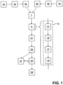
- FIG. 1 the schematic sequence of the method according to the invention for producing a polymer-refined pipeline element according to a preferred embodiment is shown.
- steps 1a, 1b a first hollow body and a second hollow body are provided.
- steps 3a, b edge surfaces are provided on the hollow bodies, preferably by means of plasma cutting.
- the hollow bodies receive edge surfaces either on one or both of their end faces or on a wall section spaced apart from the respective end faces, the latter in the form of a cutout.
- the first and second hollow bodies are cleaned on the edge surfaces, preferably using a rotary brush. If plasma cutting was used in the previous step to create the edge surfaces, metal oxides and loose particles as well as burrs created by brushing are removed as far as possible.
- first hollow body and the second hollow body are aligned with each other in such a way that an edge surface of one hollow body is aligned and arranged as close as possible to a corresponding edge surface of the other hollow body.
- the hollow bodies can be aligned with each other manually or using single- or multi-joint robots.
- a next process step 9 the previously aligned hollow bodies are welded together along the aligned peripheral edge surfaces, so that a completely circumferential weld seam is produced, which has a root extending on the inside of the pipeline element.
- a single-layer weld seam is applied.
- the welded hollow bodies are prepared for subsequent coating in a process step 21, which in turn can have several sub-steps not shown in detail.
- the preparation includes cleaning the welded hollow bodies in one or more immersion baths in which, for example, pickling agents or rinsing media such as demineralized water can be kept. The exact number and arrangement of the preparation steps depends on the specifications of the coating material to be used.
- the welded hollow bodies prepared in step 21 are then welded in one or more immersions using a Chemically coated using the autodeposition process.
- the immersion process ensures that the entire inside, including the weld seam, but also the outside of the hollow body is essentially completely coated.
- a thermal post-treatment takes place in a step 25.
- the step 25 can comprise one or more sub-steps, in each of which a flash-off or a tempering with predetermined temperatures and tempering times takes place (low tempering or high tempering).
- the pipe elements coated and post-treated in this way, which were produced from the hollow bodies can be powder-coated in a step 27.
- the powder coating is also preferably cured in a thermal post-treatment in step 25.
- step 29 the piping element is removed from the manufacturing process and is ready for use.
- step 25 for thermal post-treatment of the piping elements is shown as a single step. However, several successive heat treatment stages can take place in step 25, which are carried out in one or more different facilities.
- the welding process according to step 9 can be optimized, for example, by measuring the diameters of the hollow bodies and the wall thicknesses of the hollow bodies, particularly in the area of the edge surfaces, in a measuring step 13, which can be carried out at any time between steps 1a, b and welding step 9.
- online measurement is carried out, for example optically using gap detection, directly during the edge surface generation process step, and the welding parameters are then adjusted on the basis of the measured values to compensate for any deviations found in the measured geometry from the initial geometry for which the original welding parameters were stored. This makes it possible to compensate for the effects of the deviations, for example any out-of-roundness of the hollow body, in the welding process itself.
- a set of parameters for the optimal application of the weld seam is preferably selected from a predefined value table in a method step 15.
- the parameters stored in the predefined value table for each diameter and each wall thickness preferably include the feed, the path of the welding tool, the choice of a welding filler and, in the case of Arc welding, the voltage to be used, the feed rate of the welding wire, etc.
- a subsequent step 17 the previously determined parameters are preferably read into the welding tool or, if welding is to be carried out manually, made available to the operator so that the welding of the first and second hollow bodies can take place in the subsequent step 19.
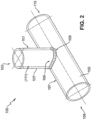
- a pipeline element 100 which has a first hollow body 101 and a second hollow body 102.
- the first hollow body 101 and the second hollow body 102 are connected by means of a single-layer, completely circumferential weld seam 109.
- the pipeline element 100 has a polymer-based layer 111 which extends completely along the inner sides of the hollow bodies 101, 102 and also completely covers the circumferential weld seam 109 on the inner side of the pipeline element 100. If the pipeline element was coated in a dipping process, the outer surface of the first and second hollow bodies 101, 102 and the weld seam 109 are also at least largely covered by the polymer-based layer.
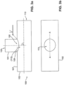
- the first hollow body 101 is arranged approximately centrally between a first end face 108 and a second end face 110 of the second hollow body 102 and, as can be seen in particular in Figures 3a, b can be seen, aligned as coaxially as possible with a cutout 113 formed in the side wall 107 of the second hollow body 102.
- the first hollow body 101 and the second hollow body 102 are aligned with each other at an angle ⁇ , which can be in a range of around 90°, for example.
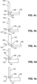
- Figure 4a It is initially shown that the edge surface 115 of the first hollow body 101 extends into the opening 113 defined by the edge surface of the second hollow body 102.
- the first hollow body 101 and the second hollow body 102 are aligned with one another and the cutout 113 in the second hollow body 102 is dimensioned such that the edge surface 115 of the first hollow body 101 is only connected to the second hollow body 102 at the outer peripheral edge, or extends completely within the cutout 113.
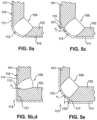
- a weld seam as in Figure 5a is shown.
- the term "ideal case” here means a correct selection of a predefined set of parameters that take into account the exact dimensions of the hollow bodies 101 and 102 and the position of the edge surfaces 115, 117.
- an alignment between the first hollow body 101 and the second hollow body 102 is essentially as in Figure 4a so that the edge surface 115 is provided with an external circumferential edge rests against the edge surface 117 of the second hollow body 102 or is adjacent to it there.
- Figure 4d differs in terms of the dimensions of the first hollow body relative to the second hollow body from Figure 4b .
- the same welding pattern is to be expected in terms of quality, which is why the above versions and Figures 5b,d is referred to.
- Figure 4e again shows an alignment of the first and second hollow bodies 101, 102 relative to each other, as is also the case with the Figures 4a and 4c were already selected.
- the material thickness of the second hollow body 102 is selected so that a welding pattern according to Figure 5e provided the correct parameter set is selected.
- the hollow bodies 101 and 102 are ideally completely covered by a root 112 of the weld seam 109 at edge surfaces 115, 117, so that a smooth transition is created between an inner side 118 of the first hollow body 101 and an inner side 119 of the second hollow body 102.
- the polymer-based layer 111 can ideally be applied to this geometry.
- the root 112 of the weld seam 109 also runs completely around the connection point between the first hollow body 101 and the second hollow body 102.
- FIG. 5c a variant is shown in which, due to the material thickness of the first hollow body 101, not the complete edge surface 115 of the first hollow body 101 of the root 112 of the weld seam 109 was detected, so that a part, namely in the region of an inner edge 121, protrudes radially inward from the weld seam 109, relative to the first hollow body 101.
- the threshold for the flow resistance created by the remaining edge surface 115 is within tolerable limits.
- complete wetting of the inside of the pipeline element with the polymer-based layer 111 is not significantly impaired by this.
- the value h 2 is preferably in a range of 0.5 times the difference in the wall thickness of the walls 107, if they have the same wall thickness, or less.
- h2 is preferably less than the difference between the two wall thicknesses of the hollow bodies 101, 102, if the wall thicknesses are different from one another.
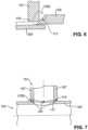
- the hollow bodies 101, 102 are preferably aligned according to Figure 6 selected.
- the edge surface 115 of the first hollow body 101 and/or the edge surface 117 of the second hollow body 102 is particularly preferably bevelled. This significantly reduces the amount of material to be melted. Since the material thickness in the area of the weld seam 109 to be produced can be very small, it is advantageous to introduce a bath support 200 into the second hollow body 102, which prevents the molten metal from sagging.
- Figure 5e is analogous to Figure 5c shown in which, due to the material thickness of one of the hollow bodies, in this case the second hollow body 10, both edge surfaces of the first hollow body 101 and the second hollow body 102 are not completely covered. In this case, it is an inner edge 123 on the cutout 113 in the second hollow body 102, which is spaced by a predetermined value h 3 from the root 112 of the weld seam 109, so that part of the edge surface 117 of the second hollow body 102 is still visible.
- h 3 does not exceed a predetermined maximum value, preferably determined as h 2 above, the complete formation of a polymer-based layer 111 is not hindered, and the flow conditions are not unduly impaired.
- the advantages of the embodiments according to the Figures 5c and e are technically much easier to control.
- the diameter and material thickness tolerances of the first hollow body 101 and the second hollow body 102 can be reduced compared to the embodiments of the Figures 5a and 5b,d be more generously dimensioned, which simplifies the pre-selection of suitable parameter sets.
- the first hollow body 101 preferably has a number of projections 125 on its edge surface 115, which can be designed as pins, for example, and which specify a predefined gap distance to the second hollow body 102 when the two hollow bodies 101, 102 are as in Figure 7 shown are aligned with each other.
- the projections ensure that the gap distance between the hollow bodies 101, 102 remains constant during welding and facilitate the creation of a weld seam 109 with complete root coverage of at least the edge surface 115 of the first hollow body 101, or even the edge surfaces 115, 117 of both hollow bodies 101, 102.
- the aspect of local flattening is shown using the example of the second hollow body 102.
- the second hollow body 102 has been pressed in over an area B by a depth T, for example by means of a pressing tool.
- the wall 107 of the second hollow body 102 is essentially flat. This makes it possible to form the edge surface 115 of the first hollow body 101 as a flat end face, which is advantageous in terms of production economy.
- the weld seam 109 therefore also extends essentially flat in the flattened area B along the circumference of the edge surface 115.
- the depth T is preferably a function of the material thickness of the wall 107 of the second hollow body and the nominal width of the first hollow body 101. In preferred embodiments, the depth T is in a range from 0.05 times to 0.18 times the nominal width of the flattened hollow body, in Figure 8 i.e. the hollow body 102.
- first hollow body 101 represents a connection element and the second hollow body 102 is a base pipe.
- second hollow body 102 is a base pipe.
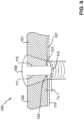
- a pipeline element 100 with a circumferential weld seam 109 is now shown, in which both the first hollow body 101 and the second hollow body 102 are each a base pipe.
- the hollow bodies 101 and 102 are arranged coaxially to one another and axially adjacent to one another.
- the hollow bodies 101 and 102 each have an edge surface 115, 117 facing the other hollow body.
- a root 112 of the weld seam 109 extends circumferentially completely in a circle within the pipeline element 100.
- the edge surfaces 115, 117 are each still delimited by a circumferential inner edge 121, 123.
- the circumferential inner edges 121, 123 are in the welded state, it is completely covered by the root 112 of the weld seam 109.
- the root 112 of the weld seam now forms a comparatively gentle transition.
- the root 112 of the weld seam 109 protrudes by a predetermined maximum value h 1 radially inside the wall 107 of the pipeline element 100.
- the amount by which the root 112 protrudes inwards is preferably 0.7 times the material thickness of the wall 107 of the hollow bodies or less.
- the welding parameters required for the predetermined pipe diameter are determined to produce the root 112 at the desired height h 1 , see above.
- the appropriate parameter set is selected from the predefined list and the welding process is carried out using this. The procedure is basically the same, regardless of whether the welding is automated, partially automated or manual.
- the pipe element 100 has according to Figure 9 also has a polymer-based layer 111 which extends completely along the inner sides of the hollow bodies 101, 102 and also completely covers the circumferential weld seam 109 on the inside of the pipe 100. If the pipeline element was coated in a dipping process, the outer surface of the first and second hollow bodies 101, 102 and the weld seam 109 are also at least largely covered by the polymer-based layer 111.
- the invention has succeeded for the first time in expanding the application area of polymer finishing to include complex pipeline elements with one or more welded joints.
- the invention proposes an advantageous further development.
Landscapes
- Engineering & Computer Science (AREA)
- General Engineering & Computer Science (AREA)
- Mechanical Engineering (AREA)
- Health & Medical Sciences (AREA)
- Public Health (AREA)
- Business, Economics & Management (AREA)
- Emergency Management (AREA)
- Life Sciences & Earth Sciences (AREA)
- Wood Science & Technology (AREA)
- Rigid Pipes And Flexible Pipes (AREA)
Claims (14)
- Procédé de fabrication d'un élément de conduite tubulaire (100) revêtu de polymère, en particulier d'un élément de conduite tubulaire (100) d'un système extincteur, dans lequel le procédé comprend les étapes :- de fourniture d'un premier corps creux (101) et d'un deuxième corps creux (102), dans lequel le premier et le deuxième corps creux (101, 102) présentent respectivement une paroi (107) et la paroi (107) présente respectivement une surface d'arête périphérique (115, 117), dans lequel la surface d'arête périphérique (115) du premier corps creux (101) est réalisée sur une extrémité frontale (105) du corps creux (101), et dans lequel la surface d'arête périphérique (117) du deuxième corps creux (102) est tenue à distance par rapport aux extrémités frontales (108, 110) du deuxième corps creux (101) et définit une découpe (113) à travers la paroi du deuxième corps creux (102),- d'orientation de la surface d'arête périphérique (115) du premier corps creux (101) et de la surface d'arête périphérique (117) du deuxième corps creux (102) l'une sur l'autre,- de soudage du premier corps creux (101) au deuxième corps creux (102) le long des surfaces d'arête périphériques (115, 117), dans lequel un joint de soudure (109) totalement périphérique est produit, lequel présente une racine (112) s'étendant sur le côté intérieur de l'élément de conduite tubulaire (100), ainsi que- d'application d'une couche à base de polymère (111) sur le côté intérieur de l'élément de conduite tubulaire (100), dans lequel la couche à base de polymère (111) recouvre totalement le côté intérieur de l'élément de conduite tubulaire et la racine du joint de soudure (109).
- Procédé selon la revendication 1,dans lequel les surfaces d'arête (115, 117) du premier et du deuxième corps creux (101, 102) présentent respectivement une arête intérieure périphérique (121, 123), et l'étape du soudage comprend :- la réalisation de la racine (112) du joint de soudure (109) dans une épaisseur qui renferme totalement au moins une des arêtes intérieures (115 ; 117) et de préférence les deux arêtes intérieures (115, 117), dans lequel de préférence la racine (112) du joint de soudure (109) renferme totalement l'arête intérieure périphérique (121, 123) d'un des corps creux (101, 102), et l'arête intérieure restante de l'autre corps creux est tenue à distance du joint de soudure (109) dans une direction radiale d'une valeur maximale prédéfinie (h2, h3),dans lequel par ailleurs de préférence la valeur maximale (h2, h3) prédéfiniea) dans la mesure où le premier et le deuxième corps creux présentent la même épaisseur de paroi, est inférieure ou égale à la moitié d'une épaisseur de paroi des corps creux, de manière particulièrement préférée est inférieure ou égale à un quart de l'épaisseur de paroi des corps creux, oub) dans la mesure où le premier et le deuxième corps creux présentent différentes épaisseurs de paroi, est inférieure ou égale à une différence des épaisseurs de paroi des corps creux, de manière particulièrement préférée est inférieure ou égale à la moitié de la différence des épaisseurs de paroi des corps creux.
- Procédé selon la revendication 2,
dans lequel l'étape du soudage comprend :
la réalisation de la racine (112) du joint de soudure (109) dans une épaisseur qui renferme totalement les arêtes intérieures (121, 123) des deux corps creux, dans lequel la racine (112) du joint de soudure (109) fait saillie radialement vers l'intérieur d'une valeur maximale prédéfinie d'un côté intérieur de la paroi du premier et/ou du deuxième corps creux, dans lequel la valeur maximale est de préférence inférieure ou égale à 0,7 fois l'épaisseur de paroi des corps creux. - Procédé selon l'une quelconque des revendications précédentes, comprenant en outre l'étape :
de production d'au moins une des surfaces d'arête périphériques (115, 117) du premier et/ou du deuxième corps creux (102) par coupage, de préférence par coupage au plasma. - Procédé selon l'une quelconque des revendications précédentes, comprenant en outre l'étape :
de nettoyage de la surface d'arête périphérique (115) ou des surfaces d'arête périphériques (115, 117) avant le soudage, de préférence après le coupage, en particulier le coupage au plasma. - Procédé selon la revendication 5,
dans lequel l'étape du nettoyage comprend l'élimination d'oxydes métalliques et de particules lâches de l'au moins une surface d'arête périphérique (115, 117), de préférence par brossage. - Procédé selon l'une quelconque des revendications 3 à 6, comprenant en outre l'étape :
d'aplatissement de la paroi du premier et/ou du deuxième corps creux (102) dans la zone dans laquelle précisément respectivement la surface d'arête périphérique (115, 117) s'étend ou doit être produite, de préférence avant l'étape du soudage et par ailleurs de préférence avant l'étape du coupage. - Procédé selon l'une quelconque des revendications précédentes,
dans lequel l'application de la couche à base de polymère est effectuée par immersion de l'élément de conduite tubulaire dans un bain d'immersion qui contient un matériau de revêtement correspondant. - Procédé selon l'une quelconque des revendications précédentes,
dans lequel les corps creux sont réalisés à partir d'un métal adapté pour le dépôt automatique par voie chimique, en particulier un métal contenant du fer et/ou contenant du zinc, et l'étape de l'application de la couche de polymère sur le côté intérieur de l'élément de conduite tubulaire (100) comprend :le revêtement, en particulier par dépôt automatique par voie chimique, de préférence par immersion de l'élément de conduite tubulaire (100) dans un bain d'immersion qui contient un matériau de dépôt automatique par voie chimique à base de polymère,dans lequel de préférence le matériau de dépôt automatique contient des constituants, lesquels seront liés de manière ionique à la paroi des corps creux et à la racine (112) du joint de soudure (109), et de préférence est présent en tant qu'émulsion ou dispersion aqueuse. - Procédé selon la revendication 9, dans lequel le matériau de dépôt automatique est de préférence acide, de préférence présente une valeur de pH dans une plage de 1 à 5, et comprend de préférence un matériau initiateur sous forme d'halogénures métalliques ; et/oudans lequel le matériau de dépôt automatique présente, en tant que constituant polymère, un ou plusieurs polymères pouvant être déposés de manière automatique, de préférence choisis parmi la liste constituée :i) d'époxydes,ii) d'acrylates,iii) de styroacrylates,iv) d'époxyacrylates,v) d'isocyanates, en particulier d'uréthanes, comme des polyuréthanes,vi) de polymères avec un groupe vinyle, par exemple du polychlorure de vinylidène, ouvii) une combinaison de deux ou de plus parmi i), ii) ou iii), qui sont liés transversalement de préférence les uns aux autres, par ailleurs de préférence par l'intermédiaire d'un isocyanate, de manière particulièrement préférée par l'intermédiaire d'un uréthane.
- Procédé selon la revendication 9 ou 10,
dans lequel l'étape de l'immersion, lors d'une ou plusieurs passes d'immersion, se poursuit jusqu'à ce que la couche à base de polymère appliquée sur le côté intérieur de l'élément de conduite tubulaire présente une épaisseur dans une plage de 7 µm à 80 µm, de préférence une épaisseur dans une plage de 7 µm à 30 µm. - Elément de conduite tubulaire (100), en particulier fabriqué dans un procédé selon l'une quelconque des revendications précédentes, avec :- un premier corps creux (101),- un deuxième corps creux (102),dans lequel les corps creux (101, 102) sont orientés l'un sur l'autre, et le premier et le deuxième corps creux (101, 102) sont reliés au moyen d'un joint de soudure (109) périphérique, dans lequel le joint de soudure (109) est réalisé sur une extrémité frontale (105) du premier corps creux (101), dans lequel le joint de soudure (109) est tenu à distance des extrémités frontales (108, 110) du deuxième corps creux (102), etdans lequel le joint de soudure (109) présente une racine (112) s'étendant sur le côté intérieur de l'élément de conduite tubulaire (100), et- une couche à base de polymère (111) sur le côté intérieur de l'élément de conduite tubulaire, dans lequel la couche à base de polymère (111) recouvre totalement le côté intérieur de l'élément de conduite tubulaire (100) et le joint de soudure (109).
- Système de conduite tubulaire d'un système extincteur, avecun nombre d'éléments de conduite tubulaire (100), qui sont couplés les uns aux autres,dans lequel un, plusieurs ou la totalité des éléments de conduite tubulaire sont réalisés selon la revendication 12.
- Utilisation d'un élément de conduite tubulaire dans un système de conduites tubulaires d'un système extincteur, dans laquelle un nombre d'éléments de conduite tubulaire sont couplés les uns aux autres, et dans laquelle un, plusieurs ou la totalité des éléments de conduites tubulaires sont réalisés selon la revendication 12.
Applications Claiming Priority (2)
| Application Number | Priority Date | Filing Date | Title |
|---|---|---|---|
| DE102018115525.5A DE102018115525A1 (de) | 2018-06-27 | 2018-06-27 | Verfahren zum Herstellen eines polymerveredelten Rohrleitungselements, sowie Rohrleitungselement und Rohrleitungssystem mit selbigem |
| PCT/EP2019/067154 WO2020002502A1 (fr) | 2018-06-27 | 2019-06-27 | Procédé pour la fabrication d'un élément de conduite tubulaire revêtu de polymère, ainsi qu'élément de conduite tubulaire et système de conduite tubulaire le comprenant |
Publications (2)
| Publication Number | Publication Date |
|---|---|
| EP3813962A1 EP3813962A1 (fr) | 2021-05-05 |
| EP3813962B1 true EP3813962B1 (fr) | 2024-12-04 |
Family
ID=67297121
Family Applications (1)
| Application Number | Title | Priority Date | Filing Date |
|---|---|---|---|
| EP19739915.7A Active EP3813962B1 (fr) | 2018-06-27 | 2019-06-27 | Procédé pour la fabrication d'un élément de conduite tubulaire revêtu de polymère, ainsi qu'élément de conduite tubulaire et système de conduite tubulaire le comprenant |
Country Status (5)
| Country | Link |
|---|---|
| US (1) | US12066143B2 (fr) |
| EP (1) | EP3813962B1 (fr) |
| CN (1) | CN216986161U (fr) |
| DE (1) | DE102018115525A1 (fr) |
| WO (1) | WO2020002502A1 (fr) |
Families Citing this family (4)
| Publication number | Priority date | Publication date | Assignee | Title |
|---|---|---|---|---|
| DE102018115533A1 (de) | 2018-06-27 | 2020-01-02 | Minimax Viking Research & Development Gmbh | Verfahren zur Herstellung einer Anzahl von Rohren mit einem vorbestimmten Rohrdurchmesser, Rohr, sowie Rohrleitungssystem |
| DE102018115506A1 (de) | 2018-06-27 | 2020-01-02 | Minimax Viking Research & Development Gmbh | Verfahren zum Herstellen eines Rohrleitungselements, insbesondere eines Rohrleitungselements einer Feuerlöschanlage, Rohrleitungselement und Rohrleitungssystem im selbigen |
| EP4267336A1 (fr) * | 2020-12-23 | 2023-11-01 | Minimax Viking Research & Development GmbH | Procédé de production d'un élément tubulaire amélioré au polymère |
| PL445069A1 (pl) * | 2023-05-31 | 2024-12-02 | Tasta Armatura Spółka Z Ograniczoną Odpowiedzialnością | Prefabrykowane rurociągi do tryskaczowych instalacji przeciwpożarowych z zastosowaniem spawania pełnoprzetopowymi spoinami czołowymi |
Citations (1)
| Publication number | Priority date | Publication date | Assignee | Title |
|---|---|---|---|---|
| EP0344896A1 (fr) * | 1988-06-03 | 1989-12-06 | Norio Takei | Laminé pour le gainage de conduites et méthode d'application |
Family Cites Families (19)
| Publication number | Priority date | Publication date | Assignee | Title |
|---|---|---|---|---|
| US1966403A (en) | 1931-03-05 | 1934-07-10 | Nassau Products | Welding union |
| US2915324A (en) | 1956-11-30 | 1959-12-01 | Bonney Forge & Tool Works | Welded outlet fitting |
| FR2311980A1 (fr) | 1975-05-21 | 1976-12-17 | Heimberger Roland | Dispositif de tracage et de decoupage, utilisable notamment pour des coupes de tuyaux |
| DE3011256C2 (de) | 1980-03-24 | 1982-07-01 | J. & W. Müller, Maschinen- und Armaturen-Fabrik, GmbH, 5090 Leverkusen | Vorrichtung zum Schneiden der Wandung eines Rohres in einer geschlossenen Schnittfläche |
| DD269807A1 (de) * | 1988-03-10 | 1989-07-12 | Zentralinstitut Schweiss | Selbstjustierender schweisskopf fuer das schutzgasschweissen |
| US5030812A (en) * | 1989-06-13 | 1991-07-09 | Nkk Corporation | Method for one-side root pass welding of a pipe joint |
| DE50208575D1 (de) | 2001-06-15 | 2006-12-14 | Josch Strahlschweistechnik Gmb | Grundkörper aus gefügten Rohrstücken und Verfahren zu seiner Herstellung |
| WO2003001103A1 (fr) | 2001-06-21 | 2003-01-03 | Maxtech Manufacturing Inc. | Bossages et procede d'attache correspondant |
| US8709535B2 (en) * | 2005-09-30 | 2014-04-29 | Harley-Davidson Motor Company Group, Inc. | Method of enhancing corrosion resistance of hollow vessels |
| DE102010027182A1 (de) * | 2010-07-14 | 2012-01-19 | Thyssenkrupp Tailored Blanks Gmbh | Rohrförmiges Bauteil aus miteinander im Stumpfstoß verschweißten Metallrohren unterschiedlicher Wandstärke und Verfahren zu dessen Herstellung |
| HUE030770T2 (en) * | 2012-02-05 | 2017-05-29 | Minimax Gmbh & Co Kg | Tûzoltórendszer |
| US10400135B2 (en) * | 2012-11-26 | 2019-09-03 | Chemetall Gmbh | Method for coating metal surfaces of substrates, and objects coated according to said method |
| US11767934B2 (en) * | 2013-05-23 | 2023-09-26 | Crc-Evans Pipeline International, Inc. | Internally welded pipes |
| DE102014102621A1 (de) * | 2014-02-27 | 2015-08-27 | Doege Beteiligungs Gmbh | Grossrohranordnung und Verfahren zur Herstellung einer solchen |
| KR20190042233A (ko) | 2017-10-16 | 2019-04-24 | (주) 신테크 | 티형 배관 용접장치 |
| DE102018115506A1 (de) | 2018-06-27 | 2020-01-02 | Minimax Viking Research & Development Gmbh | Verfahren zum Herstellen eines Rohrleitungselements, insbesondere eines Rohrleitungselements einer Feuerlöschanlage, Rohrleitungselement und Rohrleitungssystem im selbigen |
| DE102018115537A1 (de) | 2018-06-27 | 2020-01-02 | Minimax Viking Research & Development Gmbh | Tragevorrichtung zur Aufnahme eines Rohrleitungselements, betreffendes Transportsystem sowie Herstellungsverfahren |
| DE102018115533A1 (de) | 2018-06-27 | 2020-01-02 | Minimax Viking Research & Development Gmbh | Verfahren zur Herstellung einer Anzahl von Rohren mit einem vorbestimmten Rohrdurchmesser, Rohr, sowie Rohrleitungssystem |
| EP4267336A1 (fr) | 2020-12-23 | 2023-11-01 | Minimax Viking Research & Development GmbH | Procédé de production d'un élément tubulaire amélioré au polymère |
-
2018
- 2018-06-27 DE DE102018115525.5A patent/DE102018115525A1/de not_active Withdrawn
-
2019
- 2019-06-27 CN CN201990000822.6U patent/CN216986161U/zh active Active
- 2019-06-27 WO PCT/EP2019/067154 patent/WO2020002502A1/fr not_active Ceased
- 2019-06-27 EP EP19739915.7A patent/EP3813962B1/fr active Active
- 2019-06-27 US US17/252,211 patent/US12066143B2/en active Active
Patent Citations (1)
| Publication number | Priority date | Publication date | Assignee | Title |
|---|---|---|---|---|
| EP0344896A1 (fr) * | 1988-06-03 | 1989-12-06 | Norio Takei | Laminé pour le gainage de conduites et méthode d'application |
Also Published As
| Publication number | Publication date |
|---|---|
| EP3813962A1 (fr) | 2021-05-05 |
| WO2020002502A1 (fr) | 2020-01-02 |
| US12066143B2 (en) | 2024-08-20 |
| CN216986161U (zh) | 2022-07-19 |
| DE102018115525A1 (de) | 2020-01-02 |
| US20210254777A1 (en) | 2021-08-19 |
Similar Documents
| Publication | Publication Date | Title |
|---|---|---|
| EP3813961B1 (fr) | Procédé pour la fabrication d'un élément de conduite tubulaire, en particulier d'un élément de conduite tubulaire d'une installation d'extinction de feu, élément de conduite tubulaire et système de conduite tubulaire dans celui-ci | |
| DE2100442C3 (de) | Verfahren und Sprühdüse zur Beschichtung der Innenflächen von einseitig geschlossenen zylindrischen Hohlkörpern | |
| WO2020002502A1 (fr) | Procédé pour la fabrication d'un élément de conduite tubulaire revêtu de polymère, ainsi qu'élément de conduite tubulaire et système de conduite tubulaire le comprenant | |
| DE19700583C2 (de) | Verbindungsanordnung zum Verbinden von Ösenmuffen und dünnen Metallrohren und Verfahren zu deren Herstellung | |
| WO2015036189A1 (fr) | Tuyau de mesure conçu pour un débitmètre à ultrason et débitmètre à ultrason | |
| EP2373920A1 (fr) | Réservoir à air comprimé pour véhicules utilitaires et procédé de fabrication de celui-ci | |
| EP3814664B1 (fr) | Procédé pour la fabrication d'un certain nombre de tubes présentant un diamètre prédéfini, tube, ainsi que système de conduite | |
| EP4267336A1 (fr) | Procédé de production d'un élément tubulaire amélioré au polymère | |
| EP1622737A2 (fr) | Buse de gaz pour une torche de soudage, torche de soudage ayant une couche de patine; dispositif de nettoyage pour une torche de soudage avec des poils en materiau elastique souple et contenant des grains abrasifs | |
| WO2020038929A1 (fr) | Procédé pour produire un corps à enveloppe tubulaire légère et corps à enveloppe tubulaire légère | |
| DE102019213464B4 (de) | Verfahren zum Herstellen eines Reibbremskörpers für eine Reibbremse eines Kraftfahrzeugs | |
| WO2014187688A1 (fr) | Procédé de fabrication d'un élément structural concave ainsi qu'équipement de production pour la mise en oeuvre de ce procédé | |
| DE102009005098A1 (de) | Rohrverbindungskonstruktion für ein Endoskop und Verfahren zu deren Herstellung | |
| EP3935301B1 (fr) | Tuyau métallique pour le transport de pétrole et de gaz, comprenant un revêtement métallique dans une zone de transition | |
| DE69901625T2 (de) | Verfahren zum verbinden von zwei koaxialen rohren, werkzeug zur herstellung der verbindung und anwendung des verfahrens | |
| DE102009012973A1 (de) | Anschlussverbindung für zylindrische Elemente und Verfahren zum Herstellen einer solchen | |
| DE19854284C1 (de) | Verfahren zur Herstellung von Rohrprofilelementen mit angestauchtem Kopfende sowie als Schalldämpferaufhängung ausgebildetes Rohrprofilelement hergestellt nach diesem Verfahren | |
| DE102013223931A1 (de) | Flanschelement, Verfahren zum Verbinden eines ersten Rohres mit einem zweiten Rohr | |
| DE102006058218A1 (de) | Verfahren und vorbearbeitetes Rohr zum Herstellen eines Rohrs mit abknickendem Verlauf oder mit als Polygonzug ausgeführter Biegung | |
| EP3911490A1 (fr) | Procédé et dispositif pour fabriquer une conduite de fluide pourvue d'un élément de liaison | |
| DE4328515A1 (de) | Verfahren und Vorrichtung zur Herstellung einer Schweißkonstruktion | |
| DE102021113474B3 (de) | Verfahren zum Verschließen von Rohrenden | |
| EP3705766B1 (fr) | Méthode de raccordement d'extrémités de tuyaux en acier | |
| DE19801656A1 (de) | Heizkörper mit Verbindungsabschnitten, die einen ellipsenförmigen Querschnitt aufweisen, und Verfahren zu dessen Herstellung | |
| DE4443839C1 (de) | Verfahren zum Herstellen einer aktiv gekühlten Triebwerkswand |
Legal Events
| Date | Code | Title | Description |
|---|---|---|---|
| STAA | Information on the status of an ep patent application or granted ep patent |
Free format text: STATUS: UNKNOWN |
|
| STAA | Information on the status of an ep patent application or granted ep patent |
Free format text: STATUS: THE INTERNATIONAL PUBLICATION HAS BEEN MADE |
|
| PUAI | Public reference made under article 153(3) epc to a published international application that has entered the european phase |
Free format text: ORIGINAL CODE: 0009012 |
|
| STAA | Information on the status of an ep patent application or granted ep patent |
Free format text: STATUS: REQUEST FOR EXAMINATION WAS MADE |
|
| 17P | Request for examination filed |
Effective date: 20210127 |
|
| AK | Designated contracting states |
Kind code of ref document: A1 Designated state(s): AL AT BE BG CH CY CZ DE DK EE ES FI FR GB GR HR HU IE IS IT LI LT LU LV MC MK MT NL NO PL PT RO RS SE SI SK SM TR |
|
| DAV | Request for validation of the european patent (deleted) | ||
| DAX | Request for extension of the european patent (deleted) | ||
| STAA | Information on the status of an ep patent application or granted ep patent |
Free format text: STATUS: EXAMINATION IS IN PROGRESS |
|
| 17Q | First examination report despatched |
Effective date: 20221219 |
|
| P01 | Opt-out of the competence of the unified patent court (upc) registered |
Effective date: 20230602 |
|
| GRAP | Despatch of communication of intention to grant a patent |
Free format text: ORIGINAL CODE: EPIDOSNIGR1 |
|
| STAA | Information on the status of an ep patent application or granted ep patent |
Free format text: STATUS: GRANT OF PATENT IS INTENDED |
|
| INTG | Intention to grant announced |
Effective date: 20240710 |
|
| GRAS | Grant fee paid |
Free format text: ORIGINAL CODE: EPIDOSNIGR3 |
|
| RAP1 | Party data changed (applicant data changed or rights of an application transferred) |
Owner name: MINIMAX VIKING PATENT MANAGEMENT GMBH |
|
| GRAA | (expected) grant |
Free format text: ORIGINAL CODE: 0009210 |
|
| STAA | Information on the status of an ep patent application or granted ep patent |
Free format text: STATUS: THE PATENT HAS BEEN GRANTED |
|
| AK | Designated contracting states |
Kind code of ref document: B1 Designated state(s): AL AT BE BG CH CY CZ DE DK EE ES FI FR GB GR HR HU IE IS IT LI LT LU LV MC MK MT NL NO PL PT RO RS SE SI SK SM TR |
|
| REG | Reference to a national code |
Ref country code: GB Ref legal event code: FG4D Free format text: NOT ENGLISH |
|
| REG | Reference to a national code |
Ref country code: CH Ref legal event code: EP |
|
| REG | Reference to a national code |
Ref country code: DE Ref legal event code: R096 Ref document number: 502019012599 Country of ref document: DE |
|
| REG | Reference to a national code |
Ref country code: IE Ref legal event code: FG4D Free format text: LANGUAGE OF EP DOCUMENT: GERMAN |
|
| REG | Reference to a national code |
Ref country code: LT Ref legal event code: MG9D |
|
| REG | Reference to a national code |
Ref country code: NL Ref legal event code: MP Effective date: 20241204 |
|
| PG25 | Lapsed in a contracting state [announced via postgrant information from national office to epo] |
Ref country code: HR Free format text: LAPSE BECAUSE OF FAILURE TO SUBMIT A TRANSLATION OF THE DESCRIPTION OR TO PAY THE FEE WITHIN THE PRESCRIBED TIME-LIMIT Effective date: 20241204 |
|
| PG25 | Lapsed in a contracting state [announced via postgrant information from national office to epo] |
Ref country code: FI Free format text: LAPSE BECAUSE OF FAILURE TO SUBMIT A TRANSLATION OF THE DESCRIPTION OR TO PAY THE FEE WITHIN THE PRESCRIBED TIME-LIMIT Effective date: 20241204 |
|
| PG25 | Lapsed in a contracting state [announced via postgrant information from national office to epo] |
Ref country code: BG Free format text: LAPSE BECAUSE OF FAILURE TO SUBMIT A TRANSLATION OF THE DESCRIPTION OR TO PAY THE FEE WITHIN THE PRESCRIBED TIME-LIMIT Effective date: 20241204 |
|
| PG25 | Lapsed in a contracting state [announced via postgrant information from national office to epo] |
Ref country code: ES Free format text: LAPSE BECAUSE OF FAILURE TO SUBMIT A TRANSLATION OF THE DESCRIPTION OR TO PAY THE FEE WITHIN THE PRESCRIBED TIME-LIMIT Effective date: 20241204 |
|
| PG25 | Lapsed in a contracting state [announced via postgrant information from national office to epo] |
Ref country code: NO Free format text: LAPSE BECAUSE OF FAILURE TO SUBMIT A TRANSLATION OF THE DESCRIPTION OR TO PAY THE FEE WITHIN THE PRESCRIBED TIME-LIMIT Effective date: 20250304 |
|
| PG25 | Lapsed in a contracting state [announced via postgrant information from national office to epo] |
Ref country code: LV Free format text: LAPSE BECAUSE OF FAILURE TO SUBMIT A TRANSLATION OF THE DESCRIPTION OR TO PAY THE FEE WITHIN THE PRESCRIBED TIME-LIMIT Effective date: 20241204 Ref country code: GR Free format text: LAPSE BECAUSE OF FAILURE TO SUBMIT A TRANSLATION OF THE DESCRIPTION OR TO PAY THE FEE WITHIN THE PRESCRIBED TIME-LIMIT Effective date: 20250305 |
|
| PG25 | Lapsed in a contracting state [announced via postgrant information from national office to epo] |
Ref country code: RS Free format text: LAPSE BECAUSE OF FAILURE TO SUBMIT A TRANSLATION OF THE DESCRIPTION OR TO PAY THE FEE WITHIN THE PRESCRIBED TIME-LIMIT Effective date: 20250304 |
|
| PG25 | Lapsed in a contracting state [announced via postgrant information from national office to epo] |
Ref country code: NL Free format text: LAPSE BECAUSE OF FAILURE TO SUBMIT A TRANSLATION OF THE DESCRIPTION OR TO PAY THE FEE WITHIN THE PRESCRIBED TIME-LIMIT Effective date: 20241204 |
|
| PG25 | Lapsed in a contracting state [announced via postgrant information from national office to epo] |
Ref country code: SM Free format text: LAPSE BECAUSE OF FAILURE TO SUBMIT A TRANSLATION OF THE DESCRIPTION OR TO PAY THE FEE WITHIN THE PRESCRIBED TIME-LIMIT Effective date: 20241204 |
|
| PG25 | Lapsed in a contracting state [announced via postgrant information from national office to epo] |
Ref country code: PL Free format text: LAPSE BECAUSE OF FAILURE TO SUBMIT A TRANSLATION OF THE DESCRIPTION OR TO PAY THE FEE WITHIN THE PRESCRIBED TIME-LIMIT Effective date: 20241204 |
|
| PGFP | Annual fee paid to national office [announced via postgrant information from national office to epo] |
Ref country code: GB Payment date: 20250620 Year of fee payment: 7 |
|
| PG25 | Lapsed in a contracting state [announced via postgrant information from national office to epo] |
Ref country code: IS Free format text: LAPSE BECAUSE OF FAILURE TO SUBMIT A TRANSLATION OF THE DESCRIPTION OR TO PAY THE FEE WITHIN THE PRESCRIBED TIME-LIMIT Effective date: 20250404 |
|
| PG25 | Lapsed in a contracting state [announced via postgrant information from national office to epo] |
Ref country code: PT Free format text: LAPSE BECAUSE OF FAILURE TO SUBMIT A TRANSLATION OF THE DESCRIPTION OR TO PAY THE FEE WITHIN THE PRESCRIBED TIME-LIMIT Effective date: 20250404 |
|
| PG25 | Lapsed in a contracting state [announced via postgrant information from national office to epo] |
Ref country code: EE Free format text: LAPSE BECAUSE OF FAILURE TO SUBMIT A TRANSLATION OF THE DESCRIPTION OR TO PAY THE FEE WITHIN THE PRESCRIBED TIME-LIMIT Effective date: 20241204 |
|
| PGFP | Annual fee paid to national office [announced via postgrant information from national office to epo] |
Ref country code: FR Payment date: 20250626 Year of fee payment: 7 |
|
| PG25 | Lapsed in a contracting state [announced via postgrant information from national office to epo] |
Ref country code: RO Free format text: LAPSE BECAUSE OF FAILURE TO SUBMIT A TRANSLATION OF THE DESCRIPTION OR TO PAY THE FEE WITHIN THE PRESCRIBED TIME-LIMIT Effective date: 20241204 |
|
| PG25 | Lapsed in a contracting state [announced via postgrant information from national office to epo] |
Ref country code: SK Free format text: LAPSE BECAUSE OF FAILURE TO SUBMIT A TRANSLATION OF THE DESCRIPTION OR TO PAY THE FEE WITHIN THE PRESCRIBED TIME-LIMIT Effective date: 20241204 |
|
| PG25 | Lapsed in a contracting state [announced via postgrant information from national office to epo] |
Ref country code: CZ Free format text: LAPSE BECAUSE OF FAILURE TO SUBMIT A TRANSLATION OF THE DESCRIPTION OR TO PAY THE FEE WITHIN THE PRESCRIBED TIME-LIMIT Effective date: 20241204 |
|
| PG25 | Lapsed in a contracting state [announced via postgrant information from national office to epo] |
Ref country code: IT Free format text: LAPSE BECAUSE OF FAILURE TO SUBMIT A TRANSLATION OF THE DESCRIPTION OR TO PAY THE FEE WITHIN THE PRESCRIBED TIME-LIMIT Effective date: 20241204 |
|
| REG | Reference to a national code |
Ref country code: DE Ref legal event code: R097 Ref document number: 502019012599 Country of ref document: DE |
|
| PG25 | Lapsed in a contracting state [announced via postgrant information from national office to epo] |
Ref country code: SE Free format text: LAPSE BECAUSE OF FAILURE TO SUBMIT A TRANSLATION OF THE DESCRIPTION OR TO PAY THE FEE WITHIN THE PRESCRIBED TIME-LIMIT Effective date: 20241204 |
|
| PG25 | Lapsed in a contracting state [announced via postgrant information from national office to epo] |
Ref country code: DK Free format text: LAPSE BECAUSE OF FAILURE TO SUBMIT A TRANSLATION OF THE DESCRIPTION OR TO PAY THE FEE WITHIN THE PRESCRIBED TIME-LIMIT Effective date: 20241204 |
|
| PGFP | Annual fee paid to national office [announced via postgrant information from national office to epo] |
Ref country code: DE Payment date: 20250701 Year of fee payment: 7 |
|
| PLBE | No opposition filed within time limit |
Free format text: ORIGINAL CODE: 0009261 |
|
| STAA | Information on the status of an ep patent application or granted ep patent |
Free format text: STATUS: NO OPPOSITION FILED WITHIN TIME LIMIT |
|
| REG | Reference to a national code |
Ref country code: CH Ref legal event code: L10 Free format text: ST27 STATUS EVENT CODE: U-0-0-L10-L00 (AS PROVIDED BY THE NATIONAL OFFICE) Effective date: 20251015 |
|
| 26N | No opposition filed |
Effective date: 20250905 |
|
| REG | Reference to a national code |
Ref country code: CH Ref legal event code: H13 Free format text: ST27 STATUS EVENT CODE: U-0-0-H10-H13 (AS PROVIDED BY THE NATIONAL OFFICE) Effective date: 20260127 |
|
| PG25 | Lapsed in a contracting state [announced via postgrant information from national office to epo] |
Ref country code: MC Free format text: LAPSE BECAUSE OF FAILURE TO SUBMIT A TRANSLATION OF THE DESCRIPTION OR TO PAY THE FEE WITHIN THE PRESCRIBED TIME-LIMIT Effective date: 20241204 |
|
| PG25 | Lapsed in a contracting state [announced via postgrant information from national office to epo] |
Ref country code: LU Free format text: LAPSE BECAUSE OF NON-PAYMENT OF DUE FEES Effective date: 20250627 |
|
| REG | Reference to a national code |
Ref country code: BE Ref legal event code: MM Effective date: 20250630 |
|
| PG25 | Lapsed in a contracting state [announced via postgrant information from national office to epo] |
Ref country code: IE Free format text: LAPSE BECAUSE OF NON-PAYMENT OF DUE FEES Effective date: 20250627 |
|
| PG25 | Lapsed in a contracting state [announced via postgrant information from national office to epo] |
Ref country code: BE Free format text: LAPSE BECAUSE OF NON-PAYMENT OF DUE FEES Effective date: 20250630 |
|
| PG25 | Lapsed in a contracting state [announced via postgrant information from national office to epo] |
Ref country code: CH Free format text: LAPSE BECAUSE OF NON-PAYMENT OF DUE FEES Effective date: 20250630 |