EP3814149B1 - Procédé et dispositif d'amélioration de produits imprimés - Google Patents
Procédé et dispositif d'amélioration de produits imprimés Download PDFInfo
- Publication number
- EP3814149B1 EP3814149B1 EP19732574.9A EP19732574A EP3814149B1 EP 3814149 B1 EP3814149 B1 EP 3814149B1 EP 19732574 A EP19732574 A EP 19732574A EP 3814149 B1 EP3814149 B1 EP 3814149B1
- Authority
- EP
- European Patent Office
- Prior art keywords
- substrate
- foil
- lacquer
- coated
- area
- Prior art date
- Legal status (The legal status is an assumption and is not a legal conclusion. Google has not performed a legal analysis and makes no representation as to the accuracy of the status listed.)
- Active
Links
Images


Classifications
-
- B—PERFORMING OPERATIONS; TRANSPORTING
- B44—DECORATIVE ARTS
- B44C—PRODUCING DECORATIVE EFFECTS; MOSAICS; TARSIA WORK; PAPERHANGING
- B44C1/00—Processes, not specifically provided for elsewhere, for producing decorative surface effects
- B44C1/16—Processes, not specifically provided for elsewhere, for producing decorative surface effects for applying transfer pictures or the like
- B44C1/165—Processes, not specifically provided for elsewhere, for producing decorative surface effects for applying transfer pictures or the like for decalcomanias; sheet material therefor
- B44C1/17—Dry transfer
- B44C1/1733—Decalcomanias applied under pressure only, e.g. provided with a pressure sensitive adhesive
-
- B—PERFORMING OPERATIONS; TRANSPORTING
- B32—LAYERED PRODUCTS
- B32B—LAYERED PRODUCTS, i.e. PRODUCTS BUILT-UP OF STRATA OF FLAT OR NON-FLAT, e.g. CELLULAR OR HONEYCOMB, FORM
- B32B15/00—Layered products comprising a layer of metal
- B32B15/04—Layered products comprising a layer of metal comprising metal as the main or only constituent of a layer, which is next to another layer of the same or of a different material
- B32B15/12—Layered products comprising a layer of metal comprising metal as the main or only constituent of a layer, which is next to another layer of the same or of a different material of paper or cardboard
-
- B—PERFORMING OPERATIONS; TRANSPORTING
- B41—PRINTING; LINING MACHINES; TYPEWRITERS; STAMPS
- B41J—TYPEWRITERS; SELECTIVE PRINTING MECHANISMS, i.e. MECHANISMS PRINTING OTHERWISE THAN FROM A FORME; CORRECTION OF TYPOGRAPHICAL ERRORS
- B41J11/00—Devices or arrangements of selective printing mechanisms, e.g. ink-jet printers or thermal printers, for supporting or handling copy material in sheet or web form
- B41J11/0015—Devices or arrangements of selective printing mechanisms, e.g. ink-jet printers or thermal printers, for supporting or handling copy material in sheet or web form for treating before, during or after printing or for uniform coating or laminating the copy material before or after printing
-
- B—PERFORMING OPERATIONS; TRANSPORTING
- B41—PRINTING; LINING MACHINES; TYPEWRITERS; STAMPS
- B41M—PRINTING, DUPLICATING, MARKING, OR COPYING PROCESSES; COLOUR PRINTING
- B41M5/00—Duplicating or marking methods; Sheet materials for use therein
- B41M5/50—Recording sheets characterised by the coating used to improve ink, dye or pigment receptivity, e.g. for ink-jet or thermal dye transfer recording
- B41M5/52—Macromolecular coatings
-
- B—PERFORMING OPERATIONS; TRANSPORTING
- B44—DECORATIVE ARTS
- B44C—PRODUCING DECORATIVE EFFECTS; MOSAICS; TARSIA WORK; PAPERHANGING
- B44C1/00—Processes, not specifically provided for elsewhere, for producing decorative surface effects
- B44C1/10—Applying flat materials, e.g. leaflets, pieces of fabrics
- B44C1/14—Metallic leaves or foils, e.g. gold leaf
-
- B—PERFORMING OPERATIONS; TRANSPORTING
- B44—DECORATIVE ARTS
- B44C—PRODUCING DECORATIVE EFFECTS; MOSAICS; TARSIA WORK; PAPERHANGING
- B44C1/00—Processes, not specifically provided for elsewhere, for producing decorative surface effects
- B44C1/10—Applying flat materials, e.g. leaflets, pieces of fabrics
- B44C1/14—Metallic leaves or foils, e.g. gold leaf
- B44C1/145—Devices for applying metal leaves of foils
-
- B—PERFORMING OPERATIONS; TRANSPORTING
- B44—DECORATIVE ARTS
- B44C—PRODUCING DECORATIVE EFFECTS; MOSAICS; TARSIA WORK; PAPERHANGING
- B44C1/00—Processes, not specifically provided for elsewhere, for producing decorative surface effects
- B44C1/16—Processes, not specifically provided for elsewhere, for producing decorative surface effects for applying transfer pictures or the like
- B44C1/165—Processes, not specifically provided for elsewhere, for producing decorative surface effects for applying transfer pictures or the like for decalcomanias; sheet material therefor
- B44C1/17—Dry transfer
- B44C1/1712—Decalcomanias applied under heat and pressure, e.g. provided with a heat activable adhesive
- B44C1/1729—Hot stamping techniques
-
- B—PERFORMING OPERATIONS; TRANSPORTING
- B44—DECORATIVE ARTS
- B44C—PRODUCING DECORATIVE EFFECTS; MOSAICS; TARSIA WORK; PAPERHANGING
- B44C1/00—Processes, not specifically provided for elsewhere, for producing decorative surface effects
- B44C1/16—Processes, not specifically provided for elsewhere, for producing decorative surface effects for applying transfer pictures or the like
- B44C1/165—Processes, not specifically provided for elsewhere, for producing decorative surface effects for applying transfer pictures or the like for decalcomanias; sheet material therefor
- B44C1/17—Dry transfer
- B44C1/1733—Decalcomanias applied under pressure only, e.g. provided with a pressure sensitive adhesive
- B44C1/1741—Decalcomanias provided with a layer being specially adapted to facilitate their release from a temporary carrier
Definitions
- the invention relates generally to the field of manufacturing printed products.
- the invention relates to the print finishing of printed products with foils.
- Print finishing is generally understood to mean the modification of the surface of printed products. Typically, such finishing is aesthetic in nature, in order to change the surface haptically and visually. The surface can also be protected against wear, fading or the absorption of dirt, for example, in order to improve the durability of the printed product.
- An example of such a process is sealing, in which the printed product is laminated with a plastic film over the entire surface and on both sides. Single-sided, full-surface lamination with plastic films is also widely used in the graphic industry.
- One method of print finishing is the local application of varnish to smooth coated areas or to give the surface a shine with the varnish layer.
- Screen printing and inkjet printing are among the methods used for this process.
- UV-curing varnishes are particularly suitable for the inkjet printing process, as they can be quickly cured after application and the risk of the varnish solidifying in the nozzles of the print head is avoided.
- Another process used in print finishing is the application of foils to the printed product.
- Special optical effects can be achieved with metallized foils, for example to produce gold or silver-colored lettering and decorations.
- An embossing effect is also often included here to further emphasize the metallized areas visually and haptically.
- a common process for this is hot foil stamping.
- a coating on the underside of the carrier film is bonded to the substrate using a heated metal stamp under pressure. At the same time, the metal stamp embosses the substrate.
- the carrier film is peeled off after embossing and only the coating remains on the substrate to be finished.
- At least one layer of the coating on the carrier film is a metal layer, usually created by vapor deposition with aluminum.
- the US 2010/0212821 A1 discloses a method for producing a relief with a film lamination.
- a curable adhesive is applied to the substrate and a film is pressed onto it so that it comes into contact with the adhesive. By introducing energy during pressing, the adhesive is bonded to the film.
- the film generally represents the top layer or forms the surface of the finished printed product. This is also desired in many cases for aesthetic reasons. On the other hand, it would also be desirable if film-laminated surfaces could be combined with painted surface areas.
- this process is often only possible in two steps, for example if the station for applying adhesive to the film is also used for applying the paint. If the film is to be embossed on an already painted surface in a second process step, this can either be solved by using an embossable paint to which the film adheres. Or the paint must be left out in the area intended for the film embossing. The main problem in the latter case is that if there are inaccuracies in registration, the film overlaps with the paint in the edge areas.
- a plastic plate is coated with a radiation-curable lacquer in certain areas and then brought to a temperature that is higher than the softening temperature of the plastic but lower than the glass transition temperature of the lacquer, so that only the uncoated areas of the plate become sticky.
- a film that is pressed onto the plate only sticks to the sticky areas and not to the non-sticky painted areas.
- the DE 44 40 762 C1 discloses a method in which film-laminated surface areas are combined with siliconized surface areas on a transparent plastic plate.
- the invention is therefore based on the object of providing a method with which a print finishing with a combination of varnished and film-laminated areas is made possible, which avoids the problems mentioned.
- This object is solved by the subject matter of the independent claims.
- Advantageous embodiments are specified in the dependent claims.
- the invention provides a method for finishing printed products, in which a base made of paper or cardboard is partially coated on one side with a radiation-curing varnish, such that at least one coated area and at least one uncoated area is present on the side, and wherein a film is then applied to the side coated with the varnish and glued to the base, wherein the film is designed in such a way that it glues to the material of the base, but not to the varnish, so that the bonding of the film takes place selectively in at least one uncoated area, and wherein the film is separated after bonding at the dividing line between the coated and uncoated areas, so that a base is obtained which has at least one coated area and at least one uncoated area. coated area of one side and an adjacent area not coated with this varnish, wherein in this area not coated with the varnish a film is glued to the substrate, the edge of which adjoins the area coated with varnish.
- the invention can therefore be used to create a surface of a printed product that is divided into lacquer-coated and film-laminated areas, with both the lacquer and the film being directly connected to the material of the base.
- This also allows new aesthetic design options, with both transparent and opaque lacquer.
- a further development of the invention can therefore use a transparent or an opaque lacquer.
- at least two different lacquers can be used, which are applied to different areas of the side of the base.
- the substrate processed according to the invention can represent the printed product itself. However, further processing can also take place until the finished printed product is produced. Such further processing can include cutting, but also printing, but in particular also further finishing steps.
- the substrate serves as an intermediate substrate and is used to structure the film on the carrier based on the pattern of the varnish by transferring areas of the film coating to the intermediate substrate. The film structured in this way is then transferred to a second substrate in a further step. The pattern of the transferred film then corresponds to the pattern of the varnish on the intermediate substrate.
- the invention also provides a method for finishing printed products, in which a base made of paper or cardboard is partially coated on one side with a radiation-curing varnish, such that at least one coated area and at least one uncoated area are present on the side, and wherein a film is then applied to the side coated with the varnish and glued to the base, wherein the film is designed in such a way that it glues to the material of the base, but not to the varnish, so that the bonding of the film takes place selectively in at least one uncoated area, and wherein the film is separated after bonding at the dividing line between the coated and uncoated areas, so that two complementary parts are obtained, wherein a first part is connected to the base, and wherein the second part is connected to a second or further base after separation.
- the first substrate has at least one area of one side coated with lacquer and an adjacent area not coated with this lacquer, wherein in this area not coated with the lacquer the film is glued to the substrate, the edge of which adjoins the area coated with lacquer.
- the second part of the film does not have to be completely glued to the second substrate. Rather, the second substrate can also have areas selectively coated with varnish to which the film does not adhere, so that another part of the film remains and has on the second substrate at least one area coated with varnish and an adjacent area not coated with this varnish, wherein in this area not coated with the varnish the film is glued to the substrate whose edge adjoins the area coated with varnish.
- the part of the film not glued to the substrate forming an auxiliary substrate is at least partially glued to a second substrate, so that the second substrate has areas provided with film which are at least partially complementary to the areas provided with film of the substrate forming an auxiliary substrate.
- the substrates 2 used are generally those made of paper or cardboard, as are usually used for printed products. Other materials are also conceivable, but not according to the invention, such as label substrates, plastic sheets or films, composite materials, fabrics or nonwovens.
- the film 6 is very thin and tears easily. This is already useful for the simple reason of making it easier to separate it at the border of the uncoated area 21.
- the film 6 is applied to a carrier film 7, wherein the side on which the film 6 is arranged is pressed onto the base 2 to bond the film 6.
- the device has a device for pressing a carrier film 7, on which the film 6 is applied, onto the base 2 in order to transfer the film 6 from the carrier film 7 to the base 2.
- the carrier film 7 is wound up into a roll with the film 6 to be bonded and is unwound while the substrates 2 are guided through the device 1.
- the pressing takes place by means of a pressure roller 17, over which the carrier film 7 is guided.
- the carrier film is also lifted off the substrate 2 again after the film 6 has bonded to the substrate 2. This leads to the film 6 being separated, with areas not bonded to the substrate 2 remaining stuck to the carrier film 7.
- the pressure roller 17 therefore also serves as a device for separating the film 6 after bonding at the boundary 23 between the area 21, 22 coated with varnish 4 and the uncoated area.
- a conveyor device 12 can be provided to move the substrates 2 past the devices for partially coating them with a varnish 4 and for applying and bonding the film 6 to the substrate 2 on the side 20 coated with the varnish 4.
- the conveyor device 12 comprises according to an embodiment as in Fig. 1 shown is a conveyor belt 15.
- the documents 2 in the form of sheets of paper or cardboard are placed on the conveyor belt 15 by a sheet feeder 13 and, after processing, are removed and stacked again by a sheet dispenser 14.
- roll-to-roll processing is also conceivable, in which individual sheet-shaped substrates are not fed in, but a wound-up web-shaped substrate 2 is unwound from a roll, processed according to the invention by applying varnish 4 and film 6 and wound up again. Separation into sheets after processing of the web-shaped substrate is also possible according to one embodiment.
- a lacquer layer 40 is produced by applying the lacquer 4 in certain areas using a digital printing process.
- the device for partially coating a side 20 of the substrate 2 comprises an inkjet print head 9, which releases the lacquer 4 onto the substrate 2 drop by drop in response to control signals from a control device 8.
- the partial coating of the substrate 2 with a lacquer 4 by ejecting droplets of the lacquer 4 from the inkjet print head 9 in response to control signals from the control device 8 takes place in particular while the substrate 2 is being moved relative to the inkjet print head 9.
- the droplets are placed next to one another on the surface and can cover a larger, continuous area of the substrate 2. It may not be necessary for the droplets to form a closed layer as long as the lacquer prevents the film 6 from adhering to the coated area 22.
- varnish is therefore applied using one of the aforementioned methods.
- different printing methods can also be combined with one another. For example, varnish can first be applied using screen printing and then further pattern elements can be added using another printing method, for example the aforementioned inkjet printing.
- the device for partially coating a side 20 of a substrate 2 can thus alternatively or in addition to the application by means of the inkjet process also comprise a device for applying the varnish 4 by means of at least one of the processes gravure printing, flexographic printing, Pad printing or screen printing. Different printing processes can also be combined.
- a radiation-curing varnish is used as the varnish 4 and is solidified into a varnish layer 40 by the action of high-energy radiation, preferably UV light.
- a UV light source 11 is provided in the example shown, the light of which is directed onto the substrate 2.
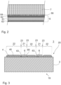
- Fig. 2 shows an example of a composite of carrier film 7 and film 6.
- the film 6 can in turn be a composite with several layers.
- a metallization 62 on a film layer 61 is particularly preferred.
- the metallization 62 can be covered by a cover layer 64.
- An adhesive layer 63 is provided on one side of the film 6. This can be designed as a heat-sealing layer, among other things, and bonds the film 6 to a base under the influence of temperature and pressure.
- the film 6 is attached to the carrier film 7 with a release agent 59. This enables it to be fixed to the carrier film on the one hand, and also to be removed when the adhesive layer 63 is connected to the substrate on the other.
- a suitable release agent is, for example, a wax layer.
- Fig. 3 a cross-section of a printed product 3 as obtainable with the invention is shown.
- the printed product 3 which can be produced using a method or device according to the invention, has a lacquer layer 40 on one side 20 of the substrate 2, the lacquer layer 40 covering the surface of the side 20 of the substrate 2 in regions, so that at least one region 22 is coated with the lacquer layer 40 and at least one adjacent region 21 of the side 20 is free of the lacquer layer 40, the lacquer layer 40 being raised so that the surface of the adjacent region 21 is lower than the surface of the lacquer layer 40, and a film 6 being applied to the substrate 2 and connected to it in this adjacent region 21, the edge 60 of the film 6 being located at the boundary 23 between the coated region 22 and the adjacent uncoated region 21.
- the surface of the printed product is therefore provided with alternating areas that are either coated with the varnish 4 or laminated with the film 6.
- the manufacturing process ensures that the film 6 fits precisely into the shape of the uncoated areas 21.
- this printed product compared to, for example, the process according to the US 2010/0212821 A1 new design options. For example, in processes in which the film is applied to a lacquer layer and connected to the lacquer layer, the film itself is raised. However, if the film 6 and the lacquer layer are applied next to one another and adjacent to one another, a relief structure can also be compensated.
- the film 6 at least reduces the height difference between the surface of the lacquer layer 40 and the surface of the base 2 in the uncoated area 21, or even completely compensates for it, so that an essentially flat surface is created. If the lacquer layer according to a further embodiment of the invention has a greater layer thickness than the thickness of the film 6, an effect can also be created that can otherwise only be created by embossing the film. As already mentioned, the invention can also be used in particular for metallized films. In this case, an appearance is obtained in which metallized and lacquered areas directly border one another.
- the layer thickness of the lacquer layer 40 is in the range from 1 to 100 micrometers, particularly preferably 2 to 50 micrometers.
- the film 6 can also be thicker than the lacquer layer 40, so that the surface of the film 6 is higher than the surface of the lacquer layer 40, or so that the film elements form raised areas.
- the part of the film 6 that is not glued to the substrate 2 can also be used for print finishing.
- the lacquer pattern on the substrate is used to apply a film shaped like the lacquer pattern to another substrate. The other substrate can then form the actual finished printed product.
- the method is based on a substrate 2 being partially coated on one side 20 with a lacquer 4 in such a way that at least one coated area 22 and at least one uncoated area 21 is present on the side 20, and the film 6 is then applied to the side coated with the lacquer 4 and glued to the substrate, wherein the film 6 is designed in such a way that it is bonded to the material of the substrate, but not to the paint, so that the bonding of the film is carried out selectively in at least one uncoated area 21, and wherein the film is separated after bonding at the dividing line between the coated and uncoated area.
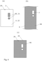
- Partial image (a) of the Fig. 4 shows the base 2 provided with the film 6 in some areas.
- This second, complementary part 66 is shown in part image (b).
- this part 66 of the film 6 is then at least partially bonded to a further base 25, so that the further base 25 has areas 66 provided with film 6, which are at least partially complementary to the areas 65 provided with film of the base 2 forming the auxiliary substrate.
- This complementarily patterned base 25 is shown in partial image (c).
- the film is applied to a carrier film as already described, whereby the carrier film 7 is pressed onto the base 2 with the side on which the film 6 is arranged in order to bond the film 6. If the surface of the film can now be over-embossed several times with the same film, one and the same auxiliary substrate can be used several times. Then, in a first step, the still unused film on the auxiliary substrate is freed from the unpainted areas of the film 6 and, in a second step, the remaining part of the film 6 is transferred from the carrier film 7 to the substrate to be finished.
- the auxiliary substrate can be permanently installed in a station in a machine provided for this purpose and the film is always moved by the format length, pre-structured on the auxiliary substrate, moved to the next station and the target substrate is finished there.
- a cliché for film finishing can be produced and used inexpensively in this way, particularly for small runs.
- the film 6 is glued to the carrier film 7 by pressing it onto the base 2.
- the carrier film 7 also forms the base, which in turn is the auxiliary substrate here.
- the film 6 is transferred to another area of the carrier film. In this other area, no further film 6 is expediently present.
- This other area can, for example, be the area not covered by the film 6. provided back of the carrier film.
- the other area is an area where the film 6 has previously been removed by transfer.
- the method according to these embodiments therefore provides that the film is transferred from a carrier film to the further substrate 25, wherein the carrier film has a first surface section which is provided with the film 6 and a second surface section not provided with film 6, wherein the second surface section of the carrier film 7 is partially coated with the varnish, so that at least one coated area 22 and at least one uncoated area 21 is present on this surface section, and wherein the film is transferred from the first surface section to the second surface section at its uncoated area 21, so that part of the film remains on the first surface section, and wherein the remaining film on the first surface section is then glued to the further substrate 25.
- Fig. 5 shows a device with which documents 25 according to this embodiment can be provided with a film 6.
- the film 6 is as in the Fig. 1 shown embodiment is applied to a carrier film 7.
- the carrier film 7 simultaneously represents the base 2, which is coated with lacquer 4, namely on the side of the carrier film 7 not provided with film 6.
- the opposite sides of the carrier film 7 thus form a first surface section 70 with film 6 and a second surface section 71 without film.
- the coating with lacquer 4 takes place as in the Fig. 1 shown embodiment with an inkjet print head 9.
- the carrier film 7 is guided over several rollers 27 so that the two sides, i.e. the surface sections 70, face each other.
- the two surface sections 70, 71 are pressed together with a pressure roller 17 and the film 6 is transferred to the second surface section 71 in the areas that are not provided with varnish 4 or the varnish layer 40.
- the carrier film 7 with the film 6 transferred to the second surface section 71 is then pressed and transferred to the other documents 25 transported by the conveyor belt 15 by means of a further pressure roller.
- the documents transported by the conveyor belt can be printed products and/or sheets of paper or cardboard.
- a pattern of the film 6 is produced on the further base 25, which corresponds to the pattern of the varnish 4 on the base 2, or here specifically the carrier film 7.
- the device 1 is thus generally designed, without limitation to the example shown in this embodiment, to apply the carrier film 7 to to provide a second surface section 71 not provided with film 6 with a lacquer layer 40 and to transfer the film 6 from a first surface section 70 provided with film 6 to the second surface section 71 to its areas not provided with lacquer 4. Then, as explained, the device 1 can also be further configured to transfer this transferred film 6 to a further substrate 25, in particular a printed product and/or a sheet of paper or cardboard.
- Both embodiments can also be combined with one another by transferring the film 6 to the substrates 2 in two steps.
- the substrates 2 are provided with varnish, so that part of the film 6 is transferred to the areas not coated with varnish.
- another part of the film is transferred to further substrates. If these further substrates do not have a varnish layer that prevents the transfer, a complementary pattern of the film then results on these further substrates.
- Such multiple and in particular complementary transfer is advantageous because the film 6 provided on the carrier film 7 can be used completely or at least to a large extent.
- the film 6 can also be partially transferred to an auxiliary substrate in the first step and then the remaining areas can be transferred to the base 25 in a second step, as shown in the example.
Landscapes
- Printing Methods (AREA)
- Laminated Bodies (AREA)
- Lining Or Joining Of Plastics Or The Like (AREA)
Claims (15)
- Procédé pour l'amélioration de produits imprimés, selon lequel un support (2) est revêtu partiellement sur une face (20) d'un vernis (4) durcissant par rayonnement, de telle sorte qu'au moins une zone (22) revêtue et au moins une zone (21) non revêtue est présente sur la face (20), et dans lequel un film (6) est ensuite appliqué sur la face (20) revêtue du vernis (4) et collé au support (2), dans lequel le film (6) est réalisé de sorte que celui-ci colle au matériau du support, mais pas au vernis (4), de sorte que le collage du film (4) s'effectue sélectivement dans l'au moins une zone (21) non revêtue, et dans lequel le film (4) après collage est séparé sur la ligne de séparation (23) entre la zone revêtue et non revêtue (21, 22), de sorte qu'un support (2) est obtenu, lequel présente au moins une zone (22) revêtue de vernis (4) d'une face (20) et une zone (21) voisine, non revêtue de ce vernis (4), dans lequel dans cette zone non revêtue du vernis (4) un film (6) est collé au support, dont le bord (60) est adjacent à la zone (22) revêtue de vernis (4) et un papier ou un carton est utilisé comme support (2).
- Procédé selon la revendication précédente, caractérisé en ce que le film (6) est appliqué sur un film de support (7), dans lequel pour coller le film (6) le film de support (7) est pressé sur le support (2) avec la face sur laquelle le film (6) est disposé.
- Procédé selon l'une quelconque des revendications précédentes, caractérisé en ce qu'au moins deux vernis (4, 5) différents sont utilisés, qui sont appliqués sur des zones (22) différentes de la face (20) du support (2).
- Procédé selon l'une quelconque des revendications précédentes, caractérisé en ce que le revêtement partiel du support (2) d'un vernis (4) s'effectue par éjection de gouttelettes du vernis (4) à partir d'une tête d'impression à jet d'encre (9) en réponse à des signaux de commande d'un système de commande (8), pendant que le support (2) est déplacé par rapport à la tête d'impression à jet d'encre (9).
- Procédé selon l'une quelconque des revendications précédentes, caractérisé en ce que le revêtement du support (2) s'effectue avec un vernis au moyen d'au moins un des procédés flexographie, tampographie, impression en creux ou sérigraphie.
- Procédé selon l'une quelconque des revendications précédentes, selon lequel le support (2) forme un substrat auxiliaire et la partie du film (6) non collée au support (2) est collée au moins partiellement à un autre support (25), de sorte que l'autre support présente des zones (66) pourvues d'un film, qui sont au moins partiellement complémentaires des zones (65) pourvues d'un film du support (2) formant un substrat auxiliaire et dans lequel de préférence le film (6) est transféré à partir d'un film de support (7) sur l'autre support (25), dans lequel le film de support (7) présente une première section de surface (70), qui est pourvue du film (6), ainsi qu'une deuxième section de surface (71), non pourvue du film (6), dans lequel la deuxième section de surface (71) du film de support (7) est revêtue partiellement du vernis (4), de sorte qu'au moins une zone (22) revêtue et au moins une zone (21) non revêtue est présente sur cette section de surface (71), et dans lequel le film (6) est transféré à partir de la première section de surface (70) sur la deuxième section de surface (71) sur la zone (21) non revêtue de celui-ci, de sorte qu'une partie du film (6) reste sur la première section de surface (70), et dans lequel le film restant est ensuite collé sur la première section de surface avec l'autre support (25) .
- Dispositif pour l'amélioration de produits imprimés, en particulier pour la mise en œuvre du procédé selon l'une quelconque des revendications précédentes, comprenant- un système pour revêtir partiellement une face (20) d'un papier ou carton comme support (2) pour un produit imprimé avec un vernis (4) durcissant par rayonnement, de sorte qu'au moins une zone (22) revêtue et au moins une zone (21) non revêtue est présente sur la face (20),- une source de lumière ultraviolette pour solidifier le vernis (4) en une couche de vernis, un- film (6) à coller au support, ainsi qu'un- système pour appliquer et coller le film (6) au support (2) sur la face (20) revêtue du vernis (4),- dans lequel le film (6) est réalisé de sorte que celui-ci colle au matériau du support (2), mais pas au vernis (4), de sorte que le collage du film (4) s'effectue sélectivement dans l'au moins une zone (21) non revêtue, ainsi que- un système, afin de séparer le film (6) après collage sur la limite (23) entre la zone revêtue et non revêtue (21, 22), de sorte qu'un support (2) d'un produit imprimé est obtenu, lequel présente au moins une zone (22) revêtue de vernis (4) d'une face (20) et une zone (21) voisine, non revêtue de ce vernis (4), dans lequel dans cette zone non revêtue du vernis (4) un film (6) est collé au support, dont le bord (60) est adjacent à la zone (22) revêtue de vernis (4).
- Dispositif selon l'une quelconque des revendications précédentes, caractérisé en ce
que le système pour revêtir partiellement une face (20) d'un support (2) comprend une tête d'impression à jet d'encre (9), laquelle délivre le vernis (4) par gouttes sur le support (2)en réponse à des signaux de commande d'un système de commande (8). - Dispositif selon l'une quelconque des revendications précédentes, caractérisé en ce
que le dispositif présente un système, afin de presser un film de support (7), sur lequel le film (6) est appliqué, sur le support (2), afin de transférer le film (6) à partir du film de support (7) sur le support (2). - Dispositif selon la revendication précédente, conçu pour pourvoir le film de support (7) sur une deuxième section de surface (71) non pourvue du film (6) d'une couche de vernis (40) et pour transférer le film (6) à partir d'une première section de surface (70) pourvue du film (6) sur la deuxième section de surface (71) sur les zones de celle-ci non pourvues de vernis (4).
- Produit imprimé (3), pouvant être fabriqué avec un procédé ou un dispositif selon l'une quelconque des revendications précédentes, avec une couche de vernis (40) durcie par rayonnement sur une face (20) d'un support (2), dans lequel la couche de vernis (40) recouvre par endroits la surface de la face (20) du support (2), de sorte qu'au moins une zone (22) est revêtue de la couche de vernis (40) et au moins une zone (21) adjacente de la face (20) est exempte de la couche de vernis (40), dans lequel la couche de vernis (40) est saillante, de sorte que la surface de la zone (21) voisine se situe plus bas que la surface de la couche de vernis (40), dans lequel dans cette zone (21) voisine un film (6) est appliqué sur le support (2) et est relié à celui-ci, dans lequel le bord (60) du film (6) se situe à la limite (23) entre la zone (22) revêtue et la zone (21) non revêtue voisine et dans lequel le support (2) est un papier ou un carton.
- Produit imprimé (3) selon la revendication précédente, caractérisé en ce que le film (6) au moins diminue la différence de hauteur entre la surface de la couche de vernis (40) et la surface du support (2) dans la zone (21) non revêtue.
- Produit imprimé (3) selon l'une des deux revendications précédentes, caractérisé en ce que le film (6) est plus épais que la couche de vernis (40), de sorte que la surface du film (6) se situe plus haut que la surface de la couche de vernis (40).
- Produit imprimé (3) selon l'une des deux revendications précédentes, caractérisé en ce que le film (6) est métallisé.
- Produit imprimé (3) selon l'une des deux revendications précédentes, caractérisé en ce que l'épaisseur de couche de la couche de vernis (40) se situe dans la plage de 1 à 100 micromètres.
Applications Claiming Priority (2)
| Application Number | Priority Date | Filing Date | Title |
|---|---|---|---|
| DE102018115748.7A DE102018115748A1 (de) | 2018-06-29 | 2018-06-29 | Verfahren und Vorrichtung zur Druckveredelung |
| PCT/EP2019/065804 WO2020002010A1 (fr) | 2018-06-29 | 2019-06-17 | Procédé et dispositif d'amélioration de produits imprimés |
Publications (2)
| Publication Number | Publication Date |
|---|---|
| EP3814149A1 EP3814149A1 (fr) | 2021-05-05 |
| EP3814149B1 true EP3814149B1 (fr) | 2025-02-19 |
Family
ID=67001762
Family Applications (1)
| Application Number | Title | Priority Date | Filing Date |
|---|---|---|---|
| EP19732574.9A Active EP3814149B1 (fr) | 2018-06-29 | 2019-06-17 | Procédé et dispositif d'amélioration de produits imprimés |
Country Status (6)
| Country | Link |
|---|---|
| US (1) | US12168364B2 (fr) |
| EP (1) | EP3814149B1 (fr) |
| CN (1) | CN112423994B (fr) |
| DE (1) | DE102018115748A1 (fr) |
| ES (1) | ES3024133T3 (fr) |
| WO (1) | WO2020002010A1 (fr) |
Families Citing this family (1)
| Publication number | Priority date | Publication date | Assignee | Title |
|---|---|---|---|---|
| EP4167132A1 (fr) * | 2021-10-15 | 2023-04-19 | Thales Dis France SAS | Carte de feuille métallique et son procédé de fabrication |
Family Cites Families (9)
| Publication number | Priority date | Publication date | Assignee | Title |
|---|---|---|---|---|
| DE4440762C1 (de) | 1994-11-15 | 1996-04-04 | Borsi Kg F | Verfahren zum selektiven, bereichsweisen Beschichten einer transparenten Trägerlatte |
| MY129788A (en) | 1996-01-25 | 2007-04-30 | Innovia Films Ltd | Printable film. |
| DE19951404B4 (de) * | 1999-10-26 | 2006-06-14 | Westiform Gmbh & Co. Kg | Verfahren zur Herstellung der Deckplatte einer Leuchtreklame |
| DE10224128A1 (de) | 2002-05-29 | 2003-12-18 | Schmid Rhyner Ag Adliswil | Verfahren zum Auftrag von Beschichtungen auf Oberflächen |
| US20050255275A1 (en) * | 2004-05-14 | 2005-11-17 | Downs John P | Adhesive dispensing tape including a transparent carrier material |
| US20100212821A1 (en) | 2007-09-24 | 2010-08-26 | Scodix, Ltd. | System and method for cold foil relief production |
| DE102009001221A1 (de) * | 2009-02-27 | 2010-09-02 | Evonik Degussa Gmbh | Druckverfahren zur Herstellung individualisierter elektrischer und/oder elektronischer Strukturen |
| CN103717387B (zh) | 2011-08-03 | 2017-11-07 | 印刷包装国际公司 | 用于形成带图案化微波能量相互作用材料的层叠件的系统和方法 |
| DE102012218022B4 (de) * | 2011-10-28 | 2023-06-15 | manroland sheetfed GmbH | Betrieb eines Kaltfolienaggregates mit einem Druckwerk |
-
2018
- 2018-06-29 DE DE102018115748.7A patent/DE102018115748A1/de active Pending
-
2019
- 2019-06-17 US US17/256,486 patent/US12168364B2/en active Active
- 2019-06-17 WO PCT/EP2019/065804 patent/WO2020002010A1/fr not_active Ceased
- 2019-06-17 ES ES19732574T patent/ES3024133T3/es active Active
- 2019-06-17 CN CN201980044082.0A patent/CN112423994B/zh active Active
- 2019-06-17 EP EP19732574.9A patent/EP3814149B1/fr active Active
Also Published As
| Publication number | Publication date |
|---|---|
| US20210221164A1 (en) | 2021-07-22 |
| US12168364B2 (en) | 2024-12-17 |
| CN112423994B (zh) | 2022-06-07 |
| CN112423994A (zh) | 2021-02-26 |
| ES3024133T3 (en) | 2025-06-03 |
| WO2020002010A1 (fr) | 2020-01-02 |
| BR112020025553A2 (pt) | 2021-03-16 |
| DE102018115748A1 (de) | 2020-01-02 |
| EP3814149A1 (fr) | 2021-05-05 |
Similar Documents
| Publication | Publication Date | Title |
|---|---|---|
| EP3370973B1 (fr) | Rocédé d'application permettant d'appliquer une couche de transfert d'un film sur un substrat | |
| EP3274174B1 (fr) | Procédé et dispositif d'application d'une feuille | |
| EP3390069B1 (fr) | Procédé de fabrication d'un élément de sécurité et film de transfert | |
| EP2938496B1 (fr) | Procédé et dispositif d'estampage à froid sur des objets tridimensionnels | |
| EP1940618B1 (fr) | Procede de transfert d'un corps multicouche et feuille de transfert | |
| EP3802144A1 (fr) | Procédé de fabrication d'un élément stratifié et d'un film stratifié ainsi qu'élément stratifié et film stratifié | |
| WO1997030855A1 (fr) | Film de transfert et son procede de production | |
| EP2981419A1 (fr) | Procédé servant à fabriquer un élément de sécurité pourvu d'une inscription négative | |
| EP3111280B1 (fr) | Procédé de fabrication de documents de sécurité | |
| EP3580033A1 (fr) | Procédé de fabrication d'une pièce moulée en matière plastique présentant une surface décorée ainsi que pièce moulée en matière plastique présentant une surface décorée | |
| DE102018112652A1 (de) | Verfahren zur Herstellung eines Laminatkörpers und einer Laminierfolie sowie Laminatkörper und Laminierfolie | |
| EP2011642A2 (fr) | Produit d'impression laminé et son procédé de fabrication | |
| EP3894232B1 (fr) | Procédé de fabrication d'un produit intermédiaire de feuille, produit intermédiaire de feuille ainsi que procédé de fabrication d'un produit | |
| EP2821218B1 (fr) | Procédé de fabrication d'un étiquette adhésive composite imprimée | |
| EP4028261B1 (fr) | Procédé et dispositif de finition d'épreuves | |
| DE102015118841A1 (de) | Verfahren und Applikationsvorrichtung zum Applizieren einer Übertragungslage einer Folie auf ein Substrat | |
| EP3814149A1 (fr) | Procédé et dispositif d'amélioration de produits imprimés | |
| DE102007031001A1 (de) | Bogenrotationsdruckmaschine | |
| EP1390214B1 (fr) | Feuille d'estampage, procede pour sa production et pour le transfert d'une etiquette de la feuille d'estampage sur un substrat | |
| DE4411404B4 (de) | Schichtverbund zum Übertragen von optisch variablen Einzelelementen auf zu sichernde Gegenstände, Sicherheitsdokument und ein Verfahren zur Herstellung eines Schichtverbunds | |
| DE102008043312A1 (de) | Transferdruckverfahren | |
| EP4067103B1 (fr) | Procédé de fabrication pour un élément de sécurité optiquement variable | |
| EP4067104B1 (fr) | Procédé de fabrication pour un élément de sécurité optiquement variable | |
| DE19840981A1 (de) | Verfahren und Vorrichtung zum Herstellen bedruckter und geprägter Teile | |
| EP4214063A1 (fr) | Matériau de transfert d'éléments de sécurité permettant le transfert, dans un bon registre, d'éléments de sécurité à des documents de valeur |
Legal Events
| Date | Code | Title | Description |
|---|---|---|---|
| STAA | Information on the status of an ep patent application or granted ep patent |
Free format text: STATUS: UNKNOWN |
|
| STAA | Information on the status of an ep patent application or granted ep patent |
Free format text: STATUS: THE INTERNATIONAL PUBLICATION HAS BEEN MADE |
|
| PUAI | Public reference made under article 153(3) epc to a published international application that has entered the european phase |
Free format text: ORIGINAL CODE: 0009012 |
|
| STAA | Information on the status of an ep patent application or granted ep patent |
Free format text: STATUS: REQUEST FOR EXAMINATION WAS MADE |
|
| 17P | Request for examination filed |
Effective date: 20210105 |
|
| AK | Designated contracting states |
Kind code of ref document: A1 Designated state(s): AL AT BE BG CH CY CZ DE DK EE ES FI FR GB GR HR HU IE IS IT LI LT LU LV MC MK MT NL NO PL PT RO RS SE SI SK SM TR |
|
| RAP3 | Party data changed (applicant data changed or rights of an application transferred) |
Owner name: ACTEGA SCHMID RHYNER AG |
|
| DAV | Request for validation of the european patent (deleted) | ||
| DAX | Request for extension of the european patent (deleted) | ||
| STAA | Information on the status of an ep patent application or granted ep patent |
Free format text: STATUS: EXAMINATION IS IN PROGRESS |
|
| 17Q | First examination report despatched |
Effective date: 20230131 |
|
| GRAP | Despatch of communication of intention to grant a patent |
Free format text: ORIGINAL CODE: EPIDOSNIGR1 |
|
| STAA | Information on the status of an ep patent application or granted ep patent |
Free format text: STATUS: GRANT OF PATENT IS INTENDED |
|
| INTG | Intention to grant announced |
Effective date: 20240918 |
|
| GRAS | Grant fee paid |
Free format text: ORIGINAL CODE: EPIDOSNIGR3 |
|
| GRAA | (expected) grant |
Free format text: ORIGINAL CODE: 0009210 |
|
| STAA | Information on the status of an ep patent application or granted ep patent |
Free format text: STATUS: THE PATENT HAS BEEN GRANTED |
|
| AK | Designated contracting states |
Kind code of ref document: B1 Designated state(s): AL AT BE BG CH CY CZ DE DK EE ES FI FR GB GR HR HU IE IS IT LI LT LU LV MC MK MT NL NO PL PT RO RS SE SI SK SM TR |
|
| REG | Reference to a national code |
Ref country code: GB Ref legal event code: FG4D Free format text: NOT ENGLISH |
|
| REG | Reference to a national code |
Ref country code: CH Ref legal event code: EP |
|
| REG | Reference to a national code |
Ref country code: IE Ref legal event code: FG4D Free format text: LANGUAGE OF EP DOCUMENT: GERMAN |
|
| REG | Reference to a national code |
Ref country code: DE Ref legal event code: R096 Ref document number: 502019012958 Country of ref document: DE |
|
| REG | Reference to a national code |
Ref country code: ES Ref legal event code: FG2A Ref document number: 3024133 Country of ref document: ES Kind code of ref document: T3 Effective date: 20250603 |
|
| REG | Reference to a national code |
Ref country code: NL Ref legal event code: MP Effective date: 20250219 |
|
| PG25 | Lapsed in a contracting state [announced via postgrant information from national office to epo] |
Ref country code: RS Free format text: LAPSE BECAUSE OF FAILURE TO SUBMIT A TRANSLATION OF THE DESCRIPTION OR TO PAY THE FEE WITHIN THE PRESCRIBED TIME-LIMIT Effective date: 20250519 |
|
| PG25 | Lapsed in a contracting state [announced via postgrant information from national office to epo] |
Ref country code: FI Free format text: LAPSE BECAUSE OF FAILURE TO SUBMIT A TRANSLATION OF THE DESCRIPTION OR TO PAY THE FEE WITHIN THE PRESCRIBED TIME-LIMIT Effective date: 20250219 |
|
| PG25 | Lapsed in a contracting state [announced via postgrant information from national office to epo] |
Ref country code: PL Free format text: LAPSE BECAUSE OF FAILURE TO SUBMIT A TRANSLATION OF THE DESCRIPTION OR TO PAY THE FEE WITHIN THE PRESCRIBED TIME-LIMIT Effective date: 20250219 |
|
| PGFP | Annual fee paid to national office [announced via postgrant information from national office to epo] |
Ref country code: DE Payment date: 20250618 Year of fee payment: 7 |
|
| PGFP | Annual fee paid to national office [announced via postgrant information from national office to epo] |
Ref country code: GB Payment date: 20250620 Year of fee payment: 7 |
|
| REG | Reference to a national code |
Ref country code: LT Ref legal event code: MG9D |
|
| PG25 | Lapsed in a contracting state [announced via postgrant information from national office to epo] |
Ref country code: NO Free format text: LAPSE BECAUSE OF FAILURE TO SUBMIT A TRANSLATION OF THE DESCRIPTION OR TO PAY THE FEE WITHIN THE PRESCRIBED TIME-LIMIT Effective date: 20250519 Ref country code: IS Free format text: LAPSE BECAUSE OF FAILURE TO SUBMIT A TRANSLATION OF THE DESCRIPTION OR TO PAY THE FEE WITHIN THE PRESCRIBED TIME-LIMIT Effective date: 20250619 |
|
| PG25 | Lapsed in a contracting state [announced via postgrant information from national office to epo] |
Ref country code: NL Free format text: LAPSE BECAUSE OF FAILURE TO SUBMIT A TRANSLATION OF THE DESCRIPTION OR TO PAY THE FEE WITHIN THE PRESCRIBED TIME-LIMIT Effective date: 20250219 |
|
| PG25 | Lapsed in a contracting state [announced via postgrant information from national office to epo] |
Ref country code: HR Free format text: LAPSE BECAUSE OF FAILURE TO SUBMIT A TRANSLATION OF THE DESCRIPTION OR TO PAY THE FEE WITHIN THE PRESCRIBED TIME-LIMIT Effective date: 20250219 |
|
| PG25 | Lapsed in a contracting state [announced via postgrant information from national office to epo] |
Ref country code: LV Free format text: LAPSE BECAUSE OF FAILURE TO SUBMIT A TRANSLATION OF THE DESCRIPTION OR TO PAY THE FEE WITHIN THE PRESCRIBED TIME-LIMIT Effective date: 20250219 Ref country code: PT Free format text: LAPSE BECAUSE OF FAILURE TO SUBMIT A TRANSLATION OF THE DESCRIPTION OR TO PAY THE FEE WITHIN THE PRESCRIBED TIME-LIMIT Effective date: 20250620 |
|
| PGFP | Annual fee paid to national office [announced via postgrant information from national office to epo] |
Ref country code: FR Payment date: 20250626 Year of fee payment: 7 |
|
| PG25 | Lapsed in a contracting state [announced via postgrant information from national office to epo] |
Ref country code: GR Free format text: LAPSE BECAUSE OF FAILURE TO SUBMIT A TRANSLATION OF THE DESCRIPTION OR TO PAY THE FEE WITHIN THE PRESCRIBED TIME-LIMIT Effective date: 20250520 Ref country code: BG Free format text: LAPSE BECAUSE OF FAILURE TO SUBMIT A TRANSLATION OF THE DESCRIPTION OR TO PAY THE FEE WITHIN THE PRESCRIBED TIME-LIMIT Effective date: 20250219 |
|
| PG25 | Lapsed in a contracting state [announced via postgrant information from national office to epo] |
Ref country code: SE Free format text: LAPSE BECAUSE OF FAILURE TO SUBMIT A TRANSLATION OF THE DESCRIPTION OR TO PAY THE FEE WITHIN THE PRESCRIBED TIME-LIMIT Effective date: 20250219 |
|
| PG25 | Lapsed in a contracting state [announced via postgrant information from national office to epo] |
Ref country code: SM Free format text: LAPSE BECAUSE OF FAILURE TO SUBMIT A TRANSLATION OF THE DESCRIPTION OR TO PAY THE FEE WITHIN THE PRESCRIBED TIME-LIMIT Effective date: 20250219 |
|
| PGFP | Annual fee paid to national office [announced via postgrant information from national office to epo] |
Ref country code: ES Payment date: 20250718 Year of fee payment: 7 |
|
| PG25 | Lapsed in a contracting state [announced via postgrant information from national office to epo] |
Ref country code: DK Free format text: LAPSE BECAUSE OF FAILURE TO SUBMIT A TRANSLATION OF THE DESCRIPTION OR TO PAY THE FEE WITHIN THE PRESCRIBED TIME-LIMIT Effective date: 20250219 |
|
| PGFP | Annual fee paid to national office [announced via postgrant information from national office to epo] |
Ref country code: IT Payment date: 20250630 Year of fee payment: 7 |
|
| PG25 | Lapsed in a contracting state [announced via postgrant information from national office to epo] |
Ref country code: CZ Free format text: LAPSE BECAUSE OF FAILURE TO SUBMIT A TRANSLATION OF THE DESCRIPTION OR TO PAY THE FEE WITHIN THE PRESCRIBED TIME-LIMIT Effective date: 20250219 Ref country code: EE Free format text: LAPSE BECAUSE OF FAILURE TO SUBMIT A TRANSLATION OF THE DESCRIPTION OR TO PAY THE FEE WITHIN THE PRESCRIBED TIME-LIMIT Effective date: 20250219 |
|
| PG25 | Lapsed in a contracting state [announced via postgrant information from national office to epo] |
Ref country code: RO Free format text: LAPSE BECAUSE OF FAILURE TO SUBMIT A TRANSLATION OF THE DESCRIPTION OR TO PAY THE FEE WITHIN THE PRESCRIBED TIME-LIMIT Effective date: 20250219 |
|
| PG25 | Lapsed in a contracting state [announced via postgrant information from national office to epo] |
Ref country code: SK Free format text: LAPSE BECAUSE OF FAILURE TO SUBMIT A TRANSLATION OF THE DESCRIPTION OR TO PAY THE FEE WITHIN THE PRESCRIBED TIME-LIMIT Effective date: 20250219 |
|
| REG | Reference to a national code |
Ref country code: DE Ref legal event code: R097 Ref document number: 502019012958 Country of ref document: DE |
|
| PLBE | No opposition filed within time limit |
Free format text: ORIGINAL CODE: 0009261 |
|
| STAA | Information on the status of an ep patent application or granted ep patent |
Free format text: STATUS: NO OPPOSITION FILED WITHIN TIME LIMIT |
|
| REG | Reference to a national code |
Ref country code: CH Ref legal event code: L10 Free format text: ST27 STATUS EVENT CODE: U-0-0-L10-L00 (AS PROVIDED BY THE NATIONAL OFFICE) Effective date: 20251231 |
|
| REG | Reference to a national code |
Ref country code: CH Ref legal event code: H13 Free format text: ST27 STATUS EVENT CODE: U-0-0-H10-H13 (AS PROVIDED BY THE NATIONAL OFFICE) Effective date: 20260127 |
|
| 26N | No opposition filed |
Effective date: 20251120 |
|
| PG25 | Lapsed in a contracting state [announced via postgrant information from national office to epo] |
Ref country code: MC Free format text: LAPSE BECAUSE OF FAILURE TO SUBMIT A TRANSLATION OF THE DESCRIPTION OR TO PAY THE FEE WITHIN THE PRESCRIBED TIME-LIMIT Effective date: 20250219 |
|
| PG25 | Lapsed in a contracting state [announced via postgrant information from national office to epo] |
Ref country code: LU Free format text: LAPSE BECAUSE OF NON-PAYMENT OF DUE FEES Effective date: 20250617 |
|
| REG | Reference to a national code |
Ref country code: BE Ref legal event code: MM Effective date: 20250630 |
|
| PG25 | Lapsed in a contracting state [announced via postgrant information from national office to epo] |
Ref country code: IE Free format text: LAPSE BECAUSE OF NON-PAYMENT OF DUE FEES Effective date: 20250617 |
|
| PG25 | Lapsed in a contracting state [announced via postgrant information from national office to epo] |
Ref country code: BE Free format text: LAPSE BECAUSE OF NON-PAYMENT OF DUE FEES Effective date: 20250630 |
|
| PG25 | Lapsed in a contracting state [announced via postgrant information from national office to epo] |
Ref country code: CH Free format text: LAPSE BECAUSE OF NON-PAYMENT OF DUE FEES Effective date: 20250630 |