EP3814459B1 - Allume-feu - Google Patents
Allume-feu Download PDFInfo
- Publication number
- EP3814459B1 EP3814459B1 EP19705789.6A EP19705789A EP3814459B1 EP 3814459 B1 EP3814459 B1 EP 3814459B1 EP 19705789 A EP19705789 A EP 19705789A EP 3814459 B1 EP3814459 B1 EP 3814459B1
- Authority
- EP
- European Patent Office
- Prior art keywords
- fuel elements
- container
- spaced apart
- pair
- stack
- Prior art date
- Legal status (The legal status is an assumption and is not a legal conclusion. Google has not performed a legal analysis and makes no representation as to the accuracy of the status listed.)
- Active
Links
Images



Classifications
-
- F—MECHANICAL ENGINEERING; LIGHTING; HEATING; WEAPONS; BLASTING
- F23—COMBUSTION APPARATUS; COMBUSTION PROCESSES
- F23Q—IGNITION; EXTINGUISHING-DEVICES
- F23Q13/00—Igniters not otherwise provided for
- F23Q13/04—Igniters not otherwise provided for using portable burners, e.g. torches, fire pots
-
- C—CHEMISTRY; METALLURGY
- C10—PETROLEUM, GAS OR COKE INDUSTRIES; TECHNICAL GASES CONTAINING CARBON MONOXIDE; FUELS; LUBRICANTS; PEAT
- C10L—FUELS NOT OTHERWISE PROVIDED FOR; NATURAL GAS; SYNTHETIC NATURAL GAS OBTAINED BY PROCESSES NOT COVERED BY SUBCLASSES C10G OR C10K; LIQUIFIED PETROLEUM GAS; USE OF ADDITIVES TO FUELS OR FIRES; FIRE-LIGHTERS
- C10L11/00—Fire-lighters
- C10L11/04—Fire-lighters consisting of combustible material
-
- A—HUMAN NECESSITIES
- A47—FURNITURE; DOMESTIC ARTICLES OR APPLIANCES; COFFEE MILLS; SPICE MILLS; SUCTION CLEANERS IN GENERAL
- A47J—KITCHEN EQUIPMENT; COFFEE MILLS; SPICE MILLS; APPARATUS FOR MAKING BEVERAGES
- A47J37/00—Baking; Roasting; Grilling; Frying
- A47J37/06—Roasters; Grills; Sandwich grills
- A47J37/07—Roasting devices for outdoor use; Barbecues
- A47J37/0786—Accessories
- A47J37/079—Charcoal igniting devices
-
- B—PERFORMING OPERATIONS; TRANSPORTING
- B65—CONVEYING; PACKING; STORING; HANDLING THIN OR FILAMENTARY MATERIAL
- B65D—CONTAINERS FOR STORAGE OR TRANSPORT OF ARTICLES OR MATERIALS, e.g. BAGS, BARRELS, BOTTLES, BOXES, CANS, CARTONS, CRATES, DRUMS, JARS, TANKS, HOPPERS, FORWARDING CONTAINERS; ACCESSORIES, CLOSURES, OR FITTINGS THEREFOR; PACKAGING ELEMENTS; PACKAGES
- B65D5/00—Rigid or semi-rigid containers of polygonal cross-section, e.g. boxes, cartons or trays, formed by folding or erecting one or more blanks made of paper
- B65D5/42—Details of containers or of foldable or erectable container blanks
- B65D5/4295—Ventilating arrangements, e.g. openings, space elements
-
- B—PERFORMING OPERATIONS; TRANSPORTING
- B65—CONVEYING; PACKING; STORING; HANDLING THIN OR FILAMENTARY MATERIAL
- B65D—CONTAINERS FOR STORAGE OR TRANSPORT OF ARTICLES OR MATERIALS, e.g. BAGS, BARRELS, BOTTLES, BOXES, CANS, CARTONS, CRATES, DRUMS, JARS, TANKS, HOPPERS, FORWARDING CONTAINERS; ACCESSORIES, CLOSURES, OR FITTINGS THEREFOR; PACKAGING ELEMENTS; PACKAGES
- B65D5/00—Rigid or semi-rigid containers of polygonal cross-section, e.g. boxes, cartons or trays, formed by folding or erecting one or more blanks made of paper
- B65D5/42—Details of containers or of foldable or erectable container blanks
- B65D5/44—Integral, inserted or attached portions forming internal or external fittings
- B65D5/50—Internal supporting or protecting elements for contents
- B65D5/5028—Elements formed separately from the container body
- B65D5/5035—Paper elements
- B65D5/5047—Blocks
- B65D5/505—Blocks formed by folding up one or more blanks to form a hollow block
-
- C—CHEMISTRY; METALLURGY
- C10—PETROLEUM, GAS OR COKE INDUSTRIES; TECHNICAL GASES CONTAINING CARBON MONOXIDE; FUELS; LUBRICANTS; PEAT
- C10L—FUELS NOT OTHERWISE PROVIDED FOR; NATURAL GAS; SYNTHETIC NATURAL GAS OBTAINED BY PROCESSES NOT COVERED BY SUBCLASSES C10G OR C10K; LIQUIFIED PETROLEUM GAS; USE OF ADDITIVES TO FUELS OR FIRES; FIRE-LIGHTERS
- C10L11/00—Fire-lighters
- C10L11/06—Fire-lighters of a special shape
-
- C—CHEMISTRY; METALLURGY
- C10—PETROLEUM, GAS OR COKE INDUSTRIES; TECHNICAL GASES CONTAINING CARBON MONOXIDE; FUELS; LUBRICANTS; PEAT
- C10L—FUELS NOT OTHERWISE PROVIDED FOR; NATURAL GAS; SYNTHETIC NATURAL GAS OBTAINED BY PROCESSES NOT COVERED BY SUBCLASSES C10G OR C10K; LIQUIFIED PETROLEUM GAS; USE OF ADDITIVES TO FUELS OR FIRES; FIRE-LIGHTERS
- C10L5/00—Solid fuels
- C10L5/40—Solid fuels essentially based on materials of non-mineral origin
- C10L5/44—Solid fuels essentially based on materials of non-mineral origin on vegetable substances
- C10L5/442—Wood or forestry waste
-
- C—CHEMISTRY; METALLURGY
- C10—PETROLEUM, GAS OR COKE INDUSTRIES; TECHNICAL GASES CONTAINING CARBON MONOXIDE; FUELS; LUBRICANTS; PEAT
- C10L—FUELS NOT OTHERWISE PROVIDED FOR; NATURAL GAS; SYNTHETIC NATURAL GAS OBTAINED BY PROCESSES NOT COVERED BY SUBCLASSES C10G OR C10K; LIQUIFIED PETROLEUM GAS; USE OF ADDITIVES TO FUELS OR FIRES; FIRE-LIGHTERS
- C10L2230/00—Function and purpose of a components of a fuel or the composition as a whole
- C10L2230/06—Firelighters or wicks, as additive to a solid fuel
-
- Y—GENERAL TAGGING OF NEW TECHNOLOGICAL DEVELOPMENTS; GENERAL TAGGING OF CROSS-SECTIONAL TECHNOLOGIES SPANNING OVER SEVERAL SECTIONS OF THE IPC; TECHNICAL SUBJECTS COVERED BY FORMER USPC CROSS-REFERENCE ART COLLECTIONS [XRACs] AND DIGESTS
- Y02—TECHNOLOGIES OR APPLICATIONS FOR MITIGATION OR ADAPTATION AGAINST CLIMATE CHANGE
- Y02E—REDUCTION OF GREENHOUSE GAS [GHG] EMISSIONS, RELATED TO ENERGY GENERATION, TRANSMISSION OR DISTRIBUTION
- Y02E50/00—Technologies for the production of fuel of non-fossil origin
- Y02E50/10—Biofuels, e.g. bio-diesel
-
- Y—GENERAL TAGGING OF NEW TECHNOLOGICAL DEVELOPMENTS; GENERAL TAGGING OF CROSS-SECTIONAL TECHNOLOGIES SPANNING OVER SEVERAL SECTIONS OF THE IPC; TECHNICAL SUBJECTS COVERED BY FORMER USPC CROSS-REFERENCE ART COLLECTIONS [XRACs] AND DIGESTS
- Y02—TECHNOLOGIES OR APPLICATIONS FOR MITIGATION OR ADAPTATION AGAINST CLIMATE CHANGE
- Y02E—REDUCTION OF GREENHOUSE GAS [GHG] EMISSIONS, RELATED TO ENERGY GENERATION, TRANSMISSION OR DISTRIBUTION
- Y02E50/00—Technologies for the production of fuel of non-fossil origin
- Y02E50/30—Fuel from waste, e.g. synthetic alcohol or diesel
Definitions
- the present invention relates to apparatus for starting a fire.
- the present invention relates to apparatus for quickly, safely and efficiently lighting a fire for a variety of different applications.
- a conventional wood burning stove includes a closed metal firebox, typically steel or cast iron and lined with fire brick, which is connected to a suitable flue by a flue pipe, and one or more controls to selectively adjust the amount of air being drawn into the firebox during the combustion process.
- Such stoves are generally used to burn wood fuel, such as a logs or wood-derived biomass fuel, but also coal and/or peat to produce heat for heating and/or cooking.
- Lighting a wood burning stove typically involves arranging dry kindling on the grate or firebed of the stove and lighting the same using paper or firelighters to heat the firebox and warm the chimney to aid flue performance. Once the kindling is burning well, larger pieces of split wood are added to create a stable firebed followed by larger logs when an efficient and stable fire has been established.
- Other fire lighting methods include the 'top-down' method which involves creating a channel between a pair of spaced apart logs, locating paper or firelighters in the channel, and forming a bridge of kindling over the channel.
- many people continue to struggle to successfully light a fire, be it in a wood burning stove, a multifuel stove, an open fire, a barbecue, a pizza oven, a fire pit or a camp fire.
- a fire which is burning inefficiently from the start will produce excessive smoke, which wastes energy and causes air pollution, and the flue will become lined with creosote which is a significant fire hazard.
- Fire starters are known such as those described in CA2871765 , US2017/002284 and KR101694078 .
- apparatus for starting a fire comprising:
- the container comprises an openable portion configured to selectively provide the at least one aperture.
- the ignition element is located on an intermediate retaining element above a first spaced apart pair of the fuel elements located at a base region of the container.
- the first pair of spaced apart fuel elements are located in a base retaining element disposed on the base region of the container.
- the intermediate retaining element is supported between a second spaced apart pair of the fuel elements located on and oriented perpendicularly to the first pair of fuel elements.
- the intermediate retaining element defines a channel for locating the ignition element between the second pair of spaced apart fuel elements.
- the intermediate retaining element comprises a base portion and a pair of elongate retaining portions extending outwardly in opposed directions therefrom to engage and retain a respective one of the second fuel elements in a predetermined position and orientation within the container.
- further combustible fuel elements are located on the second layer to form further layers of the stack, the fuel elements of each layer being spaced apart and oriented substantially perpendicular to the fuel elements of adjacent layers.
- the apparatus comprises at least one further retaining element to prevent at least the fuel elements of the further layers from substantially moving with respect to each other and the container.
- the at least one further retaining element comprises a plurality of vertically oriented retaining portions located between the spaced apart fuel elements of the further layers.
- the at least one further retaining element comprises an upper portion from which each retaining portion extends and having at least one aperture therein.
- the at least one further retaining element is combustible.
- the container comprises at least one further aperture pre-formed or formable in a side wall thereof.
- the container comprises a lid having at least one hole pre-formed or formable therein.
- a method of assembling apparatus for starting a fire comprising:
- the supporting fuel elements are spaced apart and located on each side of the at least one aperture or an openable portion of the container configured to selectively provide the at least one aperture.
- the method comprises locating the ignition element on an intermediate retaining element above a first spaced apart pair of the fuel elements located on a base of the container.
- the method comprises supporting the intermediate retaining element between a second spaced apart pair of the fuel elements located on and oriented perpendicularly to the first pair of fuel elements.
- the method comprises locating further layers of said fuel elements on the second layer, the fuel elements of each further layer being spaced apart and oriented substantially perpendicular to the fuel elements of adjacent layers.
- the method comprises locating at least one further retaining element into the stack to prevent at least the fuel elements of the further layers from substantially moving with respect to each other and the container.
- the method comprises closing a lid of the container.
- a plurality of elongate and horizontally oriented wood-based fuel elements is arranged in a Jenga TM -style formation to form a cuboidal stack 100.
- Each fuel element is around 100mm to 120mm long and has a square cross section of around 20x20mm.
- each fuel element may be any suitable length and cross-sectional shape and size for a particular fire-lighting application.
- each fuel element is a soft wood such as pine, fir, or cedar, or the like.
- the stack 100 is sized and shaped to be located in a correspondingly sized and shaped combustible container, such as a cuboid box 200 as shown in Figure 2 , to thereby be securely contained therein to avoid excessive movement/collapse during transit, storage and use.
- the stack 100 comprises a pair of spaced apart and substantially parallel fuel elements 102,104 for locating in the base of the container 200 such that a window 202 in a side wall 204 of the container and proximal to the base 206 is located between the pair of base fuel elements 102,104.
- Supported on the base fuel elements 102,104 is a flammable ignition element 106, e.g.
- the flammable fuel element/accelerator 106 may comprise hexamine or may alternatively comprise natural constituents not derived from highly flammable material or petrochemical based elements.
- the flammable fuel element/accelerator 106 is substantially disc-shaped and has a diameter of around 100-120 mm and a thickness of around 6-8 mm, but it may be a different shape/size, such as square, rectangular, triangular, oval, or the like, or it may correspond in size/shape/cross section to the combustible fuel elements in the stack.
- a plurality, aptly three, spaced apart combustible wood-based fuel elements 108 are arranged on the flammable fuel element 106 and oriented substantially perpendicular with respect to the spaced apart base fuel elements 102,104. Further layers of spaced apart combustible fuel elements 110,112, aptly three in each layer, are provided to form the stack 100 wherein each layer of elements is oriented substantially perpendicularly with respect to its adjacent layer located below and above. The number of layers in the stack 100 may correspond with the height of the container 200.
- one or more substantially vertically oriented retaining elements 114 may be provided to pass through the gaps between the layers of horizontally arranged fuel elements.
- the retaining elements 114 may be combustible or non-combustible. They may be left in the stack or removed and discarded before the apparatus is used.
- the retaining elements 114 may be substantially combustible and removed from the stack before being placed on top of the stack in a substantially perpendicular orientation with respect to the fuel elements of the layer below to thereby form an uppermost layer of the stack.
- the container may be shaped to securely retain the fuel elements located therein to prevent them moving during transit, storage and use.
- one or more regions of the container may extend from an inner surface thereof to engage with the stack and prevent the same from moving/collapsing during transit, storage and use.
- at least one support element such as a collar or a sleeve, may engage around a portion of the stack to prevent the fuel elements from moving during transit, storage or use. Such a support element may be combustible and left in situ when lighting the apparatus or may be removed from the apparatus prior to lighting the apparatus.
- the combustible container 200 is aptly a box having an interior sized and shaped to correspond with the size and shape of the stack 100.
- the stack 100 may be arranged such that the combustible fuel elements 102,104, 108,110,112 and the flammable fuel element/s 106 are fixed together, e.g. by a suitable adhesive, such that the stack 100 may be lifted and lowered into the container during assembly thereof.
- the stack 100 may be arranged within the container by sequentially locating the individual components therein.
- the stack 100 is located in the container such that the window 202 is located between the pair of base fuel elements 102,104. This desirably allows a user to locate a naked flame, e.g.
- the window 202 also allows a sufficient amount of air to be efficiently drawn into the container and under the stack to ensure efficient and rapid ignition and combustion of the combustible fuel elements located above the flammable fuel element.
- Supporting the flammable fuel element/s 106 on at least one layer of support/base fuel elements 102,104 allows the stack to burn in a desirable 'top-down' method for longer combustion and efficient ignition of larger fuel elements later placed on the fire. This arrangement also allows air to flow from underneath and through the stack.
- the window 202 in the container 200 as illustrated in Figure 2 is substantially slotted and extends from a base edge region 208 into a side wall 204 and the base 206.
- the window 202 is aptly configured to allow access to the firelighter 106 using a conventional cigarette lighter so that the outside of the container does not need to be ignited to create the initial combustion of the stack. Furthermore, the window 202 serves to draw air into the container at this point to aid initial combustion of the firelighter and subsequently the fuel contained therein.
- the window 202 is located substantially centrally in the side wall and base. However, the window 202 may be located in the side wall 204 only and/or may be offset from centre. Further alternatively, a plurality of windows may be provided proximal the base of the container.
- a first window may be provided in a first wall of the container for igniting the flammable fuel element 106 and a second window may be provided on another wall opposed to the first wall which may also allow a user to ignite the flammable fuel element and/or provide an additional air intake for rapid and efficient ignition and combustion.
- the window 202 may be always open or may alternatively be closed during transit and storage but openable for use.
- a portion of the container may be openable by a user to reveal the window, e.g. a closure portion movable about a fold line, or a tear away or peel away portion, or the like.
- the openable portion may be a frangible portion which may be fully or partially removable from the wall of the container by a user via score lines or perforations or the like to provide the window therein.
- a pull-out wick or the like may be provided to aid in the lighting of the flammable fuel element 106 via the window.
- One or more further apertures may be provided in the walls of the container to provide additional air intakes for rapid and efficient ignition and combustion.
- One or more relatively small apertures such as narrow elongate slots and/or small holes of around 1-5mm wide, may be desirable to cause air to be sucked and accelerated into the container during combustion.
- the container 200 is aptly made of combustible material, such as recycled cardboard or substantially rigid paper, and may have an open upper region or it may include a lid 210 which can be closed after the stack 100 is located therein during assembly.
- the lid 210 may include one or more apertures to act as a chimney and allow combustion gases to be exhausted from the container.
- the external surfaces of the container may include graphics such as a product/company name, logo, trade mark, and/or instructions.
- the container 200 is aptly around 120x120x120mm but may be any suitable size and shape to contain a stack of fuel elements according to certain embodiments of the present invention. Aptly the container has a substantially flat base for stability when located on a grate or firebed.
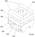
- FIG. 3a to 5 A further embodiment of the present invention is illustrated in Figures 3a to 5 .
- base support/retaining element 300 is located in the base of a container such as that illustrated in Figure 2 .
- the base retaining element 300 is formed from a substantially rectangular sheet of combustible material, e.g. cardboard, by cutting and folding.
- the sheet is aptly around 97mm wide and around 177mm long.
- a first fold line 302 is created proximal a first end region of the sheet (e.g. around 40mm from the first end of the sheet) and a second fold line 304 is created proximal a second end region of the sheet (e.g. around 40mm from the second end of the sheet).
- Four laterally spaced apart cuts 306,308,310,312 are made across each fold line. The cuts are around 30mm long.
- the innermost cuts 308,310 are spaced apart by around 37mm.
- the outermost cuts 306,312 are spaced from the outer edge of the sheet by around 10mm.
- the folds allow each end region to be folded upwardly to form two vertical end portions 314,316 oriented substantially perpendicularly to a substantially flat and horizontal base portion 318.
- the cuts across each fold line allow retaining portions 320,322,324 to be formed by folding inwardly, and two spaces are formed between the retaining portions which are sized to receive and retain a wooden fuel element.
- the spaces are around 20mm wide.
- the spaces on the first fold line are aligned with the spaces on the second fold line such that the wooden fuel elements located therein are substantially parallel with each other and the corresponding side walls of the container.
- Each retaining portion 320,322,324 provides a vertical oriented surface 330 and a horizontally oriented surface 332.
- the base retaining element 300 is slidably located into the base of the box-like container such that the base portion 304 engages with the flat base of the container and vertical end portions 314,316 engage against the respective inner faces of the sides of the container.
- a first pair of wooden fuel elements 340 is then located in the spaces provided between the retaining portions 320,322,324 of the base retaining element 300. Each space is sized such that the wooden fuel element is retained therein with no or minimal movement with respect to the base retaining element 300.
- the first pair of wooden fuel elements 340 form a first layer of a stack of combustible fuel elements and are securely located in the base retaining element 300 to ensure their position and orientation in the container is substantially fixed during assembly, storage, transportation or end use.
- the first pair of wooden elements 340 are spaced from the side wall of the container comprising the window or in which a window is formed by the user to thereby allow a match or taper to be inserted into the interior of the container to light the flammable fuel element, as described further below.
- a second pair of spaced apart wooden fuel elements 350 is then located on the first pair of wooden fuel elements 340 such that the second pair of fuel elements 350 is oriented substantially perpendicularly to the first pair of fuel elements 340.
- Each second fuel element 350 is located against a respective one of the end portions 314,316 of the base retaining element 300 and optionally on the horizontal surface 332 of the retaining portions 320,322,324 if the height of the first wooden fuel elements 340 is less than or equal to a height of the retaining portions.
- an intermediate retaining element 400 is then located on the second layer of spaced apart wooden fuel elements 350.
- the intermediate retaining member 400 is formed from a sheet of combustible material, e.g. cardboard, by creating four spaced apart fold lines 402,404,406,408 therein. A three-sided cut is made in the sheet extending outwardly from each of the inner fold lines and across each respective outer fold line to allow a pair of retaining portions 410,412 to be created.
- the retaining portions 410,412 extend outwardly in opposed directions from a substantially flat base portion 414 of the intermediate retaining element 400.
- Wing portions 416,418 are formed by folding along the inner and outer fold lines to thereby form a channel with apertures in where the retaining members were formed by cutting. The apertures allow air and combustion gases to flow up through the assembled stack from the base of the container to promote efficient burning.
- Each elongate retaining portion 410,412 includes an end region formed by folding the retaining portion along the outer fold line 402,408. Each end region is angled, e.g. perpendicularly, with respect to the remainder of the retaining portion.
- the upper portions 420 of each wing portion 416,418 are substantially parallel with the base portion 414 and the inner surfaces 422 of each wing portion 416,418 are substantially angled to define a tapered channel.
- a length of the base portion 414 is less than a length of the upper surfaces of each wing portion.
- the intermediate retaining element 300 is located on the second layer of spaced apart wooden fuel elements 350 such that the base portion 414 sits on the first pair of wooden fuel elements 340 and the upper portion 420 of each wing 416,418 sits on a respective one of the second pair of wooden fuel elements.
- the outer surface of the end region of each retaining portion 410,412 engages with the inner surface of a respective one of the second pair of wooden fuel elements 450 to urge/retain the same against the side walls of the container and to eliminate/minimise any movement of these fuel elements during assembly, storage, transportation or end use.
- an elongate flammable ignition element 450 such as a Hexamine-based firelighter or a roll of wax-bound softwood strands or the like, is located in the channel defined by the intermediate retaining element 300.
- the ends of the ignition element 450 extend beyond the base of the channel and the intermediate retaining element 400 locates the ignition element above the window provided or formed in the base of the container. This arrangement aptly allows a flame inserted through the window of the container to efficiently light the ignition element.
- Locating the ignition element above the first layer of wooden fuel elements 340 also forces air to be drawn into the container from the window/s below and creates an efficient 'top-down' method of combustion, particularly when the thinner intermediate retaining element 400 is burning and its integrity compromised such that the ignition element, if still burning, drops onto the first layer of fuel elements 340 below.
- third and fourth layers 460,462 of spaced apart wooden fuel elements are located on the fuel elements of the second layer such that the fuel elements in adjacent layers are oriented perpendicularly to each other to form a Jenga TM -style stack.
- a further pair of spaced apart wooden fuel elements 464 is located on the fourth layer to form a fifth layer of the stack.
- the fifth layer is oriented perpendicularly to the fourth layer and each of the pair of further fuel elements 464 is located against the respective wall of the container.
- An upper retaining element 500 is then located centrally into the upper portion of the stack to retain each fuel element in each of the third, fourth and fifth layers in its desired position and orientation to thereby eliminate/minimise any movement of these fuel elements during assembly, storage, transportation or end use.
- the upper retaining element 500 includes a substantially square upper portion 502 and a plurality of elongate legs portions 504 extending downwardly from each corner of the upper portion 502.
- Each leg portion 504 defines a corner of the retaining element such that it provides two retaining surfaces orientated substantially perpendicularly to each other for engaging with respective surfaces of the fuel elements.
- the upper portion 502 includes a central aperture 506 which acts as a chimney allows air to flow upwardly through the stack and to guide combustion gases, e.g. smoke, from the burning stack towards an opening in the top of the container.
- the upper retaining element 500 is formed from a sheet of combustible material, e.g. cardboard, and each side portion thereof is folded downwardly to be perpendicular to the upper portion to thereby form each of the corner leg portions.
- the two sides of each leg portion may be connected together, e.g.
- the square upper portion 502 is around 56x56mm and each side portion is around 50mm long. The sides of each leg portion are around 17mm wide and the space between adjacent leg portions is around 22mm.
- the aperture 506 in the upper portion 502 is around 32mm in diameter.
- the space or gap between the leg portions does not extend to the upper portion to thereby locate the flat upper surface of the upper retaining member 500 on or proximal the plane defined by the upper layer of fuel elements 464. This ensures the movement of the upper retaining member 500 in an axial direction of the stack is limited, particularly during storage and transit if, for example, the container is inverted. In this situation, axial movement of the upper retaining member with respect to the stack would be limited by the lid of the container to ensure the fuel elements in the third, fourth and fifth layers remain retained in their desired position and orientation.
- a suitable container to contain the stack illustrated in Figures 3a to 5 is identical or similar to the container illustrated in Figure 2 .
- the container is substantially box-like having six sides of equal dimensions and a closable lid.
- the inner dimensions of the container are substantially the same as the outer limits of the assembled stack to thereby ensure, in combination with the retaining elements, the stack does not collapse/move around in the container during assembly, storage, transit, and use.
- An opening is aptly pre-provided or creatable by a user in the lower portion of the container wall such that the opening is directly under an end region of the flammable ignition element 450.
- the opening may or may not extend into the base of the container.
- the container may be configured to provide an opening for igniting either or both end regions of the flammable ignition element, i.e. an opening may be pre-provided or creatable by a user in either or both opposed sides of the container. Providing an opening in the lower portion of both opposed sides of the container allows the ignition element to be lit at one or both ends and also allows additional air to be drawn into the bottom of the stack from both opposed sides.
- Certain embodiments of the present invention therefore provide apparatus for quickly and safely starting a fire in an efficient and consistent manner.
- the apparatus is preassembled which eliminates the need for a user to build a suitable fire or have any knowledge of building a suitable fire.
- the apparatus is contained which ensures the fuel elements remain in a stack for as long as possible to maximise ignition and combustion efficiency thereof.
- the apparatus is assembled in a manner which promotes efficient ignition and combustion of the stack of fuel elements thereof.
- the apparatus ensures a clean start with minimum smoke and soot to thereby be environmentally friendly.
- the apparatus eliminates the need for large amounts of newspaper to be used as is the case with conventional fire lighting methods which is undesirably a significant source of non-combustible ash.
- the apparatus is contained and the elements thereof are retained in a desired position and orientation to eliminate/minimise any movement of these fuel elements during assembly, storage, transportation or end use.
- the size and shape of the assembled apparatus also allows for efficient transit and storage.
Landscapes
- Chemical & Material Sciences (AREA)
- Engineering & Computer Science (AREA)
- Organic Chemistry (AREA)
- Oil, Petroleum & Natural Gas (AREA)
- Manufacturing & Machinery (AREA)
- Combustion & Propulsion (AREA)
- Mechanical Engineering (AREA)
- Wood Science & Technology (AREA)
- Life Sciences & Earth Sciences (AREA)
- Biodiversity & Conservation Biology (AREA)
- Ecology (AREA)
- Forests & Forestry (AREA)
- General Engineering & Computer Science (AREA)
- Food Science & Technology (AREA)
- Solid-Fuel Combustion (AREA)
- Solid Fuels And Fuel-Associated Substances (AREA)
- Cookers (AREA)
Claims (15)
- Appareil pour amorcer un feu, comprenant :un empilement d'éléments combustibles et un élément d'allumage inflammable placés dans un récipient à combustible conçu pour fournir au moins une ouverture pour l'allumage de l'élément d'allumage inflammable placé dans celui-ci ;dans lequel l'élément d'allumage est supporté par au moins deux des éléments combustibles et l'au moins une ouverture est située sous l'élément d'allumage.
- Appareil selon la revendication 1, dans lequel l'élément d'allumage est placé sur un élément de retenue intermédiaire au-dessus d'une première paire des éléments combustibles mutuellement espacés, placés au niveau d'une région de base du récipient.
- Appareil selon la revendication 2, dans lequel la première paire d'éléments combustibles mutuellement espacés sont placés dans un élément de retenue de base disposé sur la région de base du récipient.
- Appareil selon la revendication 2 ou 3, dans lequel l'élément de retenue intermédiaire est supporté entre une deuxième paire des éléments combustibles mutuellement espacés, placés sur la première paire d'éléments combustibles et orientés perpendiculairement à ceux-ci.
- Appareil selon la revendication 4, dans lequel l'élément de retenue intermédiaire définit un canal pour le placement de l'élément d'allumage entre la deuxième paire d'éléments combustibles mutuellement espacés.
- Appareil selon la revendication 5, dans lequel l'élément de retenue intermédiaire comprend une partie base et une paire de parties de retenue allongées s'étendant vers l'extérieur dans des directions opposées à partir de celle-ci destinées à venir en prise avec un élément respectif parmi les deuxièmes éléments combustibles et à le retenir dans une position et une orientation prédéterminées à l'intérieur du récipient.
- Appareil selon la revendication 6, dans lequel d'autres éléments combustibles sont placés sur la deuxième couche afin de former d'autres couches de l'empilement, les éléments combustibles de chaque couche étant mutuellement espacés et orientés de manière essentiellement perpendiculaire par rapport aux éléments combustibles des couches adjacentes.
- Appareil selon la revendication 7, comprenant au moins un autre élément de retenue pour empêcher au moins les éléments combustibles des autres couches de bouger sensiblement les uns par rapport aux autres et par rapport au récipient.
- Appareil selon la revendication 8, dans lequel l'au moins un autre élément de retenue comprend une pluralité de parties de retenue orientées verticalement placées entre les éléments combustibles mutuellement espacés des autres couches, et dans lequel l'au moins un autre élément de retenue comprend éventuellement une partie supérieure à partir de laquelle chaque partie de retenue s'étend et comportant dans celle-ci au moins une ouverture.
- Procédé d'assemblage d'un appareil pour amorcer un feu, comprenant :le placement d'un empilement d'éléments combustibles et d'un élément d'allumage inflammable dans un récipient à combustible conçu pour fournir au moins une ouverture pour l'allumage de l'élément d'allumage inflammable placé dans celui-ci ;dans lequel l'élément d'allumage est supporté par au moins deux des éléments combustibles et l'au moins une ouverture est située sous l'élément d'allumage.
- Procédé selon la revendication 10, dans lequel les éléments combustibles de support sont mutuellement espacés et placés de chaque côté de l'au moins une ouverture ou d'une partie ouvrable du récipient conçue pour fournir de manière sélective l'au moins une ouverture.
- Procédé selon la revendication 11, comprenant le placement de l'élément d'allumage sur un élément de retenue intermédiaire au-dessus d'une première paire des éléments combustibles mutuellement espacés, placés sur une base du récipient.
- Procédé selon la revendication 12, comprenant la mise en appui de l'élément de retenue intermédiaire entre une deuxième paire des éléments combustibles mutuellement espacés, placés sur la première paire d'éléments combustibles et orientés perpendiculairement à ceux-ci.
- Procédé selon la revendication 13, comprenant le placement d'autres couches desdits éléments combustibles sur la deuxième couche, les éléments combustibles de chaque autre couche étant mutuellement espacés et orientés de manière essentiellement perpendiculaire par rapport aux éléments combustibles des couches adjacentes.
- Procédé selon la revendication 14, comprenant le placement d'au moins un autre élément de retenue dans l'empilement pour empêcher au moins les éléments combustibles des autres couches de bouger sensiblement les uns par rapport aux autres et par rapport au récipient.
Priority Applications (1)
| Application Number | Priority Date | Filing Date | Title |
|---|---|---|---|
| PL19705789T PL3814459T3 (pl) | 2018-06-27 | 2019-02-06 | Rozpałka |
Applications Claiming Priority (3)
| Application Number | Priority Date | Filing Date | Title |
|---|---|---|---|
| GBGB1810504.9A GB201810504D0 (en) | 2018-06-27 | 2018-06-27 | A fire starter |
| GBGB1812511.2A GB201812511D0 (en) | 2018-07-31 | 2018-07-31 | A fire starter |
| PCT/GB2019/050311 WO2020002867A1 (fr) | 2018-06-27 | 2019-02-06 | Allume-feu |
Publications (2)
| Publication Number | Publication Date |
|---|---|
| EP3814459A1 EP3814459A1 (fr) | 2021-05-05 |
| EP3814459B1 true EP3814459B1 (fr) | 2022-01-26 |
Family
ID=65444278
Family Applications (1)
| Application Number | Title | Priority Date | Filing Date |
|---|---|---|---|
| EP19705789.6A Active EP3814459B1 (fr) | 2018-06-27 | 2019-02-06 | Allume-feu |
Country Status (8)
| Country | Link |
|---|---|
| US (2) | US11480336B2 (fr) |
| EP (1) | EP3814459B1 (fr) |
| JP (1) | JP7055489B2 (fr) |
| DK (1) | DK3814459T3 (fr) |
| ES (1) | ES2908478T3 (fr) |
| GB (2) | GB2575139B (fr) |
| PL (1) | PL3814459T3 (fr) |
| WO (1) | WO2020002867A1 (fr) |
Families Citing this family (3)
| Publication number | Priority date | Publication date | Assignee | Title |
|---|---|---|---|---|
| GB2575139B (en) | 2018-06-27 | 2020-10-07 | Hot Box Stoves Ltd | A fire starter |
| RU2766501C1 (ru) * | 2021-09-02 | 2022-03-15 | Михаил Владимирович Корецкий | Одноразовое приспособление для разжигания угля в мангале |
| IT202300024783A1 (it) * | 2023-11-22 | 2025-05-22 | Ivo GIULIANELLI | Dispositivo accendifuoco |
Family Cites Families (16)
| Publication number | Priority date | Publication date | Assignee | Title |
|---|---|---|---|---|
| GB130923A (en) * | 1919-03-11 | 1919-08-14 | Richard Powell | A New or Improved Firelighter. |
| GB887048A (en) * | 1958-11-18 | 1962-01-17 | Leslie William Bryant | A combustible product |
| US4063904A (en) * | 1975-11-18 | 1977-12-20 | Beeson Frank C | Self-contained fire package |
| US4627854A (en) * | 1985-11-04 | 1986-12-09 | Firebox Corporation | Self-contained log fire starting kit |
| US4906254A (en) * | 1987-04-23 | 1990-03-06 | Antosko Henry B | Fuel package |
| US4762525A (en) * | 1987-06-15 | 1988-08-09 | Wood William P | Prepackaged firebox apparatus for outdoor cooking or the like |
| IE892711A1 (en) * | 1989-08-23 | 1991-08-14 | Lorenzo Macciocca | A packaged combustible |
| WO2003099968A2 (fr) * | 2002-05-22 | 2003-12-04 | Henry Michael Taylor | Appareil allume-feu portatif |
| GB2442702A (en) * | 2006-10-09 | 2008-04-16 | Annie Chang | Carbon fuel combustion package |
| US20150191669A1 (en) * | 2014-01-07 | 2015-07-09 | Jorge Alberto Preciat Cervera | Fire Starting Device and Method of Use |
| CA2852290C (fr) * | 2014-05-23 | 2020-10-20 | Sean P. A. Price | Quick fire cube |
| CA2871765A1 (fr) * | 2014-11-21 | 2016-05-21 | Philip E. Kennedy | Foyer pret-a-l'emploi |
| US20170002284A1 (en) * | 2015-06-30 | 2017-01-05 | Sean Price | Fire cube |
| KR101694078B1 (ko) * | 2015-11-24 | 2017-01-06 | 김재명 | 숯 연료 포장체 |
| US20170253823A1 (en) * | 2016-03-03 | 2017-09-07 | Stanley Jones | Combustible Fire Starting Kit |
| GB2575139B (en) | 2018-06-27 | 2020-10-07 | Hot Box Stoves Ltd | A fire starter |
-
2019
- 2019-02-06 GB GB1901607.0A patent/GB2575139B/en active Active
- 2019-02-06 DK DK19705789.6T patent/DK3814459T3/da active
- 2019-02-06 GB GB2011402.1A patent/GB2592284B/en active Active
- 2019-02-06 WO PCT/GB2019/050311 patent/WO2020002867A1/fr not_active Ceased
- 2019-02-06 PL PL19705789T patent/PL3814459T3/pl unknown
- 2019-02-06 ES ES19705789T patent/ES2908478T3/es active Active
- 2019-02-06 US US17/253,377 patent/US11480336B2/en active Active
- 2019-02-06 JP JP2020569135A patent/JP7055489B2/ja active Active
- 2019-02-06 EP EP19705789.6A patent/EP3814459B1/fr active Active
-
2022
- 2022-10-06 US US17/961,340 patent/US12031722B2/en active Active
Also Published As
| Publication number | Publication date |
|---|---|
| JP2021525824A (ja) | 2021-09-27 |
| GB201901607D0 (en) | 2019-03-27 |
| GB2575139A (en) | 2020-01-01 |
| GB202011402D0 (en) | 2020-09-09 |
| CA3103063A1 (fr) | 2020-01-02 |
| US20210262664A1 (en) | 2021-08-26 |
| US20230021532A1 (en) | 2023-01-26 |
| ES2908478T3 (es) | 2022-04-29 |
| WO2020002867A1 (fr) | 2020-01-02 |
| JP7055489B2 (ja) | 2022-04-18 |
| GB2592284A (en) | 2021-08-25 |
| PL3814459T3 (pl) | 2022-03-28 |
| US11480336B2 (en) | 2022-10-25 |
| GB2592284B (en) | 2021-11-17 |
| US12031722B2 (en) | 2024-07-09 |
| DK3814459T3 (da) | 2022-03-14 |
| GB2575139B (en) | 2020-10-07 |
| EP3814459A1 (fr) | 2021-05-05 |
Similar Documents
| Publication | Publication Date | Title |
|---|---|---|
| US12031722B2 (en) | Fire starter | |
| US4762525A (en) | Prepackaged firebox apparatus for outdoor cooking or the like | |
| US20090095276A1 (en) | Apparatus, Systems and Methods For Facilitating Ignition Of A Solid Fuel | |
| EP2638324B1 (fr) | Structure d'Allumage Combustible | |
| US3367757A (en) | Fire kindling device | |
| US20150315508A1 (en) | Disposable chimney charcoal starter, fuel package and method for starting a fire | |
| US20150047626A1 (en) | Charcoal starter with a consumable fire ignition method and system | |
| US8216322B2 (en) | Solid fuel fire starter | |
| US20190315510A1 (en) | Fire-starter and method thereof having improved ventilation | |
| US20170002284A1 (en) | Fire cube | |
| US10602880B2 (en) | Fuel-containing fire-starting device | |
| CA3103063C (fr) | Allume-feu | |
| US10098503B2 (en) | Solventless fire ignition systems and methods thereof | |
| WO2017165905A1 (fr) | Configuration de démarrage d'incendie et procédé associé | |
| US20210022550A1 (en) | Fire starter tube | |
| JP6555596B2 (ja) | 燃焼用木材及び燃焼用木材と着火材とのセット並びに燃焼用木材と被覆金属片とのセット、燃焼用木材の燃焼方法 | |
| EP2925837B1 (fr) | Bois d'allumage pour allumer un feu | |
| CA2852290C (fr) | Quick fire cube | |
| FI121116B (fi) | Sytytin | |
| US11643611B2 (en) | Fire starting strip | |
| RU110629U1 (ru) | Емкость для розжига топливных брикетов (варианты) | |
| DE202010010617U1 (de) | Anzünder | |
| DE202020000522U1 (de) | Einweggerät zum Zünden fester Brennstoffe in Form eines brennbaren Behälters zum Aufbewahren, Abstellen und Zünden, hauptsächlich von Holzkohle | |
| WO2018138483A1 (fr) | Réchaud de camping compact à combustible solide | |
| HK1156066A (en) | Environmentally safe charcoal-based heat source |
Legal Events
| Date | Code | Title | Description |
|---|---|---|---|
| STAA | Information on the status of an ep patent application or granted ep patent |
Free format text: STATUS: UNKNOWN |
|
| STAA | Information on the status of an ep patent application or granted ep patent |
Free format text: STATUS: THE INTERNATIONAL PUBLICATION HAS BEEN MADE |
|
| PUAI | Public reference made under article 153(3) epc to a published international application that has entered the european phase |
Free format text: ORIGINAL CODE: 0009012 |
|
| STAA | Information on the status of an ep patent application or granted ep patent |
Free format text: STATUS: REQUEST FOR EXAMINATION WAS MADE |
|
| 17P | Request for examination filed |
Effective date: 20210113 |
|
| AK | Designated contracting states |
Kind code of ref document: A1 Designated state(s): AL AT BE BG CH CY CZ DE DK EE ES FI FR GB GR HR HU IE IS IT LI LT LU LV MC MK MT NL NO PL PT RO RS SE SI SK SM TR |
|
| DAV | Request for validation of the european patent (deleted) | ||
| DAX | Request for extension of the european patent (deleted) | ||
| GRAP | Despatch of communication of intention to grant a patent |
Free format text: ORIGINAL CODE: EPIDOSNIGR1 |
|
| STAA | Information on the status of an ep patent application or granted ep patent |
Free format text: STATUS: GRANT OF PATENT IS INTENDED |
|
| RIC1 | Information provided on ipc code assigned before grant |
Ipc: B65D 5/50 20060101ALI20211005BHEP Ipc: C10L 11/04 20060101ALI20211005BHEP Ipc: B65D 5/42 20060101ALI20211005BHEP Ipc: A47J 37/07 20060101ALI20211005BHEP Ipc: C10L 11/06 20060101AFI20211005BHEP |
|
| INTG | Intention to grant announced |
Effective date: 20211102 |
|
| GRAS | Grant fee paid |
Free format text: ORIGINAL CODE: EPIDOSNIGR3 |
|
| GRAA | (expected) grant |
Free format text: ORIGINAL CODE: 0009210 |
|
| STAA | Information on the status of an ep patent application or granted ep patent |
Free format text: STATUS: THE PATENT HAS BEEN GRANTED |
|
| AK | Designated contracting states |
Kind code of ref document: B1 Designated state(s): AL AT BE BG CH CY CZ DE DK EE ES FI FR GB GR HR HU IE IS IT LI LT LU LV MC MK MT NL NO PL PT RO RS SE SI SK SM TR |
|
| REG | Reference to a national code |
Ref country code: GB Ref legal event code: FG4D |
|
| REG | Reference to a national code |
Ref country code: CH Ref legal event code: EP |
|
| REG | Reference to a national code |
Ref country code: AT Ref legal event code: REF Ref document number: 1465313 Country of ref document: AT Kind code of ref document: T Effective date: 20220215 |
|
| REG | Reference to a national code |
Ref country code: IE Ref legal event code: FG4D |
|
| REG | Reference to a national code |
Ref country code: DE Ref legal event code: R096 Ref document number: 602019011243 Country of ref document: DE |
|
| REG | Reference to a national code |
Ref country code: FI Ref legal event code: FGE |
|
| REG | Reference to a national code |
Ref country code: DK Ref legal event code: T3 Effective date: 20220310 |
|
| REG | Reference to a national code |
Ref country code: NO Ref legal event code: T2 Effective date: 20220126 |
|
| REG | Reference to a national code |
Ref country code: SE Ref legal event code: TRGR |
|
| REG | Reference to a national code |
Ref country code: NL Ref legal event code: FP |
|
| REG | Reference to a national code |
Ref country code: ES Ref legal event code: FG2A Ref document number: 2908478 Country of ref document: ES Kind code of ref document: T3 Effective date: 20220429 |
|
| REG | Reference to a national code |
Ref country code: LT Ref legal event code: MG9D |
|
| PG25 | Lapsed in a contracting state [announced via postgrant information from national office to epo] |
Ref country code: RS Free format text: LAPSE BECAUSE OF FAILURE TO SUBMIT A TRANSLATION OF THE DESCRIPTION OR TO PAY THE FEE WITHIN THE PRESCRIBED TIME-LIMIT Effective date: 20220126 Ref country code: PT Free format text: LAPSE BECAUSE OF FAILURE TO SUBMIT A TRANSLATION OF THE DESCRIPTION OR TO PAY THE FEE WITHIN THE PRESCRIBED TIME-LIMIT Effective date: 20220526 Ref country code: LT Free format text: LAPSE BECAUSE OF FAILURE TO SUBMIT A TRANSLATION OF THE DESCRIPTION OR TO PAY THE FEE WITHIN THE PRESCRIBED TIME-LIMIT Effective date: 20220126 Ref country code: HR Free format text: LAPSE BECAUSE OF FAILURE TO SUBMIT A TRANSLATION OF THE DESCRIPTION OR TO PAY THE FEE WITHIN THE PRESCRIBED TIME-LIMIT Effective date: 20220126 Ref country code: BG Free format text: LAPSE BECAUSE OF FAILURE TO SUBMIT A TRANSLATION OF THE DESCRIPTION OR TO PAY THE FEE WITHIN THE PRESCRIBED TIME-LIMIT Effective date: 20220426 |
|
| PG25 | Lapsed in a contracting state [announced via postgrant information from national office to epo] |
Ref country code: LV Free format text: LAPSE BECAUSE OF FAILURE TO SUBMIT A TRANSLATION OF THE DESCRIPTION OR TO PAY THE FEE WITHIN THE PRESCRIBED TIME-LIMIT Effective date: 20220126 Ref country code: GR Free format text: LAPSE BECAUSE OF FAILURE TO SUBMIT A TRANSLATION OF THE DESCRIPTION OR TO PAY THE FEE WITHIN THE PRESCRIBED TIME-LIMIT Effective date: 20220427 |
|
| PG25 | Lapsed in a contracting state [announced via postgrant information from national office to epo] |
Ref country code: IS Free format text: LAPSE BECAUSE OF FAILURE TO SUBMIT A TRANSLATION OF THE DESCRIPTION OR TO PAY THE FEE WITHIN THE PRESCRIBED TIME-LIMIT Effective date: 20220526 |
|
| REG | Reference to a national code |
Ref country code: CH Ref legal event code: PL |
|
| REG | Reference to a national code |
Ref country code: DE Ref legal event code: R097 Ref document number: 602019011243 Country of ref document: DE |
|
| PG25 | Lapsed in a contracting state [announced via postgrant information from national office to epo] |
Ref country code: SM Free format text: LAPSE BECAUSE OF FAILURE TO SUBMIT A TRANSLATION OF THE DESCRIPTION OR TO PAY THE FEE WITHIN THE PRESCRIBED TIME-LIMIT Effective date: 20220126 Ref country code: SK Free format text: LAPSE BECAUSE OF FAILURE TO SUBMIT A TRANSLATION OF THE DESCRIPTION OR TO PAY THE FEE WITHIN THE PRESCRIBED TIME-LIMIT Effective date: 20220126 Ref country code: RO Free format text: LAPSE BECAUSE OF FAILURE TO SUBMIT A TRANSLATION OF THE DESCRIPTION OR TO PAY THE FEE WITHIN THE PRESCRIBED TIME-LIMIT Effective date: 20220126 Ref country code: MC Free format text: LAPSE BECAUSE OF FAILURE TO SUBMIT A TRANSLATION OF THE DESCRIPTION OR TO PAY THE FEE WITHIN THE PRESCRIBED TIME-LIMIT Effective date: 20220126 Ref country code: LU Free format text: LAPSE BECAUSE OF NON-PAYMENT OF DUE FEES Effective date: 20220206 Ref country code: EE Free format text: LAPSE BECAUSE OF FAILURE TO SUBMIT A TRANSLATION OF THE DESCRIPTION OR TO PAY THE FEE WITHIN THE PRESCRIBED TIME-LIMIT Effective date: 20220126 Ref country code: CZ Free format text: LAPSE BECAUSE OF FAILURE TO SUBMIT A TRANSLATION OF THE DESCRIPTION OR TO PAY THE FEE WITHIN THE PRESCRIBED TIME-LIMIT Effective date: 20220126 |
|
| PG25 | Lapsed in a contracting state [announced via postgrant information from national office to epo] |
Ref country code: AL Free format text: LAPSE BECAUSE OF FAILURE TO SUBMIT A TRANSLATION OF THE DESCRIPTION OR TO PAY THE FEE WITHIN THE PRESCRIBED TIME-LIMIT Effective date: 20220126 |
|
| PLBE | No opposition filed within time limit |
Free format text: ORIGINAL CODE: 0009261 |
|
| STAA | Information on the status of an ep patent application or granted ep patent |
Free format text: STATUS: NO OPPOSITION FILED WITHIN TIME LIMIT |
|
| 26N | No opposition filed |
Effective date: 20221027 |
|
| PG25 | Lapsed in a contracting state [announced via postgrant information from national office to epo] |
Ref country code: LI Free format text: LAPSE BECAUSE OF NON-PAYMENT OF DUE FEES Effective date: 20220228 Ref country code: CH Free format text: LAPSE BECAUSE OF NON-PAYMENT OF DUE FEES Effective date: 20220228 |
|
| P01 | Opt-out of the competence of the unified patent court (upc) registered |
Effective date: 20230509 |
|
| REG | Reference to a national code |
Ref country code: AT Ref legal event code: UEP Ref document number: 1465313 Country of ref document: AT Kind code of ref document: T Effective date: 20220126 |
|
| PG25 | Lapsed in a contracting state [announced via postgrant information from national office to epo] |
Ref country code: MK Free format text: LAPSE BECAUSE OF FAILURE TO SUBMIT A TRANSLATION OF THE DESCRIPTION OR TO PAY THE FEE WITHIN THE PRESCRIBED TIME-LIMIT Effective date: 20220126 Ref country code: CY Free format text: LAPSE BECAUSE OF FAILURE TO SUBMIT A TRANSLATION OF THE DESCRIPTION OR TO PAY THE FEE WITHIN THE PRESCRIBED TIME-LIMIT Effective date: 20220126 |
|
| PG25 | Lapsed in a contracting state [announced via postgrant information from national office to epo] |
Ref country code: HU Free format text: LAPSE BECAUSE OF FAILURE TO SUBMIT A TRANSLATION OF THE DESCRIPTION OR TO PAY THE FEE WITHIN THE PRESCRIBED TIME-LIMIT; INVALID AB INITIO Effective date: 20190206 |
|
| PG25 | Lapsed in a contracting state [announced via postgrant information from national office to epo] |
Ref country code: MT Free format text: LAPSE BECAUSE OF FAILURE TO SUBMIT A TRANSLATION OF THE DESCRIPTION OR TO PAY THE FEE WITHIN THE PRESCRIBED TIME-LIMIT Effective date: 20220126 |
|
| PG25 | Lapsed in a contracting state [announced via postgrant information from national office to epo] |
Ref country code: TR Free format text: LAPSE BECAUSE OF FAILURE TO SUBMIT A TRANSLATION OF THE DESCRIPTION OR TO PAY THE FEE WITHIN THE PRESCRIBED TIME-LIMIT Effective date: 20220126 |
|
| PG25 | Lapsed in a contracting state [announced via postgrant information from national office to epo] |
Ref country code: SI Free format text: LAPSE BECAUSE OF FAILURE TO SUBMIT A TRANSLATION OF THE DESCRIPTION OR TO PAY THE FEE WITHIN THE PRESCRIBED TIME-LIMIT Effective date: 20220126 |
|
| PGFP | Annual fee paid to national office [announced via postgrant information from national office to epo] |
Ref country code: NL Payment date: 20260119 Year of fee payment: 8 |
|
| PGFP | Annual fee paid to national office [announced via postgrant information from national office to epo] |
Ref country code: SE Payment date: 20260119 Year of fee payment: 8 |
|
| PGFP | Annual fee paid to national office [announced via postgrant information from national office to epo] |
Ref country code: GB Payment date: 20260209 Year of fee payment: 8 |
|
| PGFP | Annual fee paid to national office [announced via postgrant information from national office to epo] |
Ref country code: ES Payment date: 20260306 Year of fee payment: 8 |
|
| PGFP | Annual fee paid to national office [announced via postgrant information from national office to epo] |
Ref country code: NO Payment date: 20260126 Year of fee payment: 8 Ref country code: DK Payment date: 20260122 Year of fee payment: 8 Ref country code: DE Payment date: 20260114 Year of fee payment: 8 Ref country code: IE Payment date: 20260209 Year of fee payment: 8 |
|
| PGFP | Annual fee paid to national office [announced via postgrant information from national office to epo] |
Ref country code: AT Payment date: 20260109 Year of fee payment: 8 |
|
| PGFP | Annual fee paid to national office [announced via postgrant information from national office to epo] |
Ref country code: FI Payment date: 20260109 Year of fee payment: 8 Ref country code: BE Payment date: 20260114 Year of fee payment: 8 Ref country code: IT Payment date: 20260109 Year of fee payment: 8 |
|
| PGFP | Annual fee paid to national office [announced via postgrant information from national office to epo] |
Ref country code: FR Payment date: 20260128 Year of fee payment: 8 |
|
| PGFP | Annual fee paid to national office [announced via postgrant information from national office to epo] |
Ref country code: PL Payment date: 20260108 Year of fee payment: 8 |