EP3814567B1 - Appareil d'entretien de vêtements - Google Patents
Appareil d'entretien de vêtements Download PDFInfo
- Publication number
- EP3814567B1 EP3814567B1 EP19858781.8A EP19858781A EP3814567B1 EP 3814567 B1 EP3814567 B1 EP 3814567B1 EP 19858781 A EP19858781 A EP 19858781A EP 3814567 B1 EP3814567 B1 EP 3814567B1
- Authority
- EP
- European Patent Office
- Prior art keywords
- condensed water
- duct
- clothes care
- steam
- clothes
- Prior art date
- Legal status (The legal status is an assumption and is not a legal conclusion. Google has not performed a legal analysis and makes no representation as to the accuracy of the status listed.)
- Active
Links
Images


Classifications
-
- D—TEXTILES; PAPER
- D06—TREATMENT OF TEXTILES OR THE LIKE; LAUNDERING; FLEXIBLE MATERIALS NOT OTHERWISE PROVIDED FOR
- D06F—LAUNDERING, DRYING, IRONING, PRESSING OR FOLDING TEXTILE ARTICLES
- D06F73/00—Apparatus for smoothing or removing creases from garments or other textile articles by formers, cores, stretchers, or internal frames, with the application of heat or steam
- D06F73/02—Apparatus for smoothing or removing creases from garments or other textile articles by formers, cores, stretchers, or internal frames, with the application of heat or steam having one or more treatment chambers
-
- D—TEXTILES; PAPER
- D06—TREATMENT OF TEXTILES OR THE LIKE; LAUNDERING; FLEXIBLE MATERIALS NOT OTHERWISE PROVIDED FOR
- D06F—LAUNDERING, DRYING, IRONING, PRESSING OR FOLDING TEXTILE ARTICLES
- D06F58/00—Domestic laundry dryers
- D06F58/20—General details of domestic laundry dryers
- D06F58/24—Condensing arrangements
-
- D—TEXTILES; PAPER
- D06—TREATMENT OF TEXTILES OR THE LIKE; LAUNDERING; FLEXIBLE MATERIALS NOT OTHERWISE PROVIDED FOR
- D06F—LAUNDERING, DRYING, IRONING, PRESSING OR FOLDING TEXTILE ARTICLES
- D06F58/00—Domestic laundry dryers
- D06F58/20—General details of domestic laundry dryers
- D06F58/203—Laundry conditioning arrangements
-
- D—TEXTILES; PAPER
- D06—TREATMENT OF TEXTILES OR THE LIKE; LAUNDERING; FLEXIBLE MATERIALS NOT OTHERWISE PROVIDED FOR
- D06F—LAUNDERING, DRYING, IRONING, PRESSING OR FOLDING TEXTILE ARTICLES
- D06F35/00—Washing machines, apparatus, or methods not otherwise provided for
-
- D—TEXTILES; PAPER
- D06—TREATMENT OF TEXTILES OR THE LIKE; LAUNDERING; FLEXIBLE MATERIALS NOT OTHERWISE PROVIDED FOR
- D06F—LAUNDERING, DRYING, IRONING, PRESSING OR FOLDING TEXTILE ARTICLES
- D06F39/00—Details of washing machines not specific to a single type of machines covered by groups D06F9/00 - D06F27/00
- D06F39/08—Liquid supply or discharge arrangements
- D06F39/083—Liquid discharge or recirculation arrangements
-
- D—TEXTILES; PAPER
- D06—TREATMENT OF TEXTILES OR THE LIKE; LAUNDERING; FLEXIBLE MATERIALS NOT OTHERWISE PROVIDED FOR
- D06F—LAUNDERING, DRYING, IRONING, PRESSING OR FOLDING TEXTILE ARTICLES
- D06F39/00—Details of washing machines not specific to a single type of machines covered by groups D06F9/00 - D06F27/00
- D06F39/08—Liquid supply or discharge arrangements
- D06F39/088—Liquid supply arrangements
-
- D—TEXTILES; PAPER
- D06—TREATMENT OF TEXTILES OR THE LIKE; LAUNDERING; FLEXIBLE MATERIALS NOT OTHERWISE PROVIDED FOR
- D06F—LAUNDERING, DRYING, IRONING, PRESSING OR FOLDING TEXTILE ARTICLES
- D06F58/00—Domestic laundry dryers
- D06F58/10—Drying cabinets or drying chambers having heating or ventilating means
Definitions
- the clothes care apparatus may have a clothes support member provided in the storage compartment for mounting the clothes.
- the clothes care apparatus may take care of clothes by translational and/or rotational movement of the clothes support member, or take care of the clothes by providing airflow to the clothes support member.
- US3,752,373A discloses a portable wardrobe refresher having a drainboard partition, at whose low point is centered a pipe which drains collected liquid into the steam compartment.
- the clothes care apparatus may further include a guide plate provided in the clothes care compartment below the condensed water outlet to guide the condensed water discharged from the condensed water outlet to the drain hole.
- the duct may include a communication port configured to connect the first duct to the second duct, and a connecting member to connect the first duct to the second duct to drain condensed water from the second duct, to the first duct.
- the clothes care apparatus may further include a water drain tank arranged inside the machine room and connected to the first duct to collect condensed water from the first duct.
- the guide plate may include a recessed guide groove to form a water channel configured to guide the condensed water discharged from the condensed water outlet to the machine room.
- the guide plate may include a plurality of protruding guide ribs to form a water channel configured to guide the condensed water discharged from the condensed water outlet to the machine room.
- the clothes care apparatus may further include a plate cover configured to cover a flow of the condensed water in the guide plate.
- the clothes care apparatus includes a drain hole formed to guide the condensed water, which is discharged from a steam injector to a clothes care compartment, to a duct of a machine room connected to a water drain tank, and thus it is possible to collect condensed water, which is generated by the steam injector, by using a relatively simple configuration.
- first, second, third, etc. may be used herein to describe various elements, but elements are not limited by these terms. These terms are only used to distinguish one element from another element. For example, without departing from the scope of the disclosure, a first element may be termed as a second element, and a second element may be termed as a first element.
- the term of "and / or" includes a plurality of combinations of relevant items or any one item among a plurality of relevant items.
- FIG. 1 is a view of a clothes care apparatus according to an embodiment of the disclosure.
- FIG. 2 is a view illustrating a state in which a door of the clothes care apparatus of FIG. 1 is opened.
- FIG. 3 is a side cross-sectional view of the clothes care apparatus of FIG. 1 .
- FIG. 4 is an exploded view illustrating the clothes care apparatus of FIG. 1 .
- a clothes care apparatus 1 may include a body 10 forming an external appearance, a door 20 rotatably coupled to body 10, a clothes care compartment 30 provided inside the body 10 to allow clothes to be placed and to be managed, a clothes support member 50 provided inside the clothes care compartment 30 to allow clothes to be hung thereon, and a machine room 40 provided with a heat exchanger 41 configured to dehumidify or heat air inside the clothes care compartment 30.
- the body 10 has the clothes care compartment 30 formed therein, and may have a hexahedron shape having an open one surface.
- An opening 10a may be formed on the front surface of the body 10.
- the door 20 is rotatably coupled to the opening 10a of the body 10 to open and close the clothes care compartment 30.
- the door 20 may be installed through a connecting member such as a hinge and a link.
- the body 10 may include an outer cabinet 11 and an inner cabinet 12 arranged inside the outer cabinet 11.
- the clothes care compartment 30 forms a space in which clothes are accommodated.
- the clothes care compartment 30 may include an upper surface 12a, a lower surface 12b, a left side surface 12c, a right side surface 12d, and a rear surface 12e provided in the inner cabinet 12.
- the front surface of the clothes care compartment 30 is formed to be open. Therefore, the opening of the clothes care compartment 30 may also be opened and closed by the door 20 configured to open and close the opening 10a of the body 10.
- the clothes care compartment 30 may include a first airflow inlet 31a, a second airflow inlet 32a, a first airflow outlet 31b, and a second airflow outlet 32b.
- the first airflow inlet 31a and the first airflow outlet 31b may be formed on the lower surface 12b of the clothes care compartment 30.
- the first airflow inlet 31a may be arranged in front of the lower surface 12b of the clothes care compartment 30.
- the first airflow outlet 31b may be arranged behind the lower surface 12b of the clothes care compartment 30.
- the first airflow inlet 31a and the first airflow outlet 31b may be arranged adjacent to each other.
- the second airflow inlet 32a may be formed at an upper portion of the rear surface 12e of the clothes care compartment 30.
- the second air flow outlet 32b may be formed at a substantially central portion of the upper surface 12a of the clothes care compartment 30.
- the second airflow inlet 32a and the second airflow outlet 32b may be arranged adjacent to each other.
- a water drain tank 61 and a water supply tank 71 removably installed to the body 10 may be installed in the lower portion of the body 10.
- the water drain tank 61 and the water supply tank 71 may be arranged under the clothes care compartment 30.
- the water drain tank 61 may be configured to easily treat condensed water generated in the clothes care compartment 30.
- the water drain tank 61 may collect various types of condensed water generated by the clothes care apparatus 1.
- the water drain tank 61 may be removably mounted to the body 10 so as to easily treat the collected water.
- the water supply tank 71 stores water needed for generating steam for the steam generation device 70. Water stored in the water supply tank 71 is supplied to the steam generation device 70 to form steam.
- the water supply tank 71 may be removably installed to the body 10 to easily supplement water.
- the refrigerant evaporates in the evaporator 41a of the heat exchanger 41
- the refrigerant absorbs latent heat of the ambient air so as to condense and remove moisture in the air.
- the latent heat is released toward the ambient air to heat the ambient air. That is, the evaporator 41a and the condenser 41b function as heat exchangers, and the air, which flows into the machine room 40 by the first fan 42, is dehumidified and heated while passing through the evaporator 41a and the condenser 41b sequentially.
- the second duct 34 may accommodate the evaporator 41a, the condenser 41b, and the first fan 42. As the first duct 33 and the second duct 34 are connected to the clothes care compartment 30, a first circulation flow path 35 configured to circulate among the clothes care compartment 30, the first duct 33, and the second duct 34 may be formed.
- the first airflow inlet 31a is arranged in the front portion of the clothes care compartment 30 and the first airflow outlet 31b is arranged in the rear portion of the clothes care compartment 30, but is not limited thereto. Therefore, a location of the airflow inlet and airflow outlet may vary, as needed.
- a heater (not shown) may be installed inside the steam generator 73 to heat water.
- the door 20 may include a door guide 24 guiding the movement of the condensed water.
- the door guide 24 is configured to guide condensed water formed by condensation on the rear surface of the door 20.
- the door guide 24 may include a curved portion 24a formed to be inclined downward from the rear surface of the door 20 toward the clothes care compartment 30. Accordingly, the condensed water formed on the rear surface of the door 20 may be rolled down by its own weight and then moved to the first airflow inlet 31a.
- the condensed water moved to the first airflow inlet 31a may be moved to the water drain tank 61 through a first connecting member 33a.
- a second connecting member 34a may connect the second duct 34 to the first duct 33.
- condensed water generated by the heat exchanger 41 may be collected in the second duct 34.
- the second connecting member 34a may guide the condensed water collected in the second duct 34 to the first duct 33. That is, the second connecting member 34a may guide the condensed water, which is discharged from the steam injector 100 to the second duct 34, to the first duct 33 while guiding the condensed water, which is generated by the heat exchanger 41, to the first duct 33.
- the condensed water moved to the first duct 33 may be moved to the water drain tank 61 through the first connecting member 33a.
- the clothes support member 50 is configured to allow air to flow therein. Dust or foreign substances on the clothes may be removed by the air supplied into the clothes support member 50.
- the clothes support member 50 may be provided with an air supply port 51 for supplying air to the clothes.
- the clothes care apparatus 1 may include a third duct 36, and the second fan 37 may be installed in the third duct 36.
- the third duct 36 communicates with the clothes care compartment 30, and accordingly, the clothes care apparatus 1 may include a second circulation flow path 38 configure to allow air to circulate between the clothes care compartment 30 and the third duct 36.
- the second fan 37 may be arranged on the second circulation flow path 38.
- the third duct 36 may be formed behind the second airflow inlet 32a of the clothes care compartment 30.
- the third duct 36 may be provided at the upper rear of the clothes care compartment 30, and may include a filter member 60 therein.
- the third duct 36 may be coupled to a top cover 39 arranged above the clothes care compartment 30.
- the third duct 36 may be coupled to the top cover 39 and the second fan 37 may be installed therein.
- the fan case 37c may be coupled to a duct bracket 13 provided on the upper surface 12a of the clothes care compartment 30. At least one duct hole 13a is formed in the duct bracket 13, and the second fan 37 is coupled to the at least one duct hole 13a to supply air of the third duct 36 to the second airflow outlet 32b.
- the third duct 36 may be connected to the second airflow inlet 32a and the top cover 39 of the clothes care compartment 30, and the top cover 39 may be connected to the third duct 36 and the second airflow outlet 32b.
- One end of the third duct 36 may be connected to the second air flow inlet 32a of the clothes care compartment 30, and the other end of the third duct 36 may be connected to the top cover 39.
- One end of the top cover 39 may be connected to the third duct 36 and the other end of the top cover 39 may be connected to the second airflow outlet 32b.
- the filter member 60 is installed in the second air flow inlet 32a of the clothes care compartment 30.
- the second airflow inlet 32a is formed in the rear surface 12e of the clothes care compartment 30.
- a filter member mounting portion 61 in which the filter member 60 installed is formed on the rear surface 12e of the clothes care compartment 30.
- the second airflow inlet 32a may be formed at a position corresponding to the filter member mounting portion 61.
- the air When air in the clothes care compartment 30 flows into the third duct 36, the air may be filtered by the filter member 60 of the second air flow inlet 32a. Dust and odor in the air flowing into the third duct 36 may be filtered out by the filter member 60. The air filtered by the filter member 60 may be discharged to the clothes support member 50 by the second fan 37.
- the filter member 60 may include a dust collecting filter (not shown) for removing dust or a means for deodorization.
- a fragrance sheet 90 may be arranged in a portion of the inner cabinet 12 adjacent to the first airflow outlet 31b.
- the fragrance sheet 90 may be removably coupled to the inner cabinet 12. Air discharged from the first airflow outlet 31b may provide a fragrance to the clothes by the fragrance sheet 90.
- the clothes care compartment 30 starts the clothes care when the clothes are hung on the clothes support member 50 and the door 20 is closed.
- air may be circulated along the first circulation flow path 35 and the second circulation flow path 38.
- FIG. 5 is a view illustrating a part in which a steam injector of the clothes care apparatus illustrated in FIG. 1 is arranged.
- FIG. 6 is an enlarged view of a portion A shown in FIG. 3 .
- FIG. 7 is a view illustrating an inside of a nozzle member of the steam injector of FIG. 6 .
- FIG. 8 is a view illustrating a cover member configured to cover a guide plate of FIG. 5 .
- the steam nozzle 111 may include a steam discharge portion 111a injecting steam into the clothes care compartment 30, and a condensed water discharge portion 111b discharging condensed water generated by the steam injector 100 to the clothes care compartment 30.
- the steam discharge portion 111a may extend to face the upper side of the clothes care compartment 30 where the clothing is hung.
- the steam discharge portion 111a may be configured to inject the steam supplied through the steam supply pipe 72 toward the upper side of the clothes care compartment 30.
- An injection nozzle 113 may be arranged at an end portion of the steam discharge portion 111a.
- the injection nozzle 113 may be configured to widely inject steam.
- the injection nozzle 113 may be formed in such a way that the size of the opening increases along a direction in which the steam is injected.
- a steam injection port 113a through which steam is discharged may be formed at an end of the injection nozzle 113.
- the condensed water discharge portion 111b may be configured to discharge the condensed water to the lower side of the clothes care compartment 30.
- the condensed water discharge portion 111b may be formed to be inclined downward toward the clothes care compartment 30 to allow the condensed water to be discharged by gravity. That is, a bottom surface 111c of the injection nozzle 113 is inclined downward toward the clothes care compartment 30, and the condensed water discharge portion 111b may extend downward from the bottom surface 111c of the injection nozzle 113.
- a condensed water outlet 114 in which the condensed water flows may be formed inside the condensed water discharge portion 111b.
- the condensed water which is generated from the steam supplied to the steam injector 100, flows to the condensed water discharge portion 111b by its own weight along the bottom surface 111c, and is then discharged to the clothes care compartment 30 along the condensed water outlet 114 of the condensed water discharge portion 111b.
- a first sealing member 116 may be provided at a portion where the steam nozzle 111 and the rear surface 12e of the inner cabinet 12 are coupled to each other. By the first sealing member 116, the steam may be prevented from leaking through the portion where the steam nozzle 111 and the inner cabinet 12 are coupled.
- the first sealing member 116 may be provided at a portion where the steam nozzle 111 and the guide plate 121 are coupled to each other. By the first sealing member 116, the steam may be prevented from leaking through the portion where the steam nozzle 111 and the guide plate 121 are coupled.
- the nozzle cover 112 may be configured to cover the rear of the steam nozzle 111.
- the nozzle cover 112 may include a nozzle fixer 118 fixing the steam injector 100 to the rear of the inner cabinet 12.
- the nozzle fixer 118 may be fixed to the guide plate 121.
- a second sealing member 117 may be provided at a portion where the steam nozzle 111 and the nozzle cover 112 are coupled to each other. By the second sealing member 117, the steam may be prevented from leaking through the portion where the steam nozzle 111 and the nozzle cover 112 are coupled.
- the guide plate 121 may be mounted in the inner cabinet 12.
- the guide plate 121 may be arranged adjacent to the drain hole 122.
- the guide plate 121 may include a seating portion 123 on which the steam injector 100 is seated, a first guide 124 configured to guide condensed water, which is discharged from the condensed water outlet 114, to the drain hole 122, and a second guide 125 configured to guide condensed water, which flows into the machine room 40 through the drain hole 122, to the second duct 34.
- the seating portion 123 may be formed to be inclined upward toward the clothes care compartment 30 to allow the steam nozzle 111 of the steam injector 100 to be seated.
- the seating portion 123 may include a discharge portion insertion hole 121a configured to allow the condensed water discharge portion 111b of the steam nozzle 111 to be inserted thereinto.
- the steam nozzle 111 may discharge the condensed water to the drain hole 122 because the condensed water discharge portion 111b is inserted into the discharge portion insertion hole 121a.
- the first guide 124 may be inclined downward from the lower end of the seating portion 123 toward the clothes care compartment 30.
- the first guide 124 may be inclined downward to allow the condensed water discharged from the condensed water outlet 114 to be moved to the machine room 40 by its own weight.
- the drain hole 122 thorough which the condensed water flows to the machine room 40 may be arranged at a lower end of the first guide part 124.
- the second guide 125 may extend downward from the lower end of the first guide 124.
- the second guide 125 may extend from the first guide 124 toward the second duct 34.
- the second guide 125 may guide the condensed water, which flows into the machine room 40 through the drain hole 122, to the second duct 34.
- the second guide 125 may be coupled to the second duct 34.
- the clothes care apparatus 1 may guide condensed water of the steam injector 100 to the second duct 34 of the machine room 40 through the condensed water outlet 114 and the drain hole 122 of the steam injector 100, thereby delivering the condensed water to the water drain tank 61, without a separate drainage device configured to deliver the condensed water of the steam injector 100 to the water drain tank 61. Therefore, the clothes care apparatus 1 effectively discharges the condensed water without a drainage device such as a separate hose, and thus the clothes care apparatus 1 has a relatively simple configuration.
- the clothes care apparatus 1 may be configured to allow the condensed water, which is generated by the steam injector 100, to sequentially pass through the second duct 34 and the first duct 33 by its own weight, and thus the clothes care apparatus 1 collects the condensed water, which is generated by the steam injector 100, without a separate complicated device for collecting the condensed water.
- the condensed water generated by the steam injector 100 may be collected in the first duct 33 together with the condensed water generated elsewhere in the clothes care apparatus 1, and then the condensed water may be moved to the water drain tank 61.
- FIG. 9 is a view illustrating an embodiment of a steam nozzle of FIG. 7 .
- the steam nozzle 211 may efficiently discharge the condensed water.
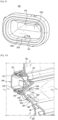
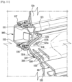
- a guide plate 221 may include a guide groove 226 formed in a first guide 224.
- FIG. 11 is a view illustrating an embodiment of the guide plate of FIG. 5 .
- a guide plate 321 may include a guide rib 326 formed in a first guide 324 and a water channel 327 formed between the guide ribs 326.
- the water channel 327 may be formed between the guide ribs 326.
- the guide rib 326 may be arranged to form the water channel 327 at a position corresponding to the condensed water outlet 114.
- the water channel 327 may guide the condensed water, which is discharged from the condensed water outlet 114, to the drain hole 122.
Landscapes
- Engineering & Computer Science (AREA)
- Textile Engineering (AREA)
- Detail Structures Of Washing Machines And Dryers (AREA)
- Accessory Of Washing/Drying Machine, Commercial Washing/Drying Machine, Other Washing/Drying Machine (AREA)
Claims (12)
- Appareil d'entretien de vêtements comprenant :un corps (10) comprenant un compartiment d'entretien de vêtements (30) et une partie technique (40) disposée sous le compartiment d'entretien de vêtements (30) ;un dispositif de génération de vapeur (70) conçu pour générer de la vapeur ;un injecteur de vapeur (100) comprenant :une surface inférieure (111c, 211c) inclinée vers le bas en direction du compartiment d'entretien de vêtements (30),un orifice d'injection de vapeur (113a) configuré pour recevoir la vapeur provenant du dispositif de génération de vapeur (70) et injecter la vapeur dans un intérieur du compartiment d'entretien de vêtements (30), etune sortie d'eau condensée (114) inclinée vers le bas en direction du compartiment d'entretien de vêtements (30) et configurée pour évacuer l'eau condensée issue de la vapeur à l'intérieur du compartiment d'entretien de vêtements (30), dans lequel l'orifice d'injection de vapeur (113a) est disposé au-dessus de la sortie d'eau condensée (114) ; etun trou d'évacuation (122) prévu dans le compartiment d'entretien de vêtements (30) au-dessous de la sortie d'eau condensée (114) pour connecter le compartiment d'entretien de vêtements (30) à la partie technique (40) pour permettre à l'eau condensée d'être évacuée depuis la sortie d'eau condensée (114) pour s'écouler dans la partie technique (40).
- Appareil d'entretien de vêtements selon la revendication 1, comprenant en outre une plaque de guidage (121, 221, 321) prévue dans le compartiment d'entretien de vêtements (30) au-dessous de la sortie d'eau condensée (114) pour guider l'eau condensée évacuée de la sortie d'eau condensée (114) vers le trou d'évacuation (122).
- Appareil d'entretien de vêtements selon la revendication 1, dans lequel l'injecteur de vapeur (100) comprend :une buse à vapeur (111) dans laquelle l'orifice d'injection de vapeur (113a) et la sortie d'eau condensée (114) sont formés ;un capot de buse (112) couplé à la buse à vapeur (111) ; etun premier élément d'étanchéité (116) disposé entre la buse à vapeur (111) et le capot de buse (112).
- Appareil d'entretien de vêtements selon la revendication 2, comprenant en outre un conduit (33, 34) disposé à l'intérieur de la partie technique (40),
dans lequel la plaque de guidage (121, 221, 321) comprend :un premier guide (124, 224, 324) incliné vers le bas en direction du trou d'évacuation (122) et configuré pour guider l'eau condensée évacuée de la sortie d'eau condensée (114) vers le trou d'évacuation (122) ; etun second guide (125) configuré pour guider l'eau condensée du trou d'évacuation (122) vers le conduit (33, 34). - Appareil d'entretien de vêtements selon la revendication 4, dans lequel le compartiment d'entretien de vêtements (30) comprend une première entrée de flux d'air (31a) et une première sortie de flux d'air (31b),
dans lequel le conduit (33, 34) comprend :un premier conduit (33) connecté à la première entrée de flux d'air (31a) dans laquelle l'air du compartiment d'entretien de vêtements (30) s'écoule dans le premier conduit (33), etun second conduit (34) connecté au premier conduit (33) et à la première sortie de flux d'air (31b), etdans lequel la première sortie de flux d'air (31b) est configurée pour évacuer l'air du second conduit (34) vers le compartiment d'entretien de vêtements (30). - Appareil d'entretien de vêtements selon la revendication 5, dans lequel le conduit (33, 34) comprend :un orifice de communication (35a) configuré pour connecter le premier conduit (33) au second conduit (34) ; etun élément de connexion (34a) pour connecter le premier conduit (33) au second conduit (34) afin d'évacuer l'eau condensée du second conduit (34) vers le premier conduit (33).
- Appareil d'entretien de vêtements selon la revendication 6, comprenant en outre un réservoir d'évacuation d'eau (61) disposé à l'intérieur de la partie technique (40) et connecté au premier conduit (33) pour collecter l'eau condensée provenant du premier conduit (33).
- Appareil d'entretien de vêtements selon la revendication 5, dans lequel une première extrémité (124, 224, 324) de la plaque de guidage (121, 221, 321) est couplée à l'injecteur de vapeur (100), et
une seconde extrémité (125) de la plaque de guidage (121, 221, 321) est couplée au second conduit (34). - Appareil d'entretien de vêtements selon la revendication 1, comprenant en outre un second élément d'étanchéité (117) disposé entre l'injecteur de vapeur (100) et le corps (10).
- Appareil d'entretien de vêtements selon la revendication 2, dans lequel la plaque de guidage (221) comprend une rainure de guidage évidée (226) pour former un canal d'eau (227) configuré pour guider l'eau condensée évacuée de la sortie d'eau condensée (114) vers la partie technique (40).
- Appareil d'entretien de vêtements selon la revendication 2, dans lequel la plaque de guidage (321) comprend une pluralité de nervures de guidage saillantes (326) pour former un canal d'eau (327) configuré pour guider l'eau condensée évacuée de la sortie d'eau condensée (114) vers la partie technique (40).
- Appareil d'entretien de vêtements selon la revendication 2, comprenant en outre un capot de plaque (131) configuré pour couvrir un écoulement de l'eau condensée dans la plaque de guidage (121, 221, 321).
Priority Applications (1)
| Application Number | Priority Date | Filing Date | Title |
|---|---|---|---|
| EP23205934.5A EP4290005A3 (fr) | 2018-09-12 | 2019-09-10 | Appareil de soins de vêtements |
Applications Claiming Priority (2)
| Application Number | Priority Date | Filing Date | Title |
|---|---|---|---|
| KR1020180109234A KR102650961B1 (ko) | 2018-09-12 | 2018-09-12 | 의류 관리기 |
| PCT/KR2019/011751 WO2020055116A1 (fr) | 2018-09-12 | 2019-09-10 | Appareil d'entretien de vêtements |
Related Child Applications (2)
| Application Number | Title | Priority Date | Filing Date |
|---|---|---|---|
| EP23205934.5A Division-Into EP4290005A3 (fr) | 2018-09-12 | 2019-09-10 | Appareil de soins de vêtements |
| EP23205934.5A Division EP4290005A3 (fr) | 2018-09-12 | 2019-09-10 | Appareil de soins de vêtements |
Publications (5)
| Publication Number | Publication Date |
|---|---|
| EP3814567A1 EP3814567A1 (fr) | 2021-05-05 |
| EP3814567A4 EP3814567A4 (fr) | 2021-08-18 |
| EP3814567B1 true EP3814567B1 (fr) | 2023-12-13 |
| EP3814567C0 EP3814567C0 (fr) | 2023-12-13 |
| EP3814567B8 EP3814567B8 (fr) | 2024-03-06 |
Family
ID=69719067
Family Applications (2)
| Application Number | Title | Priority Date | Filing Date |
|---|---|---|---|
| EP23205934.5A Pending EP4290005A3 (fr) | 2018-09-12 | 2019-09-10 | Appareil de soins de vêtements |
| EP19858781.8A Active EP3814567B8 (fr) | 2018-09-12 | 2019-09-10 | Appareil d'entretien de vêtements |
Family Applications Before (1)
| Application Number | Title | Priority Date | Filing Date |
|---|---|---|---|
| EP23205934.5A Pending EP4290005A3 (fr) | 2018-09-12 | 2019-09-10 | Appareil de soins de vêtements |
Country Status (5)
| Country | Link |
|---|---|
| US (1) | US11319664B2 (fr) |
| EP (2) | EP4290005A3 (fr) |
| KR (1) | KR102650961B1 (fr) |
| CN (1) | CN112714811B (fr) |
| WO (1) | WO2020055116A1 (fr) |
Families Citing this family (23)
| Publication number | Priority date | Publication date | Assignee | Title |
|---|---|---|---|---|
| USD885773S1 (en) * | 2018-08-17 | 2020-06-02 | Samsung Electronics Co., Ltd. | Clothes hanger |
| KR102636141B1 (ko) * | 2019-02-28 | 2024-02-13 | 엘지전자 주식회사 | 의류 처리장치 |
| KR102847421B1 (ko) * | 2020-05-06 | 2025-08-18 | 엘지전자 주식회사 | 공기흡입부 조립체 및 이를 포함하는 의류 처리 장치 |
| CN114075768A (zh) | 2020-08-13 | 2022-02-22 | 漳州灿坤实业有限公司 | 一种排水装置和蒸汽烘干机 |
| KR20220109946A (ko) * | 2021-01-29 | 2022-08-05 | 삼성전자주식회사 | 신발 관리기 |
| CN215051469U (zh) * | 2021-03-19 | 2021-12-07 | 广州易家智能电子科技有限公司 | 衣架及衣物护理机 |
| EP4227484B1 (fr) | 2021-05-04 | 2025-05-21 | Samsung Electronics Co., Ltd. | Appareil d'entretien de chaussures |
| CN115726179A (zh) * | 2021-08-31 | 2023-03-03 | 无锡小天鹅电器有限公司 | 通风衣架及衣物护理设备 |
| KR102845092B1 (ko) * | 2021-11-30 | 2025-08-14 | 엘지전자 주식회사 | 의류처리장치 및 의류처리장치의 조립방법 |
| EP4438796A4 (fr) * | 2021-11-30 | 2025-03-19 | LG Electronics Inc. | Appareil de traitement de vêtements |
| CN114232302A (zh) * | 2021-12-06 | 2022-03-25 | 无锡小天鹅电器有限公司 | 一种蒸汽发生器、主机身及衣物护理机 |
| KR102774270B1 (ko) * | 2021-12-07 | 2025-02-26 | 엘지전자 주식회사 | 신발 관리기 |
| CN114369936B (zh) * | 2021-12-09 | 2023-05-16 | 内蒙古工业大学 | 一种用于服装制作的除皱定型装置 |
| KR102732606B1 (ko) * | 2021-12-17 | 2024-11-20 | 엘지전자 주식회사 | 신발 관리기 |
| KR102761933B1 (ko) * | 2021-12-17 | 2025-02-03 | 엘지전자 주식회사 | 신발 관리기 |
| USD1009392S1 (en) * | 2021-12-28 | 2023-12-26 | Samsung Electronics Co., Ltd. | Clothing care machine |
| USD1017150S1 (en) * | 2021-12-28 | 2024-03-05 | Samsung Electronics Co., Ltd. | Clothing care machine |
| US12402760B2 (en) * | 2021-12-29 | 2025-09-02 | Simon Velasquez | Towel warming assembly including fragrance door |
| CN118103562A (zh) * | 2022-02-08 | 2024-05-28 | 三星电子株式会社 | 衣物护理设备 |
| WO2023182620A1 (fr) * | 2022-03-22 | 2023-09-28 | 삼성전자주식회사 | Appareil de traitement de vêtements |
| KR102824492B1 (ko) * | 2022-06-30 | 2025-06-25 | 엘지전자 주식회사 | 의류처리장치 |
| BE1031943B1 (de) * | 2023-08-14 | 2025-04-11 | Miele & Cie | Wäschebehandlungsschrank mit Dampferzeuger |
| KR102873534B1 (ko) | 2024-08-20 | 2025-10-21 | (주)알씨와이랩 | 전동식 호흡보호구를 살균하는 장치 |
Family Cites Families (29)
| Publication number | Priority date | Publication date | Assignee | Title |
|---|---|---|---|---|
| US3752373A (en) | 1972-03-08 | 1973-08-14 | S Smith | Portable wardrobe refresher |
| KR100745418B1 (ko) * | 2004-11-16 | 2007-08-02 | 삼성전자주식회사 | 스팀발생장치를 갖춘 세탁기의 제어방법 |
| KR20060061974A (ko) * | 2004-12-02 | 2006-06-09 | 삼성전자주식회사 | 의류의 구김제거장치 및 그 방법 |
| KR100672340B1 (ko) * | 2006-03-31 | 2007-01-24 | 엘지전자 주식회사 | 건조장치 및 그 제어방법 |
| KR101209401B1 (ko) * | 2006-04-27 | 2012-12-06 | 엘지전자 주식회사 | 의류 재생 장치 |
| KR101218465B1 (ko) * | 2006-05-15 | 2013-01-04 | 엘지전자 주식회사 | 의류 재생 장치 및 그 제어 방법 |
| KR101220579B1 (ko) * | 2006-05-15 | 2013-01-10 | 엘지전자 주식회사 | 의류 재생 장치 |
| US8176656B2 (en) * | 2006-07-18 | 2012-05-15 | Lg Electronics Inc. | Laundry dryer |
| US7707859B2 (en) * | 2006-08-15 | 2010-05-04 | Whirlpool Corporation | Water supply control for a steam generator of a fabric treatment appliance |
| KR101306723B1 (ko) * | 2007-01-10 | 2013-09-10 | 엘지전자 주식회사 | 복합 의류 처리 장치 |
| KR101215449B1 (ko) * | 2007-05-16 | 2012-12-26 | 삼성전자주식회사 | 세탁기 |
| KR101387497B1 (ko) * | 2007-08-03 | 2014-04-21 | 엘지전자 주식회사 | 의류처리장치 |
| AU2008284594B2 (en) * | 2007-08-03 | 2012-05-03 | Lg Electronics Inc. | Clothes treating apparatus |
| KR101366273B1 (ko) * | 2007-08-03 | 2014-02-20 | 엘지전자 주식회사 | 의류처리장치 |
| KR101498027B1 (ko) * | 2008-04-01 | 2015-03-03 | 엘지전자 주식회사 | 의류처리장치 및 의류처리장치의 제어방법 |
| EP2055824B1 (fr) * | 2007-11-02 | 2014-07-30 | LG Electronics Inc. | Appareil de séchage |
| KR101430459B1 (ko) * | 2007-11-16 | 2014-08-18 | 엘지전자 주식회사 | 의류처리장치 |
| KR101435822B1 (ko) * | 2007-12-26 | 2014-08-29 | 엘지전자 주식회사 | 의류처리장치 |
| KR101467773B1 (ko) * | 2008-04-01 | 2014-12-03 | 엘지전자 주식회사 | 의류처리장치 및 의류처리장치의 제어방법 |
| US8296967B2 (en) * | 2008-12-09 | 2012-10-30 | Lg Electronics Inc. | Fabric treating apparatus |
| EP2623662B1 (fr) * | 2012-02-06 | 2018-04-04 | LG Electronics Inc. | Machine de blanchisserie et procédé de commande correspondant |
| EP2821540B1 (fr) * | 2013-07-03 | 2020-10-14 | Electrolux Appliances Aktiebolag | Appareil domestique de séchage du linge doté d'une unité de buse à vapeur |
| KR102225177B1 (ko) * | 2014-05-28 | 2021-03-10 | 코웨이 주식회사 | 제습기 |
| KR101597106B1 (ko) * | 2014-12-19 | 2016-03-07 | 엘지전자 주식회사 | 의류처리장치 |
| KR102369585B1 (ko) * | 2014-12-19 | 2022-03-04 | 엘지전자 주식회사 | 의류처리장치 |
| KR101597108B1 (ko) * | 2014-12-19 | 2016-02-24 | 엘지전자 주식회사 | 의류처리장치 |
| KR102369584B1 (ko) * | 2014-12-19 | 2022-03-03 | 엘지전자 주식회사 | 의류처리장치 |
| CN204825502U (zh) * | 2015-07-08 | 2015-12-02 | 华南理工大学 | 一种防止冷凝水滴落的蒸汽箱 |
| CN207031858U (zh) * | 2017-06-20 | 2018-02-23 | 无锡小天鹅股份有限公司 | 干衣机 |
-
2018
- 2018-09-12 KR KR1020180109234A patent/KR102650961B1/ko active Active
-
2019
- 2019-09-10 EP EP23205934.5A patent/EP4290005A3/fr active Pending
- 2019-09-10 CN CN201980060067.5A patent/CN112714811B/zh active Active
- 2019-09-10 EP EP19858781.8A patent/EP3814567B8/fr active Active
- 2019-09-10 WO PCT/KR2019/011751 patent/WO2020055116A1/fr not_active Ceased
- 2019-09-12 US US16/568,594 patent/US11319664B2/en active Active
Also Published As
| Publication number | Publication date |
|---|---|
| CN112714811A (zh) | 2021-04-27 |
| KR102650961B1 (ko) | 2024-03-26 |
| WO2020055116A1 (fr) | 2020-03-19 |
| EP3814567B8 (fr) | 2024-03-06 |
| US20200080254A1 (en) | 2020-03-12 |
| EP4290005A3 (fr) | 2024-02-28 |
| CN112714811B (zh) | 2023-07-18 |
| KR20200030404A (ko) | 2020-03-20 |
| EP4290005A2 (fr) | 2023-12-13 |
| EP3814567C0 (fr) | 2023-12-13 |
| US11319664B2 (en) | 2022-05-03 |
| EP3814567A1 (fr) | 2021-05-05 |
| EP3814567A4 (fr) | 2021-08-18 |
Similar Documents
| Publication | Publication Date | Title |
|---|---|---|
| US11319664B2 (en) | Clothes care apparatus | |
| US12012689B2 (en) | Clothing care system | |
| US8230613B2 (en) | Clothes treating apparatus | |
| US11542651B2 (en) | Clothes care apparatus | |
| AU2007277599C1 (en) | Multiple laundry treating machine and control method thereof | |
| KR102747204B1 (ko) | 의류 관리기 | |
| KR102802036B1 (ko) | 의류 관리기 | |
| US11459697B2 (en) | Clothes care apparatus | |
| US12203207B2 (en) | Clothes care apparatus | |
| EP3569758A1 (fr) | Appareil de traitement de vêtements | |
| KR20060038796A (ko) | 의류건조기 일체형 세탁 장치 | |
| US11313070B2 (en) | Clothes care apparatus | |
| AU2007277518A1 (en) | Multiple laundry treating machine | |
| EP2213781B1 (fr) | Appareil de traitement de vêtements | |
| KR20250078883A (ko) | 의류처리장치 | |
| KR102758868B1 (ko) | 주름관리기 및 이를 포함하는 의류관리기 | |
| US12024811B2 (en) | Air inlet assembly and laundry treatment apparatus including the same | |
| KR102824492B1 (ko) | 의류처리장치 | |
| KR101486358B1 (ko) | 의류처리장치 | |
| KR102845094B1 (ko) | 의류처리장치 | |
| EP4438796A1 (fr) | Appareil de traitement de vêtements |
Legal Events
| Date | Code | Title | Description |
|---|---|---|---|
| STAA | Information on the status of an ep patent application or granted ep patent |
Free format text: STATUS: THE INTERNATIONAL PUBLICATION HAS BEEN MADE |
|
| PUAI | Public reference made under article 153(3) epc to a published international application that has entered the european phase |
Free format text: ORIGINAL CODE: 0009012 |
|
| STAA | Information on the status of an ep patent application or granted ep patent |
Free format text: STATUS: REQUEST FOR EXAMINATION WAS MADE |
|
| 17P | Request for examination filed |
Effective date: 20210126 |
|
| AK | Designated contracting states |
Kind code of ref document: A1 Designated state(s): AL AT BE BG CH CY CZ DE DK EE ES FI FR GB GR HR HU IE IS IT LI LT LU LV MC MK MT NL NO PL PT RO RS SE SI SK SM TR |
|
| A4 | Supplementary search report drawn up and despatched |
Effective date: 20210721 |
|
| RIC1 | Information provided on ipc code assigned before grant |
Ipc: D06F 58/24 20060101AFI20210715BHEP Ipc: D06F 73/02 20060101ALI20210715BHEP Ipc: D06F 58/10 20060101ALN20210715BHEP Ipc: D06F 58/20 20060101ALN20210715BHEP |
|
| DAV | Request for validation of the european patent (deleted) | ||
| DAX | Request for extension of the european patent (deleted) | ||
| GRAP | Despatch of communication of intention to grant a patent |
Free format text: ORIGINAL CODE: EPIDOSNIGR1 |
|
| STAA | Information on the status of an ep patent application or granted ep patent |
Free format text: STATUS: GRANT OF PATENT IS INTENDED |
|
| RIC1 | Information provided on ipc code assigned before grant |
Ipc: D06F 58/20 20060101ALN20230601BHEP Ipc: D06F 58/10 20060101ALN20230601BHEP Ipc: D06F 73/02 20060101ALI20230601BHEP Ipc: D06F 58/24 20060101AFI20230601BHEP |
|
| INTG | Intention to grant announced |
Effective date: 20230704 |
|
| GRAS | Grant fee paid |
Free format text: ORIGINAL CODE: EPIDOSNIGR3 |
|
| GRAA | (expected) grant |
Free format text: ORIGINAL CODE: 0009210 |
|
| STAA | Information on the status of an ep patent application or granted ep patent |
Free format text: STATUS: THE PATENT HAS BEEN GRANTED |
|
| AK | Designated contracting states |
Kind code of ref document: B1 Designated state(s): AL AT BE BG CH CY CZ DE DK EE ES FI FR GB GR HR HU IE IS IT LI LT LU LV MC MK MT NL NO PL PT RO RS SE SI SK SM TR |
|
| REG | Reference to a national code |
Ref country code: GB Ref legal event code: FG4D |
|
| REG | Reference to a national code |
Ref country code: CH Ref legal event code: EP |
|
| REG | Reference to a national code |
Ref country code: DE Ref legal event code: R096 Ref document number: 602019043371 Country of ref document: DE |
|
| REG | Reference to a national code |
Ref country code: IE Ref legal event code: FG4D |
|
| GRAT | Correction requested after decision to grant or after decision to maintain patent in amended form |
Free format text: ORIGINAL CODE: EPIDOSNCDEC |
|
| U01 | Request for unitary effect filed |
Effective date: 20240105 |
|
| REG | Reference to a national code |
Ref country code: CH Ref legal event code: PK Free format text: BERICHTIGUNG B8 |
|
| RAP4 | Party data changed (patent owner data changed or rights of a patent transferred) |
Owner name: SAMSUNG ELECTRONICS CO., LTD. |
|
| U07 | Unitary effect registered |
Designated state(s): AT BE BG DE DK EE FI FR IT LT LU LV MT NL PT SE SI Effective date: 20240119 |
|
| PG25 | Lapsed in a contracting state [announced via postgrant information from national office to epo] |
Ref country code: GR Free format text: LAPSE BECAUSE OF FAILURE TO SUBMIT A TRANSLATION OF THE DESCRIPTION OR TO PAY THE FEE WITHIN THE PRESCRIBED TIME-LIMIT Effective date: 20240314 |
|
| PG25 | Lapsed in a contracting state [announced via postgrant information from national office to epo] |
Ref country code: ES Free format text: LAPSE BECAUSE OF FAILURE TO SUBMIT A TRANSLATION OF THE DESCRIPTION OR TO PAY THE FEE WITHIN THE PRESCRIBED TIME-LIMIT Effective date: 20231213 |
|
| PG25 | Lapsed in a contracting state [announced via postgrant information from national office to epo] |
Ref country code: GR Free format text: LAPSE BECAUSE OF FAILURE TO SUBMIT A TRANSLATION OF THE DESCRIPTION OR TO PAY THE FEE WITHIN THE PRESCRIBED TIME-LIMIT Effective date: 20240314 Ref country code: ES Free format text: LAPSE BECAUSE OF FAILURE TO SUBMIT A TRANSLATION OF THE DESCRIPTION OR TO PAY THE FEE WITHIN THE PRESCRIBED TIME-LIMIT Effective date: 20231213 |
|
| PG25 | Lapsed in a contracting state [announced via postgrant information from national office to epo] |
Ref country code: RS Free format text: LAPSE BECAUSE OF FAILURE TO SUBMIT A TRANSLATION OF THE DESCRIPTION OR TO PAY THE FEE WITHIN THE PRESCRIBED TIME-LIMIT Effective date: 20231213 Ref country code: NO Free format text: LAPSE BECAUSE OF FAILURE TO SUBMIT A TRANSLATION OF THE DESCRIPTION OR TO PAY THE FEE WITHIN THE PRESCRIBED TIME-LIMIT Effective date: 20240313 Ref country code: HR Free format text: LAPSE BECAUSE OF FAILURE TO SUBMIT A TRANSLATION OF THE DESCRIPTION OR TO PAY THE FEE WITHIN THE PRESCRIBED TIME-LIMIT Effective date: 20231213 |
|
| PG25 | Lapsed in a contracting state [announced via postgrant information from national office to epo] |
Ref country code: IS Free format text: LAPSE BECAUSE OF FAILURE TO SUBMIT A TRANSLATION OF THE DESCRIPTION OR TO PAY THE FEE WITHIN THE PRESCRIBED TIME-LIMIT Effective date: 20240413 |
|
| PG25 | Lapsed in a contracting state [announced via postgrant information from national office to epo] |
Ref country code: CZ Free format text: LAPSE BECAUSE OF FAILURE TO SUBMIT A TRANSLATION OF THE DESCRIPTION OR TO PAY THE FEE WITHIN THE PRESCRIBED TIME-LIMIT Effective date: 20231213 |
|
| PG25 | Lapsed in a contracting state [announced via postgrant information from national office to epo] |
Ref country code: SK Free format text: LAPSE BECAUSE OF FAILURE TO SUBMIT A TRANSLATION OF THE DESCRIPTION OR TO PAY THE FEE WITHIN THE PRESCRIBED TIME-LIMIT Effective date: 20231213 |
|
| PG25 | Lapsed in a contracting state [announced via postgrant information from national office to epo] |
Ref country code: SM Free format text: LAPSE BECAUSE OF FAILURE TO SUBMIT A TRANSLATION OF THE DESCRIPTION OR TO PAY THE FEE WITHIN THE PRESCRIBED TIME-LIMIT Effective date: 20231213 Ref country code: SK Free format text: LAPSE BECAUSE OF FAILURE TO SUBMIT A TRANSLATION OF THE DESCRIPTION OR TO PAY THE FEE WITHIN THE PRESCRIBED TIME-LIMIT Effective date: 20231213 Ref country code: RO Free format text: LAPSE BECAUSE OF FAILURE TO SUBMIT A TRANSLATION OF THE DESCRIPTION OR TO PAY THE FEE WITHIN THE PRESCRIBED TIME-LIMIT Effective date: 20231213 Ref country code: IS Free format text: LAPSE BECAUSE OF FAILURE TO SUBMIT A TRANSLATION OF THE DESCRIPTION OR TO PAY THE FEE WITHIN THE PRESCRIBED TIME-LIMIT Effective date: 20240413 Ref country code: CZ Free format text: LAPSE BECAUSE OF FAILURE TO SUBMIT A TRANSLATION OF THE DESCRIPTION OR TO PAY THE FEE WITHIN THE PRESCRIBED TIME-LIMIT Effective date: 20231213 |
|
| PG25 | Lapsed in a contracting state [announced via postgrant information from national office to epo] |
Ref country code: PL Free format text: LAPSE BECAUSE OF FAILURE TO SUBMIT A TRANSLATION OF THE DESCRIPTION OR TO PAY THE FEE WITHIN THE PRESCRIBED TIME-LIMIT Effective date: 20231213 |
|
| PG25 | Lapsed in a contracting state [announced via postgrant information from national office to epo] |
Ref country code: PL Free format text: LAPSE BECAUSE OF FAILURE TO SUBMIT A TRANSLATION OF THE DESCRIPTION OR TO PAY THE FEE WITHIN THE PRESCRIBED TIME-LIMIT Effective date: 20231213 |
|
| REG | Reference to a national code |
Ref country code: DE Ref legal event code: R097 Ref document number: 602019043371 Country of ref document: DE |
|
| PLBE | No opposition filed within time limit |
Free format text: ORIGINAL CODE: 0009261 |
|
| STAA | Information on the status of an ep patent application or granted ep patent |
Free format text: STATUS: NO OPPOSITION FILED WITHIN TIME LIMIT |
|
| U20 | Renewal fee for the european patent with unitary effect paid |
Year of fee payment: 6 Effective date: 20240923 |
|
| 26N | No opposition filed |
Effective date: 20240916 |
|
| PG25 | Lapsed in a contracting state [announced via postgrant information from national office to epo] |
Ref country code: MC Free format text: LAPSE BECAUSE OF FAILURE TO SUBMIT A TRANSLATION OF THE DESCRIPTION OR TO PAY THE FEE WITHIN THE PRESCRIBED TIME-LIMIT Effective date: 20231213 |
|
| REG | Reference to a national code |
Ref country code: CH Ref legal event code: PL |
|
| PG25 | Lapsed in a contracting state [announced via postgrant information from national office to epo] |
Ref country code: CH Free format text: LAPSE BECAUSE OF NON-PAYMENT OF DUE FEES Effective date: 20240930 |
|
| PG25 | Lapsed in a contracting state [announced via postgrant information from national office to epo] |
Ref country code: IE Free format text: LAPSE BECAUSE OF NON-PAYMENT OF DUE FEES Effective date: 20240910 |
|
| PGFP | Annual fee paid to national office [announced via postgrant information from national office to epo] |
Ref country code: GB Payment date: 20250820 Year of fee payment: 7 |
|
| U20 | Renewal fee for the european patent with unitary effect paid |
Year of fee payment: 7 Effective date: 20250924 |
|
| PG25 | Lapsed in a contracting state [announced via postgrant information from national office to epo] |
Ref country code: CY Free format text: LAPSE BECAUSE OF FAILURE TO SUBMIT A TRANSLATION OF THE DESCRIPTION OR TO PAY THE FEE WITHIN THE PRESCRIBED TIME-LIMIT; INVALID AB INITIO Effective date: 20190910 |
|
| PG25 | Lapsed in a contracting state [announced via postgrant information from national office to epo] |
Ref country code: HU Free format text: LAPSE BECAUSE OF FAILURE TO SUBMIT A TRANSLATION OF THE DESCRIPTION OR TO PAY THE FEE WITHIN THE PRESCRIBED TIME-LIMIT; INVALID AB INITIO Effective date: 20190910 |