EP3814603B1 - Verfahren und vorrichtung zum entfernen von abschnitten einer bohrlochwand - Google Patents
Verfahren und vorrichtung zum entfernen von abschnitten einer bohrlochwand Download PDFInfo
- Publication number
- EP3814603B1 EP3814603B1 EP19826150.5A EP19826150A EP3814603B1 EP 3814603 B1 EP3814603 B1 EP 3814603B1 EP 19826150 A EP19826150 A EP 19826150A EP 3814603 B1 EP3814603 B1 EP 3814603B1
- Authority
- EP
- European Patent Office
- Prior art keywords
- downhole tool
- casing
- cutters
- feature
- cutting head
- Prior art date
- Legal status (The legal status is an assumption and is not a legal conclusion. Google has not performed a legal analysis and makes no representation as to the accuracy of the status listed.)
- Active
Links
Images




Classifications
-
- E—FIXED CONSTRUCTIONS
- E21—EARTH OR ROCK DRILLING; MINING
- E21B—EARTH OR ROCK DRILLING; OBTAINING OIL, GAS, WATER, SOLUBLE OR MELTABLE MATERIALS OR A SLURRY OF MINERALS FROM WELLS
- E21B23/00—Apparatus for displacing, setting, locking, releasing or removing tools, packers or the like in boreholes or wells
- E21B23/14—Apparatus for displacing, setting, locking, releasing or removing tools, packers or the like in boreholes or wells for displacing a cable or a cable-operated tool, e.g. for logging or perforating operations in deviated wells
-
- E—FIXED CONSTRUCTIONS
- E21—EARTH OR ROCK DRILLING; MINING
- E21B—EARTH OR ROCK DRILLING; OBTAINING OIL, GAS, WATER, SOLUBLE OR MELTABLE MATERIALS OR A SLURRY OF MINERALS FROM WELLS
- E21B10/00—Drill bits
- E21B10/26—Drill bits with leading portion, i.e. drill bits with a pilot cutter; Drill bits for enlarging the borehole, e.g. reamers
-
- E—FIXED CONSTRUCTIONS
- E21—EARTH OR ROCK DRILLING; MINING
- E21B—EARTH OR ROCK DRILLING; OBTAINING OIL, GAS, WATER, SOLUBLE OR MELTABLE MATERIALS OR A SLURRY OF MINERALS FROM WELLS
- E21B23/00—Apparatus for displacing, setting, locking, releasing or removing tools, packers or the like in boreholes or wells
- E21B23/01—Apparatus for displacing, setting, locking, releasing or removing tools, packers or the like in boreholes or wells for anchoring the tools or the like
-
- E—FIXED CONSTRUCTIONS
- E21—EARTH OR ROCK DRILLING; MINING
- E21B—EARTH OR ROCK DRILLING; OBTAINING OIL, GAS, WATER, SOLUBLE OR MELTABLE MATERIALS OR A SLURRY OF MINERALS FROM WELLS
- E21B29/00—Cutting or destroying pipes, packers, plugs or wire lines, located in boreholes or wells, e.g. cutting of damaged pipes, of windows; Deforming of pipes in boreholes or wells; Reconditioning of well casings while in the ground
- E21B29/002—Cutting, e.g. milling, a pipe with a cutter rotating along the circumference of the pipe
- E21B29/005—Cutting, e.g. milling, a pipe with a cutter rotating along the circumference of the pipe with a radially-expansible cutter rotating inside the pipe, e.g. for cutting an annular window
Definitions
- This disclosure relates to systems and methods for performing machining operations within a wellbore using downhole tools.
- machining operations on a casing or other component disposed within a wellbore. For example, it may be desirable to machine a portion of the casing to facilitate plug and abandon operations of the wellbore. Unfortunately, it may be difficult to effectively perform machining operations on the casing due to spatial constraints within the wellbore.
- US 2007/251687 A1 describes a tool for use inside a wellbore including an intervention module capable of performing an intervention operation downhole, and a drive electronics module configured to control the intervention module and one or more sensors which measure at least one operational parameter during the intervention operation. The intervention operation is optimized based on the measured operational parameter.
- US 2006/231258 A1 describes a remotely controlled tool for cutting through a tubular at a selected location in a wellbore, the tool comprising a tool body, a cutting head provided with a cutting means, the cutting head being pivotally mounted on the tool body at or near the lower end thereof, an electrically actuatable means for pivoting the cutting head, and an elongate arm to urge the cutting means of the cutting head against the wall of the tubular.
- EP1076758 A1 describes a tool for milling an opening in a well casing having a stationary housing anchored to the casing, a hydraulic motor having a stationary part secured to the housing, a milling tool rotationally secured to a rotating part of the hydraulic motor and slideable in the longitudinal direction of the well relative to the housing and a transfer mechanism for transferring motion in the longitudinal direction of the well between a coil tubing suspending the housing and the milling tool for forcing the milling tool upwards in the well by pulling the coil tubing.
- US2002/162659 describes an apparatus for milling a section of casing in an upward direction, utilizing a downhole hydraulic thrusting mechanism for pulling a section mill upwardly.
- a downhole motor and torque anchor can be used to rotate the section mill, or the mill can be rotated by a work string.
- a stabilizer above the section mill can be used to stabilize the mill relative to the casing being milled.
- a spiral auger below the section mill can be used to move the cuttings downwardly.
- the present invention resides in a downhole tool as defined in claim 1 a wireline system as defined in claim 12 and a method as defined in claim 15. Preferred embodiments are defined in the dependent claims.
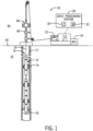
- FIG. 1 illustrates a wireline system 10 that may employ the systems and methods of this disclosure.
- the wireline system 10 may be used to convey a downhole tool 12 through a geological formation 14 via a wellbore 16.
- a casing 17 may be disposed within the wellbore 16, such that the downhole tool 12 may traverse the wellbore 16 within the casing 17.
- a cement lining 19 may be positioned between the casing 17 and the geological formation 14, such that the casing 17 is cemented (e.g., affixed to) the surrounding geological formation 14.
- the casing 17 and the cement lining 19 may be referred to as respective "features" of the wellbore 16.
- the downhole tool 12 may be conveyed through the wellbore 16 via a cable 18 of the wireline system 10.
- the wireline system 10 may be substantially fixed (e.g., a long-term installation that is substantially permanent or modular) or may be a mobile wireline system, such as a wireline system carried by a truck. Any suitable cable 18 may be used to convey the downhole tool 12 through the wellbore 16.
- the cable 18 may be spooled and unspooled on a drum 22 of the wireline system 10.
- a power unit 24 may provide energy (e.g., electrical energy) to the wireline system 10 and/or the downhole tool 12.
- the wireline system 10 may include a data processing system 28 that may control operations of the wireline system 10 and/or the downhole tool 12 in accordance with techniques discussed herein. Indeed, as discussed in detail below, the data processing system 28 may enable autonomous operation of the downhole tool 12 within the wellbore 16.
- the data processing system 28 includes a processor 30, which may execute instructions stored in a memory 32.
- the memory 32 may be any suitable article of manufacture that can store the instructions.
- the memory 32 and may be ROM memory, random-access memory (RAM), flash memory, an optical storage medium, or a hard disk drive, to name a few examples.
- the wireline system 10 includes wellbore equipment or pressure control equipment 38 disposed near a surface 40 of the geological formation 14.
- the pressure control equipment 38 enables the cable 18 to move the downhole tool 12 through the wellbore 16, while substantially blocking pressurized fluid within the wellbore 16 from leaking into an ambient environment 44 (e.g., the atmosphere).
- the pressure control equipment 38 includes a pack-off 48 that may form a fluidic seal around the cable 18.
- the cable 18 may pass through an annular opening within the pack-off 48 that may conform to an external surface of the cable 18, thus forming the fluid seal.
- the pack-off 48 may mitigate wellbore fluids or other contaminants, such as grease, from entering the wellbore 16 or discharging from the wellbore 16.
- the pressure control equipment 38 may include any other suitable components or combination of components that may facilitate traversing the cable 18 and the downhole tool 12 through the wellbore 16. That is, the pressure control equipment 38 may additionally include, for example, a lubricator, a tool trap, a pump-in-sub, a cable shearing device, one or more motorized rollers, or any other suitable component(s).
- embodiments of the downhole tool 12 discussed herein are equipped with a cutting head 50 that is operable to selectively remove one or more sections of the casing 17 and/or one or more sections of the cement lining 19 from the wellbore 16.
- FIG. 2 is a schematic of an embodiment of the downhole tool 12.
- the downhole tool 12 includes a logging head 52 that couples the downhole tool 12 to the cable 18.
- the logging head 52 houses a cable tension sensor and a release device.
- the release device may be operable to detach the downhole tool 12 from the cable 18.
- the cable tension sensor and the release device may be communicatively coupled to, for example, the data processing system 28.
- the downhole tool 12 may include a swivel 54 that is coupled to the logging head 52 at a first end portion 56 of the swivel 54.
- the swivel 54 may rotate or swivel relative to the logging head 52 (e.g., about a central axis 53 of the downhole tool 12). Accordingly, the swivel 54 may ensure that components of the downhole tool 12 that are coupled to a second end portion 58 of the swivel 54 may rotate or swivel relative to the logging head 52 without imparting a torque on the cable 18.
- the downhole tool 12 includes a telemetry module 60, also referred to herein as a control system, which is coupled to the second end portion 58 of the swivel 54.
- the telemetry module 60 may include sensors that transmit real-time data indicative of one or more operational parameters of the downhole tool 12 to the data processing system 28. Additionally, the telemetry module 60 may enable remote control of the downhole tool 12 via instructions provided by the processor 30 and/or an operator (e.g., a wireline operator) of the wireline system 10.
- the telemetry module 60 may be coupled to a power electronics module 66.
- the power electronics module 66 may include batteries for providing electrical power to one or more components of the downhole tool 12.
- the power electronics module 66 may distribute electrical power provided by the power unit 24 (e.g., via the electrical lines embedded in the cable 18) to various sensors, actuators, motors, or other components of the downhole tool 12.
- the power electronics module 66 may provide power (e.g., electrical power) that is used to operate one or more hydraulic pumps included in a hydraulic module 70 of the downhole tool 12.
- the hydraulic module 70 may be coupled to the power electronics module 66.
- the one or more hydraulic pumps of the hydraulic module 70 may be operable to provide a flow of pressurized hydraulic fluid to various actuators and/or motors of the downhole tool 12.
- the hydraulic module 70 may provide a flow of pressurized hydraulic fluid to a hydraulic motor of the cutting head 50, such that the hydraulic motor may rotate the cutting head 50 about the central axis 53 of the downhole tool 12 (e.g., relative to the casing 17).
- the hydraulic module 70 may also provide pressurized hydraulic fluid to an anchor 72, a linear actuator 74, and/or one or more centralizers 76 that may be included in the downhole tool 12.
- the downhole tool 12 includes a compensator 80 that may serve as a hydraulic fluid reservoir for the hydraulic module 70. Additionally or alternatively, the compensator 80 may operate to provide pressure compensation to various hydraulically actuated components of the downhole tool 12, such as, for example, the anchor 72, the linear actuator 74, and/or the one or more centralizers 76.
- the anchor 72 may include one or more legs 90 that are selectively extendable from the anchor 72 in a direction that extends generally outward (e.g., radially outward) from the central axis 53 of the downhole tool 12. Accordingly, the legs 90 may engage with the casing 17, the cement lining 19, or the geological formation 14. Particularly, in an extended position, the legs 90 may block rotational motion (e.g., about the central axis 53) and/or linear movement (e.g., along the central axis 53) of the anchor 72 relative to the casing 17. The legs 90 may be transitionable between the extended position and a retracted position by regulating a flow of hydraulic fluid supplied to the anchor 72 via the hydraulic module 70.
- the legs 90 may be transitionable between the extended position and a retracted position by regulating a flow of hydraulic fluid supplied to the anchor 72 via the hydraulic module 70.
- the downhole tool 12 includes a single anchor 72, it should be understood that, in other embodiments, the downhole tool 12 may include a plurality of anchors 72 that are located at various portions of the downhole tool 12, such as near the logging head 52 and/or near the cutting head 50.
- the linear actuator 74 includes a piston 100 (e.g., or multiple pistons) that may extend from or retract into a body 102 of the linear actuator 74 (e.g., via regulation of a hydraulic fluid flow to the linear actuator 74). As discussed in detail below, the linear actuator 74 may therefore enable translational movement of an upper body 104 of the downhole tool 12 relative to a lower body 106 of the downhole tool 12.
- the upper body 104 may include components of the downhole tool 12 that are positioned between a lower end 108 of the linear actuator 74 and the logging head 52.
- the lower body 106 may include components of the downhole tool 12 that are positioned between an upper end 110 of a first centralizer 111 of the centralizers 76 and the cutting head 50.
- the piston 100 may be configured to block rotational motion (e.g., about the central axis 53) of the lower body 106 relative to the upper body 104.
- the piston 100 may house various hydraulic lines and/or electrical lines that may provide hydraulic fluid and/or electrical power to certain components of the lower body 106, such as the centralizers 76.
- the piston 100 may include a hollow interior region or passage that enables conduits, tubes, wires, or other connection features to extend between components of the upper body 104 and components of the lower body 106.
- the one or more centralizers 76 may be transitionable between a retracted position, in which the centralizers 76 do not engage with the casing 17, and an extended position, in which rollers 216 of the centralizer 76 engage (e.g., contact) a surface of the casing 17.
- the centralizers 76 may be passive components that are permanently positioned in the extended position. While shown with rollers 216 in the present embodiment, in other embodiments, the centralizers 76 may not include rollers. In any case, the centralizers 76 may align the downhole tool 12 concentrically within the casing 17.
- the rollers 120 may enable the lower body 106 of the downhole tool 12 to translate axially along the casing 17 while the centralizers 76 are in the extended position. In this manner, the centralizers 76 may facilitate the operation of the downhole tool 12 as discussed below.
- the downhole tool 12 includes a motor 122 and a gearbox 124 that are coupled to and positioned between the centralizers 76.
- the motor 122 and the gearbox 124 are cooperatively operable to impart a torque on the cutting head 50 that is sufficient to rotate the cutting head 50 (e.g., about the central axis 53) relative to a remaining portion of the downhole tool 12.
- the hydraulic module 70 may supply a flow of pressurized hydraulic fluid to the motor 122 that enables the motor 122 to drive rotation of the cutting head 50.
- the cutting head 50 may include one or more knives 130 (e.g., cutting tools, cutters) that are selectively extendable between a retracted position, in which the knives 130 do not engage with the casing 17 and/or the cement lining 19, and an extended position, in which the knives 130 engage (e.g., contact) the casing 17, the cement lining 19, or both. Accordingly, in the extended position, the knives 130 may cut into the casing 17 and/or the cement lining 19 when the cutting head 50 rotates about the central axis 53, thereby enabling the knives 130 to remove (e.g., via machining such as cutting, abrasion) a section of the casing 17 and/or the cement lining 19 that is in contact with the knives 130.
- knives 130 e.g., cutting tools, cutters
- FIG. 3 is a schematic diagram of another embodiment of the downhole tool 12.
- the downhole tool 12 includes a pair of cutting heads 50 (e.g., a first cutting head 182 and a second cutting head 184) that may be used individually or concurrently to remove sections of the casing 17 and/or the cement lining 19.
- downhole tool 12 may include any suitable quantity of cutting heads 50 that are operable to perform machining operations (e.g., cutting, grinding, drilling) on the casing 17 and/or the cement lining 19.
- the cutting heads 50 may be driven by the same motor 122 and the same gearbox 124.
- each of the cutting heads 50 may include a dedicated motor and a dedicated gearbox that is configured to drive rotation that particular cutting head.
- the second cutting head 184 may be driven by an additional motor 186 and an additional gearbox 188.
- FIG. 4 is a block diagram of another embodiment of the downhole tool 12.
- the downhole tool 12 includes a plurality of linear actuators 74, a plurality of anchors 72, and a plurality of cutting heads 50.
- the downhole tool 12 may include any one or combination of the components discussed above, which may collectively form the downhole tool 12.
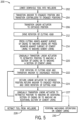
- FIG. 5 is a flow diagram of an embodiment of process 200 of operating the downhole tool 12.
- the following discussion references element numbers used throughout FIGS. 1-4 .
- the steps of the process 200 discussed below may be performed in any suitable order and are not limited to the order shown in the illustrated embodiment of FIG. 5 .
- additional steps of the process 200 may be performed and certain steps of the process 200 may be omitted.
- the process 200 may be executed on the processor 30 and/or any other suitable processor of the wireline system 10, such as a processor 199 (e.g., as shown in FIG. 2 ) included in the downhole tool 12.
- the process 200 may be stored on, for example, the memory 32 and/or any other suitable memory device of the wireline system 10, such as a memory 201 (e.g., as shown in FIG. 2 ) of the downhole tool 12.
- the process 200 may begin with lowering the downhole tool 12 into the wellbore 16 via the cable 18, as indicated by block 202.
- the cable 18 may be spooled or unspooled from the drum 22 to position the downhole tool 12 along a particular location in the wellbore 16.
- a weight of the downhole tool 12 and the cable 18 may be sufficient to unspool the cable 18 from the drum 22 to lower the downhole tool 12 into the wellbore 16.
- the downhole tool 12 and/or the pressure control equipment 38 may be equipped with a tractor tool (e.g., one or more motorized rollers) that are operable to force the downhole tool 12 and/or the cable 18 into the wellbore 16 to position the downhole tool 12 along a particular location in the wellbore 16.
- a tractor tool e.g., one or more motorized rollers
- the process 200 includes transitioning the anchor 72 to an engaged position, as indicated by block 204, upon positioned the downhole to at the desired location in the wellbore 16.
- the hydraulic module 70 may receive instructions (e.g., from the processor 30) to supply pressurized hydraulic fluid to the anchor 72, and thus, enable the legs 90 of the anchor to transition from a retracted position to an extended position, in which the legs 90 engage (e.g., contact) the casing 17, the cement lining 19, or another suitable portion of the wellbore 16.
- the anchor 72 may block rotational motion and/or translation movement of components of the upper body 104 of the downhole tool 12.
- the block 204 also includes transitioning the centralizers 76 to respective engaged positions, such that the centralizers 76 may center the lower body 106 of the downhole tool 12 within the casing 17.
- the processor 30 may instruct the linear actuator 74 to transition to an extended position, as indicated by block 206.
- the linear actuator 74 may be in a retracted positioned while the downhole tool 12 is lowered into the wellbore 16, during the block 202. Accordingly, by transitioning to the extended position at the block 206, the linear actuator 74 may space apart the lower body 106 of the downhole tool 12 from the upper body 104 of the downhole tool 12 by a distance 208 (e.g., as shown in FIG. 3 ). That is, the linear actuator 74 may force the lower body 106 in a first direction 210 (e.g., as shown in FIG.
- the linear actuator 74 may be positioned in the extended position while the downhole tool 12 is lowered into the wellbore 16.
- the process 200 includes driving rotation of the cutting head 50 about the central axis 53, relative to the wellbore 16, as indicated by block 212.
- the processor 30 may instruct the hydraulic module 70 to provide a flow of pressurized hydraulic fluid to the motor 122, such that the motor 122, via engagement of the gearbox 124, may drive rotation of the cutting head 50.
- the processor 30 may adjust a rotational speed of the cutting head 50 based on known characteristics of the wellbore 16 (e.g., based on a casing material used, based on a composition of the cement lining 19) or based on sensor feedback acquired by various sensors of the downhole tool 12.
- the process 200 includes pressing the knives 130 of the cutting head 50 against a surface (e.g., an interior surface) of the casing 17 to initiate machining of the casing 17, as indicated by block 214.
- the cutting head 50 may include one or more actuators (e.g., hydraulic actuators) that are operable to transition the knives 130 from a retracted position, in which the knives 130 do not engage the casing 17, to an extended position, in which the knives 130 engage (e.g., physically contact) the casing 17.
- the rotational motion of the knives 130 about the central axis 53 may enable the knives 130 to machine (e.g., cut, scrape, chip) the casing 17 to remove material from the casing 17.
- the cutting head 50 may continue to press the knives 130 against the casing 17 until the knives 130 machine through a thickness (e.g., a width) of the casing 17. Therefore, the knives 130 may form a circumferential slot within the casing 17.
- processor 30 may instruct the cutting head 50 to maintain a position of the knives 130 (e.g., a radial position of the knives 130 relative to the central axis 53) upon determining that the knives 130 have machined through the thickness of the casing 17.
- the processor 30 may determine when the knives 130 have fully cut through the casing 17 based on feedback from one or more sensors monitoring a force applied by the knives 130 to the casing 17. For example, a force applied by the knives 130 to the casing 17 may spike (e.g., suddenly increase or decrease) when the knives 130 cut through the casing 17 and interact with the cement lining 19 and/or the geological formation 14 surrounding the casing 17.
- the processor 30 may determine that the knives 130 have penetrated through the casing 17 based on any other one or combination of operational parameters of the wireline system 10.
- the downhole tool 12 may include a material collection bin 216 (e.g., as shown in FIG. 2 ) that is positioned beneath (e.g., with respect to a direction of gravity) the knives 130.
- the material collection bin 216 may collect material (e.g., shavings) that is removed from the casing 17 by the knives 130. Accordingly, the removed material may be retrieved from the wellbore 16 by retracting the downhole tool 12 from the wellbore 16.
- the material collection bin 216 may be omitted from the downhole tool 12, such that material removed from the casing 17 may fall into the wellbore 16.
- the process 200 includes gradually transitioning the linear actuator 74 from the extended position to the retracted position, as indicated by block 220.
- the knives 130 may travel along the casing 17 to remove additional material from the casing 17.
- the knives 130 may elongate (e.g., increase an axial width of) the circumferential slot that may be created by the knives 130 at the block 214.
- the linear actuator 74 and the knives 130 may cooperate to form an elongated cutout 215 (e.g., as shown in FIG. 3 ) in the casing 17, in which a portion of the casing 17 is removed.
- an axial length of the elongated cutout 215 may be substantially equal to the distance 208 upon completion of the block 220.
- the knives 130 may not cut through the entire thickness of the casing 17 at the block 214, and instead, cut through only a portion of the thickness. Accordingly, the knives 130 may cut a groove into the casing 17 at the block 214, instead of a slot. Therefore, when retracting the linear actuator 74 at the block 220, the knives 130 may form an elongated groove that extends along the casing 17, instead of the elongated cutout 215.
- the processor 30 may stop rotation of the cutting head 50, as indicated by block 222. Additionally, at the block 222, the processor 30 may instruct the anchor 72 to transition to the disengaged position, such that the legs 90 are retracted from the casing 17. It is important to note that the knives 130 remain extended, and therefore engaged with the cement lining 19, at the block 222, thereby enabling the knives 130 to temporarily support a weight of the downhole tool 12 and the cable 18.
- the engagement between the stationary knives 130 and the cement lining 19 may ensure that the downhole tool 12 does not slide down the wellbore 16 (e.g., relative to a direction of gravity) in the first direction 210 upon retraction of the anchor 72.
- the processor 30 temporarily increases a compressive force applied by the knives 130 to the cement lining 19 to enhance an engagement strength (e.g., a frictional force) between the knives 130 and the cement lining 19.
- the lower body 106 may include an additional anchor that is operable to temporarily support a weight of the downhole tool 12 and/or the cable 18 in addition to the knives 130, while the anchor 72 is retracted.
- the processor 30 may instruct the linear actuator 74 to return to the extended position.
- the linear actuator 74 may force the upper body 104 of the downhole tool 12 in a second direction 226 (e.g., an upward direction relative to gravity, as shown in FIG. 3 ) by the distance 208, relative to the lower body 106.
- the drum 22 may spool the cable 18 by a length that is equivalent to the distance 208, which may facilitate translating the upper body 104 in the second direction 226.
- the cable 18 may be used to provide a portion of or substantially all of the force that may be involved to move the upper body 104 in the second direction 226 by the distance 208.
- the processor 30 may instruct the anchor 72 to transition to the engaged position, as indicated by the block 224, to block rotational motion and translational movement of the upper body 104 relative to the wellbore 16. Additionally, at the block 224, the processor 30 may instruct the motor 122 to restart operation of the cutting head 50 (e.g., to drive rotation of the cutting head 50). The processor 30 may again instruct the linear actuator 74 to gradually transition from the extended position to the retracted position, as indicated by block 227, to enable the knives 130 to travel along the casing 17 (e.g., in the second direction 226) to remove additional material from the casing 17. That is, the knives 130 may continue to elongate (e.g., increase in axial width) the elongated cutout 215 within the casing 17.
- the processor 30 may iteratively repeat the blocks 222, 224, and 227 to increase an axial length of the elongated cutout 215 that may be machined by the knives 130.
- the processor 30 may implement the steps of the process 200 disclosed herein to form multiple slots and/or grooves within various sections of the casing 17.
- the controller 20 may repeat the blocks 202, 204, 206, 212, 214, 220, 222, 224, and/or 227 at various locations along the casing 17 to generate multiple individual circumferential grooves and/or circumferential slots within the casing 17.
- the downhole tool 12 may be retracted from the wellbore 16, as indicated by block 228.
- the process 200 may include performing additional machining operations on the cement lining 19 that may surround the casing 17, as indicated by block 230.
- the downhole tool 12 may be retracted from the wellbore 16 (e.g., at the block 228 to enable a wireline operator or other technician to replace the knives 130 with reamers 232 (e.g., cement reamers, cutters, as shown in FIG. 3 ) that may be tailored to more effectively machine the cement lining 19 than the knives 130.
- reamers 232 e.g., cement reamers, cutters, as shown in FIG. 3
- the knives 130 may include characteristics (e.g., cutting profiles, knife blade thicknesses, knife material compositions) that enable the knives 130 to efficiently machine a metallic material, such as the casing 17, while the reamers 232 include characteristics (e.g., cutting profiles, reamer blade thicknesses, reamer material compositions) that are tailored to enable efficient cutting of cement materials.
- the knives 130 may be used to perform machining operations on both the casing 17 and the cement lining 19.
- the first cutting head 182 of the downhole tool 12 may include the knives 130 and the second cutting head 184 of the downhole tool 12 may include the reamers 232. Accordingly, the downhole tool 12 may selectively operate the first cutting head 182 or the second cutting head 184 depending on whether the downhole tool 12 is instructed to perform machining operations on the casing 17 or the cement lining 19.
- the processor 30 may perform the blocks 202, 204, 206, 212, 214, 220, 222, 224, and/or 227 on the cement lining 19, instead of the casing 17, to gradually remove material from the cement lining 19 and to machine slots and/or grooves within the cement lining 19.
- the processor 30 may lower (e.g., via instruction sent to a motor of the drum 22) the downhole tool 12 into the wellbore 16 via the cable 18, as indicated by the block 202.
- the processor 30 may position the downhole tool 12 such that, when the linear actuator 74 is in the extended position, the reamers 232 are aligned with an initiating end 233 (e.g., as shown in FIG. 3 ) of the elongated cutout 215.
- the processor 30 may transition the anchor 72 to the engaged position, as indicated by the block 204, to maintain the downhole tool 12 at such a location in the wellbore 16.
- the processor 30 may instruct the linear actuator 74 to transition to the extended position and may transition the centralizers 76 to their respective extended positions, as indicated by the block 206.
- one or more of the centralizers 76 may extend through the previously machined elongated cutout 215, such that the centralizers 76 may engage (e.g., physically contact) a portion of the cement lining 19.
- the processor 30 may drive rotation of the cutting head 50 (e.g., via instructions sent to the motor 122), as indicated by the block 214, and may instruct the cutting head 50 to press the reamers 232 against a surface of the cement lining 19, as indicated by the block 214.
- rotation of the cutting head 50 may enable the reamers 232 to machine (e.g., cut, scrape, chip) the cement lining 19 to remove material from the cement lining 19.
- the cutting head 50 may continue to press the reamers 232 against the cement lining 19 until the reamers 232 machine through the cement lining 19 and engage with the geological formation 14. Therefore, the reamers 232 may form a circumferential slot within the cement lining 19.
- processor 30 may instruct the cutting head 50 to maintain a position of the reamers 232 (e.g., a radial position of the reamers 232 relative to the central axis 53) upon determining that the reamers 232 have machined through the thickness of the cement lining 19.
- the processor 30 may determine when the reamers 232 have fully cut through the cement lining 19 in accordance with the techniques discussed above with respect to the machining operations that may be performed on the casing 17.
- the processor 30 may instruct the linear actuator 74 to gradually transition from the extended position to the retracted position, as indicated by the block 220, thereby enabling the reamers 232 to from an elongated cutout in the cement lining 19.
- the elongated cutout may be indicative of a section of the cement lining 19 that has been removed, thereby exposing the geological formation 14 to the downhole tool 12.
- the processor 30 may stop rotation of the cutting head 50, as indicated by the block 222.
- the processor 30 may instruct the anchor 72 to transition to the disengaged position, such that the legs 90 are retracted from the casing 17.
- the reamers 232 remain extended, and therefore engaged with the geological formation 14, at the block 222, thereby enabling the reamers 232 temporarily support a weight of the downhole tool 12 and the cable 18.
- the processor 30 may instruct the linear actuator 74 to return to the extended position to force the upper body 104 in the second direction 226.
- the processor 30 may instruct the anchor 72 to transition to the engaged position, as indicated by the block 224, and may instruct the motor 122 to restart operation of the cutting head 50, as indicated by the block 224.
- the processor 30 may subsequently instruct the linear actuator 74 to gradually transition from the extended position to the retracted position, as indicated by the block 227, to enable the reamers 232 to travel along the cement lining 19 to remove additional material from the cement lining 19.
- the reamers 232 may continue to elongate (e.g., increase an axial width of) the elongated cutout formed within the cement lining 19.
- the processor 30 may iteratively repeat the blocks 222, 224, and 227 to increase a length of elongated cutout and/or to form additional elongated cutouts within the cement lining 19.
- the first cutting head 182 may be operable to rotate respective knives 130 and/or reamers 232 in a first rotational direction 240 about the central axis 53, relative to the casing 17, while the second cutting head 184 may be operable to rotate respective knives 130 and/or reamers 232 in a second rotational direction 242 about the central axis 53, relative to the casing 17, which may be opposite to the first rotational direction 240.
- a first reaction torque imparted by the first cutting head 182 onto the downhole tool 12 may be negated by a second reaction torque (e.g., a reaction torque in a direction opposite to the first reaction torque) imparted by the second cutting head 184 onto the downhole tool 12.
- a second reaction torque e.g., a reaction torque in a direction opposite to the first reaction torque
- utilizing a pair of counter-rotating cutting heads 182, 184 on the downhole tool 12 may reduce or substantially eliminate a resultant torque that is applied onto the anchor 72 during operation of the cutting heads 182, 184.
- the downhole tool 12 may be equipped with one or more sensors 250 that may be communicatively coupled to, for example, the processor 30 (e.g., and/or the processor 199), and that provide the processor 30 (e.g., and/or the processor 199) with feedback indicative of one or more operational parameters of the downhole tool 12.
- the sensor feedback may enable the processor 30 (e.g., and/or the processor 199) to execute some or all of the steps of the process 200, thereby enabling automated operation of the wireline system 10.
- the one or more sensors 250 may include torque sensors 252 that provide the processor 30 with feedback indicative of a torque applied by the motor 122 to the first cutting head 182, a torque applied by the motor 186 to the second cutting head 184, or both.
- the processor 30 may adjust operation of the motor 122 and/or the motor 186 if feedback from the torque sensors 252 indicates that a torque applied by the motor 122 and/or a torque applied by the motor 186 deviates from a respective target value by a threshold amount (e.g., by a predetermined percentage of the target value).
- the processor 30 may send instructions to the hydraulic module 70 to adjust a flow rate of hydraulic fluid supplied to the motor 122 and the motor 186 upon a determination that a torque applied by the motor 122 and/or a torque applied by the motor 186 deviates from the respective target value by the threshold amount. Accordingly, the processor 30 may ensure that the motors 122 and/or 186 operate at a desired torque range during operation of the downhole tool 12.
- the one or more sensors 250 may include speed sensors 254 (e.g., revolution per minute sensors) that provide the processor 30 with feedback indicative of respective rotational speeds of the motor 122, the first cutting head 182, the motor 186, the second cutting head 184, or any combination thereof.
- the processor 30 may adjust operation of the motor 122 and/or the motor 186 if feedback from the speed sensors 254 indicates that a rotational speed of the motor 122, the first cutting head 182, the motor 186, and/or the second cutting head 184 deviates from a respective target value by a threshold amount.
- the processor 30 may send instructions to the hydraulic module 70 to adjust a flow rate of hydraulic fluid supplied to the motor 122 and/or the motor 186 upon a determination that the rotational speed of the motor 122, the first cutting head 182, the motor 186, and/or the second cutting head 184 deviates from the respective target value by the threshold amount.
- the one or more sensors 250 may include force sensors 256 that provide the processor 30 with feedback indicative of a force applied by the linear actuator 74 and/or displacement sensors 258 that provide the processor 30 with feedback indicative of a displacement of the linear actuator 74 (e.g. an extension distance of the piston 100 relative to the body 102). Additionally or alternatively, the one or more sensors 250 may include force sensors 260 that provide the processor 30 with feedback indicative of a force applied by the anchor 72 (e.g., a compressive force applied to the casing 17) and/or displacement sensors 262 that provide the processor 30 with feedback indicative of a position of the legs 90 (e.g., feedback indicative of whether the legs 90 are in the extended or retracted positions).
- the one or more sensors 250 may include acceleration sensors 264 that provide the processor 30 with feedback indicative of an acceleration of the downhole tool 12.
- the one or more sensor 250 may include vibration sensors 266 that provide the processor 30 with feedback indicative of vibrations across various components or sections of the downhole tool 12.
- the one or more sensor 250 may include tensile sensors 268 that provide the processor 30 with feedback indicative of a tension on the cable 18.
- the one or more sensors 250 may include force sensors 270 that provide the processor 30 with feedback indicative of a force applied by the knives 130 and/or the reamers 232 against the casing 17 and the cement lining 19, respectively. Additionally or alternatively, the one or more sensors 250 may include displacement sensors 272 that provide the processor 30 with feedback indicative of an extension distance of the knives 130 and/or the reamers 232 relative to a body of the cutting head 50 (e.g., a radial dimension relative to the central axis 53).
- the one or more sensors 250 may acquire and provide the processor 30 with feedback indicative of any one or combination of the aforementioned operational parameters in real-time, thereby enabling the processor 30 to adjust operating parameters of the downhole tool 12 upon a determination that a particular one or the monitored operational parameters deviates from a desired target value by a threshold amount.
- processor 30 may iteratively execute the process 200 based at least on the acquired sensor feedback from the one or more sensors 250 to automatically machine portions of the casing 17 and/or the cement lining 19 in accordance with techniques above.
- the processor 30 may detect a fault condition of the downhole tool 12 (e.g., a loss of electrical power provided via the cable 18) upon receiving feedback from the one or more sensors 250 indicating that a particular operational parameter of the downhole tool 12 exceeds a threshold value. In such embodiments, upon detection of the fault condition, the processor 30 may instruct the knives 130, the reamers 232, the centralizers 76, and/or the anchor 72 to transition to respective retracted positions.
- a fault condition of the downhole tool 12 e.g., a loss of electrical power provided via the cable 18
- the processor 30 may instruct the knives 130, the reamers 232, the centralizers 76, and/or the anchor 72 to transition to respective retracted positions.
- the drum 22 may be used to retract the downhole tool 12 from the wellbore 16 upon detection of the fault, without risk of the downhole tool 12 becoming stuck in the wellbore 16 due to engagement between the knives 130, the reamers 232, the centralizers 76, and/or the anchor 72 with casing 17, the cement lining 19, and/or the geological formation 14.
- FIG. 6 is a cross-sectional view of an embodiment of the casing 17 that may be deployed in the wellbore 16.
- FIGS. 7-14 are cross-sectional views of various embodiments of the casing 17 including different profiles of slots 300, which may be machined into the casing via the downhole tool 12 of the present disclosure. That is, the processor 30 and/or the processor 199 may control operation of the downhole tool 12 to machine the slots 300 into the casing 17 (e.g., via suitable tools such as a drill, mill, reamer, or other cutter).
- FIG. 15 is a schematic diagram of a wellbore 302 (e.g., the wellbore 16) that includes a multiple layers of casing disposed therein.
- the illustrated embodiment of the wellbore 302 includes a first casing 304, a second casing 306, a third casing 308, a fourth casing 310, and a fifth casing 312 disposed within one another.
- the downhole tool 12 of the present disclosure may be used to cut one or more slots 314 at various locations along the casings 304, 306, 308, 310, and/or 312. Accordingly, well plugs may be placed into one or more of the slots 314 to plug the wellbore 302 during a plug and abandonment operation.
Landscapes
- Engineering & Computer Science (AREA)
- Life Sciences & Earth Sciences (AREA)
- Geology (AREA)
- Mining & Mineral Resources (AREA)
- Physics & Mathematics (AREA)
- Environmental & Geological Engineering (AREA)
- Fluid Mechanics (AREA)
- General Life Sciences & Earth Sciences (AREA)
- Geochemistry & Mineralogy (AREA)
- Mechanical Engineering (AREA)
- Earth Drilling (AREA)
Claims (16)
- Ein Bohrgerät, umfassend:einen mit einem ersten Abschnitt (104) des Bohrgeräts (12) verbundenen Anker (72), der dazu konfiguriert ist, von einer Eingriffsposition zu einer Nichteingriffsposition überzugehen, wobei der Anker in einer Eingriffsposition in ein Bestandteil (17) des Bohrlochs eingreift, um den ersten Abschnitt (104) am Bestandteil (17, 19) zu befestigen;ein mit dem ersten Abschnitt (104) und einem zweiten Abschnitt (106) des Bohrgeräts (12) verbundenes lineares Betätigungselement (74), wobei das lineare Betätigungselement (74) dazu konfiguriert ist, den zweiten Abschnitt (106) relativ zum ersten Abschnitt (104) und zum Bestandteil (17, 19) zu bewegen;einen mit dem zweiten Abschnitt (106) verbundenen Schneidkopf (50), der ein oder mehrere Betätigungselemente und ein oder mehrere Schneidelemente (130, 232) aufweist, die dazu konfiguriert sind, in das Bestandteil einzugreifen, wobei das eine oder die mehreren Betätigungselemente dazu dienen, die Schneidelemente (130) zwischen einer eingefahrenen Position, in der die Schneidelemente (130) nicht in das Bestandteil (17) eingreifen, und einer ausgefahrenen Position, in der die Schneidelemente (130) in das Bestandteil (17) eingreifen, zu bewegen; undeinen Motor (122), der dazu konfiguriert ist, den Schneidkopf (50) zu drehen, um es dem einen oder den mehreren Schneidelementen (130, 232) zu ermöglichen, beim Eingriff in das Bestandteil (17) über einen Fräsvorgang Material aus dem Bestandteil (17, 19) zu entfernen, um innerhalb des Bestandteils (17, 19) eine Umfangsnut zu bilden; undein Steuersystem (60), das dazu konfiguriert ist, Fembefehle zur Steuerung des Ankers (72), des linearen Betätigungselements (74) und des Schneidkopfs (50) einzuholen; wobei das Steuersystem dazu konfiguriert ist, nach dem vollständigen Bilden einer Umfangsnut durch die Schneidelemente (130) den Anker anzuweisen, in die Nichteingriffsposition überzugehen, während es die Schneidelemente (130) in einer ausgefahrenen Position hält, die im Eingriff mit dem Bestandteil (17) steht, um auf diese Weise vorübergehend ein Gewicht des Bohrgeräts (12) abzustützen.
- Das Bohrgerät nach Anspruch 1, wobei das Steuersystem (60) ferner dazu konfiguriert ist, vorübergehend eine von den Schneidelementen (130) auf das Bestandteil (19) ausgeübte Druckkraft zu erhöhen, um die Eingriffskraft zwischen den Schneidelementen (130) und dem Bestandteil (17) zu steigern, während die Schneidelemente (130) in der ausgefahrenen Position gehalten werden.
- Das Bohrgerät nach Anspruch 1, umfassend eine Vielzahl von Sensoren (250), die dazu konfiguriert sind, dem Steuersystem (60) Rückmeldungen, welche die Betriebsparameter des Bohrgeräts (12) in Echtzeit anzeigen, bereitzustellen, wobei das Steuersystem (60) dazu konfiguriert ist, den Betrieb des Ankers (72), des linearen Betätigungselements (74), des Schneidkopfs (50) oder einer Kombination davon auf der Grundlage der von der Vielzahl von Sensoren (250) bereitgestellten Rückmeldungen anzupassen.
- Das Bohrgerät nach Anspruch 3, wobei die Vielzahl von Sensoren (250) mindestens zwei aus der folgenden Gruppe umfasst:einen Drehmomentsensor (252), der dazu konfiguriert ist, ein über einen Motor (122) auf den Schneidkopf (50) des Bohrgeräts (12) ausgeübtes Drehmoment zu überwachen;einen Drehzahlsensor (254), der dazu konfiguriert ist, eine Betriebsgeschwindigkeit des Motors (122) zu überwachen;einen Kraftsensor (256), der dazu konfiguriert ist, eine vom linearen Betätigungselement (74) erzeugte Kraft zu überwachen;einen Wegsensor (258), der dazu konfiguriert ist, eine Ausfahrlänge eines Kolbens (100) des linearen Betätigungselements (74) zu überwachen; undeinen Wegsensor (272), der dazu konfiguriert ist, einen Ausfahrabstand des einen oder der mehreren Schneidelemente (130) zu überwachen.
- Das Bohrgerät nach Anspruch 1, wobei das Bestandteil eine im Bohrloch (16) angeordnete Verrohrung (17), eine im Bohrloch (16) angeordnete Zementauskleidung (19) oder beides ist.
- Das Bohrgerät nach Anspruch 5, wobei das lineare Betätigungselement (74) dazu konfiguriert ist, den zweiten Abschnitt (106) relativ zum Bestandteil (17) zu verschieben, um es dem einen oder den mehreren Schneidelementen (130) zu ermöglichen, weiteres Material aus der Verrohrung (15), der Zementauskleidung (19) oder beiden zu entfernen, während der Schneidkopf (50) entlang des Bestandteils (17) verschoben wird.
- Das Bohrgerät nach Anspruch 1, wobei das lineare Betätigungselement (74) einen Kolben (100) aufweist, der den ersten Abschnitt (104) des Bohrgeräts (12) mit dem zweiten Abschnitt (106) des Bohrgeräts (12) verbindet, wobei der Kolben (100) einen Durchgang aufweist, der es ermöglicht, zwischen dem ersten Abschnitt (104) und dem zweiten Abschnitt (106) Kommunikationsleitungen durch den Kolben (100) zu verlegen.
- Das Bohrgerät nach Anspruch 1, wobei das eine oder die mehreren Schneidelemente ein oder mehrere Schneidmesser (130) oder einen oder mehrere Zementfräser (232) aufweisen.
- Das Bohrgerät nach Anspruch 1, umfassend einen zusätzlichen Schneidkopf (184), der mit dem zweiten Abschnitt (106) verbunden ist und dazu konfiguriert ist, in das Bestandteil (17, 19) einzugreifen, um weiteres Material aus dem Bestandteil (17, 19) zu entfernen.
- Das Bohrgerät nach Anspruch 9, wobei ein erster Motor (122) des Bohrgeräts (12) dazu konfiguriert ist, den Schneidkopf (182) in eine erste Richtung (240) relativ zum Bestandteil (17, 19) zu drehen, und ein zweiter Motor (122) des Bohrgeräts (12) dazu konfiguriert ist, den zweiten Schneidkopf (184) in eine zweite Richtung (242) relativ zum Bestandteil (17, 19), die der ersten Richtung (240) entgegengesetzt ist, zu drehen.
- Das Bohrgerät nach Anspruch 1, wobei das Bohrgerät (12) einen Materialauffangbehälter (216) umfasst, der dazu konfiguriert ist, das aus dem Bestandteil (17, 19) entfernte Material aufzunehmen.
- Ein Drahtleitungssystem (10), umfassend:eine Trommel (22), die zum Auf- oder Abrollen eines Kabels (18) in ein Bohrloch (16) konfiguriert ist;das Bohrgerät (12) nach jedem der vorhergehenden Ansprüche, das mit dem Kabel (18) verbunden ist, undein Datenverarbeitungssystem (28), das dazu konfiguriert ist, dem Steuersystem (60) des Bohrgeräts Anweisungen zu erteilen.
- Das Drahtleitungssystem nach Anspruch 12, umfassend mindestens einen Centralizer (76), der mit dem zweiten Abschnitt (106) des Bohrgeräts (12) verbunden ist und dazu konfiguriert ist, in das Bestandteil (17, 19) des Bohrlochs einzugreifen.
- Das Drahtleitungssystem nach Anspruch 12, wobei das Datenverarbeitungssystem (128) dazu konfiguriert ist, auf der Grundlage der Rückmeldungen des einen oder der mehreren Sensoren (250) des Bohrgeräts (12) einen Fehlerzustand des Bohrgeräts (12) zu erkennen und als Reaktion auf das Erkennen des Fehlerzustands den einen oder die mehreren Schneidelemente (130, 232) des Schneidkopfs (50) anzuweisen, in eine eingefahrene Position zu wechseln.
- Ein Verfahren, umfassend:Einsetzen (202) eines Bohrgeräts (12) in eine Verrohrung (17) eines Bohrlochs (16);in Eingriff bringen eines Ankers (72) mit einer Innenfläche der Verrohrung (17), um das Bohrgerät an der Verrohrung (17) zu befestigen;Verwenden von einem oder mehreren Betätigungselementen, um das eine oder die mehreren Schneidelemente (130) eines Schneidkopfs (50) von einer eingefahrenen Position in eine ausgefahrene Position zu bringen, in welcher das eine oder die mehreren Schneidelemente (130) in die Verrohrung (12) eingreifen;Drehen (212) des Schneidkopfs (50) in Bezug auf die Verrohrung (17);Einpressen (214) des einen oder der mehreren Schneidelemente (130) in die Verrohrung (17), um die Innenfläche der Verrohrung (17) mit Hilfe des einen oder der mehreren Schneidelemente (130) umlaufend zu fräsen;Durchdringen (214) der Verrohrung (17) mithilfe des einen oder der mehreren Schneidelemente (130), um eine Umfangsnut innerhalb der Verrohrung (17) zu bilden; undVerschieben (220) des Schneidkopfs (50) entlang der Verrohrung (17) über ein lineares Betätigungselement (74), um es dem einen oder den mehreren Schneidelementen (130) zu ermöglichen, die Umfangsnut zu einer länglichen Aussparung (215) zu erweitern, die sich entlang der Verrohrung (170) erstreckt; undnach Abschluss der länglichen Aussparung, Entnehmen des Ankers (72) aus dem Eingriff mit der Verrohrung (17) und vorübergehendes Abstützen eines Gewichts des Bohrgeräts (12), indem die Schneidelemente (130) in einer ausgefahrenen Position im Eingriff mit der Verrohrung (17) gehalten werden.
- Das Verfahren nach Anspruch 14, umfassend:Einpressen des einen oder der mehreren Schneidelemente (232) in eine die Verrohrung (17) umgebende Zementauskleidung (19), um die Zementauskleidung (19) mithilfe des einen oder der mehreren Schneidelemente (232) zu fräsen;Durchdringen der Zementauskleidung (19) anhand des einen oder der mehreren Schneidelemente (232), um eine zusätzliche Umfangsnut innerhalb der Zementauskleidung (19) zu bilden; undVerschieben (227) des Schneidkopfs (50) entlang der Zementauskleidung (19) über das lineare Betätigungselement, um es dem einen oder den mehreren Schneidelementen (232) zu ermöglichen, die zusätzliche Umfangsnut zu einer länglichen Aussparung (215) zu erweitern, die sich entlang der Zementauskleidung (19) erstreckt.
Applications Claiming Priority (3)
| Application Number | Priority Date | Filing Date | Title |
|---|---|---|---|
| US201862690985P | 2018-06-28 | 2018-06-28 | |
| US201962867637P | 2019-06-27 | 2019-06-27 | |
| PCT/US2019/039682 WO2020006333A1 (en) | 2018-06-28 | 2019-06-28 | Methods and apparatus for removing sections of a wellbore wall |
Publications (3)
| Publication Number | Publication Date |
|---|---|
| EP3814603A1 EP3814603A1 (de) | 2021-05-05 |
| EP3814603A4 EP3814603A4 (de) | 2022-02-23 |
| EP3814603B1 true EP3814603B1 (de) | 2024-07-17 |
Family
ID=68987593
Family Applications (1)
| Application Number | Title | Priority Date | Filing Date |
|---|---|---|---|
| EP19826150.5A Active EP3814603B1 (de) | 2018-06-28 | 2019-06-28 | Verfahren und vorrichtung zum entfernen von abschnitten einer bohrlochwand |
Country Status (4)
| Country | Link |
|---|---|
| US (2) | US20210254422A1 (de) |
| EP (1) | EP3814603B1 (de) |
| CN (1) | CN112513410A (de) |
| WO (1) | WO2020006333A1 (de) |
Families Citing this family (18)
| Publication number | Priority date | Publication date | Assignee | Title |
|---|---|---|---|---|
| US10037836B2 (en) | 2015-04-03 | 2018-07-31 | Schlumberger Technology Corporation | Slickline manufacturing techniques |
| US20210254422A1 (en) | 2018-06-28 | 2021-08-19 | Schlumberger Technology Corporation | Methods and apparatus for removing sections of a wellbore wall |
| NO346136B1 (en) * | 2020-06-26 | 2022-03-14 | Archer Oiltools As | A method for cutting off a tubular in a subterranean well and removing the cut-off section of the tubular from the well, and a toolstring thereof. |
| US11492862B2 (en) * | 2020-09-02 | 2022-11-08 | Saudi Arabian Oil Company | Cutting pipes in wellbores using downhole autonomous cutting tools |
| US11828122B2 (en) | 2020-11-12 | 2023-11-28 | Saudi Arabian Oil Company | Pump down pipe severing tool |
| EP4359636A4 (de) * | 2021-06-25 | 2025-03-19 | Services Pétroliers Schlumberger | Schlitzschneidesystem und operationen |
| WO2022272161A1 (en) * | 2021-06-25 | 2022-12-29 | Schlumberger Technology Corporation | Cutting tool and controls for downhole mechanical services |
| US11873690B2 (en) | 2021-07-16 | 2024-01-16 | Halliburton Energy Services, Inc. | System and methods for power maximization for downhole tractor |
| US11933122B2 (en) * | 2021-07-16 | 2024-03-19 | Halliburton Energy Services, Inc. | Systems and methods for power equalization for multiple downhole tractors |
| US11821277B2 (en) | 2021-08-31 | 2023-11-21 | Schlumberger Technology Corporation | Downhole tool for jarring |
| US11624265B1 (en) | 2021-11-12 | 2023-04-11 | Saudi Arabian Oil Company | Cutting pipes in wellbores using downhole autonomous jet cutting tools |
| US11840898B2 (en) * | 2021-12-21 | 2023-12-12 | Baker Hughes Oilfield Operations Llc | Intelligent section mill, method, and system |
| WO2023172666A1 (en) * | 2022-03-09 | 2023-09-14 | Schlumberger Technology Corporation | Downhole tool for automatic tubular cutting |
| WO2023173138A1 (en) * | 2022-03-11 | 2023-09-14 | Schlumberger Technology Corporation | Rotary tool hydraulic power system |
| CN116181265B (zh) * | 2023-03-22 | 2023-11-14 | 中国地质大学(北京) | 一种井下电控切割工具及其使用方法 |
| CN117620461A (zh) * | 2023-12-18 | 2024-03-01 | 西南石油大学 | 一种井下激光旋转切割工具 |
| CN118187732A (zh) * | 2024-04-23 | 2024-06-14 | 天津港锐石油工程科技有限公司 | 一种电动切割装置及切割方法 |
| NO20240442A1 (en) * | 2024-05-07 | 2025-11-10 | Altus Intervention Tech As | A method and a system for drilling a radial hole in a tubular structure |
Citations (2)
| Publication number | Priority date | Publication date | Assignee | Title |
|---|---|---|---|---|
| US20020162659A1 (en) * | 1999-07-27 | 2002-11-07 | Davis John Phillip | Reverse section milling method and apparatus |
| WO2019069055A1 (en) * | 2017-10-03 | 2019-04-11 | Ardyne Holdings Limited | IMPROVEMENTS IN OR RELATED TO THE ABANDONMENT OF A WELL |
Family Cites Families (93)
| Publication number | Priority date | Publication date | Assignee | Title |
|---|---|---|---|---|
| US2735485A (en) | 1956-02-21 | metcalf | ||
| US1867289A (en) | 1931-03-13 | 1932-07-12 | Ventresca Ercole | Inside casing cutter |
| US2481637A (en) | 1945-02-23 | 1949-09-13 | A 1 Bit & Tool Company | Combined milling tool and pipe puller |
| US2899000A (en) | 1957-08-05 | 1959-08-11 | Houston Oil Field Mat Co Inc | Piston actuated casing mill |
| BE633379A (de) | 1962-06-22 | 1900-01-01 | ||
| US3802974A (en) | 1970-12-01 | 1974-04-09 | L Emmel | Method and apparatus for insulating electrically conductive elements |
| US4044863A (en) * | 1976-05-25 | 1977-08-30 | The United States Of America As Represented By The Secretary Of The Navy | Cable brake and lock |
| US4515212A (en) * | 1983-01-20 | 1985-05-07 | Marathon Oil Company | Internal casing wiper for an oil field well bore hole |
| US4565252A (en) | 1984-03-08 | 1986-01-21 | Lor, Inc. | Borehole operating tool with fluid circulation through arms |
| US5373900A (en) | 1988-04-15 | 1994-12-20 | Baker Hughes Incorporated | Downhole milling tool |
| US4651823A (en) * | 1986-05-19 | 1987-03-24 | Antelope Oil Tool & Mfg. Company | Centralizer |
| US4957612A (en) | 1987-02-09 | 1990-09-18 | Raychem Corporation | Electrodes for use in electrochemical processes |
| NO164118C (no) | 1987-07-30 | 1990-08-29 | Norsk Hydro As | Hydraulisk operert roemmer. |
| US5036921A (en) | 1990-06-28 | 1991-08-06 | Slimdril International, Inc. | Underreamer with sequentially expandable cutter blades |
| US5074355A (en) | 1990-08-10 | 1991-12-24 | Masx Energy Services Group, Inc. | Section mill with multiple cutting blades |
| US5035293A (en) | 1990-09-12 | 1991-07-30 | Rives Allen K | Blade or member to drill or enlarge a bore in the earth and method of forming |
| US5060738A (en) | 1990-09-20 | 1991-10-29 | Slimdril International, Inc. | Three-blade underreamer |
| US5210377A (en) | 1992-01-29 | 1993-05-11 | W. L. Gore & Associates, Inc. | Coaxial electric signal cable having a composite porous insulation |
| BE1006434A3 (fr) | 1992-12-04 | 1994-08-23 | Baroid Technology Inc | Commande d'au moins deux bras de stabilisation dans un dispositif de forage ou de carottage. |
| US6202752B1 (en) | 1993-09-10 | 2001-03-20 | Weatherford/Lamb, Inc. | Wellbore milling methods |
| US5447207A (en) | 1993-12-15 | 1995-09-05 | Baroid Technology, Inc. | Downhole tool |
| US5392858A (en) | 1994-04-15 | 1995-02-28 | Penetrators, Inc. | Milling apparatus and method for well casing |
| US5810100A (en) | 1996-11-01 | 1998-09-22 | Founders International | Non-rotating stabilizer and centralizer for well drilling operations |
| US6009961A (en) | 1997-09-10 | 2000-01-04 | Pietrobelli; Fausto | Underreamer with turbulence cleaning mechanism |
| NO981998D0 (no) | 1998-05-04 | 1998-05-04 | Henning Hansen | FremgangsmÕte ved flerfaset tettende plugging av borehull benyttet for produksjon av hydrokarboner eller injeksjon av vµsker til nedihulls formasjoner eller unders÷kelsesborehull |
| US6125929A (en) | 1998-06-01 | 2000-10-03 | Baker Hughes Incorporated | Casing cutter blade support sleeve |
| AU761233B2 (en) | 1999-04-05 | 2003-05-29 | Baker Hughes Incorporated | One-trip casing cutting & removal apparatus |
| US6401821B1 (en) | 1999-12-23 | 2002-06-11 | Re-Entry Technologies, Inc. | Method and apparatus involving an integrated or otherwise combined exit guide and section mill for sidetracking or directional drilling from existing wellbores |
| US7334650B2 (en) | 2000-04-13 | 2008-02-26 | Weatherford/Lamb, Inc. | Apparatus and methods for drilling a wellbore using casing |
| EP1184082B1 (de) | 2000-08-29 | 2006-05-17 | Taisei Kako Co., Ltd. | Verfahren und Vorrichtung zur elektrostatischen Pulverbeschichtung |
| GB0026460D0 (en) | 2000-10-27 | 2000-12-13 | Sps Afos Internat Branch Ltd | Combined milling and scraping tool |
| GB0105946D0 (en) | 2001-03-10 | 2001-04-25 | Rotech Holdings Ltd | Guide Apparatus |
| GB2373266B (en) * | 2001-03-13 | 2004-08-18 | Sondex Ltd | Apparatus for anchoring a tool within a tubular |
| US6732817B2 (en) | 2002-02-19 | 2004-05-11 | Smith International, Inc. | Expandable underreamer/stabilizer |
| GB0212696D0 (en) | 2002-05-31 | 2002-07-10 | Weatherford Lamb | Method of cutting tubulars |
| GB0226725D0 (en) | 2002-11-15 | 2002-12-24 | Bp Exploration Operating | method |
| US7143848B2 (en) | 2003-06-05 | 2006-12-05 | Armell Richard A | Downhole tool |
| US7178609B2 (en) | 2003-08-19 | 2007-02-20 | Baker Hughes Incorporated | Window mill and drill bit |
| US6920923B1 (en) | 2003-09-22 | 2005-07-26 | Alejandro Pietrobelli | Section mill for wells |
| US8413723B2 (en) | 2006-01-12 | 2013-04-09 | Schlumberger Technology Corporation | Methods of using enhanced wellbore electrical cables |
| US7462781B2 (en) | 2005-06-30 | 2008-12-09 | Schlumberger Technology Corporation | Electrical cables with stranded wire strength members |
| US7326854B2 (en) | 2005-06-30 | 2008-02-05 | Schlumberger Technology Corporation | Cables with stranded wire strength members |
| US7540327B2 (en) * | 2006-04-28 | 2009-06-02 | Schlumberger Technology Corporation | Abrasive jet cutting system and method for cutting wellbore tubulars |
| US7607478B2 (en) * | 2006-04-28 | 2009-10-27 | Schlumberger Technology Corporation | Intervention tool with operational parameter sensors |
| US7559371B2 (en) | 2006-11-21 | 2009-07-14 | Baker Hughes Incorporated | Method and apparatus for centralizing through tubing milling assemblies |
| US8082988B2 (en) | 2007-01-16 | 2011-12-27 | Weatherford/Lamb, Inc. | Apparatus and method for stabilization of downhole tools |
| US7934311B2 (en) | 2007-08-06 | 2011-05-03 | Schlumberger Technology Corporation | Methods of manufacturing electrical cables |
| US7793409B2 (en) | 2007-08-06 | 2010-09-14 | Schlumberger Technology Corporation | Methods of manufacturing electrical cables |
| US8540035B2 (en) | 2008-05-05 | 2013-09-24 | Weatherford/Lamb, Inc. | Extendable cutting tools for use in a wellbore |
| EP2304159B1 (de) | 2008-05-05 | 2014-12-10 | Weatherford/Lamb, Inc. | Signalbetätigte werkzeuge für fräs-, bohr- und/oder rückholvorgänge |
| US20090308605A1 (en) * | 2008-06-14 | 2009-12-17 | Mcafee Wesley Mark | Methodolgy and apparatus for programmable robotic rotary mill cutting of multiple nested tubulars |
| US8060311B2 (en) * | 2008-06-23 | 2011-11-15 | Schlumberger Technology Corporation | Job monitoring methods and apparatus for logging-while-drilling equipment |
| US7909100B2 (en) | 2008-06-26 | 2011-03-22 | Deltide Fishing & Rental Tools, Inc. | Reversible casing cutter |
| GB2465505C (en) | 2008-06-27 | 2020-10-14 | Rasheed Wajid | Electronically activated underreamer and calliper tool |
| US7762330B2 (en) | 2008-07-09 | 2010-07-27 | Smith International, Inc. | Methods of making multiple casing cuts |
| US8225884B2 (en) | 2008-09-17 | 2012-07-24 | Nackerud Alan L | Rotor underreamer, section mill, casing cutter, casing scraper and drill string centralizer |
| US9359853B2 (en) | 2009-01-15 | 2016-06-07 | Weatherford Technology Holdings, Llc | Acoustically controlled subsea latching and sealing system and method for an oilfield device |
| US8210251B2 (en) * | 2009-04-14 | 2012-07-03 | Baker Hughes Incorporated | Slickline conveyed tubular cutter system |
| US8708041B2 (en) * | 2009-08-20 | 2014-04-29 | Schlumberger Technology Corporation | Method and system for using wireline configurable wellbore instruments with a wired pipe string |
| US9416609B2 (en) | 2009-11-24 | 2016-08-16 | Robertson Intellectual Properties, LLC | Tool positioning and latching system |
| MX382704B (es) | 2010-04-30 | 2025-03-13 | Schlumberger Tech B V Star | Componentes de yacimientos petrolíferos y métodos para fabricarlos y usarlos. |
| GB2483675A (en) | 2010-09-16 | 2012-03-21 | Bruce Arnold Tunget | Shock absorbing conductor orientation housing |
| EP2606389A4 (de) | 2010-09-08 | 2017-11-29 | Services Pétroliers Schlumberger | Kabelkomponenten sowie verfahren zu ihrer herstellung und verwendung |
| US8555955B2 (en) | 2010-12-21 | 2013-10-15 | Baker Hughes Incorporated | One trip multiple string section milling of subterranean tubulars |
| US9353589B2 (en) * | 2011-01-21 | 2016-05-31 | Smith International, Inc. | Multi-cycle pipe cutter and related methods |
| US8955597B2 (en) | 2011-06-06 | 2015-02-17 | Baker Hughes Incorporated | Method and system for abandoning a borehole |
| EP2718534B1 (de) | 2011-06-10 | 2016-11-02 | Services Pétroliers Schlumberger | Mühle mit doppeltem fräsabschnitt |
| NO333912B1 (no) * | 2011-11-15 | 2013-10-21 | Leif Invest As | Apparat og fremgangsmåte for kutting og trekking av fôringsrør |
| US9187971B2 (en) | 2012-05-04 | 2015-11-17 | Baker Hughes Incorporated | Oilfield downhole wellbore section mill |
| US9404331B2 (en) * | 2012-07-31 | 2016-08-02 | Smith International, Inc. | Extended duration section mill and methods of use |
| US9725977B2 (en) | 2012-10-04 | 2017-08-08 | Baker Hughes Incorporated | Retractable cutting and pulling tool with uphole milling capability |
| US9366101B2 (en) | 2012-10-04 | 2016-06-14 | Baker Hughes Incorporated | Cutting and pulling tool with double acting hydraulic piston |
| US8839864B2 (en) * | 2012-11-07 | 2014-09-23 | Douglas T. Beynon | Casing cutter |
| EP2964869B1 (de) | 2013-03-05 | 2018-07-04 | Halliburton Energy Services, Inc. | Fensterfrässysteme |
| WO2014150524A2 (en) | 2013-03-15 | 2014-09-25 | Schlumberger Canada Limited | Multi-cycle pipe cutter and related methods |
| EP3964685B1 (de) | 2013-10-11 | 2025-12-03 | Weatherford Technology Holdings, LLC | Frässystem zum abschliessen eines bohrloches |
| US9644472B2 (en) | 2014-01-21 | 2017-05-09 | Baker Hughes Incorporated | Remote pressure readout while deploying and undeploying coiled tubing and other well tools |
| US10150713B2 (en) | 2014-02-21 | 2018-12-11 | Terves, Inc. | Fluid activated disintegrating metal system |
| US9617815B2 (en) | 2014-03-24 | 2017-04-11 | Baker Hughes Incorporated | Downhole tools with independently-operated cutters and methods of milling long sections of a casing therewith |
| US10151164B2 (en) | 2014-03-31 | 2018-12-11 | Schlumberger Technology Corporation | Single-trip casing cutting and bridge plug setting |
| WO2015174969A2 (en) * | 2014-05-13 | 2015-11-19 | Halliburton Energy Services, Inc. | Controlling a downhole tool on a downhole cable |
| US9657521B2 (en) * | 2014-06-02 | 2017-05-23 | King Fahd University Of Petroleum And Minerals | Directional system drilling and method |
| US10202814B2 (en) | 2014-06-10 | 2019-02-12 | Schlumberger Technology Corporation | Downhole tool with expandable stabilizer and underreamer |
| US10260302B2 (en) | 2014-06-25 | 2019-04-16 | Schlumberger Technology Corporation | Cutting insert for initiating a cutout |
| DK3169862T3 (da) | 2014-07-14 | 2020-03-30 | Aarbakke Innovation A S | Brøndboringsinterventionsredskab til penetrering af tilstopninger i en brøndboring |
| WO2016148682A1 (en) | 2015-03-16 | 2016-09-22 | Halliburton Energy Services, Inc. | Drilling with casing apparatus, method, and system |
| US10037836B2 (en) | 2015-04-03 | 2018-07-31 | Schlumberger Technology Corporation | Slickline manufacturing techniques |
| EP3303759B1 (de) | 2015-05-28 | 2019-09-18 | Weatherford Technology Holdings, LLC | Schneidanordnung zum schneiden eines rohres, bodenlochanordnung mit solch einer schneidanordnung und verfahren zum schneiden eines rohres |
| EP3098613A1 (de) * | 2015-05-28 | 2016-11-30 | Services Pétroliers Schlumberger | System und verfahren zur überwachung der leistungen eines kabels, welches eine bohrlochanordnung trägt |
| WO2017039983A1 (en) | 2015-08-29 | 2017-03-09 | Schlumberger Technology Corporation | Thru-casing section mill |
| NO343292B1 (no) * | 2016-02-16 | 2019-01-21 | West Production Tech As | Apparat for nedihulls avvirkning av brønnveggsmateriale |
| US10267112B2 (en) * | 2016-11-04 | 2019-04-23 | Baker Hughes, A Ge Company, Llc | Debris bridge monitoring and removal for uphole milling system |
| US20210254422A1 (en) | 2018-06-28 | 2021-08-19 | Schlumberger Technology Corporation | Methods and apparatus for removing sections of a wellbore wall |
-
2019
- 2019-06-28 US US17/253,642 patent/US20210254422A1/en not_active Abandoned
- 2019-06-28 CN CN201980050179.2A patent/CN112513410A/zh active Pending
- 2019-06-28 WO PCT/US2019/039682 patent/WO2020006333A1/en not_active Ceased
- 2019-06-28 EP EP19826150.5A patent/EP3814603B1/de active Active
-
2024
- 2024-05-02 US US18/653,091 patent/US12326055B2/en active Active
Patent Citations (2)
| Publication number | Priority date | Publication date | Assignee | Title |
|---|---|---|---|---|
| US20020162659A1 (en) * | 1999-07-27 | 2002-11-07 | Davis John Phillip | Reverse section milling method and apparatus |
| WO2019069055A1 (en) * | 2017-10-03 | 2019-04-11 | Ardyne Holdings Limited | IMPROVEMENTS IN OR RELATED TO THE ABANDONMENT OF A WELL |
Also Published As
| Publication number | Publication date |
|---|---|
| CN112513410A (zh) | 2021-03-16 |
| US20210254422A1 (en) | 2021-08-19 |
| US20240271500A1 (en) | 2024-08-15 |
| EP3814603A1 (de) | 2021-05-05 |
| EP3814603A4 (de) | 2022-02-23 |
| WO2020006333A1 (en) | 2020-01-02 |
| US12326055B2 (en) | 2025-06-10 |
Similar Documents
| Publication | Publication Date | Title |
|---|---|---|
| US12326055B2 (en) | Methods and apparatus for removing sections of a wellbore wall | |
| US11396802B2 (en) | Intelligent reamer for rotary/sliding drilling system and method | |
| US12385356B2 (en) | Systems and methods for downhole service tools | |
| RU2713542C2 (ru) | Буровое долото с выдвижными калибрующими площадками | |
| US12595711B2 (en) | Cutting tool and controls for downhole mechanical services | |
| AU2011349317B2 (en) | Method and apparatus for milling a zero radius lateral window in casing | |
| AU2010303280A1 (en) | Automated sidewall coring | |
| US12473788B2 (en) | Downhole tool for automatic tubular cutting | |
| US9528348B2 (en) | Method and system for driving a downhole power unit | |
| US20190218875A1 (en) | Downhole Machining Tool | |
| NO344241B1 (en) | Apparatus for performing multiple downhole operations in a production tubing |
Legal Events
| Date | Code | Title | Description |
|---|---|---|---|
| STAA | Information on the status of an ep patent application or granted ep patent |
Free format text: STATUS: THE INTERNATIONAL PUBLICATION HAS BEEN MADE |
|
| PUAI | Public reference made under article 153(3) epc to a published international application that has entered the european phase |
Free format text: ORIGINAL CODE: 0009012 |
|
| STAA | Information on the status of an ep patent application or granted ep patent |
Free format text: STATUS: REQUEST FOR EXAMINATION WAS MADE |
|
| 17P | Request for examination filed |
Effective date: 20201224 |
|
| AK | Designated contracting states |
Kind code of ref document: A1 Designated state(s): AL AT BE BG CH CY CZ DE DK EE ES FI FR GB GR HR HU IE IS IT LI LT LU LV MC MK MT NL NO PL PT RO RS SE SI SK SM TR |
|
| DAV | Request for validation of the european patent (deleted) | ||
| DAX | Request for extension of the european patent (deleted) | ||
| A4 | Supplementary search report drawn up and despatched |
Effective date: 20220121 |
|
| RIC1 | Information provided on ipc code assigned before grant |
Ipc: E21B 29/00 20060101ALI20220117BHEP Ipc: E21B 23/14 20060101ALI20220117BHEP Ipc: E21B 23/01 20060101AFI20220117BHEP |
|
| STAA | Information on the status of an ep patent application or granted ep patent |
Free format text: STATUS: EXAMINATION IS IN PROGRESS |
|
| 17Q | First examination report despatched |
Effective date: 20230310 |
|
| GRAP | Despatch of communication of intention to grant a patent |
Free format text: ORIGINAL CODE: EPIDOSNIGR1 |
|
| STAA | Information on the status of an ep patent application or granted ep patent |
Free format text: STATUS: GRANT OF PATENT IS INTENDED |
|
| INTG | Intention to grant announced |
Effective date: 20240411 |
|
| GRAS | Grant fee paid |
Free format text: ORIGINAL CODE: EPIDOSNIGR3 |
|
| GRAA | (expected) grant |
Free format text: ORIGINAL CODE: 0009210 |
|
| STAA | Information on the status of an ep patent application or granted ep patent |
Free format text: STATUS: THE PATENT HAS BEEN GRANTED |
|
| AK | Designated contracting states |
Kind code of ref document: B1 Designated state(s): AL AT BE BG CH CY CZ DE DK EE ES FI FR GB GR HR HU IE IS IT LI LT LU LV MC MK MT NL NO PL PT RO RS SE SI SK SM TR |
|
| REG | Reference to a national code |
Ref country code: CH Ref legal event code: EP |
|
| REG | Reference to a national code |
Ref country code: DE Ref legal event code: R096 Ref document number: 602019055459 Country of ref document: DE |
|
| REG | Reference to a national code |
Ref country code: IE Ref legal event code: FG4D |
|
| REG | Reference to a national code |
Ref country code: LT Ref legal event code: MG9D |
|
| REG | Reference to a national code |
Ref country code: NL Ref legal event code: MP Effective date: 20240717 |
|
| PG25 | Lapsed in a contracting state [announced via postgrant information from national office to epo] |
Ref country code: PT Free format text: LAPSE BECAUSE OF FAILURE TO SUBMIT A TRANSLATION OF THE DESCRIPTION OR TO PAY THE FEE WITHIN THE PRESCRIBED TIME-LIMIT Effective date: 20241118 |
|
| REG | Reference to a national code |
Ref country code: AT Ref legal event code: MK05 Ref document number: 1704315 Country of ref document: AT Kind code of ref document: T Effective date: 20240717 |
|
| PG25 | Lapsed in a contracting state [announced via postgrant information from national office to epo] |
Ref country code: NL Free format text: LAPSE BECAUSE OF FAILURE TO SUBMIT A TRANSLATION OF THE DESCRIPTION OR TO PAY THE FEE WITHIN THE PRESCRIBED TIME-LIMIT Effective date: 20240717 |
|
| PG25 | Lapsed in a contracting state [announced via postgrant information from national office to epo] |
Ref country code: PT Free format text: LAPSE BECAUSE OF FAILURE TO SUBMIT A TRANSLATION OF THE DESCRIPTION OR TO PAY THE FEE WITHIN THE PRESCRIBED TIME-LIMIT Effective date: 20241118 Ref country code: NL Free format text: LAPSE BECAUSE OF FAILURE TO SUBMIT A TRANSLATION OF THE DESCRIPTION OR TO PAY THE FEE WITHIN THE PRESCRIBED TIME-LIMIT Effective date: 20240717 |
|
| PG25 | Lapsed in a contracting state [announced via postgrant information from national office to epo] |
Ref country code: GR Free format text: LAPSE BECAUSE OF FAILURE TO SUBMIT A TRANSLATION OF THE DESCRIPTION OR TO PAY THE FEE WITHIN THE PRESCRIBED TIME-LIMIT Effective date: 20241018 Ref country code: FI Free format text: LAPSE BECAUSE OF FAILURE TO SUBMIT A TRANSLATION OF THE DESCRIPTION OR TO PAY THE FEE WITHIN THE PRESCRIBED TIME-LIMIT Effective date: 20240717 Ref country code: PL Free format text: LAPSE BECAUSE OF FAILURE TO SUBMIT A TRANSLATION OF THE DESCRIPTION OR TO PAY THE FEE WITHIN THE PRESCRIBED TIME-LIMIT Effective date: 20240717 |
|
| PG25 | Lapsed in a contracting state [announced via postgrant information from national office to epo] |
Ref country code: BG Free format text: LAPSE BECAUSE OF FAILURE TO SUBMIT A TRANSLATION OF THE DESCRIPTION OR TO PAY THE FEE WITHIN THE PRESCRIBED TIME-LIMIT Effective date: 20240717 |
|
| PG25 | Lapsed in a contracting state [announced via postgrant information from national office to epo] |
Ref country code: LV Free format text: LAPSE BECAUSE OF FAILURE TO SUBMIT A TRANSLATION OF THE DESCRIPTION OR TO PAY THE FEE WITHIN THE PRESCRIBED TIME-LIMIT Effective date: 20240717 |
|
| PG25 | Lapsed in a contracting state [announced via postgrant information from national office to epo] |
Ref country code: IS Free format text: LAPSE BECAUSE OF FAILURE TO SUBMIT A TRANSLATION OF THE DESCRIPTION OR TO PAY THE FEE WITHIN THE PRESCRIBED TIME-LIMIT Effective date: 20241117 Ref country code: AT Free format text: LAPSE BECAUSE OF FAILURE TO SUBMIT A TRANSLATION OF THE DESCRIPTION OR TO PAY THE FEE WITHIN THE PRESCRIBED TIME-LIMIT Effective date: 20240717 |
|
| PG25 | Lapsed in a contracting state [announced via postgrant information from national office to epo] |
Ref country code: HR Free format text: LAPSE BECAUSE OF FAILURE TO SUBMIT A TRANSLATION OF THE DESCRIPTION OR TO PAY THE FEE WITHIN THE PRESCRIBED TIME-LIMIT Effective date: 20240717 |
|
| PG25 | Lapsed in a contracting state [announced via postgrant information from national office to epo] |
Ref country code: ES Free format text: LAPSE BECAUSE OF FAILURE TO SUBMIT A TRANSLATION OF THE DESCRIPTION OR TO PAY THE FEE WITHIN THE PRESCRIBED TIME-LIMIT Effective date: 20240717 Ref country code: RS Free format text: LAPSE BECAUSE OF FAILURE TO SUBMIT A TRANSLATION OF THE DESCRIPTION OR TO PAY THE FEE WITHIN THE PRESCRIBED TIME-LIMIT Effective date: 20241017 |
|
| PG25 | Lapsed in a contracting state [announced via postgrant information from national office to epo] |
Ref country code: RS Free format text: LAPSE BECAUSE OF FAILURE TO SUBMIT A TRANSLATION OF THE DESCRIPTION OR TO PAY THE FEE WITHIN THE PRESCRIBED TIME-LIMIT Effective date: 20241017 Ref country code: PL Free format text: LAPSE BECAUSE OF FAILURE TO SUBMIT A TRANSLATION OF THE DESCRIPTION OR TO PAY THE FEE WITHIN THE PRESCRIBED TIME-LIMIT Effective date: 20240717 Ref country code: LV Free format text: LAPSE BECAUSE OF FAILURE TO SUBMIT A TRANSLATION OF THE DESCRIPTION OR TO PAY THE FEE WITHIN THE PRESCRIBED TIME-LIMIT Effective date: 20240717 Ref country code: IS Free format text: LAPSE BECAUSE OF FAILURE TO SUBMIT A TRANSLATION OF THE DESCRIPTION OR TO PAY THE FEE WITHIN THE PRESCRIBED TIME-LIMIT Effective date: 20241117 Ref country code: HR Free format text: LAPSE BECAUSE OF FAILURE TO SUBMIT A TRANSLATION OF THE DESCRIPTION OR TO PAY THE FEE WITHIN THE PRESCRIBED TIME-LIMIT Effective date: 20240717 Ref country code: GR Free format text: LAPSE BECAUSE OF FAILURE TO SUBMIT A TRANSLATION OF THE DESCRIPTION OR TO PAY THE FEE WITHIN THE PRESCRIBED TIME-LIMIT Effective date: 20241018 Ref country code: FI Free format text: LAPSE BECAUSE OF FAILURE TO SUBMIT A TRANSLATION OF THE DESCRIPTION OR TO PAY THE FEE WITHIN THE PRESCRIBED TIME-LIMIT Effective date: 20240717 Ref country code: ES Free format text: LAPSE BECAUSE OF FAILURE TO SUBMIT A TRANSLATION OF THE DESCRIPTION OR TO PAY THE FEE WITHIN THE PRESCRIBED TIME-LIMIT Effective date: 20240717 Ref country code: BG Free format text: LAPSE BECAUSE OF FAILURE TO SUBMIT A TRANSLATION OF THE DESCRIPTION OR TO PAY THE FEE WITHIN THE PRESCRIBED TIME-LIMIT Effective date: 20240717 Ref country code: AT Free format text: LAPSE BECAUSE OF FAILURE TO SUBMIT A TRANSLATION OF THE DESCRIPTION OR TO PAY THE FEE WITHIN THE PRESCRIBED TIME-LIMIT Effective date: 20240717 |
|
| PG25 | Lapsed in a contracting state [announced via postgrant information from national office to epo] |
Ref country code: DK Free format text: LAPSE BECAUSE OF FAILURE TO SUBMIT A TRANSLATION OF THE DESCRIPTION OR TO PAY THE FEE WITHIN THE PRESCRIBED TIME-LIMIT Effective date: 20240717 Ref country code: SM Free format text: LAPSE BECAUSE OF FAILURE TO SUBMIT A TRANSLATION OF THE DESCRIPTION OR TO PAY THE FEE WITHIN THE PRESCRIBED TIME-LIMIT Effective date: 20240717 Ref country code: RO Free format text: LAPSE BECAUSE OF FAILURE TO SUBMIT A TRANSLATION OF THE DESCRIPTION OR TO PAY THE FEE WITHIN THE PRESCRIBED TIME-LIMIT Effective date: 20240717 |
|
| REG | Reference to a national code |
Ref country code: DE Ref legal event code: R097 Ref document number: 602019055459 Country of ref document: DE |
|
| PG25 | Lapsed in a contracting state [announced via postgrant information from national office to epo] |
Ref country code: EE Free format text: LAPSE BECAUSE OF FAILURE TO SUBMIT A TRANSLATION OF THE DESCRIPTION OR TO PAY THE FEE WITHIN THE PRESCRIBED TIME-LIMIT Effective date: 20240717 |
|
| PG25 | Lapsed in a contracting state [announced via postgrant information from national office to epo] |
Ref country code: CZ Free format text: LAPSE BECAUSE OF FAILURE TO SUBMIT A TRANSLATION OF THE DESCRIPTION OR TO PAY THE FEE WITHIN THE PRESCRIBED TIME-LIMIT Effective date: 20240717 |
|
| PG25 | Lapsed in a contracting state [announced via postgrant information from national office to epo] |
Ref country code: SK Free format text: LAPSE BECAUSE OF FAILURE TO SUBMIT A TRANSLATION OF THE DESCRIPTION OR TO PAY THE FEE WITHIN THE PRESCRIBED TIME-LIMIT Effective date: 20240717 |
|
| PLBE | No opposition filed within time limit |
Free format text: ORIGINAL CODE: 0009261 |
|
| STAA | Information on the status of an ep patent application or granted ep patent |
Free format text: STATUS: NO OPPOSITION FILED WITHIN TIME LIMIT |
|
| 26N | No opposition filed |
Effective date: 20250422 |
|
| PGFP | Annual fee paid to national office [announced via postgrant information from national office to epo] |
Ref country code: GB Payment date: 20250401 Year of fee payment: 7 |
|
| PGFP | Annual fee paid to national office [announced via postgrant information from national office to epo] |
Ref country code: NO Payment date: 20250610 Year of fee payment: 7 |
|
| PG25 | Lapsed in a contracting state [announced via postgrant information from national office to epo] |
Ref country code: SE Free format text: LAPSE BECAUSE OF FAILURE TO SUBMIT A TRANSLATION OF THE DESCRIPTION OR TO PAY THE FEE WITHIN THE PRESCRIBED TIME-LIMIT Effective date: 20240717 |
|
| REG | Reference to a national code |
Ref country code: DE Ref legal event code: R119 Ref document number: 602019055459 Country of ref document: DE |
|
| REG | Reference to a national code |
Ref country code: CH Ref legal event code: H13 Free format text: ST27 STATUS EVENT CODE: U-0-0-H10-H13 (AS PROVIDED BY THE NATIONAL OFFICE) Effective date: 20260127 |
|
| PG25 | Lapsed in a contracting state [announced via postgrant information from national office to epo] |
Ref country code: IT Free format text: LAPSE BECAUSE OF FAILURE TO SUBMIT A TRANSLATION OF THE DESCRIPTION OR TO PAY THE FEE WITHIN THE PRESCRIBED TIME-LIMIT Effective date: 20240717 |
|
| PG25 | Lapsed in a contracting state [announced via postgrant information from national office to epo] |
Ref country code: MC Free format text: LAPSE BECAUSE OF FAILURE TO SUBMIT A TRANSLATION OF THE DESCRIPTION OR TO PAY THE FEE WITHIN THE PRESCRIBED TIME-LIMIT Effective date: 20240717 |
|
| PG25 | Lapsed in a contracting state [announced via postgrant information from national office to epo] |
Ref country code: LU Free format text: LAPSE BECAUSE OF NON-PAYMENT OF DUE FEES Effective date: 20250628 |
|
| REG | Reference to a national code |
Ref country code: BE Ref legal event code: MM Effective date: 20250630 |
|
| PG25 | Lapsed in a contracting state [announced via postgrant information from national office to epo] |
Ref country code: IE Free format text: LAPSE BECAUSE OF NON-PAYMENT OF DUE FEES Effective date: 20250628 Ref country code: DE Free format text: LAPSE BECAUSE OF NON-PAYMENT OF DUE FEES Effective date: 20260101 |
|
| PG25 | Lapsed in a contracting state [announced via postgrant information from national office to epo] |
Ref country code: BE Free format text: LAPSE BECAUSE OF NON-PAYMENT OF DUE FEES Effective date: 20250630 |
|
| PG25 | Lapsed in a contracting state [announced via postgrant information from national office to epo] |
Ref country code: FR Free format text: LAPSE BECAUSE OF NON-PAYMENT OF DUE FEES Effective date: 20250630 |
|
| PG25 | Lapsed in a contracting state [announced via postgrant information from national office to epo] |
Ref country code: CH Free format text: LAPSE BECAUSE OF NON-PAYMENT OF DUE FEES Effective date: 20250630 |