EP3814757B1 - Système et procédé de détection de contamination chimique et de certification de décontamination - Google Patents
Système et procédé de détection de contamination chimique et de certification de décontamination Download PDFInfo
- Publication number
- EP3814757B1 EP3814757B1 EP19827329.4A EP19827329A EP3814757B1 EP 3814757 B1 EP3814757 B1 EP 3814757B1 EP 19827329 A EP19827329 A EP 19827329A EP 3814757 B1 EP3814757 B1 EP 3814757B1
- Authority
- EP
- European Patent Office
- Prior art keywords
- contaminant
- mobile device
- portable
- data
- detector
- Prior art date
- Legal status (The legal status is an assumption and is not a legal conclusion. Google has not performed a legal analysis and makes no representation as to the accuracy of the status listed.)
- Active
Links
Images






Classifications
-
- G—PHYSICS
- G01—MEASURING; TESTING
- G01N—INVESTIGATING OR ANALYSING MATERIALS BY DETERMINING THEIR CHEMICAL OR PHYSICAL PROPERTIES
- G01N33/00—Investigating or analysing materials by specific methods not covered by groups G01N1/00 - G01N31/00
- G01N33/18—Water
- G01N33/1826—Organic contamination in water
-
- B—PERFORMING OPERATIONS; TRANSPORTING
- B08—CLEANING
- B08B—CLEANING IN GENERAL; PREVENTION OF FOULING IN GENERAL
- B08B3/00—Cleaning by methods involving the use or presence of liquid or steam
- B08B3/04—Cleaning involving contact with liquid
- B08B3/10—Cleaning involving contact with liquid with additional treatment of the liquid or of the object being cleaned, e.g. by heat, by electricity or by vibration
- B08B3/14—Removing waste, e.g. labels, from cleaning liquid
-
- B—PERFORMING OPERATIONS; TRANSPORTING
- B08—CLEANING
- B08B—CLEANING IN GENERAL; PREVENTION OF FOULING IN GENERAL
- B08B9/00—Cleaning hollow articles by methods or apparatus specially adapted thereto
- B08B9/08—Cleaning containers, e.g. tanks
-
- G—PHYSICS
- G01—MEASURING; TESTING
- G01N—INVESTIGATING OR ANALYSING MATERIALS BY DETERMINING THEIR CHEMICAL OR PHYSICAL PROPERTIES
- G01N33/00—Investigating or analysing materials by specific methods not covered by groups G01N1/00 - G01N31/00
- G01N33/0004—Gaseous mixtures, e.g. polluted air
- G01N33/0009—General constructional details of gas analysers, e.g. portable test equipment
- G01N33/0027—General constructional details of gas analysers, e.g. portable test equipment concerning the detector
- G01N33/0029—Cleaning of the detector
-
- G—PHYSICS
- G01—MEASURING; TESTING
- G01N—INVESTIGATING OR ANALYSING MATERIALS BY DETERMINING THEIR CHEMICAL OR PHYSICAL PROPERTIES
- G01N33/00—Investigating or analysing materials by specific methods not covered by groups G01N1/00 - G01N31/00
- G01N33/0004—Gaseous mixtures, e.g. polluted air
- G01N33/0009—General constructional details of gas analysers, e.g. portable test equipment
- G01N33/0062—General constructional details of gas analysers, e.g. portable test equipment concerning the measuring method or the display, e.g. intermittent measurement or digital display
- G01N33/0063—General constructional details of gas analysers, e.g. portable test equipment concerning the measuring method or the display, e.g. intermittent measurement or digital display using a threshold to release an alarm or displaying means
-
- G—PHYSICS
- G01—MEASURING; TESTING
- G01N—INVESTIGATING OR ANALYSING MATERIALS BY DETERMINING THEIR CHEMICAL OR PHYSICAL PROPERTIES
- G01N33/00—Investigating or analysing materials by specific methods not covered by groups G01N1/00 - G01N31/00
- G01N33/18—Water
- G01N33/1826—Organic contamination in water
- G01N33/184—Herbicides, pesticides, fungicides, insecticides or the like
-
- G—PHYSICS
- G01—MEASURING; TESTING
- G01N—INVESTIGATING OR ANALYSING MATERIALS BY DETERMINING THEIR CHEMICAL OR PHYSICAL PROPERTIES
- G01N33/00—Investigating or analysing materials by specific methods not covered by groups G01N1/00 - G01N31/00
- G01N33/18—Water
- G01N33/1886—Water using probes, e.g. submersible probes, buoys
-
- G—PHYSICS
- G06—COMPUTING OR CALCULATING; COUNTING
- G06F—ELECTRIC DIGITAL DATA PROCESSING
- G06F9/00—Arrangements for program control, e.g. control units
- G06F9/06—Arrangements for program control, e.g. control units using stored programs, i.e. using an internal store of processing equipment to receive or retain programs
- G06F9/46—Multiprogramming arrangements
- G06F9/54—Interprogram communication
- G06F9/542—Event management; Broadcasting; Multicasting; Notifications
-
- G—PHYSICS
- G01—MEASURING; TESTING
- G01N—INVESTIGATING OR ANALYSING MATERIALS BY DETERMINING THEIR CHEMICAL OR PHYSICAL PROPERTIES
- G01N21/00—Investigating or analysing materials by the use of optical means, i.e. using sub-millimetre waves, infrared, visible or ultraviolet light
- G01N21/75—Systems in which material is subjected to a chemical reaction, the progress or the result of the reaction being investigated
- G01N21/77—Systems in which material is subjected to a chemical reaction, the progress or the result of the reaction being investigated by observing the effect on a chemical indicator
- G01N2021/7769—Measurement method of reaction-produced change in sensor
- G01N2021/7779—Measurement method of reaction-produced change in sensor interferometric
-
- G—PHYSICS
- G01—MEASURING; TESTING
- G01N—INVESTIGATING OR ANALYSING MATERIALS BY DETERMINING THEIR CHEMICAL OR PHYSICAL PROPERTIES
- G01N21/00—Investigating or analysing materials by the use of optical means, i.e. using sub-millimetre waves, infrared, visible or ultraviolet light
- G01N21/75—Systems in which material is subjected to a chemical reaction, the progress or the result of the reaction being investigated
- G01N21/76—Chemiluminescence; Bioluminescence
-
- G—PHYSICS
- G01—MEASURING; TESTING
- G01N—INVESTIGATING OR ANALYSING MATERIALS BY DETERMINING THEIR CHEMICAL OR PHYSICAL PROPERTIES
- G01N21/00—Investigating or analysing materials by the use of optical means, i.e. using sub-millimetre waves, infrared, visible or ultraviolet light
- G01N21/75—Systems in which material is subjected to a chemical reaction, the progress or the result of the reaction being investigated
- G01N21/77—Systems in which material is subjected to a chemical reaction, the progress or the result of the reaction being investigated by observing the effect on a chemical indicator
- G01N21/78—Systems in which material is subjected to a chemical reaction, the progress or the result of the reaction being investigated by observing the effect on a chemical indicator producing a change of colour
Definitions
- Chemical contamination is a problem for industry, agriculture, and consumers alike. For industrial manufacturing companies, confirming the cleanliness of storage, processing, and transfer equipment is a time consuming and expensive endeavor. Consumers have a need to know that the products they buy are free from contamination. For agriculture, off-target application of pesticides is a rapidly growing problem. One factor contributing to such contamination is ineffective cleaning of spray tanks which causes sensitive crops and neighboring flora to be damaged when sprayed (either directly or indirectly) following application of certain herbicides. The problem is growing rapidly with the increased glyphosate tolerance that has developed with hundreds of species of weeds.
- CN 103 675 225 A discloses a water analysis system comprising a portable water quality detector with a sensor node and a hand-held terminal that wirelessly receives water quality data from the sensor node in real time and transmits the water quality data to a remote server.
- a chemical contaminant detection system according to claim 1 and methods according to claims 4, 9 and 14 are provided. Preferred embodiments are set forth in the dependent claims.
- Pesticide residue is determined during the registration process with the U.S. Environmental Protection Agency (EPA) however field testing is generally only done during the original registration process for organic certification and for any subsequent requirements.
- Methods and systems are provided herein to address the need to certify production equipment and perform tests as well provide results in real-time. Additionally, methods and systems for using this real-time contamination detection to manage product flow and reliably track and verify a product's exposure to chemicals or other contaminants throughout a complete supply chain are disclosed.
- Chemical contaminants refers to any air-based, liquid, or solid chemical the presence of which needs to be measured.
- Chemical contaminants include, but are not limited to, inorganic contaminants (IOCs), volatile organic contaminants (VOCs), synthetic organic contaminants (SOCs), organic chemicals, inorganic chemicals, or disinfection by-products.
- Chemical contaminants include all common agricultural chemicals used on or around a crop such as, for example, herbicides, pesticides, and fertilizers.
- Specific agricultural chemical contaminants include 2,4-D (2,4-dichlorophenoxyacetic acid) and dicamba (2-methoxy-3,6-dichlorobenzoic acid).
- the term “vessel,” “container,” and “tank” may be used interchangeably and also includes surrounding support equipment such as pipes, hoses, and pumps.
- a system for chemical decontamination detection is provided.
- the system is mobile or portable for ease of use in various environments.
- the system may be hand-held.
- the system may include a variety of components as provided herein within a rugged, stable shell or case.
- the system may also be powered via alternating current or direct current.
- the direct current may be provided by a battery such as, for example, or more lithium or alkaline batteries.
- the system may be equipped with one or more software packages loaded within.
- the software may be electronically connected to the various system components as provided herein.
- the software may also be electronically integrated with a display for viewing by a user.
- the display may be any variety of display types such as, for example, a LED-backlit LCD.
- the system may include a memory component such that operating instructions for the system may be stored and all data related to detected contaminant levels may be stored or archived for later retrieval or downloading onto a workstation or smartphone.
- the system may include a collection component.
- the collection component may include an inlet for fluid collection.
- the collection component may be a physical extension of sampling area with an electronic signal connection to a detector component as described herein.
- the collection component may include or be connectable to a probe designed to generate a signal when exposed to a specific compound.
- the wireless signal is processed with specialized algorithms based on chemistry, physics, and/or quantum mechanics by a remote server and the output data is nearly instantaneously wirelessly transmitted back to the mobile system from the remote server certifying an acceptable level of chemical contaminant when achieved.
- the sensing unit is mobile and sized to be hand-held.
- current versions of the algorithms appropriate to the contaminants being tested are loaded on the sensing unit to allow it to operate independently of wireless communications.
- the mentioned algorithm may include the ability to combine inputs from sensors based on differing technologies to identify substances that individual sensing technologies would typically not be able to distinguish.
- a method of determining the level of chemical contaminant in a sample includes the steps of collecting a fluid sample and detecting any chemical contaminant in the fluid sample.
- the fluid sample may be taken from an agricultural spray tank, an industrial mix tank, a transportation tank or any of a number of other fluid carrying vessels.
- the method further includes the step of transmitting a signal regarding the level of contaminant in the sample to a device at a remote destination.
- the remote destination device may be a locally operated mobile or portable device, such as a smart phone, tablet device, pad, or laptop computer.
- the remote destination may be a stand-alone or networked computer, cloud device, or server accessible via a local portable device.
- a return signal is transmitted to the system providing certification when an acceptable level of chemical contaminant is achieved.
- the system as provided herein includes a detector.
- the detector may utilize gold catalyzed chemiluminescence immunoassay, immunoassay in microfluidics, electrochemical immunoassay, or dip-stick immunoassay.
- the detector utilizes an interferometric sensor based on a planar optical waveguide.
- the detector may utilize immunoassays on top of the waveguide for detection of one or more chemical contaminants.
- the detector may include one more polymers.
- the detector may include, or function based on, an enzyme-linked immunosorbent assay.
- the detector may utilize or more polypeptides, nucleic acids, antibodies, carbohydrates, lipids, receptors, or ligands of receptors, fragments thereof, and combinations thereof such as that set forth in U.S. Patent Pub. No. 20080138797 .
- the detector may provide a visible color change to identify a particular chemical contaminant.
- the detector may include a reference component that provides secondary confirmation that the system is working properly. Such secondary confirmation may include a visual confirmation or chemical reference that is detected and measured by the detector.
- the detector includes at least one filter.
- the filter may be located between the collection and component and the detector.
- the at least one filter includes activated charcoal.
- the at least one filter includes at least one resin such as anion exchange resin, cation exchange resin, softener resin, or a combination thereof.
- the detector analyzes a fluid sample, such as a gas, a liquid or any combination thereof.
- the fluid may be a rinsate that flows from any fluid source.
- the fluid may also be a water sample.
- the fluid may include one or more chemical contaminants that require detection and certification of a certain level.
- the detector is calibrated to detect certain levels of at least one fluid, such as a liquid, gas or aerosol, chemical contaminant.
- the detector is calibrated to detect certain levels of specific agricultural chemicals such as, for example, 2,4-D (2,4-dichlorophenoxyacetic acid) and dicamba (2-methoxy-3,6-dichlorobenzoic acid).
- the detector may be sensitive down to a parts per million level.
- the detector may also be sensitive down to a parts per billion level.
- the differentiation between typically difficult to distinguish substances, such as 2,4-D and dicamba, may be achieved in the disclosed real-time system because of the ability of this technology to combine the signals from two or more types of sensors.
- a computation layer of a remote server in the disclosed system may use an algorithm to interpret the signals in direct real-time comparison for immediately identifying and quantifying the concentration of different compounds.
- the detector system may make the analysis and calculations itself without the use of the processing power of the remote server.
- the fluid introduced to the system described herein may be obtained from various fluid sources.
- the fluid source includes any vessel or container that may come internally in contact with a chemical contaminant.
- the system as provided herein may be placed in fluid communication with the vessel so as to detect and certify acceptable contaminant levels in real time. Fluid communication may be established via a tube or other conduit that allows any fluid containing at least one chemical contaminant to come in contact with, or flow through, the system as provided herein.
- the fluid source may be a liquid source such as an agricultural spray tank.
- a spray tank may be located on a tractor (or other agricultural implement), in a field/crop area, at a farmer's cooperative or other location where a farmer will utilize spray tank. Specific embodiments of spray tank detection are provided in Examples 1 and 2 below.
- the system and method may reduce the time typically required for spray tank decontamination, minimize the need to utilize (and store) large volumes of ammonia and other commercial tank cleaners, reduce dependency of the farm equipment operator to execute decontamination processes without benefit of knowledge of the point completion, eliminate the application of improperly decontaminated spray tank rinsate on labeled crops, and/or reduce legal risk to the farm equipment operator by providing documentation of spray tank decontamination.
- the fluid source includes an industrial/commercial vessel. Such a vessel may be located within or around a manufacturing facility that utilizes any one or more of a variety of chemical contaminants at food, chemical, or biological product manufacturing operations facility or at a famer's cooperative.
- the fluid source includes a shipping container that stores and transports a fluid chemical.
- the shipping container may be located on a truck, train, or other means of transportation.
- the shipping container may also be located on or around shipping dock.
- the detector may be optionally equipped to analyze additional environmental factors such as, for example, particulate matter (viable and otherwise), temperature, air flow, and humidity.
- the system as provided herein includes a transmitting component.
- the transmitting component may be in electronic signal communication with the detector component.
- the transmitting component sends or transmits a signal regarding real-time chemical contaminant level data.
- data may provide evidence of chemical contaminant removal and/or inactivation and reduces.
- the transmission of such data may include real-time transmission via any of a number of known communication channels, including packet data networks and in any of a number of forms, including text messages, email, and so forth.
- Such real-time transmission may be sent to a remote destination via a wireless signal.
- the wireless signal may travel via access to the Internet via a surrounding Wi-Fi network.
- the wireless signal may also communicate with a remote destination via Bluetooth or other radio frequency transmission.
- the remote destination may be a smart phone, pad, computer, cloud device, or server.
- the server may store any data for further analysis and later retrieval.
- the server may analyze any incoming data using artificial intelligence learning algorithms or specialized chemical, physical, or quantum mechanical expertise programed into the server and transmit a signal back to the system confirming an acceptable of chemical contaminant was achieved.
- the system or server may be equipped with, or have access to, contaminant level reference data such that certification may be received by the system alerting a user that an acceptable level of chemical contaminant has been achieved.
- An acceptable level of chemical contaminant may be any predetermined level that is set by a rule-making authority such as, for example, the Environmental Protection Agency (EPA) or by a law-making authority.
- EPA Environmental Protection Agency
- the system includes a wireless data link to a phone line.
- a wireless data link to a building Local Area Network may be used.
- the system may also be linked to Telephone Base Unit (TBU) which is designed to physically connect to a phone jack and to provide 900 MHz wireless communications thereby allowing the system to communicate at any time the phone line is available.
- TBU Telephone Base Unit
- a method of determining the level of chemical contaminant in a sample includes the step of collecting a sample.
- the sample may be from any fluid source as provided herein.
- the sample is taken from an agricultural spray tank, industrial/commercial mix tank, or transportation tank.
- the method further includes the step of detecting any chemical contaminant in the sample.
- the method utilizes at least one interferometric sensor based on a planar optical waveguide which is in electronic communication with the transmitting component.
- the method further includes the step of displaying the chemical contaminant levels to a user of the system.
- the step of displaying the contaminant levels may be carried out via projecting any real time data on a screen as described herein.
- the method may further include the step of transmitting a signal regarding the level of contaminant in the sample to a destination.
- the step of transmitting may occur via a wireless signal, Bluetooth, radio frequency, local area network, or via a traditional phone line.
- the signal from the system includes data related to the level of chemical contaminant in the sample and diagnostic information about the sensor and the parameters around its use.
- the destination may be smart phone, pad, computer, cloud device, or server.
- the destination may, in turn, communicate or signal the system that an acceptable level of chemical contaminant is achieved or that the level is unacceptable.
- the destination may communicate a certification of acceptable chemical contaminant level.
- the certification may be based on environment standards promulgated by an authority such as, for example, the EPA.
- the certification may also be simultaneously submitted to a local or national authority such as, for example, the EPA.
- the destination is a smart phone, pad, computer, cloud device, or server under the custody of a local or national authority such as, for example, the EPA.
- the method may further include the step of disposing of the sample per legal requirements.
- Such legal requirements assure that any sample still containing unacceptable levels of chemical contamination are disposed of properly so as not to cause harm to a user or the environment.
- a method can be integrated with a process of decontaminating a vessel.
- the method may also include the step of adding a cleaning composition to the vessel to form a rinsate.
- the vessel may be in fluid communication with a vessel pump for moving the cleaning composition through the vessel and out to the system.
- the method may also include the step of attaching a collection apparatus to the vessel to that any rinsate exiting the vessel is channeled directly to the system for analysis.
- the method may also include the step of monitoring the detector until the detector indicates an acceptable level of chemical contaminant within the rinsate.
- the tank cleaning composition includes at least one chemical agent and water.
- the process may further include the step of disposing of the rinsate per legal requirements.
- the system 10 includes a detector unit 12, also referred to herein as a detector, configured to sample a test item 14 for a detection target, such as a chemical contaminant, via a collection apparatus 16.
- the collection apparatus 16 may be any of a number of fluid pathways and devices configured to route the substance from the test item 14 into contact with the probe 20 of the detector 12.
- the collection apparatus 16 may be a liquid conduit, or liquid conduit and pump arrangement when the test item is a liquid.
- the collection apparatus may be a gas conduit, or a fan and gas conduit if the test item is a gas.
- the collection apparatus 16 may be integrated with the detector unit 12, or may be removable connectable to the probe 20 of the detector unit.
- the detector 12 unit may communicate the raw data or findings of the probe 20 in real-time with a mobile device 18.
- the mobile device 18 may include logic stored in local memory on the mobile device to interpret the raw data and findings directly, or it may communicate over a network 24 with a remotely located server 26 to transfer the raw data or findings and request interpretation by logic located at the server 26.
- the mobile device 18 may be a handheld device, such as a smart phone, tablet, laptop computer that permits a user access to the real-time measurements of the probe and their real-time interpretation by a remote server 26.
- the real-time interpretation of contaminant levels may be displayed to the user on the mobile device with an indication of whether the amount of contaminant or purity of a substance is in a desired range.
- the information received back from the server 26 may include notification that a cleaning process is complete or that a process requiring a certain purity may continue, and/or may include instructions that the mobile device passes on to local cleaning or processing equipment to cease or begin operations automatically based on the detected aspects of the contaminant or substance.
- the remote server may concurrently communicate results and verification of completed decontamination processes to a third party server, such as a regulatory agency server 28, insurer, or other interested party.
- the detector 12 may be configured to look for a desired detection target and thus may be used to monitor or sample a desired substance for purity.
- the detector unit 12 may be configured to look for a particular contaminant or contaminants. In this latter arrangement, the detector unit may be used in conjunction with, or incorporate, cleaning equipment used to clean a vessel containing the test item.
- the target item for testing may be any of a number of items or locations.
- the target item may be a vessel, such as a chemical plant vessel, a tank car or tank truck, farm equipment or vessels, soil, food, an agricultural field, and so on.
- the form of the desired substance or contaminant being detected in or on the target item may be a fluid, such as a gas, a liquid or a combination of a gas and liquid.
- the desired substance or contaminant may include one or more pesticides, pathogens, pollutants, beneficial organisms and other substances.
- the detector unit 12 may include a probe 20 in communication with detector circuitry 22.
- the probe 20 may be a single purpose probe 20 designed for detection of one type of desired substance or contaminant, may include a plurality of probes 20 each designed to detect a different respective substance or contaminant, or may include one or more probes 20 each designed for detection of more than one type of substance or contaminant.
- the probe 20 may be placed in contact with, or proximity to, the target item being measured via the collection apparatus.
- the detector circuitry 22 may be configured to translate probe information into electrical signals or data in a predetermined format and to transmit the electrical signals or data over a wireless (e.g., Bluetooth) or wired connection to the mobile device.
- the detector circuitry may perform some or all of any data adjustment necessary for the sensed information from the probe 20, for example adjustments to the sensed information based on probe type or age, or may simply pass the data on for transmission to the mobile device 18.
- the detector circuitry 22 included in the detector unit 12 may include a power supply circuit 32 (battery or AC), an internal clock 30 for tracking measurement times for the associated probe 20, a sensing circuit 38 arranged to receive measurements or readings from the probe 20, and a communication interface 40 for communicating with the mobile device 18.
- the detector circuitry 22 may include a central processing unit (CPU) 34 or other controller, along with a memory 36 for storing executable instructions for operating the detector unit 12 and storing information sensed from the probe 20.
- the probe may include chemical, electrical, optical, and/or other sensitivity and is configured to translate the sensed information into electrical signals for the sensing circuit B5 to recognize.
- the CPU 34 may control the detector unit to transmit the data immediately from the sensing circuit 38 to the mobile device 18 via the communication hardware B6.
- the sensing circuit 38 may store the sensed information in the memory 36 and the CPU 34 may cause the sensed information to be transmitted at predefined intervals via the communication hardware 40.
- the CPU 34 may only direct the sensing circuit 38 to sample the probe 20 information at predetermined time intervals (e.g. a fixed number of milliseconds apart) and transmit the sensed information at the same, or a different, interval via the communication interface 40.
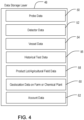
- the remote server 26 may be a computer configured as a web page host providing web-enabled services and including functional layers such as user identification management 42, a user data filter 44, a computation layer 46 and a data storage layer 48.
- the user identification management 42 may be a user authentication function to verify that authenticated users and mobile devices are properly screened and allowed access.
- the computation layer 46 may include functionality that receives raw or partially processed data from a detector 12 via a mobile device 18 and determines the type and level of contaminant associated with the received data based on predetermined algorithms.
- an advantage of real-time transmission of the detected data to the server 26 for processing is that greater processing power may be applied to more quickly translate the received data into contaminant level determinations.
- the central location of the computation layer 46 in the remotely located server 26 provides a centralized location with which to update and control the techniques used to translate the data from the various detectors 12.
- the computation layer 46 may implement artificial intelligence learning algorithms or specialized chemical, physical, or quantum mechanical expertise programs to process the real-time data into contaminant levels for immediate transmission from the server 26 to, and display on, the mobile device 18.
- the data storage layer 48 may include data on users, devices, device types, and, as discussed in greater detail below, a history of contaminant test results for both vessels used in a production process and products, such as crops or processed foods that have been in contact with the vessels or the contents of the vessels used in the production of that crop or food.
- the data storage layer may include probe data 50 for the various probes 20 that are associated with detectors 12 in the field and registered with the system.
- the probe data 50 may include information about each specific probe 20, such as the type and age of the probe (e.g. the number of tests run with the probe and the in service data of the probe).
- the probe data 50 may additionally include information on the probe's technology, including the substances testable by the probe alone or in combination with other probes, probe age calibration curves for use by the computation layer to adjust data received from the probe to account for potential effects of aging on the measurements, and probe technology interaction algorithms, for example this information may be an algorithm such as described herein to use multiple probe data received concurrently to differentiate for detection of a compound/contaminant that may not be directly discernible by a single probe.
- detector data on the detector 12 itself may be stored in the data storage layer 48 of the server 26.
- the detector data 52 may include serial number and MAC ID for the specific hardware, identification of authorized users, the location of the last use of the detector and the account ID associated with the detector 12.
- Vessel data 54 on the vessel being tested and tracked may be included in the data storage layer 48 of the server 26.
- the vessel data 54 may include the unique identifier of the vessel and the account ID of the account associated with that vessel.
- the data storage layer 48 also may include historical test data 56 received from different detectors 12 and associated with specific containers, product lots and so on.
- the historical test data 56 may include data for each test run, such as: a record that probe compatibility was confirmed for each test, the time stamps and detector values received for the test, the age of probe corrections and probe interaction factors determined for the test, and the calculated values for the contaminant or substance detected.
- historical test data 56 for each test run may include location and identification information, such as the geolocation of the detector 12 at time of test, the identifier information for the vessel, detector, user, and probe(s) 20 for that test run, and the account ID of the entity for whom the tests are being run and tracked.
- location and identification information such as the geolocation of the detector 12 at time of test, the identifier information for the vessel, detector, user, and probe(s) 20 for that test run, and the account ID of the entity for whom the tests are being run and tracked.
- the historical test data 56 may also include data 58 for the lot or agricultural field tested, such as the time stamps of the test, the lot/agricultural field bar code (or other unique identifier), the customer lot number of the food product and a test identifier number.
- the server 26 may also include the lot number, food description and or food pack universal product code (UPC) or other identifier and link that to the history of testing of the food and chemical exposure of the food that went into that lot of processed food.
- Geolocation information 60 on the farm or chemical plant at which testing has been or will be performed may also be stored in the data storage layer 48.
- the farm or chemical plant information 60 may include geofencing coordinates, such as perimeter coordinates for a field or plant, along with a description of the field or plant and the customer ID associated with that facility.
- Account data 62 may be stored in the data storage layer as well, including user IDs and associated information associated with each account that utilizes the system.
- probe types and technologies may be used in different embodiments.
- An example of a probe type that maybe used to differentiate between often difficult to differentiate compounds such as 2,4-D and dicamba may include probes that are an interferometric biosensor type, such as an a molecularly imprinted polymer (MIP) or and an antibody assay probe. These probes may be part of a detection system 10 that produces real-time readings for which the rate of change of those readings output by the probes may be measured with the disclosed detection system 10.
- MIP molecularly imprinted polymer
- the probes may each generate a diffraction or interferometric pattern and the changes in that pattern are detected and analyzed by the computation layer or locally at the mobile device 18 of the detection system 10, and are translated into a contaminant level, and not just a presence or absence of the contaminant.
- the contaminant level may be proportional to a rate of change of the diffraction pattern measured, such that an integration of the rate of change in the diffraction pattern may be used to determine concentration levels. This calculation may take place locally at the mobile device 18 or remotely at the server 26.
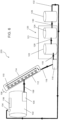
- FIG. 5 illustrates a system for the decontamination of an agricultural spray tank according to one embodiment.
- the system 100 includes at least one spray tank 102.
- the spray tank 102 may be of any size and shape as is agriculturally acceptable to spray herbicide on a crop.
- the spray tank 102 includes at least one feed pump 104 connected to a spray boom 106 by a main feed line 108.
- the feed pump 104 may be located outside of the spray tank 102 (not shown).
- the main feed line 108 may be fabricated from any material that is chemical, weather, and ozone resistant yet able to transport low pressure water-based agricultural fluids.
- the main feed line 108 is fabricated from ethylene propylene diene monomer (M-class) rubber.
- the spray pump 104 is of an acceptable size to move one or more gallons of rinsate per minute out of the tank 102 and to through the main feed line 108.
- the spray pump 104 may be powered via a battery pack (not shown) located within or external to the spray pump 104.
- the battery pack may be rechargeable and portable.
- the spray pump 104 may also be powered via a direct current from a surrounding source (such as on a tractor or generator or surrounding building).
- the spray boom 106 includes a plurality of nozzles 110 connected by a spray boom manifold 112.
- the spray boom 106 may be of any agriculturally acceptable size and include any number of nozzles 110.
- the nozzles 110 and spray manifold 112 are fabricated from any agriculturally acceptable material that may withstand the demands of spraying herbicide on crops.
- the spray boom 106 is enclosed within a rinsate collection apparatus 114.
- the rinsate collection apparatus 114 is of a size and shape to substantially or fully enclose the spray boom 106. According to an alternative embodiment, the rinsate collection apparatus 114 may partially enclose the spray boom 106. According to either embodiment, the rinsate collection apparatus 114 collects rinsate discharged from the nozzles 110 during use of the system 100.
- the rinsate collection apparatus 114 may be fabricated from any acceptable material that collects and directs rinsate.
- the rinsate collection apparatus 114 is fabricated from a solid, substantially non-flexible material that is substantially cylindrical shape such, for example, a pipe (e.g., polyvinyl chloride). According to one embodiment, the rinsate collection apparatus 114 is fabricated from a waterproof material. According to one embodiment, the rinsate collection apparatus 114 is fabricated from a flexible material. According to one embodiment, the rinsate collection apparatus 114 is fabricated to form a bag or bladder that may be unfolded or unpackaged at the time of use and dried upon completion of decontamination. According to such an embodiment, the bag or bladder may be attached to the spray boom 106 via at least one hook and loop fastener.
- the rinsate collection apparatus 114 is connected to a feed pump 116 via a first discharge line 118.
- the feed pump 116 causes rinsate from the rinsate collection apparatus 114 to move through the first discharge line 118 through the feed pump 116 and into a rinsate treatment unit 120 via a second discharge line 119.
- the feed pump 116 is of an acceptable size to move one or more gallons of rinsate per minute out of the rinsate collection apparatus 114 and to through the second discharge line 108.
- the feed pump 116 may be powered via a battery pack (now shown) located within or external to the feed pump 116.
- the battery pack may be rechargeable and portable.
- the feed pump 116 may also be powered via a direct current from a surrounding source (such as on a tractor or generator or surrounding building).
- a surrounding source such as on a tractor or generator or surrounding building.
- Each of the first and second discharge lines (118, 119) are fabricated from any material that is chemical, weather, and ozone resistant yet able to transport low pressure water-based agricultural liquids such as, for example, ethylene propylene diene monomer (M-class) rubber.
- the discharge line 119 connects the feed pump 116 to at least one filter 122 (e.g., a first filter) within the rinsate treatment unit 120.
- the rinsate treatment unit 120 further includes an optional second filter 124.
- the rinsate treatment unit 120 optionally includes a detector 126 located within the rinsate treatment unit 120.
- a first treatment line 128 connects the first filter 122 to the second filter 124.
- a second treatment line 130 connects the second filter 124 to the detector 126.
- a decontamination line 132 connects the detector 126 back to an inlet 134 (or cap 136) on the spray tank 102.
- Each of the first and second treatment lines (128, 130) and decontamination line 132 are fabricated from any material that is chemical, weather, and ozone resistant yet able to transport low pressure water-based agricultural liquids such as, for example, ethylene propylene diene monomer (M-class) rubber.
- M-class ethylene propylene diene monomer
- the entire rinsate treatment unit 120 may be portable as well as sized to be held and operated in the operator's hand.
- the rinsate treatment unit 120 may be formed of a housing unit 121 that encompasses the filter(s) (e.g., 122 and 124) and, optionally, the detector 126.
- the housing unit may be made of any acceptable material capable of enclosing and securing one or more filters (e.g., 122 and 124) and, optionally, a detector 126.
- the at least one filter 122 aids the removal or deactivation of herbicides present in the rinsate.
- the filter 122 contains activated charcoal.
- the activated charcoal is in powder form and exhibits a high affinity for organic compounds such as herbicides.
- the filter 122 contains at least one pound of activated charcoal for each 50 gallons of rinsate passed through the system.
- the filter 122 contains a fibrous form of activated carbon.
- the filter 122 contains at least one resin. Suitable resins include, but are not limited to, anion exchange resins, cation exchange resins, and softener resins.
- the optional second filter 124 further aids the removal or deactivation of herbicides present in the rinsate.
- the second filter 124 performs an ozonation process.
- the ozone is injected as small bubbles in the passing rinsate and then filtered.
- the second filter 124 includes an ultraviolet purification component.
- the ultraviolet component may be utilized alone or in addition to the ozonation process.
- the filter 124 includes an ultraviolet light source (lamp) enclosed in a protective transparent sleeve.
- the light source may be mounted such that rinsate passes through a flow chamber in the filter 124 and is exposed to the ultraviolet light rays.
- the detector 126 which may be all or part of the detector 10 of FIG. 1 , analyzes the rinsate as the rinsate passes through the detector 126. According to one embodiment, the detector 126 provides real time readings regarding herbicidal levels within the rinsate. According to one embodiment, the detector 126 confirms and provides documentation of effective cleanout based on herbicidal levels in the rinsate. Such documentation may include real-time transmission of data via email, storage on an internal or external drive, or printout. Such documentation provides evidence of herbicide removal and/or inactivation and reduces or eliminates liability on the farm operator for damaged crops caused by herbicidal treatment.
- the detector 126 may utilize gold catalyzed chemiluminescence immunoassay, immunoassay in microfluidics, electrochemical immunoassay, or dip-stick immunoassay.
- the detector 126 utilizes an interferometric sensor based on a planar optical waveguide.
- the detector 126 may utilize immunoassays on top of the waveguide for detection of one or more herbicides.
- the detector 126 may include a reference component that provides secondary confirmation that the system 100 is working properly. Such secondary confirmation may include a visual confirmation or chemical reference that is detected and measured by the detector 126.
- the detector 126 is calibrated to detect certain levels of at least one herbicide.
- the detector 126 is calibrated to detect certain levels of specific herbicides such as, for example, 2,4-D (2,4-dichlorophenoxyacetic acid) and dicamba (2-methoxy-3,6-dichlorobenzoic acid).
- specific herbicides such as, for example, 2,4-D (2,4-dichlorophenoxyacetic acid) and dicamba (2-methoxy-3,6-dichlorobenzoic acid).
- FIG. 6 illustrates a system for the decontamination of an agricultural spray tank according to an alternative embodiment.
- the system 200 includes the same components as illustrated in the embodiment of FIG. 5 .
- the detector 126 is located outside the rinsate treatment unit 120.
- the detector 126 may be portable as well as sized to be held in the operator's hand.
- FIG. 7 illustrates an embodiment of a system for the decontamination of a vessel 222.
- a tube or other conduit 226 is introduced to the vessel 222 to place a detection system 230.
- a pump 228 may be utilized with the conduit 226 to aid in moving the fluid 224 from the vessel 222 to the detection system 230.
- the vessel 222 may be an industrial/commercial mix tank or transportation vessel of any type. In the example of FIG.
- the cleaning process may be a default cleaning process (time and amount of cleaning agent pre-determined) and the measurement by the detection system 230 may be made as the rinsate from the cleaning process is drained from the vessel 22 at the end of the default cleaning process to verify in real-time the level of contaminant on-site without the need to send out a physical sample.
- the cleaning process may be accomplished using a fluid recirculation process as described for the cleaning of a spray tank on a farm in FIGS. 5-6 .
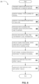
- FIG. 8 One embodiment of a method 300 for cleaning and verifying decontamination of a vessel, for example of a spray tank or similar vessel being used on a farm, using the systems described above is illustrated in FIG. 8 .
- the farmer may first enter a user identifier (ID) in the mobile device and the mobile device transmits that information to the remote server for authentication, along with automatically appending information on the detector 12, which may include probe and/or detection circuitry identifying information (at 302).
- the probe and/or detection circuitry identifying information may include serial number information for the probe 20 and detection circuitry 22, the Media Access Control (MAC) address for each and the Internet protocol (IP) network address.
- ID user identifier
- IP Internet protocol
- the spray tank may have a scannable code, such as an optically scannable bar code or QR code affixed to it that may be automatically scanned with the mobile device. Any of a number of other spray tank or other vessel identifier labelling techniques, such as radio frequency identifiers (RFIDs) and so on may be used. Alternatively, a unique serial number, code or other identifier associated with the spray tank may be manually entered into the mobile device 18 and transmitted to the remote server 26.
- RFIDs radio frequency identifiers
- the farmer may use the mobile device to scan in or manually enter one or more substance/contaminant identifiers, such as a Universal Product Code (UPC) for the one or more substances, to inform the remote server of the one or more contaminants that the sensor will be providing data on during the spray tank cleaning process (at 306).
- the mobile device 18 may also include geolocation information in its communications with the server, either from a GPS sensor included in the mobile device 18 or a GPS software function capable of generating the location of the mobile device in cooperation with a cellular or other communication network in communication with the mobile device.
- the mobile device may transmit a farm identifier entered by the user or determined by the GPS position of the mobile device.
- the cleaning process may be started, for example using a set-up such as shown in Example 1 above, where the rinsate material is cycled through the spray tank and any associated equipment and real-time data from the probe and detection circuitry of the detector are transmitted to the mobile device 18.
- the mobile device 18 transmits the real-time data to the server and the server 26 processes the data in real-time to account for the age of the probe and probe type to determine contaminant levels (at 308).
- the ongoing contaminant level measurements may be transmitted back to the mobile device 18 and displayed by the mobile device 18 to the farmer or other user (at 310).
- the server 26 may transmit a completion signal to the mobile device 18 that may be displayed to the farmer (at 312) and prompts the farmer to then shut-off the cleaning process (314).
- the mobile device 18 or server 26 may then associate the sprayed field ID with the spray tank ID (at 316), as well as associate the crop specific data, such as lot ID and type, with the spray tank ID (at 318) in the historical test data record of the data storage layer in the server.
- the mobile device may calculate and display the contamination level information and generate the completion signal internally.
- the mobile device may still perform the steps of authenticating user ID, detector information, vessel identification and contaminant identification with the remote server 26 (steps 302, 304 and 306), but instead of then sending the raw sensed contaminant data to the server 26, the mobile device may internally identify and determine the contaminant level from the raw sensor data without transmitting it to the server 26.
- the algorithms for identifying contaminant level, for adjusting calculation based on probe or other detector information and for recognizing the point (e.g. a predetermined contaminant level threshold or predetermined contaminant level range) when a desired contaminant level has been reached may all be completed and generated at the mobile device itself.
- the memory of the mobile device may be preloaded with instructions for making the analysis, or the server 26 may transmit to the mobile device the instructions and other information for the mobile device to locally process the data in response to receiving the authentication and device identification information from the mobile device (steps 302-306).
- the mobile device 18, may send a signal preventing operation of the cleaning process equipment, such as the pumps that flush rinsate through the spray tank and spray arm described in Example 1 above, if there is a mismatch or other irregularity in the authentication information (user ID, geolocation information, etc.) provided to the server with the information contained in the server. For example, if the server determines from the contaminant identifying information and the probe or other sensor identifying information that the probe 20 (or probes) is not suited to test for the contaminant, then the server may send a signal notifying the user not to start the process.
- the cleaning process equipment such as the pumps that flush rinsate through the spray tank and spray arm described in Example 1 above
- the server may send a command or instructions to the mobile device that is relayed to the cleaning equipment, to shut-off a power switch or other lockout device of the cleaning equipment to prevent the cleaning process from starting or continuing.
- the mobile device 18 may receive the authentication or compatibility error from the server and determine locally to generate and send the power shut down command to the cleaning equipment.
- this automatic control of the cleaning process may be applied when a cleaning process has already started.
- this same power shut down code capability may be used, where the completion signal of step 14 is either accompanied by a command to be forward by the mobile device to shut down the cleaning process, or by instructions for the mobile device to generate its own shut-down command to automatically stop the cleaning process, rather than simply waiting for the farmer to shut down the equipment after receiving the displayed completion notification.
- the detection system 10, or at least the mobile device 18 of the system 10 may be interlocked with equipment to shut down any equipment involved in any portion of the overall process of managing the flow of chemicals and food, not just at the farm level or limited to shutting down the cleaning process automatically as described above.
- the interlock-enabled system and process consists of the detection system 10, for example the mobile device 18 of the detection system 10, having a suitable electromagnetic radiation (EMR) transmitter, for example radio frequency, RFID, Wi-Fi, Bluetooth, cellular or optical technologies.
- EMR electromagnetic radiation
- the mobile device 18 may be a smartphone, tablet or other portable device having a display 350, user input interface 352, processor 354, GPS location function or sensor 355, memory 356 and one or more EMR transmitters 358.
- the equipment that mobile device 18 would be able to control based on the contaminant detection results may include the entirety or a part of a vessel cleaning apparatus 360 (e.g. the cleaning equipment on the farm used to clean the vessel as described above), a food processing device 362 at a food processing location, farm equipment 364 (such as a sprayer, tractor or other farm implement) at a farm, or any of a number of other pieces of equipment involved in the processing or movement of a chemical or food product near the mobile device 18.
- Any piece of equipment 360, 362, 364 controllable by the mobile device may include, either integrated in its circuitry or as a discrete add-on component, an EMR receiver 366 compatible with the EMR transmitter 358, and an EMR-activated relay 368.
- the mobile device 18 of the detector system 10 may be programmed in memory 356 to send an EMR signal when sample results are within the specified range as determined locally or by the remote server.
- the EMR signal may be a direct wireless communication link 370 between mobile device and equipment 360, 362, 364 as illustrated, or may be via a communication path over one or more networks in communication with the equipment 360, 362, 364 and mobile device 18. Because the EMR receiver 366 is preferably linked to a relay 368 that controls the power to activate the connected equipment upon receipt of the signal, automated control of the particular equipment by the detection system 10 may be achieved.
- the equipment that can be included in interlocked mode with the detection system may include shut-off valves, pumps, power control units, motors (tractors, farm equipment, conveyor belts, fork-lifts, etc.) and a variety of off/on switches available for industrial processes.
- the mobile device 18 would only be able to control the particular piece of equipment 360, 362, 364 located in geographical proximity to the mobile device based on the testing or authentication taking place at the processing stage where the user and mobile device are located.
- the various different pieces of equipment 360. 362, 364 illustrated in FIG. 9 are representative of the types of equipment the automated shut-down or lockout process may be applied and does not represent that all of these pieces of equipment must either be at the same geographical location or be simultaneously controllable by the shut-off command transmitted by a single mobile device.
- the more than one piece of equipment, or more than one part of a single piece of equipment may be independently and concurrently controlled by remote commands from the mobile device 18.
- the sprayer device may include multiple sets of EMR receivers 366 and associated EMR activated relays 368, each controlling a different function of the sprayer device.
- the detection system 10 may control an EMR receiver and EMR activated relay associated with a pump on the sprayer to shut-off that pump and stop a cleaning process of a vessel on the sprayer in response to detecting that the contaminant of interest is at an acceptable level, while concurrently controlling another part of the sprayer, such as a valve connecting the vessel to the spray nozzles of the sprayer, to prevent any spraying operation of the sprayer until the contaminant of interest is at the acceptable level.
- both a shutdown of a cleaning process and a removal or initiation of a lockdown of the normal operation of the equipment may be controlled by signals automatically generated by the detection system 10 or passed on by the detection system from the server 26.
- only the lockdown function to prevent of the equipment's normal function may be automatically controlled and the shut-off of the cleaning process may be accomplished manually upon receipt and display to the user of the completion notification as described above.
- a management override function is contemplated to release or reset the systems affected by a shutdown.
- interlock (lockdown) activation when a contaminant level is too high may also trigger the detector system 10 to record the time and GPS location of the initiation and termination of signals for the shutdown.
- the mobile device 18 may store this locally in memory 356 and/or transmit this information to the remote server 26.
- the mobile device 18 may also concurrently generate and transmit a notification of the interlock activation to a management device or devices.
- the notification may be an automatically generated call, text, email or other communication and may include the time and location of the shutdown, as well as details on the user and specific equipment affected. If in reply an authorized management signal is subsequently received at the mobile device 18, the shutdown equipment may be released from the interlock shutdown command and resume operation.
- An advantage of the mobile device 18 and portable detector 12 is that they can be used on location to send real-time data from the probe or probes to a remote server for interpretation in real-time.
- the real-time data from the probe(s) may be interpreted and processed locally at the mobile device to provide contaminant level information, rather than sending the data to the server for calculation of the contaminant levels.
- This real-time detection and local processing, or transmission and remote processing, of data during the cleaning process avoids the typical physical sample acquisition time and delay before next use of the spray tank or other vessel while the sample is sent to a lab.
- the farmer or user of the system may be able to use the real-time detection and certification of contaminant level to shut off the cleaning process at a point much earlier than a default process might require.
- This on-site detection and verification may also avoid the need to re-clean a tank or vessel that was cleaned with a default cleaning process but later received results from the physical sample that indicated more cleaning was necessary.
- an automated shut-off command may provide an even greater process improvement.
- the farm equipment such as a tractor or sprayer vehicle, includes a lockdown device that is capable of preventing or shutting down power to the vehicle, or at least power to the portion of the vehicle capable of distributing the contents of the vessel, if the vehicle attempts to use uncleaned, or improperly cleaned vessel.
- the probe 20 and detector circuitry 22 of a portable detector 12 that may be used in the detection system 10 described herein may be configured for measuring the presence of one or of multiple different chemicals/contaminants.
- An advantage of the detection system 10 and remote server 26 processing of real-time contaminant measurements is that certain substances, for example herbicides 2,4-D and dicamba can be difficult to differentiate with single sensors. Due to the ability of the detection system to detect and transmit information in real-time, difficult to distinguish substances such as these may be more successfully differentiated.
- Signals from different probes may be combined in the present system to allow the computation layer of the server to interpret the signals in real-time using a comparison algorithm based on pre-determined operating characteristics of the particular probe or probe technology: TABLE 1 Chemical Probe 1 Probe 2 2,4-D Strong Strong Dicamba Weak Strong where the presence of a strong signal on both probes (each probe using a different technology) in a side-by-side real-time comparison allows the algorithm to identify 2, 4-D rather than dicamba, when a single reading from a probe like Probe 1 or Probe 2 in the above Table 1 would not be able to make the distinction. Other side-by-side comparisons of real-time signals from different probes allow differentiation of other chemicals that may typically be difficulty to detect otherwise.
- one probe is a molecularly imprinted polymer (MIP) type that can recognize two compounds in a certain compound family but not differentiate compounds within that compound family is used in conjunction with a more precise probe, such as an antibody-based probe that responds to a specific one of those two compounds in the compound family but not the other, than the algorithm may simply be a subtraction of the two probe outputs to determine the presence of the other of the two compounds.
- MIP molecularly imprinted polymer
- FIG. 10 represents a flow of food production from field to home, with tracking the food safety for a particular food product from production to the table.
- the first stage of the food production flow of FIG. 10 includes a production plant 402 where a chemical, such as a pesticide, is produced and introduced into the food production path.
- the second stage includes a farm 404 at which food is grown that uses the pesticide from the production plant 402.
- the third stage is a food processing facility 406 that receives the food harvested from the farm 404 and either prepares the harvested food for sale as unprocessed food 412 (e.g. whole apples) or prepares some form of processed food 414 (e.g. applesauce, apple pie) from the harvested food.
- the store 408 and the home 410 are represented as the final two stages of the food production flow 400.
- the overall food production flow with safety management that is illustrated in FIG. 10 is just one of many contemplated flows and greater or fewer stages may also be utilized in other implementations when tracking a product and contaminant levels.
- Each of the stages in FIG. 10 may utilize the contaminant testing and tracking technique described above and utilize its own mobile device 18 and detector unit 12 to sample and receive real-time information on contaminant levels at each respective stage of the food production flow.
- a single central contaminant tracking service represented in FIG. 1 as the server 26, may process and store information received from the different contaminant detection systems 10 at each stage (402, 404, 406, 408, 410) for multiple different entities.
- each stage may utilize a different detection system 10 (mobile device 18 and detector 12) suited for the specific type/level/granularity of contaminant measurement desired.
- All of the different detection systems 10 used may communicate over the one or more networks 24 between the respective system and the central server 26 that tracks the path of the chemical containing vessels and the product(s) exposed to the vessel contents, in the historical test data records section 56 in the data storage layer 48 of the server 26. In this manner, specific crop may be tracked, along with the chemicals and chemical containers that came into contact with it, and certified as satisfying a predetermined contaminant exposure level with accuracy and confidence.
- each stage of the production process in FIG. 10 may include the use of a separate detection system 10, the detection systems are not reproduced in FIG. 10 for ease of illustration.
- a process of using a system such as shown in FIG. 1 to certify the chemical supply chain of a chemical to be used with a crop is described.
- a user of the mobile device 18 first enters a user identification ID.
- the mobile device also automatically transmits location and time stamp data for the mobile device and the hardware information relating to the detector unit 12 associated with the mobile device 18.
- the mobile device includes global positioning system (GPS) capability, for example via a standalone GPS sensor in the mobile device 18 or through use of GPS functionality available through a cellular network in communication with the mobile device.
- GPS global positioning system
- the mobile device 18 passes on this data via a wireless or wired network 24 to the tracking server 26.
- the server verifies the user ID and matches the detector unit information to verify the capabilities of the probe and sensor circuitry in the detector unit.
- the detection system 10 in use at the production plant 402 may be used to verify the purity, in other words that the chemical product being produced is at a high enough concentration to indicate what is being produced is what is expected, and record the content of that tank with the server. After production of a batch of the chemical is finished and the tank is cleaned, the same detection system may then be used to detect that the production vessel is properly cleaned to a low enough level of that chemical before being used for another production process.
- the finished goods 424 from the production vessel 418 are processed through tasks A-D to track the path of the chemicals through production and prevent shipment if a contaminant is detected.
- a production plant geofence 426 may be used in conjunction with the GPS location capabilities of the mobile devices 18 used in the detection systems 10 to verify that the chemical products are at the chemical plant 402.
- the mobile device 18 of the detection system 10 located at the farm 404 scans in the incoming finished chemical goods (e.g. herbicide) and the previously established farm geofence 428 provides verification at the server that the expected chemicals 424 are received at the correct location, where they may be scanned and checked for contaminants.
- finished chemical goods e.g. herbicide
- the chemical products may be used in a spray tank 430, where the spray tank 430 is tested, before and after use, as described previously.
- the lockout function at the farm 404 may be implemented as a shutdown of the sprayer and or the tractor carrying the sprayer if the sprayer is not cleaned or contains an undesirable contaminant based on the detector system measurements taken on site (tasks A, B and D).
- the farm stage also includes the creation of a new bar code or other identifier (task C) at harvest to link the harvested food to the specific chemicals used, the farm location and the testing history of the one or more vessels used in the process of growing and harvesting the food.
- Additional chemical exposure data may be provided to the system 100 at the farm stage 404 by one or more drift detectors 432 that can be located just inside or outside the field boundary (geofence) to determine if adjacent field herbicide or other chemical application drifted into the area of the crop being harvested.
- the location of the drift detector 432, the time of the measurements and the crop or lot identifier may be linked in the historical test data 56 of the server 26 based on a query to the drift detector 432 by a mobile device 18 that is in communication with the server 26.
- the geofence 426 at the production plant or the geofence 428 at the farm may each be a plurality of separately identifiable geofences (previously determined and provided to the detection system 10 or server 26) that divide up the production facility or farm into separately identifiable sections.
- the farm may include separate geofences for each different field so the location of equipment and chemicals can be tracked on a field-by-field basis. In this manner, a farmer will be able to specify that sprayer equipment, such as a spray rig, with the current chemicals is compatible for fields 1,2 and 3 but not field 4, 5 and 6 until the spray rig has been certified as clean.
- the detection system 10 could either be configured to maintain a lockdown of the spraying operation capabilities of the spray rig for anywhere in the overall farm geofence until the vessel and/or other components of the spray rig are cleaned, or may be configured to lockdown the spraying operations of the spray rig on only predesignated fields within the farm until the spray rig is certified as cleaned.
- the lot or lots of harvested foods may be shipped to a food processing facility 46 as a next stage.
- the harvested lots may be lightly processed, such as basic washing and packing of fruits or vegetable, or may be prepared in a more processed form, such as a sauce or other prepared version of the harvested food.
- each item or package is barcode detected, tested for contaminants, given a new barcode that is linked to the history of the prior one and, subject to a processing interlock feature (e.g. automatically signaling equipment at the food processing facility 406 to shut down, such as by shutting down a conveyor or preventing automated movement or shipment of a lot that fails a contaminant test (see task A-D).
- a processing interlock feature e.g. automatically signaling equipment at the food processing facility 406 to shut down, such as by shutting down a conveyor or preventing automated movement or shipment of a lot that fails a contaminant test (see task A-D).
- a detection system 10 that may be used at the processing facility 406 may be configured with appropriate probes to sample wash water used to rinse the fruits or vegetables and/or headspace gasses given off by the fruits or vegetables, for example.
- a detection system 10 may also be used to check and record location data for the processed or unprocessed food, as well as to perform some testing for contaminants.
- the store and home tests may include testing wash water and or headspace gasses.
- the server may communicate with one or more of a regulatory server 28, insurance company server, food industry server or other authorized system to provide verification of measurements and procedures that the food has gone through.
- the communication may be in the form a token or other data structure at, which may be encrypted with a shared key for improved trust and validity, certifying that levels of toxins or contaminants measured fall within a predetermined range.
- These certifications or tokens may be locally stored at the server 26 upon receipt from the regulatory server or other certification source and accessible to stores and to consumers at their homes, by scanning the barcode or other identifier on the processed or unprocessed food, to bolster confidence in the quality level of the food.
- certifications may be automatically transmitted by the server 26 to an insurer, association, cooperative or other interested and authorized party in response to a predefined milestone in processing of the food or chemical.
- any available certification token, and/or the historical data for the product (or chemical or vessel) may be triggered for transmission by the server in response to receipt at the server of a location change for the tracked food, chemical or vessel (chemical production facility to farm, farm to food processing facility and/or food processing facility to store transitions).
- the location change may be triggered by barcode scanning and geolocation data of the scanning device, such as a detection system 10, that reaches the server.
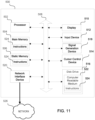
- an illustrative embodiment of a general computer system that may be used in, or for, one or more of the components described above, or in any other system configured to carry out the methods discussed above, is shown and is designated 500.
- the computer system 500 can include a set of instructions that can be executed to cause the computer system 500 to perform any one or more of the methods or computer-based functions disclosed herein.
- the computer system 500 may be mobile or non-mobile, operate as a stand-alone device, or may be connected using a network, to other computer systems or peripheral devices.
- the computer system may operate in the capacity of a server or as a client user computer in a server-client user network environment, or as a peer computer system in a peer-to-peer (or distributed) network environment.
- the computer system 500 can also be implemented as, or incorporated into, various devices, such as a personal computer ("PC"), a tablet PC, a set-top box (“STB”), a personal digital assistant ("PDA”), a mobile device such as a smart phone or tablet, a palmtop computer, a laptop computer, a desktop computer, a network router, switch or bridge, or any other machine capable of executing a set of instructions (sequential or otherwise) that specify actions to be taken by that machine.
- PC personal computer
- PDA personal digital assistant
- the computer system 500 can be implemented using electronic devices that provide voice, video or data communication.
- the term "system” shall also be taken to include any collection of systems or sub-systems that individually or jointly execute a set, or multiple sets, of instructions to perform one or more computer functions.
- the computer system 500 may include a processor 502, such as a central processing unit (“CPU”), a graphics processing unit (“GPU”), or both. Moreover, the computer system 500 can include a main memory 504 and a static memory 506 that can communicate with each other via a bus 508. As shown, the computer system 500 may further include a video display unit 510, such as a liquid crystal display (“LCD”), an organic light emitting diode (“OLED”), a flat panel display, a solid state display, or a cathode ray tube (“CRT").
- LCD liquid crystal display
- OLED organic light emitting diode
- CRT cathode ray tube
- the computer system 500 may include one or more input devices 512, such as a keyboard, scanner, digital camera or audio input device, and a cursor control device 514, such as a mouse.
- the computer system 500 can also include a memory unit 516, which may be a solid state or a disk drive memory, a signal generation device 518, such as a speaker or remote control, and a network interface device 520.
- the memory unit 516 may include a computer-readable medium 522 in which one or more sets of instructions 524, such as software, can be embedded. Further, the instructions 524 may embody one or more of the methods or logic as described herein. In a particular embodiment, the instructions 524 may reside completely, or at least partially, within the main memory 504, the static memory 506, and/or within the processor 502 during execution by the computer system 500. The main memory 504 and the processor 502 also may include computer-readable media.
- dedicated hardware implementations including application specific integrated circuits, programmable logic arrays and other hardware devices, can be constructed to implement one or more of the methods described herein.
- Applications that may include the apparatus and systems of various embodiments can broadly include a variety of electronic and computer systems.
- One or more embodiments described herein may implement functions using two or more specific interconnected hardware modules or devices with related control and data signals that can be communicated between and through the modules, or as portions of an application-specific integrated circuit. Accordingly, the present system encompasses software, firmware, and hardware implementations.
- the methods described herein may be implemented by software programs executable by a computer system.
- implementations can include distributed processing, component/object distributed processing, and parallel processing.
- virtual computer system processing can be constructed to implement one or more of the methods or functionality as described herein.
- the present disclosure contemplates a computer-readable medium that includes instructions 524 or receives and executes instructions 524 responsive to a propagated signal; so that a device connected to a network 526 can communicate voice, video or data over the network 526. Further, the instructions 524 may be transmitted or received over the network 526 via the network interface device 520.
- While the computer-readable medium is shown to be a single medium, the term “computer-readable medium” includes a single medium or multiple media, such as a centralized or distributed database, and/or associated caches and servers that store one or more sets of instructions.
- the term “computer-readable medium” shall also include any tangible medium that is capable of storing, encoding or carrying a set of instructions for execution by a processor or that cause a computer system to perform any one or more of the methods or operations disclosed herein.
- the computer-readable medium can include a solid-state memory such as a memory card or other package that houses one or more non-volatile read-only memories, such as flash memory. Further, the computer-readable medium can be a random access memory or other volatile re-writable memory. Additionally, the computer-readable medium can include a magneto-optical or optical medium, such as a disk or tapes or other storage device to capture information communicated over a transmission medium. A digital file attachment to an e-mail or other self-contained information archive or set of archives may be considered a distribution medium that is equivalent to a tangible storage medium. Accordingly, the disclosure is considered to include any one or more of a computer-readable medium or a distribution medium and other equivalents and successor media, in which data or instructions may be stored.
Landscapes
- Engineering & Computer Science (AREA)
- Chemical & Material Sciences (AREA)
- Health & Medical Sciences (AREA)
- Life Sciences & Earth Sciences (AREA)
- Physics & Mathematics (AREA)
- General Physics & Mathematics (AREA)
- General Health & Medical Sciences (AREA)
- Pathology (AREA)
- Analytical Chemistry (AREA)
- Biochemistry (AREA)
- Food Science & Technology (AREA)
- Medicinal Chemistry (AREA)
- Immunology (AREA)
- Combustion & Propulsion (AREA)
- Software Systems (AREA)
- Theoretical Computer Science (AREA)
- Multimedia (AREA)
- General Engineering & Computer Science (AREA)
- Mechanical Engineering (AREA)
- Sampling And Sample Adjustment (AREA)
- Apparatus For Disinfection Or Sterilisation (AREA)
Claims (15)
- Système de détection de contaminant chimique (10) comprenant :un détecteur portable (12) comportant une sonde (20) et un ensemble de circuits de détecteur (22) en vue de la détection d'un contaminant prédéfini dans un échantillon de fluide ; etun dispositif mobile (18) configuré pour :
recevoir sans fil des données de détection de contaminant en provenance du détecteur portable et transmettre les données de détection de contaminant en provenance du détecteur portable à un processeur situé à distance en temps réel ; caractérisé en ce que le dispositif mobile (18) est en outre configuré pour :recevoir et afficher sur le dispositif mobile des données de niveau de contaminant en temps réel traitées par le processeur situé à distance à partir des données de détection de contaminant, et en ce quele détecteur portable utilise un capteur interférométrique basé sur un guide d'ondes optique plan. - Système de détection de contaminant chimique de la revendication 1,
ledit système étant mobile et dimensionné pour être portatif, et éventuellement ledit dispositif mobile étant choisi dans le groupe constitué d'un téléphone intelligent, d'une tablette et d'un ordinateur portable. - Système de détection de contaminant chimique de la revendication 1, ledit détecteur portable comprenant une pluralité de sondes, chacune des sondes étant configurée pour détecter un contaminant différent.
- Utilisation du système de détection de contaminant chimique de la revendication 1 dans un processus de nettoyage, ledit détecteur portable recevant l'échantillon de fluide en provenance d'un appareil de collecte d'effluents (16) raccordé à un récipient pour contenir un fluide, durant un processus de nettoyage du récipient.
- Utilisation du système de détection de contaminant chimique de la revendication 4, ledit dispositif mobile recevant et affichant une notification de fin de nettoyage reçue en provenance du processeur à distance en réponse à la détermination par le processeur à distance que les données de contaminant transmises indiquent qu'un niveau de contaminant dans l'échantillon de fluide a atteint un niveau prédéfini.
- Utilisation du système de détection de contaminant chimique de la revendication 5, ledit dispositif mobile, en réponse à la réception de la notification de fin de nettoyage, transmettant automatiquement une instruction d'arrêt à l'équipement de nettoyage en cours d'utilisation dans le processus de nettoyage du récipient ;
éventuellement, après la transmission de l'instruction d'arrêt, ledit dispositif mobile transmettant un identifiant de ferme et un identifiant de culture au processeur situé à distance pour l'association d'une ferme et d'une culture avec le récipient au niveau du serveur à distance. - Système de détection de contaminant chimique de la revendication 2, un parmi : le dispositif mobile étant en outre configuré pour, en réponse à la réception de données de niveau de contaminant en temps réel traitées par le processeur à distance à partir des données de détection de contaminant, dans une plage de niveaux de contaminant prédéfinie, transmettre automatiquement une instruction d'arrêt à un équipement de traitement en communication avec le dispositif mobile ;
ledit dispositif mobile étant sélectionné dans le groupe constitué d'un téléphone intelligent, d'une tablette et d'un ordinateur portable. - Système de détection de contaminant chimique de la revendication 3, un dispositif mobile étant configuré pour :recevoir sans fil des données de détection de contaminant en provenance du détecteur portable pour chacune de la pluralité de sondes et transmettre les données de détection de contaminant à partir du détecteur portable à un processeur situé à distance en temps réel ;recevoir et afficher sur le dispositif mobile des données de niveau de contaminant en temps réel pour chacun d'une pluralité de contaminants différents déterminés par le processeur à distance à partir des données de détection de contaminant pour la pluralité de sondes.
- Procédé de détermination du niveau de contaminant chimique dans un échantillon de fluide, le procédé comprenant les étapes de :introduction d'une sonde d'un système détecteur portable (10) dans un échantillon de fluide, ladite sonde (20) étant configurée pour détecter au moins un contaminant dans l'échantillon de fluide ;transmission sans fil des signaux de détection de contaminant à partir de l'ensemble de circuits de détection (22) en communication avec la sonde vers un dispositif mobile (18) du système détecteur portable ;transmission, en temps réel, des signaux de détection de contaminant du dispositif mobile à un système de traitement situé à distance ;réception, en réponse aux signaux de détection de contaminant transmis, des données de niveau de contaminant en temps réel traitées par le système de traitement localisé à partir des signaux de détection de contaminant ; etaffichage des données de niveau de contaminant en temps réel à un utilisateur sur un afficheur du dispositif mobile,ledit détecteur portable utilisant un capteur interférométrique basé sur un guide d'ondes optique plan.
- Procédé de la revendication 9, un parmi :l'échantillon de fluide étant prélevé dans un réservoir de solution à pulvériser agricole situé dans une ferme ; ledit échantillon de fluide étant prélevé dans une cuve de mélange industriel ou une cuve de transport ;ledit échantillon de fluide étant prélevé durant la transformation des aliments dans une installation de transformation des aliments.
- Procédé de la revendication 9, ledit système détecteur portable comprenant une pluralité de sondes, chacune des sondes étant configurée pour détecter un contaminant différent ; et
ledit procédé comprenant en outre la transmission simultanée de signaux de détection de contaminant à partir de l'ensemble de circuits de détection en communication avec chacune de la pluralité de sondes au dispositif mobile du système détecteur portable. - Procédé selon la revendication 9, ladite introduction de la sonde du système détecteur portable dans l'échantillon de fluide comprenant l'introduction de la sonde dans l'effluent à partir d'un appareil de collecte d'effluent raccordé à un récipient durant un processus de nettoyage dans une ferme.
- Procédé de la revendication 12, comprenant en outre la réception d'une notification de fin de nettoyage en provenance du processeur à distance en réponse à la détermination par le processeur à distance que les signaux de détection transmis indiquent qu'un niveau de contaminant dans l'échantillon de fluide a atteint un niveau acceptable prédéfini ;
éventuellement comprenant en outre le dispositif mobile, en réponse au message de fin de nettoyage, transmettant une commande d'arrêt configurée pour arrêter automatiquement l'équipement en cours d'utilisation dans le processus de nettoyage du récipient. - Procédé permettant la gestion de données de certification de contaminant sur la base d'essais en temps réel de contaminants à des étapes locales de production d'un produit, le procédé comprenant :
dans un système comportant une pluralité d'installations de manipulation de produits au niveau de différents emplacements géographiques, chacun d'une pluralité de systèmes de détection de contaminant portables (10) situés au niveau de l'une respective parmi les installations de manipulation de produits étant en communication avec un serveur central de suivi de contaminant, le serveur central de suivi de contaminant :recevant sans fil une identification d'utilisateur et de dispositif en provenance d'un système de détection de contaminant portable au niveau de l'une de la pluralité d'installations de manipulation de produits ;recevant sans fil des données de détection de contaminant en temps réel en provenance du système de détection de contaminant portable ;déterminant un type de contaminant et des données de niveau de contaminant actuel à partir des données de détection de contaminant reçues ;transmettant les données de niveau de contaminant actuel au système de détection de contaminant portable pour les afficher au niveau du système de détection de contaminant portable, ladite détermination du type de contaminant et ladite transmission des données de niveau de contaminant actuel étant effectuées en temps réel ; eten réponse à la détermination que le niveau de contamination actuel a atteint un seuil souhaité, transmettant une notification de fin au système de détection de contaminant portable ;et communiquant une certification de niveau de confinement chimique acceptable au système de confinement portable,ledit système de détection de contaminant portable utilisant un capteur interférométrique basé sur un guide d'ondes optique plan. - Procédé de la revendication 14, ledit serveur central de suivi de contaminant transmettant une notification de fin au système de détection de contaminant portable comprenant :
la transmission d'instructions au système de détection de contaminant portable configuré pour amener le système de détection de contaminant portable à envoyer une commande d'arrêt à l'équipement au niveau de l'une de la pluralité d'installations de manipulation de produits pour arrêter une opération de nettoyage.
Applications Claiming Priority (2)
| Application Number | Priority Date | Filing Date | Title |
|---|---|---|---|
| US201862690368P | 2018-06-27 | 2018-06-27 | |
| PCT/US2019/039498 WO2020006228A2 (fr) | 2018-06-27 | 2019-06-27 | Système et procédé de détection de contamination chimique et de certification de décontamination |
Publications (4)
| Publication Number | Publication Date |
|---|---|
| EP3814757A2 EP3814757A2 (fr) | 2021-05-05 |
| EP3814757A4 EP3814757A4 (fr) | 2022-03-02 |
| EP3814757C0 EP3814757C0 (fr) | 2024-06-12 |
| EP3814757B1 true EP3814757B1 (fr) | 2024-06-12 |
Family
ID=68985061
Family Applications (1)
| Application Number | Title | Priority Date | Filing Date |
|---|---|---|---|
| EP19827329.4A Active EP3814757B1 (fr) | 2018-06-27 | 2019-06-27 | Système et procédé de détection de contamination chimique et de certification de décontamination |
Country Status (6)
| Country | Link |
|---|---|
| US (2) | US11300553B2 (fr) |
| EP (1) | EP3814757B1 (fr) |
| CA (1) | CA3098886A1 (fr) |
| ES (1) | ES2982589T3 (fr) |
| MX (1) | MX2020012099A (fr) |
| WO (1) | WO2020006228A2 (fr) |
Families Citing this family (9)
| Publication number | Priority date | Publication date | Assignee | Title |
|---|---|---|---|---|
| CA3171968A1 (fr) * | 2020-03-27 | 2021-09-30 | Salvus, Llc | Systeme et procede de surveillance d'analytes et modelisation predictive |
| CN115516306B (zh) * | 2020-05-08 | 2026-04-17 | 安捷伦科技有限公司 | 用于感测顶空小瓶存在的方法和系统 |
| US11353381B1 (en) * | 2020-06-09 | 2022-06-07 | Applied Materials, Inc. | Portable disc to measure chemical gas contaminants within semiconductor equipment and clean room |
| US12399172B2 (en) | 2020-09-18 | 2025-08-26 | Salvus, Llc | Interferometric detection and quantification system and methods of use in healthcare |
| US11994504B2 (en) | 2020-09-18 | 2024-05-28 | Salvus, Llc | Interferometric detection and quantification system and methods of use in food processing and food supply chain |
| US11740177B2 (en) | 2020-09-18 | 2023-08-29 | Salvus, Llc | Interferometric detection and quantification system and methods of use in aquatics |
| US12613187B2 (en) * | 2020-09-18 | 2026-04-28 | Salvus, Llc | Interferometric detection and quantification system and methods of use in chemical processing |
| DE102021107256B4 (de) * | 2021-03-23 | 2024-02-22 | digid GmbH | Digitales Analysesystem |
| CN120984421B (zh) * | 2025-10-24 | 2026-01-06 | 陕西秦达商用车辆制造有限公司 | 腻子打磨室粉尘回收与表面清洁系统及方法 |
Citations (1)
| Publication number | Priority date | Publication date | Assignee | Title |
|---|---|---|---|---|
| WO2018057647A1 (fr) * | 2016-09-23 | 2018-03-29 | Alveo Technologies, Inc. | Méthodes et compositions de détection d'anévrismes |
Family Cites Families (14)
| Publication number | Priority date | Publication date | Assignee | Title |
|---|---|---|---|---|
| DE69226654T2 (de) * | 1991-02-15 | 1999-04-15 | Formulogics, Inc., Trenton, N.J. | Bestimmung von verunreinigungen |
| US6207460B1 (en) * | 1999-01-14 | 2001-03-27 | Extraction Systems, Inc. | Detection of base contaminants in gas samples |
| KR100439737B1 (ko) * | 2001-11-30 | 2004-07-12 | 한국과학기술연구원 | 미량 산성농약의 동시 검출법 |
| US7452507B2 (en) | 2002-08-02 | 2008-11-18 | Sandia Corporation | Portable apparatus for separating sample and detecting target analytes |
| US20070100666A1 (en) * | 2002-08-22 | 2007-05-03 | Stivoric John M | Devices and systems for contextual and physiological-based detection, monitoring, reporting, entertainment, and control of other devices |
| US7019637B1 (en) | 2003-03-28 | 2006-03-28 | Sandia National Laboratories | Systems and methods for detecting and processing |
| JP2004356356A (ja) * | 2003-05-29 | 2004-12-16 | Oki Electric Ind Co Ltd | 洗浄終了判定方法および洗浄装置 |
| US20050199267A1 (en) * | 2004-03-15 | 2005-09-15 | Oakes Kenton T. | Washing system using recycled cleaning liquid |
| US20100015601A1 (en) | 2004-11-24 | 2010-01-21 | Invitrogen Corporation | Biological confirmation and detection system |
| US7905154B2 (en) | 2004-11-29 | 2011-03-15 | Jones Jr Arthur T | Apparatus and method of contaminant detection for food industry |
| US8388904B1 (en) | 2008-12-22 | 2013-03-05 | Reactive Surfaces, Ltd., Llp | Equipment decontamination system and method |
| US9212996B2 (en) | 2013-08-05 | 2015-12-15 | Tellspec, Inc. | Analyzing and correlating spectra, identifying samples and their ingredients, and displaying related personalized information |
| CN103675225A (zh) * | 2013-12-02 | 2014-03-26 | 华东理工大学 | 便携式水质检测仪及其水质检测方法 |
| CA2967022A1 (fr) | 2014-11-07 | 2016-05-12 | Proteosense | Dispositifs, systemes et procedes pour detecter des analytes |
-
2019
- 2019-06-27 EP EP19827329.4A patent/EP3814757B1/fr active Active
- 2019-06-27 ES ES19827329T patent/ES2982589T3/es active Active
- 2019-06-27 MX MX2020012099A patent/MX2020012099A/es unknown
- 2019-06-27 US US16/454,789 patent/US11300553B2/en active Active
- 2019-06-27 WO PCT/US2019/039498 patent/WO2020006228A2/fr not_active Ceased
- 2019-06-27 CA CA3098886A patent/CA3098886A1/fr active Pending
-
2022
- 2022-03-31 US US17/709,756 patent/US12571788B2/en active Active
Patent Citations (1)
| Publication number | Priority date | Publication date | Assignee | Title |
|---|---|---|---|---|
| WO2018057647A1 (fr) * | 2016-09-23 | 2018-03-29 | Alveo Technologies, Inc. | Méthodes et compositions de détection d'anévrismes |
Non-Patent Citations (1)
| Title |
|---|
| CAMPBELL DANIEL P. ET AL: "Groundwater monitoring of VOCs with an interferometric optical waveguide sensor", PROCEEDINGS OF SPIE, vol. 5586, 7 December 2004 (2004-12-07), pages 136, XP093119506, ISSN: 0277-786X, DOI: 10.1117/12.571391 * |
Also Published As
| Publication number | Publication date |
|---|---|
| US11300553B2 (en) | 2022-04-12 |
| US12571788B2 (en) | 2026-03-10 |
| ES2982589T3 (es) | 2024-10-16 |
| US20220221438A1 (en) | 2022-07-14 |
| WO2020006228A2 (fr) | 2020-01-02 |
| EP3814757C0 (fr) | 2024-06-12 |
| EP3814757A2 (fr) | 2021-05-05 |
| CA3098886A1 (fr) | 2020-01-02 |
| EP3814757A4 (fr) | 2022-03-02 |
| US20200003746A1 (en) | 2020-01-02 |
| WO2020006228A3 (fr) | 2020-07-23 |
| MX2020012099A (es) | 2021-02-16 |
Similar Documents
| Publication | Publication Date | Title |
|---|---|---|
| US12571788B2 (en) | System and method for chemical contamination detection and decontamination certification | |
| US10915861B2 (en) | Supply chain management using mobile devices | |
| US10212877B2 (en) | Seed treatment facilities, methods, and apparatus | |
| JP7362483B2 (ja) | 有害生物防除システムおよび関連方法 | |
| KR102269446B1 (ko) | IoT 기반의 농수축산물 실시간 통합 이력관리 시스템 | |
| CN103348372B (zh) | 零售点种子处理系统及其方法 | |
| US7978067B2 (en) | Intelligent container | |
| Sarig et al. | Traceabillity of Food Products | |
| EP1488350A1 (fr) | Procede et systeme de determination d'identite d'un produit agricole | |
| US20210301317A1 (en) | System and Method for Analyte Detection and Decontamination Certification | |
| US20210298651A1 (en) | System and Method for Analyte Monitoring and Predictive Modeling | |
| Shaik et al. | IoT-Enabled Optimised Sensor-based System for Monitoring Grain Storage | |
| CN112418888A (zh) | 一种基于haccp的奶粉质量安全追溯系统及方法 | |
| KR101956649B1 (ko) | IoT 기반의 미곡종합처리장 설비보전 및 운영지원 시스템 | |
| AU2017101781A4 (en) | Agricultural product quality monitoring | |
| KR20170064574A (ko) | 급식소 식품 위해성 관리 장치 및 시스템 | |
| Povey et al. | An integrated sensor platform for food reassurance |
Legal Events
| Date | Code | Title | Description |
|---|---|---|---|
| STAA | Information on the status of an ep patent application or granted ep patent |
Free format text: STATUS: THE INTERNATIONAL PUBLICATION HAS BEEN MADE |
|
| PUAI | Public reference made under article 153(3) epc to a published international application that has entered the european phase |
Free format text: ORIGINAL CODE: 0009012 |
|
| STAA | Information on the status of an ep patent application or granted ep patent |
Free format text: STATUS: REQUEST FOR EXAMINATION WAS MADE |
|
| 17P | Request for examination filed |
Effective date: 20201106 |
|
| AK | Designated contracting states |
Kind code of ref document: A2 Designated state(s): AL AT BE BG CH CY CZ DE DK EE ES FI FR GB GR HR HU IE IS IT LI LT LU LV MC MK MT NL NO PL PT RO RS SE SI SK SM TR |
|
| DAV | Request for validation of the european patent (deleted) | ||
| DAX | Request for extension of the european patent (deleted) | ||
| REG | Reference to a national code |
Ref country code: DE Ref legal event code: R079 Free format text: PREVIOUS MAIN CLASS: G01N0021770000 Ipc: G01N0033180000 Ref country code: DE Ref legal event code: R079 Ref document number: 602019053661 Country of ref document: DE Free format text: PREVIOUS MAIN CLASS: G01N0021770000 Ipc: G01N0033180000 |
|
| A4 | Supplementary search report drawn up and despatched |
Effective date: 20220127 |
|
| RIC1 | Information provided on ipc code assigned before grant |
Ipc: B08B 9/08 20060101ALI20220121BHEP Ipc: B08B 3/14 20060101ALI20220121BHEP Ipc: B08B 9/46 20060101ALI20220121BHEP Ipc: G01N 33/18 20060101AFI20220121BHEP |
|
| STAA | Information on the status of an ep patent application or granted ep patent |
Free format text: STATUS: EXAMINATION IS IN PROGRESS |
|
| 17Q | First examination report despatched |
Effective date: 20230516 |
|
| RIC1 | Information provided on ipc code assigned before grant |
Ipc: G01N 21/45 20060101ALN20231220BHEP Ipc: B08B 9/08 20060101ALI20231220BHEP Ipc: B08B 3/14 20060101ALI20231220BHEP Ipc: G01N 33/18 20060101AFI20231220BHEP |
|
| GRAP | Despatch of communication of intention to grant a patent |
Free format text: ORIGINAL CODE: EPIDOSNIGR1 |
|
| STAA | Information on the status of an ep patent application or granted ep patent |
Free format text: STATUS: GRANT OF PATENT IS INTENDED |
|
| RIC1 | Information provided on ipc code assigned before grant |
Ipc: G01N 21/78 20060101ALN20240115BHEP Ipc: G01N 21/77 20060101ALN20240115BHEP Ipc: G01N 21/76 20060101ALN20240115BHEP Ipc: G01N 21/45 20060101ALN20240115BHEP Ipc: B08B 9/08 20060101ALI20240115BHEP Ipc: B08B 3/14 20060101ALI20240115BHEP Ipc: G01N 33/18 20060101AFI20240115BHEP |
|
| INTG | Intention to grant announced |
Effective date: 20240129 |
|
| GRAS | Grant fee paid |
Free format text: ORIGINAL CODE: EPIDOSNIGR3 |
|
| GRAA | (expected) grant |
Free format text: ORIGINAL CODE: 0009210 |
|
| STAA | Information on the status of an ep patent application or granted ep patent |
Free format text: STATUS: THE PATENT HAS BEEN GRANTED |
|
| AK | Designated contracting states |
Kind code of ref document: B1 Designated state(s): AL AT BE BG CH CY CZ DE DK EE ES FI FR GB GR HR HU IE IS IT LI LT LU LV MC MK MT NL NO PL PT RO RS SE SI SK SM TR |
|
| REG | Reference to a national code |
Ref country code: GB Ref legal event code: FG4D |
|
| REG | Reference to a national code |
Ref country code: CH Ref legal event code: EP |
|
| REG | Reference to a national code |
Ref country code: DE Ref legal event code: R096 Ref document number: 602019053661 Country of ref document: DE |
|
| REG | Reference to a national code |
Ref country code: IE Ref legal event code: FG4D |
|
| U01 | Request for unitary effect filed |
Effective date: 20240701 |
|
| U07 | Unitary effect registered |
Designated state(s): AT BE BG DE DK EE FI FR IT LT LU LV MT NL PT SE SI Effective date: 20240709 |
|
| PG25 | Lapsed in a contracting state [announced via postgrant information from national office to epo] |
Ref country code: HR Free format text: LAPSE BECAUSE OF FAILURE TO SUBMIT A TRANSLATION OF THE DESCRIPTION OR TO PAY THE FEE WITHIN THE PRESCRIBED TIME-LIMIT Effective date: 20240612 |
|
| PG25 | Lapsed in a contracting state [announced via postgrant information from national office to epo] |
Ref country code: GR Free format text: LAPSE BECAUSE OF FAILURE TO SUBMIT A TRANSLATION OF THE DESCRIPTION OR TO PAY THE FEE WITHIN THE PRESCRIBED TIME-LIMIT Effective date: 20240913 |
|
| REG | Reference to a national code |
Ref country code: ES Ref legal event code: FG2A Ref document number: 2982589 Country of ref document: ES Kind code of ref document: T3 Effective date: 20241016 |
|
| PG25 | Lapsed in a contracting state [announced via postgrant information from national office to epo] |
Ref country code: NO Free format text: LAPSE BECAUSE OF FAILURE TO SUBMIT A TRANSLATION OF THE DESCRIPTION OR TO PAY THE FEE WITHIN THE PRESCRIBED TIME-LIMIT Effective date: 20240912 Ref country code: HR Free format text: LAPSE BECAUSE OF FAILURE TO SUBMIT A TRANSLATION OF THE DESCRIPTION OR TO PAY THE FEE WITHIN THE PRESCRIBED TIME-LIMIT Effective date: 20240612 Ref country code: GR Free format text: LAPSE BECAUSE OF FAILURE TO SUBMIT A TRANSLATION OF THE DESCRIPTION OR TO PAY THE FEE WITHIN THE PRESCRIBED TIME-LIMIT Effective date: 20240913 Ref country code: RS Free format text: LAPSE BECAUSE OF FAILURE TO SUBMIT A TRANSLATION OF THE DESCRIPTION OR TO PAY THE FEE WITHIN THE PRESCRIBED TIME-LIMIT Effective date: 20240912 |
|
| U21 | Renewal fee for the european patent with unitary effect paid with additional fee |
Year of fee payment: 6 Effective date: 20241127 |
|
| PG25 | Lapsed in a contracting state [announced via postgrant information from national office to epo] |
Ref country code: PL Free format text: LAPSE BECAUSE OF FAILURE TO SUBMIT A TRANSLATION OF THE DESCRIPTION OR TO PAY THE FEE WITHIN THE PRESCRIBED TIME-LIMIT Effective date: 20240612 |
|
| PG25 | Lapsed in a contracting state [announced via postgrant information from national office to epo] |
Ref country code: IS Free format text: LAPSE BECAUSE OF FAILURE TO SUBMIT A TRANSLATION OF THE DESCRIPTION OR TO PAY THE FEE WITHIN THE PRESCRIBED TIME-LIMIT Effective date: 20241012 |
|
| PG25 | Lapsed in a contracting state [announced via postgrant information from national office to epo] |
Ref country code: CZ Free format text: LAPSE BECAUSE OF FAILURE TO SUBMIT A TRANSLATION OF THE DESCRIPTION OR TO PAY THE FEE WITHIN THE PRESCRIBED TIME-LIMIT Effective date: 20240612 |
|
| PG25 | Lapsed in a contracting state [announced via postgrant information from national office to epo] |
Ref country code: SK Free format text: LAPSE BECAUSE OF FAILURE TO SUBMIT A TRANSLATION OF THE DESCRIPTION OR TO PAY THE FEE WITHIN THE PRESCRIBED TIME-LIMIT Effective date: 20240612 Ref country code: RO Free format text: LAPSE BECAUSE OF FAILURE TO SUBMIT A TRANSLATION OF THE DESCRIPTION OR TO PAY THE FEE WITHIN THE PRESCRIBED TIME-LIMIT Effective date: 20240612 |
|
| PG25 | Lapsed in a contracting state [announced via postgrant information from national office to epo] |
Ref country code: SM Free format text: LAPSE BECAUSE OF FAILURE TO SUBMIT A TRANSLATION OF THE DESCRIPTION OR TO PAY THE FEE WITHIN THE PRESCRIBED TIME-LIMIT Effective date: 20240612 |
|
| PG25 | Lapsed in a contracting state [announced via postgrant information from national office to epo] |
Ref country code: SM Free format text: LAPSE BECAUSE OF FAILURE TO SUBMIT A TRANSLATION OF THE DESCRIPTION OR TO PAY THE FEE WITHIN THE PRESCRIBED TIME-LIMIT Effective date: 20240612 Ref country code: SK Free format text: LAPSE BECAUSE OF FAILURE TO SUBMIT A TRANSLATION OF THE DESCRIPTION OR TO PAY THE FEE WITHIN THE PRESCRIBED TIME-LIMIT Effective date: 20240612 Ref country code: RO Free format text: LAPSE BECAUSE OF FAILURE TO SUBMIT A TRANSLATION OF THE DESCRIPTION OR TO PAY THE FEE WITHIN THE PRESCRIBED TIME-LIMIT Effective date: 20240612 Ref country code: PL Free format text: LAPSE BECAUSE OF FAILURE TO SUBMIT A TRANSLATION OF THE DESCRIPTION OR TO PAY THE FEE WITHIN THE PRESCRIBED TIME-LIMIT Effective date: 20240612 Ref country code: IS Free format text: LAPSE BECAUSE OF FAILURE TO SUBMIT A TRANSLATION OF THE DESCRIPTION OR TO PAY THE FEE WITHIN THE PRESCRIBED TIME-LIMIT Effective date: 20241012 Ref country code: CZ Free format text: LAPSE BECAUSE OF FAILURE TO SUBMIT A TRANSLATION OF THE DESCRIPTION OR TO PAY THE FEE WITHIN THE PRESCRIBED TIME-LIMIT Effective date: 20240612 |
|
| PG25 | Lapsed in a contracting state [announced via postgrant information from national office to epo] |
Ref country code: MC Free format text: LAPSE BECAUSE OF FAILURE TO SUBMIT A TRANSLATION OF THE DESCRIPTION OR TO PAY THE FEE WITHIN THE PRESCRIBED TIME-LIMIT Effective date: 20240612 |
|
| PG25 | Lapsed in a contracting state [announced via postgrant information from national office to epo] |
Ref country code: MC Free format text: LAPSE BECAUSE OF FAILURE TO SUBMIT A TRANSLATION OF THE DESCRIPTION OR TO PAY THE FEE WITHIN THE PRESCRIBED TIME-LIMIT Effective date: 20240612 |
|
| PLBE | No opposition filed within time limit |
Free format text: ORIGINAL CODE: 0009261 |
|
| STAA | Information on the status of an ep patent application or granted ep patent |
Free format text: STATUS: NO OPPOSITION FILED WITHIN TIME LIMIT |
|
| PG25 | Lapsed in a contracting state [announced via postgrant information from national office to epo] |
Ref country code: IE Free format text: LAPSE BECAUSE OF NON-PAYMENT OF DUE FEES Effective date: 20240627 |
|
| 26N | No opposition filed |
Effective date: 20250313 |
|
| PGFP | Annual fee paid to national office [announced via postgrant information from national office to epo] |
Ref country code: GB Payment date: 20250627 Year of fee payment: 7 |
|
| U20 | Renewal fee for the european patent with unitary effect paid |
Year of fee payment: 7 Effective date: 20250628 |
|
| PGFP | Annual fee paid to national office [announced via postgrant information from national office to epo] |
Ref country code: ES Payment date: 20250701 Year of fee payment: 7 |
|
| PGFP | Annual fee paid to national office [announced via postgrant information from national office to epo] |
Ref country code: CH Payment date: 20250701 Year of fee payment: 7 |
|
| PG25 | Lapsed in a contracting state [announced via postgrant information from national office to epo] |
Ref country code: CY Free format text: LAPSE BECAUSE OF FAILURE TO SUBMIT A TRANSLATION OF THE DESCRIPTION OR TO PAY THE FEE WITHIN THE PRESCRIBED TIME-LIMIT; INVALID AB INITIO Effective date: 20190627 |
|
| PG25 | Lapsed in a contracting state [announced via postgrant information from national office to epo] |
Ref country code: HU Free format text: LAPSE BECAUSE OF FAILURE TO SUBMIT A TRANSLATION OF THE DESCRIPTION OR TO PAY THE FEE WITHIN THE PRESCRIBED TIME-LIMIT; INVALID AB INITIO Effective date: 20190627 |