EP3814995B1 - Étiquettes rfid fonctionnant dans la bande haute fréquence résistante au four à micro-ondes - Google Patents
Étiquettes rfid fonctionnant dans la bande haute fréquence résistante au four à micro-ondes Download PDFInfo
- Publication number
- EP3814995B1 EP3814995B1 EP19740458.5A EP19740458A EP3814995B1 EP 3814995 B1 EP3814995 B1 EP 3814995B1 EP 19740458 A EP19740458 A EP 19740458A EP 3814995 B1 EP3814995 B1 EP 3814995B1
- Authority
- EP
- European Patent Office
- Prior art keywords
- conductor
- split ring
- rfid tag
- rfid
- gap
- Prior art date
- Legal status (The legal status is an assumption and is not a legal conclusion. Google has not performed a legal analysis and makes no representation as to the accuracy of the status listed.)
- Active
Links
Images



Classifications
-
- G—PHYSICS
- G06—COMPUTING OR CALCULATING; COUNTING
- G06K—GRAPHICAL DATA READING; PRESENTATION OF DATA; RECORD CARRIERS; HANDLING RECORD CARRIERS
- G06K19/00—Record carriers for use with machines and with at least a part designed to carry digital markings
- G06K19/06—Record carriers for use with machines and with at least a part designed to carry digital markings characterised by the kind of the digital marking, e.g. shape, nature, code
- G06K19/067—Record carriers with conductive marks, printed circuits or semiconductor circuit elements, e.g. credit or identity cards also with resonating or responding marks without active components
- G06K19/07—Record carriers with conductive marks, printed circuits or semiconductor circuit elements, e.g. credit or identity cards also with resonating or responding marks without active components with integrated circuit chips
- G06K19/077—Constructional details, e.g. mounting of circuits in the carrier
- G06K19/07749—Constructional details, e.g. mounting of circuits in the carrier the record carrier being capable of non-contact communication, e.g. constructional details of the antenna of a non-contact smart card
- G06K19/07773—Antenna details
- G06K19/07777—Antenna details the antenna being of the inductive type
- G06K19/07779—Antenna details the antenna being of the inductive type the inductive antenna being a coil
-
- H—ELECTRICITY
- H01—ELECTRIC ELEMENTS
- H01Q—ANTENNAS, i.e. RADIO AERIALS
- H01Q1/00—Details of, or arrangements associated with, antennas
- H01Q1/12—Supports; Mounting means
- H01Q1/22—Supports; Mounting means by structural association with other equipment or articles
- H01Q1/2208—Supports; Mounting means by structural association with other equipment or articles associated with components used in interrogation type services, i.e. in systems for information exchange between an interrogator/reader and a tag/transponder, e.g. in Radio Frequency Identification [RFID] systems
- H01Q1/2225—Supports; Mounting means by structural association with other equipment or articles associated with components used in interrogation type services, i.e. in systems for information exchange between an interrogator/reader and a tag/transponder, e.g. in Radio Frequency Identification [RFID] systems used in active tags, i.e. provided with its own power source or in passive tags, i.e. deriving power from RF signal
-
- G—PHYSICS
- G06—COMPUTING OR CALCULATING; COUNTING
- G06K—GRAPHICAL DATA READING; PRESENTATION OF DATA; RECORD CARRIERS; HANDLING RECORD CARRIERS
- G06K19/00—Record carriers for use with machines and with at least a part designed to carry digital markings
- G06K19/06—Record carriers for use with machines and with at least a part designed to carry digital markings characterised by the kind of the digital marking, e.g. shape, nature, code
- G06K19/067—Record carriers with conductive marks, printed circuits or semiconductor circuit elements, e.g. credit or identity cards also with resonating or responding marks without active components
- G06K19/07—Record carriers with conductive marks, printed circuits or semiconductor circuit elements, e.g. credit or identity cards also with resonating or responding marks without active components with integrated circuit chips
- G06K19/077—Constructional details, e.g. mounting of circuits in the carrier
- G06K19/07749—Constructional details, e.g. mounting of circuits in the carrier the record carrier being capable of non-contact communication, e.g. constructional details of the antenna of a non-contact smart card
-
- G—PHYSICS
- G06—COMPUTING OR CALCULATING; COUNTING
- G06K—GRAPHICAL DATA READING; PRESENTATION OF DATA; RECORD CARRIERS; HANDLING RECORD CARRIERS
- G06K19/00—Record carriers for use with machines and with at least a part designed to carry digital markings
- G06K19/06—Record carriers for use with machines and with at least a part designed to carry digital markings characterised by the kind of the digital marking, e.g. shape, nature, code
- G06K19/067—Record carriers with conductive marks, printed circuits or semiconductor circuit elements, e.g. credit or identity cards also with resonating or responding marks without active components
- G06K19/07—Record carriers with conductive marks, printed circuits or semiconductor circuit elements, e.g. credit or identity cards also with resonating or responding marks without active components with integrated circuit chips
- G06K19/077—Constructional details, e.g. mounting of circuits in the carrier
- G06K19/07749—Constructional details, e.g. mounting of circuits in the carrier the record carrier being capable of non-contact communication, e.g. constructional details of the antenna of a non-contact smart card
- G06K19/07771—Constructional details, e.g. mounting of circuits in the carrier the record carrier being capable of non-contact communication, e.g. constructional details of the antenna of a non-contact smart card the record carrier comprising means for minimising adverse effects on the data communication capability of the record carrier, e.g. minimising Eddy currents induced in a proximate metal or otherwise electromagnetically interfering object
-
- H—ELECTRICITY
- H01—ELECTRIC ELEMENTS
- H01Q—ANTENNAS, i.e. RADIO AERIALS
- H01Q7/00—Loop antennas with a substantially uniform current distribution around the loop and having a directional radiation pattern in a plane perpendicular to the plane of the loop
-
- B—PERFORMING OPERATIONS; TRANSPORTING
- B65—CONVEYING; PACKING; STORING; HANDLING THIN OR FILAMENTARY MATERIAL
- B65D—CONTAINERS FOR STORAGE OR TRANSPORT OF ARTICLES OR MATERIALS, e.g. BAGS, BARRELS, BOTTLES, BOXES, CANS, CARTONS, CRATES, DRUMS, JARS, TANKS, HOPPERS, FORWARDING CONTAINERS; ACCESSORIES, CLOSURES, OR FITTINGS THEREFOR; PACKAGING ELEMENTS; PACKAGES
- B65D2203/00—Decoration means, markings, information elements, contents indicators
- B65D2203/10—Transponders
-
- G—PHYSICS
- G06—COMPUTING OR CALCULATING; COUNTING
- G06K—GRAPHICAL DATA READING; PRESENTATION OF DATA; RECORD CARRIERS; HANDLING RECORD CARRIERS
- G06K19/00—Record carriers for use with machines and with at least a part designed to carry digital markings
- G06K19/06—Record carriers for use with machines and with at least a part designed to carry digital markings characterised by the kind of the digital marking, e.g. shape, nature, code
- G06K19/067—Record carriers with conductive marks, printed circuits or semiconductor circuit elements, e.g. credit or identity cards also with resonating or responding marks without active components
- G06K19/07—Record carriers with conductive marks, printed circuits or semiconductor circuit elements, e.g. credit or identity cards also with resonating or responding marks without active components with integrated circuit chips
- G06K19/0701—Record carriers with conductive marks, printed circuits or semiconductor circuit elements, e.g. credit or identity cards also with resonating or responding marks without active components with integrated circuit chips at least one of the integrated circuit chips comprising an arrangement for power management
- G06K19/0715—Record carriers with conductive marks, printed circuits or semiconductor circuit elements, e.g. credit or identity cards also with resonating or responding marks without active components with integrated circuit chips at least one of the integrated circuit chips comprising an arrangement for power management the arrangement including means to regulate power transfer to the integrated circuit
-
- G—PHYSICS
- G06—COMPUTING OR CALCULATING; COUNTING
- G06K—GRAPHICAL DATA READING; PRESENTATION OF DATA; RECORD CARRIERS; HANDLING RECORD CARRIERS
- G06K19/00—Record carriers for use with machines and with at least a part designed to carry digital markings
- G06K19/06—Record carriers for use with machines and with at least a part designed to carry digital markings characterised by the kind of the digital marking, e.g. shape, nature, code
- G06K19/067—Record carriers with conductive marks, printed circuits or semiconductor circuit elements, e.g. credit or identity cards also with resonating or responding marks without active components
- G06K19/07—Record carriers with conductive marks, printed circuits or semiconductor circuit elements, e.g. credit or identity cards also with resonating or responding marks without active components with integrated circuit chips
- G06K19/077—Constructional details, e.g. mounting of circuits in the carrier
- G06K19/07749—Constructional details, e.g. mounting of circuits in the carrier the record carrier being capable of non-contact communication, e.g. constructional details of the antenna of a non-contact smart card
- G06K19/07773—Antenna details
- G06K19/07786—Antenna details the antenna being of the HF type, such as a dipole
Definitions
- the present invention relates generally to a radio-frequency identification (“RFID”) tag that can withstand a high-emission field such as, but not limited to that of a microwave oven, and a method of using a high-emission field tolerant RFID tag to control aspects of a heating process, such as that by a microwave.
- RFID tag does not need to be removed from a product or food item before cooking or heating in an apparatus such as a microwave.
- the microwave safe RFID tag of the present invention prevents an arc from being formed, and therefore can be placed inside a microwave oven without damaging the product or food item to which it is attached. Therefore, the RFID tag can be read or interrogated by a RFID reader system during the high-powered high-field or microwave emission.
- HF high frequency
- UHF ultra-high frequency
- radio-frequency identification is the use of electromagnetic energy to stimulate a responsive device (known as an RFID “tag” or transponder) to identify itself and, in some cases, provide additionally stored data in the tag.
- RFID tags typically include a semiconductor device commonly called the “chip” on which are formed a memory and operating circuitry, which is connected to an antenna.
- RFID tags act as transponders, providing information stored in the chip memory in response to a radio frequency (“RF") interrogation signal received from a reader, also referred to as an interrogator.
- RF radio frequency
- the energy of the interrogation signal also provides the necessary energy to operate the RFID tag device.
- RFID tags may be incorporated into or attached to articles to be tracked.
- the tag may be attached to the outside of an article with adhesive, tape, or other means and in other cases, the tag may be inserted within the article, such as being included in the packaging, located within the container of the article, or sewn into a garment.
- the RFID tags are manufactured with a unique identification number which is typically a simple serial number of a few bytes with a check digit attached. This identification number is incorporated into the tag during manufacture. The user cannot alter this serial/identification number and manufacturers guarantee that each serial number is used only once.
- Such read-only RFID tags typically are permanently attached to an article to be tracked and, once attached, the serial number of the tag is associated with its host article in a computer data base.
- US2009/309703A1 relates to an RFID device including a conductive loop shield for a loop antenna.
- US10311355B1 describes RFID tags that include capacitive shields to capacitively couple with antennas of the RFID tags when exposed to threshold levels of electromagnetic energy, such as when placed in a microwave.
- US2015/076238A1 relates to an assembly for a RF communication circuit including an electrically insulating substrate having a first side and a second side.
- the present invention discloses a microwave safe RFID tag that is secured to a food item or other product to be cooked, heated, reheated and/or thawed in a microwave oven, and that does not need to be removed from the food item or product before initiating the microwave process. Further, the RFID tag can be placed inside a microwave oven without damaging the food item or product to which the RFID tag is attached and provides data for controlling the cooking process.
- the subject matter disclosed and claimed herein in one aspect thereof, comprises a microwave safe RFID tag device that is secured to a food item or other product to be cooked, heated, reheated and/or thawed in a microwave oven.
- the RFID tag may include a wide variety of information including, without limitation, information about the product to which it is attached, the user of the RFID tag, instructions for the operation of the microwave oven, etc.
- a radio-frequency identification, RFID, tag tolerant of microwave emissions at 2.45GHz comprising a RFID chip; an antenna conductor; a split ring conductor; and a dielectric positioned between the antenna conductor and the split ring conductor, wherein the antenna conductor comprises a gap and the RFID chip is positioned in the gap, and wherein a path connects the split ring conductor formed on one side of the dielectric and the antenna conductor formed on an opposite side of the dielectric, so that the split ring conductor acts as a HF bridge between a center and an edge of the antenna conductor.
- a radio-frequency identification, RFID, tag for use in a microwave oven tolerant of microwave emissions at 2.45GHz and comprising RFID chip; a coil antenna conductor; a first split ring conductor; and a second split ring conductor, wherein the coil antenna conductor comprises a gap and the RFID chip is positioned in the gap, wherein the first split ring conductor comprises a first gap and the second split ring conductor comprises a second gap, and wherein the second split ring conductor is rotated opposite of the first split ring conductor such that the first gap does not align with the second gap.
- a radio-frequency identification, RFID tag for use in a microwave field tolerant of microwave emissions at 2.45GHz and comprises a RFID chip secured to a strap, the strap incorporating a top shield metalization to create a shielded strap; a coil antenna conductor; and a split ring conductor comprising a gap formed therein, wherein the RFID chip and the shielded strap are positioned on the coil antenna conductor and wherein the split ring conductor is positioned on top of the RFID chip and the shielded strap, and wherein the shielded strap acts as a continuous conductor over the coil antenna conductor, and wherein the split ring conductor is placed on top of the coil antenna conductor with the gap shorted across by the shielded strap and capacitive coupling.
- the present invention discloses a RFID tag that is tolerant to high-field emissions and may be considered microwave safe such that the tag does not need to be removed from a product, such as a food item, before cooking, thawing, heating and/or reheating in an apparatus such as in a microwave, and that can provide data to control the cooking process.
- the RFID tag in one embodiment, comprises a split ring (or shield) conductor formed on one side of a substrate (or dielectric), a coil antenna conductor formed on an opposite side of the substrate, and a RFID chip.
- the split ring conductor capacitively couples to the coil antenna conductor via the dielectric and a gap in the split ring conductor prevents arcing.
- the RFID chip may carry data related to the product or food item to which the RFID is attached and/or the process that the microwave oven is required to perform.
- the data on the RFID chip is read by an RFID reader system to authorize and/or control the microwave process, for example, to cook, heat, reheat or thaw a food item.
- FIG. 1 illustrates a standard high frequency (HF) RFID tag device 100.
- the HF RFID tag device 100 in one embodiment, is a planar structure of conductive antenna components 102 in a spiral type configuration, or any other suitable configuration as is known in the art. Further, the planar structure is shown as a rectangle, but can be any suitable shape as is known in the art, such as a circle, square, or triangle, etc.
- the planar structure with the spiral type configuration creates plurality of gaps 104 between the conductive antenna components 102. Additionally, a gap 106 in the conductive antenna component 102 itself is where a RFID chip 108 is positioned, such that the RFID chip 108 is placed into the coil of the conductive antenna component 102.
- the center 112 of the HF RFID tag device 100 and the outer edge 114 of the planar structure of conductive antenna components 102 are bridged together with a conductive trace 116 creating an inductor (or bridge conductor) 110 across the HF RFID tag device 100 and resonating at the wanted frequency.
- HF RFID tags operate in the band of 100kHz to 15MHz, with a particular standard frequency of 13.56MHz. Further, typical read ranges are up to approximately 1m; however, for a number of applications with mobile devices such as a cell phone operating according to the Near Field Communications (NFC) standard, ranges can only be 10-15mm depending on RFID tag size.
- NFC Near Field Communications
- the distance between tag and reader is in the near field, and the coupling is primarily magnetic, and a coil type antenna of an inductance designed to resonate with the RFID chip capacitance is typically used.
- RFID tag 200 that is high-emission field tolerant and generally recognized as microwave safe is shown which is designed to be placed inside a heating apparatus without damaging the food item or other product the RFID tag 200 is attached to.
- the RFID tag 200 can be secured by any suitable means as is known in the art to the food item such as by a GRAS (Generally Recognized As Safe) adhesive.
- the RFID tag 200 can be a dual mode tag or a single mode tag and may comprise a HF core component which communicates with a HF reader system, as described in FIG. 1 .
- the RFID tag 200 can be any suitable size, shape, and configuration as is known in the art without affecting the overall concept of the invention.
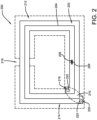
- the shape and size of the RFID tag 200 as shown in FIG. 2 is for illustrative purposes only and many other shapes and sizes of the RFID tag 200 are well within the scope of the present disclosure. Although dimensions of the RFID tag 200 (i.e., length, width, and height) are important design parameters for good performance, the RFID tag 200 may be any shape or size that ensures optimal performance during use.
- the RFID tag device 200 capable of withstanding a microwave oven comprises, in one embodiment, a planar structure of conductive antenna components 202 in a spiral type configuration, or any other suitable configuration as is known in the art.
- the present invention contemplates that the conductive antenna components 202 are metallic, but can be manufactured of any suitable material as is known in the art.
- the planar structure is shown as a rectangle, but can be any suitable shape as is known in the art, such as a circle, square, or triangle, etc.
- the planar structure with the spiral type configuration creates gaps 204 between the conductive antenna components 202.
- at least one gap 206 in the conductive antenna component 202 itself is where a RFID chip 208 is positioned, such that the RFID chip 208 is placed into a coil of the conductive antenna component 202.
- the center 218 of the microwave safe RFID tag device 200 and the outer edge 220 of the planar structure of conductive antenna components 202 may be bridged together with a conductive trace 222 creating an inductor (or bridge conductor) 210 across the microwave safe RFID tag device 200 and resonating at the wanted frequency.
- the microwave safe RFID tag device 200 comprises a second conductor 212 in the form of a split ring, or any other suitable shape as is known in the art. This second conductor (or ring conductor) 212 is separated from the bridge conductor (or coil conductor) 210 by a dielectric 214.
- This dielectric 214 is typically a plastic or an adhesive, or any other suitable dielectric material as is known in the art.
- the ring conductor 212 covers the majority of the conductive antenna components or coil 202 as shown in FIG. 2 , leaving a small gap 216 or open space that does not cover the coil 202.
- the shape and size of the split ring conductor 212 is designed as part of the overall microwave safe RFID tag device's 200 structure to provide a controlled interaction with the microwave field to minimize heating and prevent arcing.
- the design of the split ring conductor 212 varies, and any suitable shaped conductor as is known in the art can be used.
- common features of the split ring conductor 212 would be rounded corners, defined lengths of sides compared to a wavelength at the microwave frequency, and controlled gaps between ring elements, i.e., coils 202.
- the split ring conductor 212 capacitively couples to the coil 202 via the dielectric 214.
- the capacitance is ⁇ 106pF (picofarads).
- the equivalent coupling impedance to the coil 202 is 110 ohms, which will have minimal impact on the coil operation.
- the coupling impedance is ⁇ 0.61 ohms, effectively shorting the coil and ring. This prevents arcs between the coil elements and excessive currents flowing over the full length in the coil conductors 202.
- microwave safe RFID tag 200 can be read before or during the high-power microwave emission, i.e., 2.45 GHz.
- the ring conductor 212 is split (or gap) 216 to prevent it acting as a shorted turn, where it magnetically interacts with the coil antenna 202 as current will flow in it when it is placed in a magnetic field.
- the microwave current flows through the coil conductors 202 over a length defined by the gap 216 in the ring conductor 212 as on either side the coil conductors 202 are strongly coupled to the ring conductor 212.
- the size of the gap 216 is chosen such that any structure of the coil 202 in the gap 216 will not interact with the microwave field; for the purposes of this invention this should be less than one tenth of a wavelength at the microwave frequency, or approximately 12 mm.
- the RFID chip 208 of the microwave safe RFID tag 200 carries data related to the process the microwave oven is required to perform.
- data received from the RFID chip 208 may include, but is not limited to, a unique identifier for the RFID tag 200, product identification, product "use by” data, product “consume by” date, allergen information, cooking parameters for the food, instructions such as heat, stir, and dwell time after heating, etc.
- the RFID chip 208 could be used to prevent the microwave from operating to thaw, cook, heat or reheat the food without a manual override, thereby preventing the user from unknowingly consuming food that is no longer fit for consumption and preventing illness.
- This feature is particularly useful when, for example, the printed on information containing the product "use by” or “consume by” dates is no longer readable by the human eye, or gets separated from the food product.
- the needed authorization to override the RFID chip 208 could be different for different food products and/or for different users.
- the override needed for foods for infants, seafood, or foods with particular known allergens could be considered high risk and could require a specific password, rather than a simple yes/no or verbal confirmation.
- this particular product data can also be combined with data about the user, such as allergen information, to preventing cooking actions, sound an alarm, ask for verbal confirmation, etc.
- the RFID chip 208 can also be associated with a sensor that can detect whether the food product is thawed, chilled or frozen, and information or output from the sensor could, in turn, be used to modify the cooking parameters appropriately without further user interaction.
- the sensor output could be used to instruct the microwave oven to first thaw the food product at one microwave power setting, and then cook the food product at a different power setting.
- the sensor output may be used to instruct the microwave oven to bypass the thaw process and proceed straight to the cooking process, thereby saving both time and the energy necessary to operate the microwave oven during the thaw process.
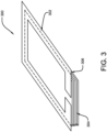
- the microwave safe RFID tag device 300 is shown with the shield conductor 302 in proximity to the HF RFID coil antenna (or coil conductor) 304. Further, the shield conductor 302 is separated from the coil conductor 304 via a dielectric (or substrate) 306, such as a plastic or adhesive, etc., or any other suitable material as is known in the art. Additionally, the microwave safe RFID tag device 300 can be made in a variety of ways. For example, the shield conductor 302 and the coil conductor 304 can be positioned on opposite surfaces of a substrate (or dielectric) 306 such as a PET substrate 306 wherein the coil conductor 304 is etched on one side of the PET substrate 306 and the shield conductor 302 is etched on the other.
- a substrate (or dielectric) 306 such as a PET substrate 306 wherein the coil conductor 304 is etched on one side of the PET substrate 306 and the shield conductor 302 is etched on the other.
- the shield conductor 302 and the coil conductor 304 can be positioned on opposite surfaces of a PET substrate 306 where the coil conductor 304 is laser cut on one side of the PET substrate 306 and the shield conductor 302 is laser cut on the other side of the PET substrate 306.
- the shield conductor 302 and the coil conductor 304 can be positioned on opposite surfaces of a PET substrate 306 where the coil conductor 304 is laser cut on one side of the PET substrate 306 and the shield conductor 302 is die cut on the other side of the PET substrate 306.
- the shield conductor 302 and the coil conductor 304 can be positioned on opposite surfaces of a PET substrate 306 where the coil conductor 304 is laser cut or etched on one surface of the PET substrate 306 and the shield conductor 302 is previously cut and applied with an adhesive to the other surface of the PET substrate 306.
- the shield conductor 302 and the coil conductor 304 can be on the same surface of a PET substrate 306 where the coil conductor 304 is laser cut or etched on one surface of the PET substrate 306 and the shield conductor 302 is previously cut and applied as an additive component with an adhesive to the same surface of the PET substrate 306.
- the shield conductor 302 and the coil conductor 304 can be either on the same or on opposite surfaces of the PET substrate 306 where the shield conductor 302 is applied as a printed structure, either on the back of the PET substrate 306 or on top of the coil conductor 304 with a suitable dielectric separator such as a varnish in between, or any other suitable dielectric material as is known in the art.
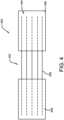
- FIG. 4 provides a view of the microwave safe RFID tag 400, specifically the area where the gap 402 in the split ring (or shield) conductor 404 is over the HF coil antenna conductor 406.
- the gap 402 discloses a large overlap area 408 on either side.
- the large overlap area 408 provides a low impedance coupling to the coil antenna conductor 406 on either side of the coil turns, as they are shorted together capacitively by the shield conductor 404.
- the shield conductor 404 acts as a single wide conductor capable of carrying the current across the gap 402. This prevents arcs between the coil elements (or turns) and excessive current flowing over the full length of the coil antenna conductor 406.
- the microwave current flows through the coil elements over a length defined by the gap 402, as on either side the coil antenna conductor 406 is strongly coupled to the split ring conductor 404.
- the size of the gap 402 is chosen such that any structure of the coil elements in the gap 402 will not interact with the microwave field, for example, the size of the gap 402 should be less than one tenth of a wavelength at the microwave frequency, or approximately 12 mm.
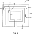
- FIG. 5 shows a further embodiment of the microwave safe RFID tag device 500 comprising a split ring (or shield) conductor 502 formed on one side of a substrate (or dielectric) 514, a coil antenna conductor 504 formed on an opposite side of the substrate 514, and a RFID chip 506.
- the split ring shield conductor 502 also acts as a HF bridge 516 between the center 508 and edge 510 of the coil antenna conductor 504 to make a continuous conductor to resonate with the RFID chip 506 at 13.56MHz.
- the bridging function is made by providing a low resistance (i.e., 10 ohm) path using crimped connections 512 between top and bottom conductors (i.e., shield conductor 502 and coil antenna conductor 504), or other connective means such as plated through holes, etc., or any other suitable connective means as is known in the art.
- crimped connections 512 between top and bottom conductors (i.e., shield conductor 502 and coil antenna conductor 504), or other connective means such as plated through holes, etc., or any other suitable connective means as is known in the art.
- the connection may be made by a suitable conductive adhesive as is known in the art.
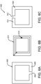
- FIGS. 6A-C show a further embodiment of the microwave safe RFID tag device 600 comprising two split ring shields (shield 1 602 and shield 2 604), a HF RFID coil antenna conductor (or HF RFID inlay) 610, and an RFID chip 616.
- the microwave safe RFID tag device 600 comprises a first split ring (or shield) conductor (shield 1) 602 with a gap 606 formed on the bottom edge 608 of the shield 1 conductor 602 and wherein the shield 1 conductor 602 is positioned on one side of the coil antenna conductor 610.
- the microwave safe RFID tag device 600 also comprises a second split ring (or shield) conductor (shield 2) 604 with a gap 612 formed on the top edge 614 of the shield 2 conductor 604 and wherein the shield 2 conductor 604 is positioned on the opposite side of the coil antenna conductor 610.
- shield 2 conductor 604 is positioned on the opposite side of the coil antenna conductor 610.
- the gaps 606 and 612 of the shield conductors (602 and 604) are positioned in different locations.
- both of the shield conductors (602 and 604) do not present a shorted turn to the coil antenna conductor 610, as the gaps (606 and 612) in shield 1 and shield 2 (602 and 604) are in different locations, no current flows in the coil antenna conductor 610 at either point as they bridge each other at 2.45GHz. Accordingly, the microwave safe RFID tag device 600 with two shield conductors (602 and 604) minimizes current flow in the coil antenna conductor 610.
- FIG. 7 shows a further embodiment for a microwave safe RFID tag device 700 comprising a split ring (or shield) conductor 702 formed on one side of a substrate (or dielectric) 704, a coil antenna conductor 706 formed on an opposite side of the substrate 704, and a RFID chip 718.
- the coil antenna conductor 706 also acts as a HF bridge 708 between the center 710 and edge 712 of the coil antenna conductor 706 to make a continuous conductor to resonate with the RFID chip 706 at 13.56MHz.
- the bridging function is made by providing a low resistance (i.e., 10 ohm) path using crimped connections 714 or other connective means such as plated through holes, etc., or any other suitable connective means as is known in the art.
- the coil antenna conductor 706 comprises small gaps 716, in the region of 10 ⁇ m to 100 ⁇ m or any other suitable size as is known in the art.
- the small gaps 716 are used to isolate the turns of the coil of the coil antenna conductor 706.
- the coupling capacitance between coil turns is a low impedance at 2.45 GHz, making the coil of the coil antenna conductor 706 look like a solid ring at 2.45 GHz with no gaps to prevent arcing.
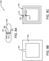
- FIGS. 8A-C discloses an embodiment of the microwave safe RFID tag device 800 comprising a RFID chip 806 connected to a strap 808, wherein the RFID chip 806 and strap 808 are positioned on a coil antenna conductor 820, and a split ring (or shield) conductor 802 is formed on top of the RFID chip 806 and strap 808.
- the RFID chip 806 is connected to two lines 810 and two pads 812 designed to connect (or bridge) it to the center 814 and outside edge 816 of the coil antenna conductor 820, giving a resonant circuit.
- the bridging (or connection) function is made by using crimped connections 818 or other connective means such as plated through holes, etc., or any other suitable connective means as is known in the art to connect with the two lines 810 and two pads 812 of the RFID chip 806.
- the strap 808 incorporates a top shield metalization which creates a shielded strap 808.
- This shielded strap 808 acts as a continuous conductor over the coil antenna conductor 820.
- the shield conductor 802 comprises a split ring (or gap) 804 as described above and is placed on top of the coil antenna conductor 820, with the gap 804 in the ring (or shield) conductor 802 shorted across at 2.45 GHz by the shielded strap 808 and capacitive coupling.
- this microwave safe RFID tag device 800 prevents any current from flowing in the coil antenna conductor 820 at the point where there is the gap 804 in the split ring shield conductor 802 to prevent arcing.
- RFID chip 806 data contained on RFID chip 806, such as "use by” or “consume by” data may be combined with other data, either from the manufacturer or relating to a particular user, to activate different cooking parameters, authorization levels necessary to override a cooking parameter, etc.
- Data relating to the user can include, but is not limited to, information regarding allergic reactions, time of day when cooking, age of the user, etc.
- This data along with the manufacturer data and/or product data, acts to control if a particular microwave operation (e.g., thawing, heating, reheating, cooking, etc.) is authorized and, in the event it is not directly authorized, it requires further action from the user.
- Said further action by a user can include entering a password, using a RFID card, using a near field communication (NFC) enabled phone, etc., or any other suitable action as is known in the art for taking action.
- NFC near field communication
- the process may begin with RFID tag 800 being read or interrogated and data concerning the RFID tagged product collected and analyzed.
- RFID tag 800 may be read or interrogated either inside or outside of the microwave cavity, depending on the particular RFID reader system being utilized. Based on said gathered data it can then be determined if the data read from RFID tag 800 shows that the tagged product is out of date (i.e., beyond its "best if used by" or “consume by” date). If the product is not out of date, then the microwave process can continue and the microwave oven control panel controls the appropriate microwave function (e.g., thawing, heating, reheating or cooking) on the RFID tagged product.
- the microwave oven control panel controls the appropriate microwave function (e.g., thawing, heating, reheating or cooking) on the RFID tagged product.
- the product is out of date then, it may be further determined if the product is a critical product. Whether a product is a "critical product” can be defined by any number of user specified parameters. For example, “critical products” could include baby products, products that tend to cause food poisoning if out of date, etc. If the product is not a critical product, then the microwave process could proceed directly to the desired microwave function (i.e., thawing, heating, reheating, cooking, etc.) and the microwave oven control panel controls the desired microwave function.
- the desired microwave function i.e., thawing, heating, reheating, cooking, etc.
- the microwave oven could proceed directly to the desired microwave function. This may occur with or without other parameters from the RFID tag, such as cooking instructions.
- a manual override or some form of verification may be required to continue. For example, if the product was to fall into a critical product category, for example shellfish or baby food, the microwave oven would require further authorization to override the lock out, such as a password. The same process could apply to products of food items containing allergens.
- any products presented to the microwave oven containing peanuts would require a high-level over-ride (e.g., a password) and possibly sound an alarm.
- a high-level over-ride e.g., a password
- Another aspect could relate to the age of the user. For example, a product that indicates that it becomes very hot during cooking, such as those containing high-levels of sugar syrup, would require an over-ride if children were present in the house to prevent the child from overheating the food product and suffering burning or scalding from the same.
- the process then proceeds directly to the desired microwave function (e.g., cooking, thawing, heating, reheating, etc.), and the microwave oven control panel controls the microwave process on the RFID tagged product.
- the desired microwave function e.g., cooking, thawing, heating, reheating, etc.
- the microwave oven control panel controls the microwave process on the RFID tagged product.
- differing levels of authorization could be established depending on the critical nature of the issue and/or the particular needs of the user.
- RFID tag 800 may further comprise some form of sensor.
- sensor can be a temperature sensor that can indicate if the RFID tagged product is thawed, chilled or frozen, or any other sensor as is known in the art, such as a moisture sensor, etc.
- the microwave oven can then select an appropriate cooking method (i.e., based on whether the food item is, for example, already thawed, chilled or frozen) as determined by the oven controller which then utilizes the data read from the RFID tagged product to select the appropriate microwave function to be performed.
- the output from the sensor could be used to instruct the microwave oven controller to first thaw the food product at one microwave power setting, and then cook the food product at a different power setting.
- the sensor output may be used to instruct the microwave oven controller to bypass the thaw process, and proceed straight to the cooking process, thereby saving both time and the energy necessary to operate the microwave oven during the thaw process, which is not necessary in this particular application.
- tag data obtained from RFID tag 800 may trigger a look up from an online web service or external database for the correct cooking parameter for that specific food item.
- the microwave oven controller may send user interface data to an online system/web service or external database to obtain additional information about the food item and how to prepare the same.
- the web service can provide additional information regarding the food item, such as tips on how to best cook the food item in the microwave, the appropriate power setting to use, or whether the food item is better cooked thawed, chilled or frozen, etc.
- the cooking parameters can then be combined with user preferences for some food items, for example, preferences such as the state of how the meat should be prepared, or the desired softness of vegetables, bread, etc.
- the oven controller may then utilize both the cooking parameters from the web service or other external database along with the user preferences to control the microwave cooking process of the food item.
- FIG. 9 illustrates another embodiment of the present invention.
- FIG. 9 illustrates an alternative form of shield to the split rings described previously; as illustrated, the alternative form is a startburst 905, a series of lines radiating from a central point inside the coil to the space outside the coil.
- the line widths are made so that they give adequate coupling, such as capacitive coupling, to the lines of the coil so that they are shorted at 2.45GHz, terminating the gaps in small arcs in the spaces between the gaps 901, but provide a relatively low coupling between the coils of the HF antenna to maintain performance, if the gaps are kept to a small proportion of a wavelength 907, for example lambda/20 or smaller, they interaction between the gaps and the 2.45GHz energy is minimized.
- the number of arms on the starburst can vary depending on the required level of termination of the gaps.
Landscapes
- Engineering & Computer Science (AREA)
- Physics & Mathematics (AREA)
- Computer Hardware Design (AREA)
- Microelectronics & Electronic Packaging (AREA)
- General Physics & Mathematics (AREA)
- Theoretical Computer Science (AREA)
- Electromagnetism (AREA)
- Computer Networks & Wireless Communication (AREA)
- Constitution Of High-Frequency Heating (AREA)
- Details Of Aerials (AREA)
- Electric Ovens (AREA)
- Support Of Aerials (AREA)
Claims (13)
- Étiquette d'identification par radiofréquence, RFID, tolérante aux émissions micro-ondes à 2,45 GHz (500) comprenant :une puce RFID (506) ;un conducteur d'antenne (504) ;un conducteur en anneau fendu (502) ; etun diélectrique (514) positionné entre le conducteur d'antenne et le conducteur en anneau fendu,dans lequel le conducteur d'antenne comprend un espace (204) et la puce RFID est positionnée dans l'espace, etcaractérisé en ce qu'un chemin relie le conducteur en anneau fendu formé sur un côté du diélectrique et le conducteur d'antenne formé sur un côté opposé du diélectrique, de sorte que le conducteur en anneau fendu agisse comme un pont HF (516) entre un centre (508) et un bord (510) du conducteur d'antenne.
- Étiquette RFID selon la revendication 1, dans laquelle le conducteur en anneau fendu (502) est couplé de manière capacitive au conducteur d'antenne (504).
- Étiquette RFID selon la revendication 1, dans laquelle le conducteur en anneau fendu (502) est formé sur un premier côté du diélectrique (514) et le conducteur d'antenne est formé sur un côté opposé du diélectrique.
- Étiquette RFID selon la revendication 1, dans laquelle un pont est formé entre un centre (508) et un bord extérieur (510) du conducteur d'antenne avec une trace conductrice (222) créant un inducteur (210).
- Étiquette RFID selon la revendication 1, dans laquelle le conducteur en anneau fendu (502) recouvre une partie substantielle du conducteur d'antenne (504).
- Étiquette RFID selon la revendication 5, dans laquelle le conducteur en anneau fendu (502) comprend un espace (216) où le conducteur en anneau fendu ne recouvre pas le conducteur d'antenne.
- Étiquette d'identification par radiofréquence, RFID, destinée à être utilisée dans un four à micro-ondes (600) tolérant les émissions micro-ondes à 2,45 GHz et comprenant :une puce RFID (616) ;un conducteur d'antenne à bobine (610) ;un premier conducteur en anneau fendu (602) ; etun second conducteur en anneau fendu (604),dans laquelle le conducteur d'antenne à bobine comprend un espace et la puce RFID est positionnée dans l'espace,caractérisée en ce que le premier conducteur en anneau fendu comprend un premier espace (606) et le second conducteur en anneau fendu comprend un second espace (612), et dans laquelle le second conducteur en anneau fendu est tourné à l'opposé du premier conducteur en anneau fendu de telle sorte que le premier espace ne s'aligne pas avec le second espace.
- Étiquette RFID selon la revendication 7, dans laquelle le conducteur d'antenne à bobine (610) est positionné entre les premier et second conducteurs en anneau fendu (602, 604).
- Étiquette RFID selon la revendication 7, dans laquelle le conducteur d'antenne à bobine (610) est couplé de manière capacitive aux premier et second conducteurs en anneau fendu (602, 604).
- Étiquette RFID selon la revendication 7, dans laquelle un pont est formé entre un centre (508) et un bord extérieur (510) du conducteur d'antenne à bobine (610) avec une trace conductrice (222) créant un inducteur (210).
- Étiquette d'identification par radiofréquence, RFID (800) destinée à être utilisée dans un champ micro-ondes tolérant les émissions micro-ondes à 2,45 GHz et comprenant :une puce RFID (806) fixée à une sangle (808), la sangle incorporant une métallisation de blindage supérieure pour créer une sangle blindée (808) ;un conducteur d'antenne à bobine (820) ; etun conducteur en anneau fendu (802) comprenant un espace (804) formé à l'intérieur, caractérisé en ce que la puce RFID (806) et la sangle blindée (802) sont positionnées sur le conducteur d'antenne à bobine (820) et dans lequel le conducteur en anneau fendu (802) est positionné au-dessus de la puce RFID (806) et de la sangle blindée (802), et dans laquelle la sangle blindée agit comme un conducteur continu sur le conducteur d'antenne à bobine, et dans laquelle le conducteur en anneau fendu (802) est placé au-dessus du conducteur d'antenne à bobine (820) avec l'espace (804) court-circuité par la sangle blindée (808) et le couplage capacitif.
- étiquette RFID selon la revendication 11 comprenant en outre un circuit résonant.
- Étiquette RFID selon la revendication 11, dans laquelle le conducteur en anneau fendu (802) est couplé de manière capacitive
au conducteur d'antenne à bobine (820).
Applications Claiming Priority (2)
| Application Number | Priority Date | Filing Date | Title |
|---|---|---|---|
| US201862690723P | 2018-06-27 | 2018-06-27 | |
| PCT/US2019/039485 WO2020006219A1 (fr) | 2018-06-27 | 2019-06-27 | Étiquettes rfid fonctionnant dans la bande haute fréquence résistante au four à micro-ondes |
Publications (2)
| Publication Number | Publication Date |
|---|---|
| EP3814995A1 EP3814995A1 (fr) | 2021-05-05 |
| EP3814995B1 true EP3814995B1 (fr) | 2025-01-08 |
Family
ID=67303523
Family Applications (1)
| Application Number | Title | Priority Date | Filing Date |
|---|---|---|---|
| EP19740458.5A Active EP3814995B1 (fr) | 2018-06-27 | 2019-06-27 | Étiquettes rfid fonctionnant dans la bande haute fréquence résistante au four à micro-ondes |
Country Status (5)
| Country | Link |
|---|---|
| US (1) | US11769938B2 (fr) |
| EP (1) | EP3814995B1 (fr) |
| JP (2) | JP7037520B2 (fr) |
| CN (1) | CN112639825B (fr) |
| WO (1) | WO2020006219A1 (fr) |
Families Citing this family (25)
| Publication number | Priority date | Publication date | Assignee | Title |
|---|---|---|---|---|
| WO2009143289A2 (fr) * | 2008-05-20 | 2009-11-26 | Deka Products Limited Partnership | Système rfid |
| WO2019224575A1 (fr) | 2018-05-22 | 2019-11-28 | Tyco Fire & Security Gmbh | Étiquette souple allongée |
| US12223814B2 (en) | 2019-09-16 | 2025-02-11 | Sensormatic Electronics, LLC | Security tag for textiles using conductive thread |
| US10970613B1 (en) | 2019-09-18 | 2021-04-06 | Sensormatic Electronics, LLC | Systems and methods for providing tags adapted to be incorporated with or in items |
| US11443160B2 (en) | 2019-09-18 | 2022-09-13 | Sensormatic Electronics, LLC | Systems and methods for laser tuning and attaching RFID tags to products |
| SE543687C2 (en) * | 2019-10-21 | 2021-06-08 | Stora Enso Oyj | Rfid tag with narrow gap for use in microwaveable food packages |
| US11055588B2 (en) | 2019-11-27 | 2021-07-06 | Sensormatic Electronics, LLC | Flexible water-resistant sensor tag |
| US12524640B2 (en) | 2019-11-27 | 2026-01-13 | Sensormatic Electronics, LLC | Flexible water-resistant sensor tag |
| BR112022014785A2 (pt) | 2020-01-27 | 2022-09-20 | Avery Dennison Retail Information Services Llc | Método para autenticar um item |
| CN111860014B (zh) * | 2020-07-10 | 2022-02-11 | 西南科技大学 | 一种无源rfid标签及识别金属深度裂纹的方法 |
| US12380291B2 (en) | 2020-10-23 | 2025-08-05 | Avery Dennison Retail Information Services Llc | Systems containing multiple read zones and methods of use thereof |
| US20230410041A1 (en) | 2020-10-23 | 2023-12-21 | Avery Dennison Retail Information Services Llc | Methods for detecting variable weight-price items in detector-based inventory management and/or shopping systems |
| CN116724312A (zh) | 2020-11-18 | 2023-09-08 | 艾利丹尼森零售信息服务有限公司 | 用于确定物品正在离开还是返回推销场所的方法和系统 |
| US11755874B2 (en) | 2021-03-03 | 2023-09-12 | Sensormatic Electronics, LLC | Methods and systems for heat applied sensor tag |
| JP7733752B2 (ja) * | 2021-06-24 | 2025-09-03 | エイヴェリー デニソン リテール インフォメーション サービシズ リミテッド ライアビリティ カンパニー | マイクロ波耐性rfidシステム及び構成要素 |
| DE102021118103B3 (de) | 2021-07-13 | 2022-10-27 | Etifix Gmbh | Mikrowellentaugliches smart label |
| PL4120133T3 (pl) | 2021-07-13 | 2024-08-05 | Etifix Gmbh | Układ, składający się z inteligentnej etykiety i elementu osłonowego oraz część zastawy stołowej, nadająca się do kuchenki mikrofalowej |
| GB2613548A (en) | 2021-12-03 | 2023-06-14 | Haydale Graphene Ind Plc | Rfid |
| US11869324B2 (en) | 2021-12-23 | 2024-01-09 | Sensormatic Electronics, LLC | Securing a security tag into an article |
| WO2023178287A1 (fr) | 2022-03-16 | 2023-09-21 | Avery Dennison Retail Information Services, Llc | Procédés d'identification d'un événement d'intérêt pour un article dans une chaîne d'approvisionnement |
| TW202350060A (zh) * | 2022-05-31 | 2023-12-16 | 瑞昱半導體股份有限公司 | 屏蔽電路與半導體裝置 |
| CN115409145A (zh) * | 2022-09-28 | 2022-11-29 | 上海芯符智能科技有限公司 | 一种rfid标签和具有rfid标签的包装 |
| CN116979251A (zh) * | 2023-08-30 | 2023-10-31 | 南京信息职业技术学院 | 一种准背腔式的小型抗金属超高频标签天线 |
| US12223379B1 (en) * | 2023-12-29 | 2025-02-11 | Logistics and Supply Chain MultiTech R&D Centre Limited | Microwave-tolerant RFID tag |
| US20260015148A1 (en) * | 2024-07-10 | 2026-01-15 | Mold-Rite Plastics, LLC | Rfid inlay assembly and closure containing same |
Citations (1)
| Publication number | Priority date | Publication date | Assignee | Title |
|---|---|---|---|---|
| US20180143480A1 (en) * | 2015-07-23 | 2018-05-24 | Fujifilm Corporation | Liquid crystal cell, three-dimensional structural liquid crystal cell precursor, and method of manufacturing three-dimensional structural liquid crystal cell |
Family Cites Families (115)
| Publication number | Priority date | Publication date | Assignee | Title |
|---|---|---|---|---|
| USD383465S (en) | 1995-11-30 | 1997-09-09 | Hideki Okuchi | Auxiliary antenna for cellular phone |
| DE19654902C2 (de) | 1996-03-15 | 2000-02-03 | David Finn | Chipkarte |
| JP2000090637A (ja) * | 1998-09-09 | 2000-03-31 | Sony Corp | カセットラベル、ビデオテープカセット及びicカード |
| JP2000163543A (ja) * | 1998-11-27 | 2000-06-16 | Hitachi Ltd | 無線icカードおよびその製造方法 |
| US8052061B2 (en) | 2002-08-07 | 2011-11-08 | Vanguard Identification Systems, Inc. | Permanent RFID luggage tag with security features |
| DE19951561A1 (de) * | 1999-10-27 | 2001-05-03 | Meto International Gmbh | Sicherungselement für die elektronischen Artikelsicherung |
| JP2001143043A (ja) * | 1999-11-15 | 2001-05-25 | Sekisui Chem Co Ltd | 非接触式icカード及び非接触式icカードの継線方法 |
| WO2001063189A1 (fr) | 2000-02-28 | 2001-08-30 | Dai Nippon Printing Co., Ltd. | Systeme de refrigeration automatique, refrigerateur, systeme de cuisson automatique et four a micro-ondes |
| JP2001317741A (ja) | 2000-02-28 | 2001-11-16 | Dainippon Printing Co Ltd | 食品の自動調理システムと電子レンジ |
| JP2001326526A (ja) * | 2000-05-16 | 2001-11-22 | Mitsubishi Electric Corp | シールドアンテナコイル |
| JP2002049905A (ja) * | 2000-08-03 | 2002-02-15 | Dainippon Printing Co Ltd | 非接触データキャリア付きパッケージと製品情報管理方法 |
| JP2002150248A (ja) * | 2000-11-14 | 2002-05-24 | Dainippon Printing Co Ltd | 衝撃感知センサ付きデータキャリア装置 |
| US6924688B1 (en) | 2000-11-28 | 2005-08-02 | Precision Dynamics Corporation | Rectifying charge storage device with antenna |
| WO2002099764A1 (fr) | 2001-06-05 | 2002-12-12 | Motorola, Inc. | Systeme de communication de donnees a alimentation capacitive comprenant un dispositif d'etiquette et de support de circuit |
| JP2003030612A (ja) | 2001-07-19 | 2003-01-31 | Oji Paper Co Ltd | Icチップ実装体 |
| JP2003087044A (ja) | 2001-09-12 | 2003-03-20 | Mitsubishi Materials Corp | Rfid用アンテナ及び該アンテナを備えたrfidシステム |
| US7214569B2 (en) | 2002-01-23 | 2007-05-08 | Alien Technology Corporation | Apparatus incorporating small-feature-size and large-feature-size components and method for making same |
| MXPA05001550A (es) | 2002-08-08 | 2005-10-05 | Neology Inc | Dispositivo de identificacion de frecuencias multiples. |
| US7224280B2 (en) | 2002-12-31 | 2007-05-29 | Avery Dennison Corporation | RFID device and method of forming |
| US11334728B2 (en) | 2003-03-03 | 2022-05-17 | Lone Star Scm Systems, Lp | Interrogator and interrogation system employing the same |
| US7652636B2 (en) | 2003-04-10 | 2010-01-26 | Avery Dennison Corporation | RFID devices having self-compensating antennas and conductive shields |
| US20040234653A1 (en) | 2003-05-22 | 2004-11-25 | Cogley Paul A. | Susceptor tray and mirowavable dough products |
| US20040238534A1 (en) | 2003-05-29 | 2004-12-02 | Mast Roy Lee | Package for microwave cooking |
| JP4452583B2 (ja) * | 2003-08-29 | 2010-04-21 | セイコーエプソン株式会社 | ループアンテナ装置 |
| JP2005101987A (ja) | 2003-09-25 | 2005-04-14 | Matsushita Electric Works Ltd | 集積無線idタグ |
| US7471173B2 (en) | 2003-11-06 | 2008-12-30 | Murata Manufacturing Co., Ltd | Resonator, filter, nonreciprocal circuit device, and communication apparatus |
| US6999028B2 (en) | 2003-12-23 | 2006-02-14 | 3M Innovative Properties Company | Ultra high frequency radio frequency identification tag |
| JP2005216044A (ja) | 2004-01-30 | 2005-08-11 | Seiko Precision Inc | 非接触icカード及び非接触icカード用ホルダ |
| US7421245B2 (en) * | 2004-02-20 | 2008-09-02 | 3M Innovative Properties Company | Field-shaping shielding for radio frequency identification (RFID) system |
| JP2005252853A (ja) | 2004-03-05 | 2005-09-15 | Fec Inc | Rf−id用アンテナ |
| US20120062367A1 (en) | 2004-04-06 | 2012-03-15 | Vanguard Identification Systems, Inc. | Near field communication enabled permanent rfid luggage tag |
| JP2005323019A (ja) | 2004-05-07 | 2005-11-17 | Pegasus Net Kk | Rfidタグ用ブースターアンテナ |
| US7158033B2 (en) | 2004-09-01 | 2007-01-02 | Avery Dennison Corporation | RFID device with combined reactive coupler |
| JP3960329B2 (ja) | 2004-11-02 | 2007-08-15 | 松下電器産業株式会社 | 加熱調理器およびそのプログラム |
| WO2006048964A1 (fr) | 2004-11-02 | 2006-05-11 | Matsushita Electric Industrial Co., Ltd. | Dispositif de chauffage |
| US7452748B1 (en) * | 2004-11-08 | 2008-11-18 | Alien Technology Corporation | Strap assembly comprising functional block deposited therein and method of making same |
| JP4281683B2 (ja) | 2004-12-16 | 2009-06-17 | 株式会社デンソー | Icタグの取付構造 |
| US7355516B2 (en) * | 2004-12-23 | 2008-04-08 | Checkpoint Systems, Inc. | Method and apparatus for protecting culinary products |
| CN100587745C (zh) * | 2004-12-23 | 2010-02-03 | 关卡系统股份有限公司 | 保护烹饪产品的方法与仪器 |
| GB2423366B (en) | 2005-02-16 | 2010-02-24 | Cintex Ltd | Metal detector |
| JP2007086863A (ja) | 2005-09-20 | 2007-04-05 | Fuji Xerox Co Ltd | 非接触icタグ、非接触icタグを備えた部材のパッケージ及び非接触icタグを備えた部材を用いる装置 |
| KR100717881B1 (ko) | 2005-09-23 | 2007-05-14 | 한국전자통신연구원 | 모바일 rfⅰd 리더 및 그 제어 방법 |
| JP2007089054A (ja) | 2005-09-26 | 2007-04-05 | Nippon Telegr & Teleph Corp <Ntt> | Rfidタグのアンテナ |
| JP4761952B2 (ja) | 2005-12-14 | 2011-08-31 | 富士通株式会社 | Rfidタグ |
| USD553124S1 (en) | 2006-01-05 | 2007-10-16 | Novariant Inc. | Roof module |
| US7391325B2 (en) | 2006-01-13 | 2008-06-24 | Honeywell International Inc. | Multifunctional multichip system for wireless sensing |
| US8786510B2 (en) | 2006-01-24 | 2014-07-22 | Avery Dennison Corporation | Radio frequency (RF) antenna containing element and methods of making the same |
| EP1821241A3 (fr) | 2006-02-15 | 2008-07-23 | Assa Abloy AB | Unité de transpondeur sans contact à fréquence hybride, module pour celle-ci et procédé de fabrication de celle-ci |
| USD546819S1 (en) | 2006-02-17 | 2007-07-17 | Impinj, Inc. | Radio frequency identification tag antenna assembly |
| US7646304B2 (en) | 2006-04-10 | 2010-01-12 | Checkpoint Systems, Inc. | Transfer tape strap process |
| ES2444222T3 (es) | 2006-07-10 | 2014-02-24 | Goji Limited | Preparación de alimentos |
| KR101478810B1 (ko) | 2006-07-28 | 2015-01-02 | 가부시키가이샤 한도오따이 에네루기 켄큐쇼 | 축전 장치 |
| US9607188B2 (en) | 2014-09-29 | 2017-03-28 | Rfmicron, Inc. | Radio frequency identification (RFID) tag(s) and sensor(s) |
| US20080122631A1 (en) | 2006-11-29 | 2008-05-29 | Intermec Ip Corp. | Multiple band / wide band radio frequency identification (rfid) tag, such as for use as a metal mount tag |
| US7535366B2 (en) * | 2006-12-13 | 2009-05-19 | 3M Innovative Properties Company | Microwaveable radio frequency identification tags |
| MX2009007509A (es) | 2007-01-11 | 2009-07-21 | Lg Electronics Inc | Electrodomestico para cocinar, sistema de control para el dispositivo para cocinar y metodo para controlar el dispositivo para cocinar. |
| US7965186B2 (en) | 2007-03-09 | 2011-06-21 | Corning Cable Systems, Llc | Passive RFID elements having visual indicators |
| GB2455779A (en) | 2007-12-21 | 2009-06-24 | Novalia Ltd | Reader and electronic tag with conductive tracks having narrow and wide sections |
| EP2722796B1 (fr) | 2007-12-22 | 2016-05-11 | Baumer hhs GmbH | Procédé de production d'un produit imprimé comprenant un transpondeur RFID |
| US7744005B2 (en) * | 2008-01-16 | 2010-06-29 | Taiwan Name Plate Co., Ltd. | Induction card with a printed antenna |
| USD634738S1 (en) | 2008-01-30 | 2011-03-22 | Yfy Rfid Technologies Company Limited | RFID antenna |
| US8056814B2 (en) * | 2008-02-27 | 2011-11-15 | Tagsys Sas | Combined EAS/RFID tag |
| EP2251934B1 (fr) | 2008-03-03 | 2018-05-02 | Murata Manufacturing Co. Ltd. | Dispositif à ci sans fil et système de communication sans fil |
| JP4518211B2 (ja) | 2008-03-03 | 2010-08-04 | 株式会社村田製作所 | 複合アンテナ |
| US8289165B2 (en) | 2008-06-11 | 2012-10-16 | Avery Dennison Corporation | RFID device with conductive loop shield |
| JPWO2009157081A1 (ja) | 2008-06-26 | 2011-12-01 | 富士通株式会社 | Rfidタグ |
| US20100000980A1 (en) | 2008-07-02 | 2010-01-07 | Bogdan Popescu | Induction Heating System with Versatile Inductive Cartridge |
| JP5094630B2 (ja) | 2008-08-11 | 2012-12-12 | 株式会社日立製作所 | Icタグ |
| US8228197B2 (en) | 2008-11-10 | 2012-07-24 | Pouch Pac Innovations, Llc | Flexible pouch with smart tags |
| US8174388B2 (en) | 2008-12-10 | 2012-05-08 | Sensormatic Electronics, LLC | Method and system for deactivation of combination EAS/RFID tags |
| CN102273012B (zh) | 2009-01-09 | 2013-11-20 | 株式会社村田制作所 | 无线ic器件及无线ic模块 |
| US9277601B2 (en) | 2009-02-26 | 2016-03-01 | International Business Machines Corporation | Operating an appliance based on cooking instructions embedded in an RFID product tag |
| JP5173896B2 (ja) | 2009-03-09 | 2013-04-03 | レンゴー株式会社 | Rfidタグ用ブースタアンテナ |
| US8286887B2 (en) | 2009-03-10 | 2012-10-16 | Wal-Mart Stores, Inc. | RFID tag sensors and methods |
| JP5204032B2 (ja) | 2009-05-07 | 2013-06-05 | レンゴー株式会社 | Rfidタグ用ブースタアンテナ |
| JP2011100181A (ja) | 2009-11-04 | 2011-05-19 | Toppan Printing Co Ltd | 非接触icラベルとアンテナ内蔵被接着体 |
| US9368580B2 (en) | 2009-12-04 | 2016-06-14 | Sensor Electronic Technology, Inc. | Semiconductor material doping |
| US8833664B2 (en) | 2009-12-18 | 2014-09-16 | Yu Yung Choi | Enhanced performance and security RFID device |
| JP5464028B2 (ja) | 2010-04-19 | 2014-04-09 | 凸版印刷株式会社 | 偽変造防止用icラベル |
| JP2010231797A (ja) | 2010-05-13 | 2010-10-14 | Dainippon Printing Co Ltd | 非接触データキャリアを付したパッケージ |
| US8511569B1 (en) | 2010-11-02 | 2013-08-20 | Impinj, Inc. | RFID integrated circuit to strap mounting system |
| EP2580715B1 (fr) | 2010-06-14 | 2019-05-22 | Avery Dennison Corporation | Procede, systeme et appareil pour preparation des etiquettes rfid en petite serie |
| WO2012020748A1 (fr) | 2010-08-10 | 2012-02-16 | 株式会社村田製作所 | Carte de circuit imprimé et système de communication sans fil |
| US8646695B2 (en) | 2010-10-01 | 2014-02-11 | Disney Enterprises, Inc. | Combined HF and UHF RFID device |
| WO2012073113A2 (fr) | 2010-11-29 | 2012-06-07 | Goji Ltd. | Système, appareil, et procédé pour cuisson à l'aide d'un four rf |
| WO2013156389A1 (fr) * | 2012-04-19 | 2013-10-24 | Smartrac Ip B.V. | Structure de boucle intégrée pour identification par radiofréquence |
| US20130313328A1 (en) | 2012-05-25 | 2013-11-28 | Omni-Id Cayman Limited | Shielded Cavity Backed Slot Decoupled RFID TAGS |
| JP6050961B2 (ja) | 2012-06-18 | 2016-12-21 | トッパン・フォームズ株式会社 | 非接触型データ受送信体 |
| USD697900S1 (en) | 2012-07-18 | 2014-01-21 | Kmw Inc. | Antenna radome |
| MX342900B (es) | 2012-07-19 | 2016-10-18 | 3M Innovative Properties Co | Etiqueta de blindaje electromagnetico. |
| BR112015032345B8 (pt) | 2013-06-24 | 2022-08-30 | Avery Dennison Corp | Etiquetas de mercadoria usando um condutor de antena |
| US9378451B2 (en) | 2013-08-14 | 2016-06-28 | Avery Dennison Corporation | RFID labels with digitally printed indicia for matching merchandise appearance characteristics |
| US9275322B2 (en) | 2013-11-25 | 2016-03-01 | VivaLnk Limited (Cayman Islands) | Stretchable multi-layer wearable tag capable of wireless communications |
| USD716774S1 (en) | 2014-04-04 | 2014-11-04 | Avery Dennison Corporation | RFID inlay |
| US9874603B2 (en) | 2014-07-07 | 2018-01-23 | Avery Dennison Retail Information Services, Llc | System and method for capacitive coupling testing |
| USD763833S1 (en) | 2014-10-01 | 2016-08-16 | Ohio State Innovation Foundation | RFID tag |
| WO2016060938A2 (fr) | 2014-10-08 | 2016-04-21 | RF Micron, Inc. | Étiquette(s) et capteurs d'humidité d'identification par radiofréquence (rfid) présentant une détection étendue par l'intermédiaire de capillaires |
| USD880460S1 (en) | 2015-06-12 | 2020-04-07 | Avery Dennison Retail Information Services, Llc | Antenna |
| US10268945B1 (en) | 2015-06-30 | 2019-04-23 | Amazon Technologies, Inc. | RFID tags |
| US9418262B1 (en) | 2015-07-22 | 2016-08-16 | Vectare, Inc. | Method to differentiate radio frequency identification tags from other metal objects |
| WO2017094794A1 (fr) | 2015-12-02 | 2017-06-08 | 株式会社村田製作所 | Article hygiénique muni d'une étiquette rfid de détection d'humidité |
| JP6350766B2 (ja) | 2016-01-18 | 2018-07-04 | 株式会社村田製作所 | アンテナ装置および電子機器 |
| USD795228S1 (en) | 2016-03-04 | 2017-08-22 | Airgain Incorporated | Antenna |
| US10311355B1 (en) | 2016-03-31 | 2019-06-04 | Amazon Technologies, Inc. | RFID tags |
| KR102556536B1 (ko) | 2016-09-30 | 2023-07-17 | 삼성전자주식회사 | 조리 기기 및 조리 기기의 제어 방법 |
| USD812045S1 (en) | 2016-10-06 | 2018-03-06 | Avery Dennison Retail Information Services, Llc | Antenna |
| GB2554952A (en) | 2016-10-17 | 2018-04-18 | Parkside Flexibles Europe Ltd | Electronic identifier for packaging |
| CN114781571B (zh) | 2016-12-29 | 2025-11-21 | 艾利丹尼森零售信息服务公司 | 用于结合至可微波食品包装中的具有屏蔽结构的rfid标签 |
| USD837769S1 (en) | 2017-05-22 | 2019-01-08 | Shenzhen Antop Technology Limited | Antenna |
| US10733495B2 (en) | 2017-08-30 | 2020-08-04 | Precision Dynamics Corporation | Wearable RFID device |
| CN207424902U (zh) * | 2017-11-17 | 2018-05-29 | 厦门信达物联科技有限公司 | 一种应用于无人超市的电子标签 |
| JP2021522573A (ja) | 2018-04-20 | 2021-08-30 | アベリー・デニソン・リテイル・インフォメーション・サービシズ・リミテッド・ライアビリティ・カンパニーAvery Dennison Retail Information Services, Llc | 電子レンジ対応の食品包装に組み込むための遮蔽型rfidタグ |
| EP3814994A1 (fr) | 2018-06-27 | 2021-05-05 | Avery Dennison Retail Information Services, LLC | Étiquettes rfid tolérantes aux émissions à effet de champ fixées à des produits pour commander un processus de cuisson |
| CN109389203A (zh) | 2018-10-11 | 2019-02-26 | 江苏金羿先磁新材料科技有限公司 | 一种抗金属rfid标签频点偏移调整方法 |
| USD855039S1 (en) | 2018-10-26 | 2019-07-30 | Pvc Antenna Inc. | Antenna |
-
2019
- 2019-06-27 EP EP19740458.5A patent/EP3814995B1/fr active Active
- 2019-06-27 CN CN201980056375.0A patent/CN112639825B/zh active Active
- 2019-06-27 JP JP2019119382A patent/JP7037520B2/ja active Active
- 2019-06-27 US US16/454,939 patent/US11769938B2/en active Active
- 2019-06-27 WO PCT/US2019/039485 patent/WO2020006219A1/fr not_active Ceased
-
2022
- 2022-01-04 JP JP2022000135A patent/JP7457736B2/ja active Active
Patent Citations (1)
| Publication number | Priority date | Publication date | Assignee | Title |
|---|---|---|---|---|
| US20180143480A1 (en) * | 2015-07-23 | 2018-05-24 | Fujifilm Corporation | Liquid crystal cell, three-dimensional structural liquid crystal cell precursor, and method of manufacturing three-dimensional structural liquid crystal cell |
Also Published As
| Publication number | Publication date |
|---|---|
| WO2020006219A1 (fr) | 2020-01-02 |
| CN112639825B (zh) | 2024-03-19 |
| US11769938B2 (en) | 2023-09-26 |
| JP2020010330A (ja) | 2020-01-16 |
| CN112639825A (zh) | 2021-04-09 |
| US20200006840A1 (en) | 2020-01-02 |
| JP2022050515A (ja) | 2022-03-30 |
| EP3814995A1 (fr) | 2021-05-05 |
| JP7037520B2 (ja) | 2022-03-16 |
| JP7457736B2 (ja) | 2024-03-28 |
Similar Documents
| Publication | Publication Date | Title |
|---|---|---|
| EP3814995B1 (fr) | Étiquettes rfid fonctionnant dans la bande haute fréquence résistante au four à micro-ondes | |
| CN112655002A (zh) | 附接到产品以控制烹饪过程的耐受高场发射的rfid标签 | |
| US11929544B2 (en) | Wireless communication device using a radio frequency identification (RFID) technology for data communication in a non-contact manner by an induction electromagnetic field or a radio wave | |
| US7154449B2 (en) | Antenna | |
| AU2022297735B2 (en) | Microwave tolerant rfid system and components | |
| EP3563297B1 (fr) | Sangle à double fonction pour éléments résonants et antennes à ultra haute fréquence | |
| EP3782077B1 (fr) | Procédé d'utilisation de straps rfid blindés avec des modèles d'étiquettes rfid | |
| US20080048863A1 (en) | Combination Eas And Rfid Label Or Tag With Controllable Read Range | |
| KR101874323B1 (ko) | 니어 필드 애플리케이션들을 위한 소형 광대역 루프 안테나 | |
| US11916316B2 (en) | Wireless communication device | |
| CN114930343A (zh) | 用于可微波食品包装的具有窄间隙的rfid标签 | |
| CN215732213U (zh) | 无线通信设备 | |
| EP3555813A1 (fr) | Étiquette rfid passive insensible à la surface à longue portée | |
| Wickramasinghe et al. | A Miniaturized Printed Dipole with Non-Uniform Meander Lines for Ultra High Frequency–Radio Frequency Identification Passive Tags | |
| CN213878432U (zh) | 无线通信设备 | |
| CN215732214U (zh) | 无线通信设备 | |
| EP4643269A1 (fr) | Incrustations d'identification par radiofréquence destinées à être utilisées avec des emballages alimentaires micro-ondables ou à incorporées dans lesdits emballages alimentaires micro-ondables | |
| WO2025108542A1 (fr) | Étiquette rfid | |
| WO2025221742A1 (fr) | Antenne rfid pour rejeter des signaux rf indésirables | |
| KR20090105053A (ko) | 등방성 방사특성을 가진 극초단파대역 rfid 태그안테나 |
Legal Events
| Date | Code | Title | Description |
|---|---|---|---|
| STAA | Information on the status of an ep patent application or granted ep patent |
Free format text: STATUS: UNKNOWN |
|
| STAA | Information on the status of an ep patent application or granted ep patent |
Free format text: STATUS: THE INTERNATIONAL PUBLICATION HAS BEEN MADE |
|
| PUAI | Public reference made under article 153(3) epc to a published international application that has entered the european phase |
Free format text: ORIGINAL CODE: 0009012 |
|
| STAA | Information on the status of an ep patent application or granted ep patent |
Free format text: STATUS: REQUEST FOR EXAMINATION WAS MADE |
|
| 17P | Request for examination filed |
Effective date: 20210113 |
|
| AK | Designated contracting states |
Kind code of ref document: A1 Designated state(s): AL AT BE BG CH CY CZ DE DK EE ES FI FR GB GR HR HU IE IS IT LI LT LU LV MC MK MT NL NO PL PT RO RS SE SI SK SM TR |
|
| STAA | Information on the status of an ep patent application or granted ep patent |
Free format text: STATUS: EXAMINATION IS IN PROGRESS |
|
| DAV | Request for validation of the european patent (deleted) | ||
| DAX | Request for extension of the european patent (deleted) | ||
| 17Q | First examination report despatched |
Effective date: 20210928 |
|
| RAP3 | Party data changed (applicant data changed or rights of an application transferred) |
Owner name: AVERY DENNISON RETAIL INFORMATION SERVICES LLC |
|
| GRAP | Despatch of communication of intention to grant a patent |
Free format text: ORIGINAL CODE: EPIDOSNIGR1 |
|
| STAA | Information on the status of an ep patent application or granted ep patent |
Free format text: STATUS: GRANT OF PATENT IS INTENDED |
|
| INTG | Intention to grant announced |
Effective date: 20240315 |
|
| GRAJ | Information related to disapproval of communication of intention to grant by the applicant or resumption of examination proceedings by the epo deleted |
Free format text: ORIGINAL CODE: EPIDOSDIGR1 |
|
| STAA | Information on the status of an ep patent application or granted ep patent |
Free format text: STATUS: EXAMINATION IS IN PROGRESS |
|
| GRAP | Despatch of communication of intention to grant a patent |
Free format text: ORIGINAL CODE: EPIDOSNIGR1 |
|
| STAA | Information on the status of an ep patent application or granted ep patent |
Free format text: STATUS: GRANT OF PATENT IS INTENDED |
|
| INTC | Intention to grant announced (deleted) | ||
| INTG | Intention to grant announced |
Effective date: 20240717 |
|
| GRAJ | Information related to disapproval of communication of intention to grant by the applicant or resumption of examination proceedings by the epo deleted |
Free format text: ORIGINAL CODE: EPIDOSDIGR1 |
|
| STAA | Information on the status of an ep patent application or granted ep patent |
Free format text: STATUS: EXAMINATION IS IN PROGRESS |
|
| GRAP | Despatch of communication of intention to grant a patent |
Free format text: ORIGINAL CODE: EPIDOSNIGR1 |
|
| STAA | Information on the status of an ep patent application or granted ep patent |
Free format text: STATUS: GRANT OF PATENT IS INTENDED |
|
| INTC | Intention to grant announced (deleted) | ||
| INTG | Intention to grant announced |
Effective date: 20241001 |
|
| GRAS | Grant fee paid |
Free format text: ORIGINAL CODE: EPIDOSNIGR3 |
|
| GRAA | (expected) grant |
Free format text: ORIGINAL CODE: 0009210 |
|
| STAA | Information on the status of an ep patent application or granted ep patent |
Free format text: STATUS: THE PATENT HAS BEEN GRANTED |
|
| P01 | Opt-out of the competence of the unified patent court (upc) registered |
Free format text: CASE NUMBER: APP_62439/2024 Effective date: 20241122 |
|
| AK | Designated contracting states |
Kind code of ref document: B1 Designated state(s): AL AT BE BG CH CY CZ DE DK EE ES FI FR GB GR HR HU IE IS IT LI LT LU LV MC MK MT NL NO PL PT RO RS SE SI SK SM TR |
|
| REG | Reference to a national code |
Ref country code: GB Ref legal event code: FG4D |
|
| REG | Reference to a national code |
Ref country code: CH Ref legal event code: EP |
|
| REG | Reference to a national code |
Ref country code: DE Ref legal event code: R096 Ref document number: 602019064608 Country of ref document: DE |
|
| REG | Reference to a national code |
Ref country code: IE Ref legal event code: FG4D |
|
| REG | Reference to a national code |
Ref country code: LT Ref legal event code: MG9D |
|
| REG | Reference to a national code |
Ref country code: NL Ref legal event code: MP Effective date: 20250108 |
|
| REG | Reference to a national code |
Ref country code: AT Ref legal event code: MK05 Ref document number: 1758819 Country of ref document: AT Kind code of ref document: T Effective date: 20250108 |
|
| PG25 | Lapsed in a contracting state [announced via postgrant information from national office to epo] |
Ref country code: NL Free format text: LAPSE BECAUSE OF FAILURE TO SUBMIT A TRANSLATION OF THE DESCRIPTION OR TO PAY THE FEE WITHIN THE PRESCRIBED TIME-LIMIT Effective date: 20250108 |
|
| PG25 | Lapsed in a contracting state [announced via postgrant information from national office to epo] |
Ref country code: RS Free format text: LAPSE BECAUSE OF FAILURE TO SUBMIT A TRANSLATION OF THE DESCRIPTION OR TO PAY THE FEE WITHIN THE PRESCRIBED TIME-LIMIT Effective date: 20250408 |
|
| PG25 | Lapsed in a contracting state [announced via postgrant information from national office to epo] |
Ref country code: FI Free format text: LAPSE BECAUSE OF FAILURE TO SUBMIT A TRANSLATION OF THE DESCRIPTION OR TO PAY THE FEE WITHIN THE PRESCRIBED TIME-LIMIT Effective date: 20250108 |
|
| PG25 | Lapsed in a contracting state [announced via postgrant information from national office to epo] |
Ref country code: PL Free format text: LAPSE BECAUSE OF FAILURE TO SUBMIT A TRANSLATION OF THE DESCRIPTION OR TO PAY THE FEE WITHIN THE PRESCRIBED TIME-LIMIT Effective date: 20250108 |
|
| PGFP | Annual fee paid to national office [announced via postgrant information from national office to epo] |
Ref country code: DE Payment date: 20250509 Year of fee payment: 7 |
|
| PG25 | Lapsed in a contracting state [announced via postgrant information from national office to epo] |
Ref country code: ES Free format text: LAPSE BECAUSE OF FAILURE TO SUBMIT A TRANSLATION OF THE DESCRIPTION OR TO PAY THE FEE WITHIN THE PRESCRIBED TIME-LIMIT Effective date: 20250108 |
|
| PGFP | Annual fee paid to national office [announced via postgrant information from national office to epo] |
Ref country code: GB Payment date: 20250508 Year of fee payment: 7 |
|
| PG25 | Lapsed in a contracting state [announced via postgrant information from national office to epo] |
Ref country code: IS Free format text: LAPSE BECAUSE OF FAILURE TO SUBMIT A TRANSLATION OF THE DESCRIPTION OR TO PAY THE FEE WITHIN THE PRESCRIBED TIME-LIMIT Effective date: 20250508 Ref country code: NO Free format text: LAPSE BECAUSE OF FAILURE TO SUBMIT A TRANSLATION OF THE DESCRIPTION OR TO PAY THE FEE WITHIN THE PRESCRIBED TIME-LIMIT Effective date: 20250408 |
|
| PG25 | Lapsed in a contracting state [announced via postgrant information from national office to epo] |
Ref country code: HR Free format text: LAPSE BECAUSE OF FAILURE TO SUBMIT A TRANSLATION OF THE DESCRIPTION OR TO PAY THE FEE WITHIN THE PRESCRIBED TIME-LIMIT Effective date: 20250108 |
|
| PG25 | Lapsed in a contracting state [announced via postgrant information from national office to epo] |
Ref country code: LV Free format text: LAPSE BECAUSE OF FAILURE TO SUBMIT A TRANSLATION OF THE DESCRIPTION OR TO PAY THE FEE WITHIN THE PRESCRIBED TIME-LIMIT Effective date: 20250108 Ref country code: PT Free format text: LAPSE BECAUSE OF FAILURE TO SUBMIT A TRANSLATION OF THE DESCRIPTION OR TO PAY THE FEE WITHIN THE PRESCRIBED TIME-LIMIT Effective date: 20250508 |
|
| PGFP | Annual fee paid to national office [announced via postgrant information from national office to epo] |
Ref country code: FR Payment date: 20250512 Year of fee payment: 7 |
|
| PG25 | Lapsed in a contracting state [announced via postgrant information from national office to epo] |
Ref country code: BG Free format text: LAPSE BECAUSE OF FAILURE TO SUBMIT A TRANSLATION OF THE DESCRIPTION OR TO PAY THE FEE WITHIN THE PRESCRIBED TIME-LIMIT Effective date: 20250108 Ref country code: GR Free format text: LAPSE BECAUSE OF FAILURE TO SUBMIT A TRANSLATION OF THE DESCRIPTION OR TO PAY THE FEE WITHIN THE PRESCRIBED TIME-LIMIT Effective date: 20250409 |
|
| PG25 | Lapsed in a contracting state [announced via postgrant information from national office to epo] |
Ref country code: AT Free format text: LAPSE BECAUSE OF FAILURE TO SUBMIT A TRANSLATION OF THE DESCRIPTION OR TO PAY THE FEE WITHIN THE PRESCRIBED TIME-LIMIT Effective date: 20250108 |
|
| PG25 | Lapsed in a contracting state [announced via postgrant information from national office to epo] |
Ref country code: SE Free format text: LAPSE BECAUSE OF FAILURE TO SUBMIT A TRANSLATION OF THE DESCRIPTION OR TO PAY THE FEE WITHIN THE PRESCRIBED TIME-LIMIT Effective date: 20250108 |
|
| PG25 | Lapsed in a contracting state [announced via postgrant information from national office to epo] |
Ref country code: SM Free format text: LAPSE BECAUSE OF FAILURE TO SUBMIT A TRANSLATION OF THE DESCRIPTION OR TO PAY THE FEE WITHIN THE PRESCRIBED TIME-LIMIT Effective date: 20250108 |
|
| REG | Reference to a national code |
Ref country code: DE Ref legal event code: R097 Ref document number: 602019064608 Country of ref document: DE |
|
| PG25 | Lapsed in a contracting state [announced via postgrant information from national office to epo] |
Ref country code: DK Free format text: LAPSE BECAUSE OF FAILURE TO SUBMIT A TRANSLATION OF THE DESCRIPTION OR TO PAY THE FEE WITHIN THE PRESCRIBED TIME-LIMIT Effective date: 20250108 |
|
| PG25 | Lapsed in a contracting state [announced via postgrant information from national office to epo] |
Ref country code: CZ Free format text: LAPSE BECAUSE OF FAILURE TO SUBMIT A TRANSLATION OF THE DESCRIPTION OR TO PAY THE FEE WITHIN THE PRESCRIBED TIME-LIMIT Effective date: 20250108 Ref country code: EE Free format text: LAPSE BECAUSE OF FAILURE TO SUBMIT A TRANSLATION OF THE DESCRIPTION OR TO PAY THE FEE WITHIN THE PRESCRIBED TIME-LIMIT Effective date: 20250108 |
|
| PG25 | Lapsed in a contracting state [announced via postgrant information from national office to epo] |
Ref country code: RO Free format text: LAPSE BECAUSE OF FAILURE TO SUBMIT A TRANSLATION OF THE DESCRIPTION OR TO PAY THE FEE WITHIN THE PRESCRIBED TIME-LIMIT Effective date: 20250108 |
|
| PG25 | Lapsed in a contracting state [announced via postgrant information from national office to epo] |
Ref country code: SK Free format text: LAPSE BECAUSE OF FAILURE TO SUBMIT A TRANSLATION OF THE DESCRIPTION OR TO PAY THE FEE WITHIN THE PRESCRIBED TIME-LIMIT Effective date: 20250108 |
|
| PLBE | No opposition filed within time limit |
Free format text: ORIGINAL CODE: 0009261 |
|
| STAA | Information on the status of an ep patent application or granted ep patent |
Free format text: STATUS: NO OPPOSITION FILED WITHIN TIME LIMIT |
|
| REG | Reference to a national code |
Ref country code: CH Ref legal event code: L10 Free format text: ST27 STATUS EVENT CODE: U-0-0-L10-L00 (AS PROVIDED BY THE NATIONAL OFFICE) Effective date: 20251119 |
|
| 26N | No opposition filed |
Effective date: 20251009 |
|
| REG | Reference to a national code |
Ref country code: CH Ref legal event code: H13 Free format text: ST27 STATUS EVENT CODE: U-0-0-H10-H13 (AS PROVIDED BY THE NATIONAL OFFICE) Effective date: 20260127 |
|
| PG25 | Lapsed in a contracting state [announced via postgrant information from national office to epo] |
Ref country code: IT Free format text: LAPSE BECAUSE OF FAILURE TO SUBMIT A TRANSLATION OF THE DESCRIPTION OR TO PAY THE FEE WITHIN THE PRESCRIBED TIME-LIMIT Effective date: 20250108 |
|
| PG25 | Lapsed in a contracting state [announced via postgrant information from national office to epo] |
Ref country code: MC Free format text: LAPSE BECAUSE OF FAILURE TO SUBMIT A TRANSLATION OF THE DESCRIPTION OR TO PAY THE FEE WITHIN THE PRESCRIBED TIME-LIMIT Effective date: 20250108 |
|
| PG25 | Lapsed in a contracting state [announced via postgrant information from national office to epo] |
Ref country code: LU Free format text: LAPSE BECAUSE OF NON-PAYMENT OF DUE FEES Effective date: 20250627 |
|
| REG | Reference to a national code |
Ref country code: BE Ref legal event code: MM Effective date: 20250630 |
|
| PG25 | Lapsed in a contracting state [announced via postgrant information from national office to epo] |
Ref country code: IE Free format text: LAPSE BECAUSE OF NON-PAYMENT OF DUE FEES Effective date: 20250627 |
|
| PG25 | Lapsed in a contracting state [announced via postgrant information from national office to epo] |
Ref country code: BE Free format text: LAPSE BECAUSE OF NON-PAYMENT OF DUE FEES Effective date: 20250630 |
|
| PG25 | Lapsed in a contracting state [announced via postgrant information from national office to epo] |
Ref country code: CH Free format text: LAPSE BECAUSE OF NON-PAYMENT OF DUE FEES Effective date: 20250630 |