EP3815436B1 - Verfahren und vorrichtungen zur verwendung von unterschiedlichen zeitvorlaufswerten für verschiedene numerologien - Google Patents
Verfahren und vorrichtungen zur verwendung von unterschiedlichen zeitvorlaufswerten für verschiedene numerologien Download PDFInfo
- Publication number
- EP3815436B1 EP3815436B1 EP19734645.5A EP19734645A EP3815436B1 EP 3815436 B1 EP3815436 B1 EP 3815436B1 EP 19734645 A EP19734645 A EP 19734645A EP 3815436 B1 EP3815436 B1 EP 3815436B1
- Authority
- EP
- European Patent Office
- Prior art keywords
- timing
- numerology
- granularity
- calculate
- value
- Prior art date
- Legal status (The legal status is an assumption and is not a legal conclusion. Google has not performed a legal analysis and makes no representation as to the accuracy of the status listed.)
- Active
Links
Images




Classifications
-
- H—ELECTRICITY
- H04—ELECTRIC COMMUNICATION TECHNIQUE
- H04W—WIRELESS COMMUNICATION NETWORKS
- H04W56/00—Synchronisation arrangements
- H04W56/004—Synchronisation arrangements compensating for timing error of reception due to propagation delay
- H04W56/005—Synchronisation arrangements compensating for timing error of reception due to propagation delay compensating for timing error by adjustment in the receiver
-
- H—ELECTRICITY
- H04—ELECTRIC COMMUNICATION TECHNIQUE
- H04W—WIRELESS COMMUNICATION NETWORKS
- H04W56/00—Synchronisation arrangements
- H04W56/004—Synchronisation arrangements compensating for timing error of reception due to propagation delay
-
- H—ELECTRICITY
- H04—ELECTRIC COMMUNICATION TECHNIQUE
- H04B—TRANSMISSION
- H04B7/00—Radio transmission systems, i.e. using radiation field
- H04B7/02—Diversity systems; Multi-antenna system, i.e. transmission or reception using multiple antennas
- H04B7/04—Diversity systems; Multi-antenna system, i.e. transmission or reception using multiple antennas using two or more spaced independent antennas
- H04B7/0413—MIMO systems
-
- H—ELECTRICITY
- H04—ELECTRIC COMMUNICATION TECHNIQUE
- H04B—TRANSMISSION
- H04B7/00—Radio transmission systems, i.e. using radiation field
- H04B7/02—Diversity systems; Multi-antenna system, i.e. transmission or reception using multiple antennas
- H04B7/04—Diversity systems; Multi-antenna system, i.e. transmission or reception using multiple antennas using two or more spaced independent antennas
- H04B7/06—Diversity systems; Multi-antenna system, i.e. transmission or reception using multiple antennas using two or more spaced independent antennas at the transmitting station
- H04B7/0613—Diversity systems; Multi-antenna system, i.e. transmission or reception using multiple antennas using two or more spaced independent antennas at the transmitting station using simultaneous transmission
- H04B7/0615—Diversity systems; Multi-antenna system, i.e. transmission or reception using multiple antennas using two or more spaced independent antennas at the transmitting station using simultaneous transmission of weighted versions of same signal
- H04B7/0619—Diversity systems; Multi-antenna system, i.e. transmission or reception using multiple antennas using two or more spaced independent antennas at the transmitting station using simultaneous transmission of weighted versions of same signal using feedback from receiving side
- H04B7/0621—Feedback content
- H04B7/0632—Channel quality parameters, e.g. channel quality indicator [CQI]
-
- H—ELECTRICITY
- H04—ELECTRIC COMMUNICATION TECHNIQUE
- H04L—TRANSMISSION OF DIGITAL INFORMATION, e.g. TELEGRAPHIC COMMUNICATION
- H04L5/00—Arrangements affording multiple use of the transmission path
- H04L5/003—Arrangements for allocating sub-channels of the transmission path
- H04L5/0048—Allocation of pilot signals, i.e. of signals known to the receiver
-
- H—ELECTRICITY
- H04—ELECTRIC COMMUNICATION TECHNIQUE
- H04W—WIRELESS COMMUNICATION NETWORKS
- H04W56/00—Synchronisation arrangements
- H04W56/001—Synchronization between nodes
- H04W56/0015—Synchronization between nodes one node acting as a reference for the others
-
- H—ELECTRICITY
- H04—ELECTRIC COMMUNICATION TECHNIQUE
- H04W—WIRELESS COMMUNICATION NETWORKS
- H04W56/00—Synchronisation arrangements
- H04W56/004—Synchronisation arrangements compensating for timing error of reception due to propagation delay
- H04W56/0045—Synchronisation arrangements compensating for timing error of reception due to propagation delay compensating for timing error by altering transmission time
-
- H—ELECTRICITY
- H04—ELECTRIC COMMUNICATION TECHNIQUE
- H04W—WIRELESS COMMUNICATION NETWORKS
- H04W72/00—Local resource management
- H04W72/04—Wireless resource allocation
- H04W72/044—Wireless resource allocation based on the type of the allocated resource
- H04W72/0446—Resources in time domain, e.g. slots or frames
-
- H—ELECTRICITY
- H04—ELECTRIC COMMUNICATION TECHNIQUE
- H04W—WIRELESS COMMUNICATION NETWORKS
- H04W72/00—Local resource management
- H04W72/20—Control channels or signalling for resource management
-
- H—ELECTRICITY
- H04—ELECTRIC COMMUNICATION TECHNIQUE
- H04W—WIRELESS COMMUNICATION NETWORKS
- H04W74/00—Wireless channel access
- H04W74/08—Non-scheduled access, e.g. ALOHA
- H04W74/0833—Random access procedures, e.g. with 4-step access
- H04W74/0841—Random access procedures, e.g. with 4-step access with collision treatment
- H04W74/085—Random access procedures, e.g. with 4-step access with collision treatment collision avoidance
-
- H—ELECTRICITY
- H04—ELECTRIC COMMUNICATION TECHNIQUE
- H04W—WIRELESS COMMUNICATION NETWORKS
- H04W76/00—Connection management
- H04W76/20—Manipulation of established connections
- H04W76/27—Transitions between radio resource control [RRC] states
Definitions
- aspects of the present disclosure generally relate to wireless communication, and more particularly to techniques and apparatuses for using different timing advance values for different numerologies.
- Wireless communication systems are widely deployed to provide various telecommunication services such as telephony, video, data, messaging, and broadcasts.
- Typical wireless communication systems may employ multiple-access technologies capable of supporting communication with multiple users by sharing available system resources (e.g., bandwidth, transmit power, etc.).
- multiple-access technologies include code division multiple access (CDMA) systems, time division multiple access (TDMA) systems, frequency-division multiple access (FDMA) systems, orthogonal frequency-division multiple access (OFDMA) systems, single-carrier frequency-division multiple access (SC-FDMA) systems, time division synchronous code division multiple access (TD-SCDMA) systems, and Long Term Evolution (LTE).
- LTE/LTE-Advanced is a set of enhancements to the Universal Mobile Telecommunications System (UMTS) mobile standard promulgated by the Third Generation Partnership Project (3GPP).
- UMTS Universal Mobile Telecommunications System
- a wireless communication network may include a number of base stations (BSs) that can support communication for a number of user equipment (UEs).
- a user equipment (UE) may communicate with a base station (BS) via the downlink and uplink.
- the downlink (or forward link) refers to the communication link from the BS to the UE
- the uplink (or reverse link) refers to the communication link from the UE to the BS.
- a BS may be referred to as a Node B, a gNB, an access point (AP), a radio head, a transmit receive point (TRP), a new radio (NR) BS, a 5G Node B, and/or the like.
- New radio which may also be referred to as 5G, is a set of enhancements to the LTE mobile standard promulgated by the Third Generation Partnership Project (3GPP).
- 3GPP Third Generation Partnership Project
- NR is designed to better support mobile broadband Internet access by improving spectral efficiency, lowering costs, improving services, making use of new spectrum, and better integrating with other open standards using orthogonal frequency division multiplexing (OFDM) with a cyclic prefix (CP) (CP-OFDM) on the downlink (DL), using CP-OFDM and/or SC-FDM (e.g., also known as discrete Fourier transform spread OFDM (DFT-s-OFDM)) on the uplink (UL), as well as supporting beamforming, multiple-input multiple-output (MIMO) antenna technology, and carrier aggregation.
- OFDM orthogonal frequency division multiplexing
- SC-FDM e.g., also known as discrete Fourier transform spread OFDM (DFT-s-OFDM)
- MIMO multiple-input multiple-output
- 3GPP Tdoc R1-1800557 recognizes that an open item is how to determine timing advance granularity for multiple configured UL BWPs in the TAG.
- the following options were identified: Alt 1: Maximum Subcarrier spacing of all semi-statically configured UL within the TAG, e.g., UL BWP, SUL, CC; Alt 2: Maximum SCS of all activated UL BWPs within the TAG; Alt 3: TA command or additional field in MAC-CE explicitly indicates the TA granularity used; Other alternatives are not precluded.
- WO 2018/060980 A1 discloses process of adjusting a timing of transmissions in a wireless device.
- the process includes obtaining at least a first timing adjustment parameter, Ptl 1, and a second timing adjustment parameter, Ptl2, associated with a first numerology and a second numerology, respectively.
- the process also includes determining a numerology used by the wireless device 28 for transmitting uplink signals.
- the process also includes selecting the timing adjustment parameter, Pt11 or Ptl2, based on the determined numerology used by the wireless device for transmitting uplink signals.
- a timing advance (TA) value is used to control a timing of uplink transmissions by a UE such that the uplink transmissions are received by a base station at a time that aligns with an internal timing of the base station.
- TA timing advance
- the base station may indicate the TA value to a UE by measuring a time difference between reception of uplink transmissions from the UE and a subframe timing used by the base station (e.g., by determining a difference between when the uplink transmissions were supposed to have been received by the base station, according to the subframe timing, and when the uplink transmissions were actually received), and by transmitting a TA command to instruct the UE to transmit future uplink communications earlier or later to reduce or eliminate the time difference and align timing between the UE and base station.
- the TA command is used to offset timing differences between the UE and the base station due to different propagation delays that occur when the UE is different distances from the base station. If TA commands were not used, then uplink transmissions from different UEs (e.g., located at different distances from the base station) may collide due to mistiming even if the uplink transmissions are scheduled for different subframes.
- the TA command includes a timing value used by the UE to calculate a timing offset for adjusting uplink transmissions.
- the timing value is expressed with a granularity of T S , where the length of time represented by Ts depends on a subcarrier spacing between adjacent carriers, also referred to as a numerology.
- the subcarrier spacing / numerology is fixed at 15 kHz, and as a result, T S always represents the same length of time in LTE, and the UE can calculate the timing offset using this known length of time.
- T S in LTE may be equal to 1 / (FFT Size ⁇ SCS) seconds, where FFT Size represents a size of a Fast Fourier Transform, and where SCS represents a subcarrier spacing.
- this value may be equal to 1 / (2048 ⁇ 15000) seconds, or 1/30720000 seconds.
- the timing value may always have a granularity of 16 ⁇ T S .
- the UE may be configured to operate using different numerologies, such as 15 kHz or 30 kHz for enhanced mobile broadband (eMBB), 30 kHz or 60 kHz for ultra-reliable low latency communications (URLLC), and/or the like. In this case, using a fixed granularity corresponding to 15 kHz may result in timing errors for other numerologies, such as 30 kHz or 60 kHz.
- a resulting time alignment may compromise the cyclic prefix length (e.g., because different numerologies have different cyclic prefix lengths). This may result in poor performance, especially for higher modulation and coding schemes and stringent packet error rate requirements.
- Some techniques and apparatuses described herein relate to determining a timing offset for adjusting a timing of uplink transmissions based on a timing value received in a TA command and a numerology (e.g., a numerology being used for communications between a UE and a base station, a default numerology, and/or the like).
- the same timing value in the TA command may correspond to different timing offsets for different numerologies because the granularity for the timing value is different for different numerologies.
- the base station may determine the timing value to be indicated in the TA command based on the numerology, and the UE may interpret the timing value (e.g., to calculate the timing offset) based on the numerology. In this way, timing errors may be reduced.
- aspects may be described herein using terminology commonly associated with 3G and/or 4G wireless technologies, aspects of the present disclosure can be applied in other generation-based communication systems, such as 5G and later, including NR technologies.
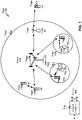
- Fig. 1 is a diagram illustrating a network 100 in which aspects of the present disclosure may be practiced.
- the network 100 may be an LTE network or some other wireless network, such as a 5G or NR network.
- Wireless network 100 may include a number of BSs 110 (shown as BS 110a, BS 110b, BS 110c, and BS 110d) and other network entities.
- a BS is an entity that communicates with user equipment (UEs) and may also be referred to as a base station, a NR BS, a Node B, a gNB, a 5G node B (NB), an access point, a transmit receive point (TRP), and/or the like.
- Each BS may provide communication coverage for a particular geographic area.
- the term "cell" can refer to a coverage area of a BS and/or a BS subsystem serving this coverage area, depending on the context in which the term is used.
- a BS may provide communication coverage for a macro cell, a pico cell, a femto cell, and/or another type of cell.
- a macro cell may cover a relatively large geographic area (e.g., several kilometers in radius) and may allow unrestricted access by UEs with service subscription.
- a pico cell may cover a relatively small geographic area and may allow unrestricted access by UEs with service subscription.
- a femto cell may cover a relatively small geographic area (e.g., a home) and may allow restricted access by UEs having association with the femto cell (e.g., UEs in a closed subscriber group (CSG)).
- a BS for a macro cell may be referred to as a macro BS.
- a BS for a pico cell may be referred to as a pico BS.
- a BS for a femto cell may be referred to as a femto BS or a home BS.
- a BS 110a may be a macro BS for a macro cell 102a
- a BS 110b may be a pico BS for a pico cell 102b
- a BS 110c may be a femto BS for a femto cell 102c.
- a BS may support one or multiple (e.g., three) cells.
- the terms "eNB”, “base station”, “NR BS”, “gNB”, “TRP”, “AP”, “node B", “5G NB”, and “cell” may be used interchangeably herein.
- a cell may not necessarily be stationary, and the geographic area of the cell may move according to the location of a mobile BS.
- the BSs may be interconnected to one another and/or to one or more other BSs or network nodes (not shown) in the access network 100 through various types of backhaul interfaces such as a direct physical connection, a virtual network, and/or the like using any suitable transport network.
- Wireless network 100 may also include relay stations.
- a relay station is an entity that can receive a transmission of data from an upstream station (e.g., a BS or a UE) and send a transmission of the data to a downstream station (e.g., a UE or a BS).
- a relay station may also be a UE that can relay transmissions for other UEs.
- a relay station 110d may communicate with macro BS 110a and a UE 120d in order to facilitate communication between BS 110a and UE 120d.
- a relay station may also be referred to as a relay BS, a relay base station, a relay, etc.
- Wireless network 100 may be a heterogeneous network that includes BSs of different types, e.g., macro BSs, pico BSs, femto BSs, relay BSs, etc. These different types of BSs may have different transmit power levels, different coverage areas, and different impact on interference in wireless network 100.
- macro BSs may have a high transmit power level (e.g., 5 to 40 Watts) whereas pico BSs, femto BSs, and relay BSs may have lower transmit power levels (e.g., 0.1 to 2 Watts).
- a network controller 130 may couple to a set of BSs and may provide coordination and control for these BSs.
- Network controller 130 may communicate with the BSs via a backhaul.
- the BSs may also communicate with one another, e.g., directly or indirectly via a wireless or wireline backhaul.
- UEs 120 may be dispersed throughout wireless network 100, and each UE may be stationary or mobile.
- a UE may also be referred to as an access terminal, a terminal, a mobile station, a subscriber unit, a station, etc.
- a UE may be a cellular phone (e.g., a smart phone), a personal digital assistant (PDA), a wireless modem, a wireless communication device, a handheld device, a laptop computer, a cordless phone, a wireless local loop (WLL) station, a tablet, a camera, a gaming device, a netbook, a smartbook, an ultrabook, medical device or equipment, biometric sensors/devices, wearable devices (smart watches, smart clothing, smart glasses, smart wrist bands, smart jewelry (e.g., smart ring, smart bracelet)), an entertainment device (e.g., a music or video device, or a satellite radio), a vehicular component or sensor, smart meters/sensors, industrial manufacturing equipment, a global positioning system device, or any other suitable device that is configured to communicate via a wireless or wired medium.
- a cellular phone e.g., a smart phone
- PDA personal digital assistant
- WLL wireless local loop
- MTC and eMTC UEs include, for example, robots, drones, remote devices, such as sensors, meters, monitors, location tags, etc., that may communicate with a base station, another device (e.g., remote device), or some other entity.
- a wireless node may provide, for example, connectivity for or to a network (e.g., a wide area network such as Internet or a cellular network) via a wired or wireless communication link.
- Some UEs may be considered Internet-of-Things (IoT) devices, and/or may be implemented as may be implemented as NB-IoT (narrowband internet of things) devices.
- Some UEs may be considered a Customer Premises Equipment (CPE).
- UE 120 may be included inside a housing that houses components of UE 120, such as processor components, memory components, and/or the like.
- any number of wireless networks may be deployed in a given geographic area.
- Each wireless network may support a particular RAT and may operate on one or more frequencies.
- a RAT may also be referred to as a radio technology, an air interface, etc.
- a frequency may also be referred to as a carrier, a frequency channel, etc.
- Each frequency may support a single RAT in a given geographic area in order to avoid interference between wireless networks of different RATs.
- NR or 5G RAT networks may be deployed.
- a scheduling entity e.g., a base station
- the scheduling entity may be responsible for scheduling, assigning, reconfiguring, and releasing resources for one or more subordinate entities. That is, for scheduled communication, subordinate entities utilize resources allocated by the scheduling entity.
- Base stations are not the only entities that may function as a scheduling entity. That is, in some examples, a UE may function as a scheduling entity, scheduling resources for one or more subordinate entities (e.g., one or more other UEs). In this example, the UE is functioning as a scheduling entity, and other UEs utilize resources scheduled by the UE for wireless communication.
- a UE may function as a scheduling entity in a peer-to-peer (P2P) network, and/or in a mesh network. In a mesh network example, UEs may optionally communicate directly with one another in addition to communicating with the scheduling entity.
- P2P peer-to-peer
- mesh network UEs may optionally communicate directly with one another in addition to communicating with the scheduling entity.
- a scheduling entity and one or more subordinate entities may communicate utilizing the scheduled resources.
- two or more UEs 120 may communicate directly using one or more sidelink channels (e.g., without using a base station 110 as an intermediary to communicate with one another).
- the UEs 120 may communicate using peer-to-peer (P2P) communications, device-to-device (D2D) communications, a vehicle-to-everything (V2X) protocol (e.g., which may include a vehicle-to-vehicle (V2V) protocol, a vehicle-to-infrastructure (V2I) protocol, and/or the like), a mesh network, and/or the like).
- V2X vehicle-to-everything
- the UE 120 may perform scheduling operations, resource selection operations, and/or other operations described elsewhere herein as being performed by the base station 110.
- Fig. 1 is provided merely as an example. Other examples are possible and may differ from what was described with regard to Fig. 1 .
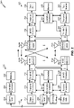
- Fig. 2 shows a block diagram of a design 200 of base station 110 and UE 120, which may be one of the base stations and one of the UEs in Fig. 1 .
- Base station 110 may be equipped with T antennas 234a through 234t
- UE 120 may be equipped with R antennas 252a through 252r, where in general T ⁇ 1 and R ⁇ 1.
- a transmit processor 220 may receive data from a data source 212 for one or more UEs, select one or more modulation and coding schemes (MCS) for each UE based at least in part on channel quality indicators (CQIs) received from the UE, process (e.g., encode and modulate) the data for each UE based at least in part on the MCS(s) selected for the UE, and provide data symbols for all UEs. Transmit processor 220 may also process system information (e.g., for semi-static resource partitioning information (SRPI), etc.) and control information (e.g., CQI requests, grants, upper layer signaling, etc.) and provide overhead symbols and control symbols.
- MCS modulation and coding schemes
- CQIs channel quality indicators
- Transmit processor 220 may also process system information (e.g., for semi-static resource partitioning information (SRPI), etc.) and control information (e.g., CQI requests, grants, upper layer signaling, etc.) and provide overhead symbols
- Transmit processor 220 may also generate reference symbols for reference signals (e.g., the cell-specific reference signal (CRS)) and synchronization signals (e.g., the primary synchronization signal (PSS) and secondary synchronization signal (SSS)).
- a transmit (TX) multiple-input multiple-output (MIMO) processor 230 may perform spatial processing (e.g., precoding) on the data symbols, the control symbols, the overhead symbols, and/or the reference symbols, if applicable, and may provide T output symbol streams to T modulators (MODs) 232a through 232t. Each modulator 232 may process a respective output symbol stream (e.g., for OFDM, etc.) to obtain an output sample stream.
- T modulators modulators
- Each modulator 232 may further process (e.g., convert to analog, amplify, filter, and upconvert) the output sample stream to obtain a downlink signal.
- T downlink signals from modulators 232a through 232t may be transmitted via T antennas 234a through 234t, respectively.
- the synchronization signals can be generated with location encoding to convey additional information.
- antennas 252a through 252r may receive the downlink signals from base station 110 and/or other base stations and may provide received signals to demodulators (DEMODs) 254a through 254r, respectively.
- Each demodulator 254 may condition (e.g., filter, amplify, downconvert, and digitize) a received signal to obtain input samples.
- Each demodulator 254 may further process the input samples (e.g., for OFDM, etc.) to obtain received symbols.
- a MIMO detector 256 may obtain received symbols from all R demodulators 254a through 254r, perform MIMO detection on the received symbols if applicable, and provide detected symbols.
- a receive processor 258 may process (e.g., demodulate and decode) the detected symbols, provide decoded data for UE 120 to a data sink 260, and provide decoded control information and system information to a controller/processor 280.
- a channel processor may determine reference signal received power (RSRP), received signal strength indicator (RSSI), reference signal received quality (RSRQ), channel quality indicator (CQI), etc.
- RSRP reference signal received power
- RSSI received signal strength indicator
- RSRQ reference signal received quality
- CQI channel quality indicator
- one or more components of UE 120 may be included in a housing.
- a transmit processor 264 may receive and process data from a data source 262 and control information (e.g., for reports comprising RSRP, RSSI, RSRQ, CQI, etc.) from controller/processor 280. Transmit processor 264 may also generate reference symbols for one or more reference signals. The symbols from transmit processor 264 may be precoded by a TX MIMO processor 266 if applicable, further processed by modulators 254a through 254r (e.g., for DFT-s-OFDM, CP-OFDM, etc.), and transmitted to base station 110.
- control information e.g., for reports comprising RSRP, RSSI, RSRQ, CQI, etc.
- Transmit processor 264 may also generate reference symbols for one or more reference signals.
- the symbols from transmit processor 264 may be precoded by a TX MIMO processor 266 if applicable, further processed by modulators 254a through 254r (e.g., for DFT-s-OFDM, CP-
- the uplink signals from UE 120 and other UEs may be received by antennas 234, processed by demodulators 232, detected by a MIMO detector 236 if applicable, and further processed by a receive processor 238 to obtain decoded data and control information sent by UE 120.
- Receive processor 238 may provide the decoded data to a data sink 239 and the decoded control information to controller/processor 240.
- Base station 110 may include communication unit 244 and communicate to network controller 130 via communication unit 244.
- Network controller 130 may include communication unit 294, controller/processor 290, and memory 292.
- Controller/processor 240 of base station 110, controller/processor 280 of UE 120, and/or any other component(s) of Fig. 2 may perform one or more techniques associated with using different timing advance values for different numerologies, as described in more detail elsewhere herein.
- controller/processor 240 of base station 110, controller/processor 280 of UE 120, and/or any other component(s) of Fig. 2 may perform or direct operations of, for example, process 900 of Fig. 9 , process 1000 of Fig. 10 , and/or other processes as described herein.
- Memories 242 and 282 may store data and program codes for base station 110 and UE 120, respectively.
- a scheduler 246 may schedule UEs for data transmission on the downlink and/or uplink.
- the stored program codes when executed by processor 280 and/or other processors and modules at UE 120, may cause the UE 120 to perform operations described with respect to process 900 of Fig. 9 and/or other processes as described herein.
- the stored program codes when executed by processor 240 and/or other processors and modules at base station 110, may cause the base station 110 to perform operations described with respect to process 1000 of Fig. 10 and/or other processes as described herein.
- a scheduler 246 may schedule UEs for data transmission on the downlink and/or uplink.
- UE 120 may include means for receiving a timing advance (TA) command that includes a timing value for calculating a timing offset to be applied to adjust a timing of an uplink transmission; means for determining a numerology to be used to calculate the timing offset from the timing value; means for calculating the timing offset using the timing value and the numerology, wherein the timing value corresponds to different timing offsets for different numerologies; and/or the like.
- TA timing advance
- such means may include one or more components of UE 120 described in connection with Fig. 2 .
- base station 110 may include means for determining a numerology to be used to calculate a timing offset to be applied to adjust a timing of an uplink transmission; means for determining a timing value for calculating the timing offset based at least in part on the numerology, wherein different timing values are determined for different numerologies; means for transmitting a timing advance (TA) command that includes the timing value; and/or the like.
- TA timing advance
- such means may include one or more components of base station 110 described in connection with Fig. 2 .
- While blocks in Fig. 2 are illustrated as distinct components, the functions described above with respect to the blocks may be implemented in a single hardware, software, or combination component or in various combinations of components.
- the functions described with respect to the transmit processor 264, the receive processor 258, and/or the TX MIMO processor 266 may be performed by or under the control of processor 280.
- Fig. 2 is provided merely as an example. Other examples are possible and may differ from what was described with regard to Fig. 2 .
- Fig. 3 shows an example frame structure 300 for FDD in a telecommunications system (e.g., NR).
- the transmission timeline for each of the downlink and uplink may be partitioned into units of radio frames (sometimes referred to as frames).
- Each radio frame may have a predetermined duration (e.g., 10 milliseconds (ms)) and may be partitioned into a set of Z (Z ⁇ 1) subframes (e.g., with indices of 0 through Z-1).
- Each subframe may have a predetermined duration (e.g., 1ms) and may include a set of slots (e.g., 2 m slots per subframe are shown in Fig.
- Each slot may include a set of L symbol periods.
- each slot may include fourteen symbol periods (e.g., as shown in Fig. 3 ), seven symbol periods, or another number of symbol periods.
- the subframe may include 2L symbol periods, where the 2L symbol periods in each subframe may be assigned indices of 0 through 2L-1.
- a scheduling unit for the FDD may frame-based, subframe-based, slot-based, symbol-based, and/or the like.
- a wireless communication structure may refer to a periodic time-bounded communication unit defined by a wireless communication standard and/or protocol. Additionally, or alternatively, different configurations of wireless communication structures than those shown in Fig. 3 may be used.
- a base station may transmit synchronization signals.
- a base station may transmit a primary synchronization signal (PSS), a secondary synchronization signal (SSS), and/or the like, on the downlink for each cell supported by the base station.
- PSS and SSS may be used by UEs for cell search and acquisition.
- the PSS may be used by UEs to determine symbol timing
- the SSS may be used by UEs to determine a physical cell identifier, associated with the base station, and frame timing.
- the base station may also transmit a physical broadcast channel (PBCH).
- the PBCH may carry some system information, such as system information that supports initial access by UEs.
- Fig. 3 is provided as an example. Other examples are possible and may differ from what was described with regard to Fig. 3 .
- Fig. 4 shows an example slot format 410 with a normal cyclic prefix.
- the available time frequency resources may be partitioned into resource blocks.
- Each resource block may cover a set to of subcarriers (e.g., 12 subcarriers) in one slot and may include a number of resource elements.
- Each resource element may cover one subcarrier in one symbol period (e.g., in time) and may be used to send one modulation symbol, which may be a real or complex value.
- An interlace structure may be used for each of the downlink and uplink for FDD in certain telecommunications systems (e.g., NR).
- Q interlaces with indices of 0 through Q - 1 may be defined, where Q may be equal to 4, 6, 8, 10, or some other value.
- Each interlace may include slots that are spaced apart by Q frames.
- interlace q may include slots q, q + Q, q + 2Q, etc., where q ⁇ ⁇ 0,...,Q-1 ⁇ .
- a UE may be located within the coverage of multiple BSs. One of these BSs may be selected to serve the UE. The serving BS may be selected based at least in part on various criteria such as received signal strength, received signal quality, path loss, and/or the like. Received signal quality may be quantified by a signal-to-noise-and-interference ratio (SINR), or a reference signal received quality (RSRQ), or some other metric. The UE may operate in a dominant interference scenario in which the UE may observe high interference from one or more interfering BSs.
- SINR signal-to-noise-and-interference ratio
- RSRQ reference signal received quality
- New radio may refer to radios configured to operate according to a new air interface (e.g., other than Orthogonal Frequency Divisional Multiple Access (OFDMA)-based air interfaces) or fixed transport layer (e.g., other than Internet Protocol (IP)).
- OFDM Orthogonal Frequency Divisional Multiple Access
- IP Internet Protocol
- NR may utilize OFDM with a CP (herein referred to as cyclic prefix OFDM or CP-OFDM) and/or SC-FDM on the uplink, may utilize CP-OFDM on the downlink and include support for half-duplex operation using TDD.
- NR may, for example, utilize OFDM with a CP (herein referred to as CP-OFDM) and/or discrete Fourier transform spread orthogonal frequency-division multiplexing (DFT-s-OFDM) on the uplink, may utilize CP-OFDM on the downlink and include support for half-duplex operation using TDD.
- NR may include Enhanced Mobile Broadband (eMBB) service targeting wide bandwidth (e.g., 80 megahertz (MHz) and beyond), millimeter wave (mmW) targeting high carrier frequency (e.g., 60 gigahertz (GHz)), massive MTC (mMTC) targeting non-backward compatible MTC techniques, and/or mission critical targeting ultra reliable low latency communications (URLLC) service.
- eMBB Enhanced Mobile Broadband
- mmW millimeter wave
- mMTC massive MTC
- URLLC ultra reliable low latency communications
- NR resource blocks may span 12 sub-carriers with a sub-carrier bandwidth of 60 or 120 kilohertz (kHz) over a 0.1 millisecond (ms) duration.
- Each radio frame may include 40 slots and may have a length of 10 ms. Consequently, each slot may have a length of 0.25 ms.
- Each slot may indicate a link direction (e.g., DL or UL) for data transmission and the link direction for each slot may be dynamically switched.
- Each slot may include DL/UL data as well as DL/UL control data.
- NR may support a different air interface, other than an OFDM-based interface.
- NR networks may include entities such central units or distributed units.
- Fig. 4 is provided as an example. Other examples are possible and may differ from what was described with regard to Fig. 4 .
- a timing advance (TA) value is used to control a timing of uplink transmissions by a UE (e.g., UE 120 and/or the like) such that the uplink transmissions are received by a base station (e.g., base station 110 and/or the like) at a time that aligns with an internal timing of the base station.
- a UE e.g., UE 120 and/or the like
- a base station e.g., base station 110 and/or the like
- the base station may indicate the TA value to a UE by measuring a time difference between reception of uplink transmissions from the UE and a subframe timing used by the base station (e.g., by determining a difference between when the uplink transmissions were supposed to have been received by the base station, according to the subframe timing, and when the uplink transmissions were actually received), and by transmitting a TA command to instruct the UE to transmit future uplink communications earlier or later to reduce or eliminate the time difference and align timing between the UE and base station.
- the TA command is used to offset timing differences between the UE and the base station due to different propagation delays that occur when the UE is different distances from the base station. If TA commands were not used, then uplink transmissions from different UEs (e.g., located at different distances from the base station) may collide due to mistiming even if the uplink transmissions are scheduled for different subframes.
- the TA command includes a timing value used by the UE to calculate a timing offset for adjusting uplink transmissions.
- the timing value is expressed with a granularity of T S , where the length of time represented by Ts depends on a subcarrier spacing between adjacent carriers, also referred to as a numerology.
- the subcarrier spacing / numerology is fixed at 15 kHz, and as a result, T S always represents the same length of time in LTE, and the UE can calculate the timing offset using this known length of time.
- T S in LTE may be equal to 1 / (FFT Size ⁇ SCS) seconds, where FFT Size represents a size of a Fast Fourier Transform, and where SCS represents a subcarrier spacing.
- this value may be equal to 1 / (2048 ⁇ 15000) seconds, or 1/30720000 seconds.
- the timing value may always have a granularity of 16 ⁇ T S .
- the UE may be configured to operate using different numerologies, such as 15 kHz or 30 kHz for enhanced mobile broadband (eMBB), 30 kHz or 60 kHz for ultra-reliable low latency communications (URLLC), and/or the like. In this case, using a fixed granularity corresponding to 15 kHz may result in timing errors for other numerologies, such as 30 kHz or 60 kHz.
- a resulting time alignment may compromise the cyclic prefix length (e.g., because different numerologies have different cyclic prefix lengths). This may result in poor performance, especially for higher modulation and coding schemes and stringent packet error rate requirements.
- Some techniques and apparatuses described herein relate to determining a timing offset for adjusting a timing of uplink transmissions based on a timing value received in a TA command and a numerology (e.g., a numerology being used for communications between a UE and a base station, a default numerology, and/or the like).
- the same timing value in the TA command may correspond to different timing offsets for different numerologies because the granularity for the timing value is different for different numerologies.
- the base station may determine the timing value to be indicated in the TA command based on the numerology, and the UE may interpret the timing value (e.g., to calculate the timing offset) based on the numerology. In this way, timing errors may be reduced.
- Fig. 5 is a diagram illustrating an example 500 of using different timing advance values for different numerologies, in accordance with various aspects of the present disclosure.
- a base station 110 may determine a numerology to be used to calculate a timing offset to be applied by a UE 120 to adjust a timing of an uplink transmission, and may determine a timing value for calculating the timing offset based at least in part on the numerology.
- the base station 110 may determine different timing values (e.g., to indicate the same timing offset) for different numerologies.
- different numerologies may be associated with different granularities (e.g., representing a different length of time or unit of time) for the timing value.
- the base station 110 may determine a granularity of the timing value based at least in part on the numerology, and may set the timing value to indicate a desired timing offset using the determined granularity.
- a lower numerology e.g., a lower subcarrier spacing
- 15 kHz may be associated with a coarser granularity (e.g., 16 ⁇ T S )
- a higher numerology e.g., a higher subcarrier spacing
- 60 kHz may be associated with a finer granularity (e.g., 4 ⁇ T S ).
- the same timing value e.g., the same sequence of bits
- different timing values e.g., different sequences of bits
- the same granularity for the timing value may be used across multiple cells (e.g., of a single base station 110 or across multiple base stations 110). For example, if the multiple cells are included in the same TA group, and the TA group supports URLLC, then the same granularity may be used for the timing value across those cells. Similarly, if the multiple cells are included in the same TA group, and the TA group does not support URLLC, then the same granularity may be used for the timing value across those cells. In some aspects, a first TA group that supports URLLC may use a different granularity for the timing value than a second TA group that does not support URLLC.
- a service type of eMBB may use a numerology of 15 kHz or 30 kHz (e.g., when URLLC is not configured for the UE 120).
- a service type of URLLC may use a numerology of 30 kHz or 60 kHz (e.g., when URLLC is configured for the UE 120).
- a numerology of 15 kHz may be associated with a coarser granularity than a numerology of 30 kHz and 60 kHz.
- a numerology of 30 kHz may be associated with a finer granularity than a numerology of 15 kHz, and may be associated with a coarser granularity than a numerology of 60 kHz. Additionally, or alternatively, a numerology of 60 kHz may be associated with a finer granularity than a numerology of 15 kHz and 30 kHz. In this way, mistiming may be reduced.
- a base station 110 and/or a UE 120 may support both eMBB and URLLC services.
- the base station 110 and/or the UE 120 may maintain (e.g., store, update, and/or the like) a single TA loop for multiple service types (e.g., eMBB, URLLC, and/or the like), or may maintain separate, independent TA loops for different service types.
- the base station 110 may determine and transmit a single timing value in the TA command, and the UE 120 may use the single timing value to calculate timing offsets for multiple numerologies.
- the UE 120 may use the single timing value to calculate a timing offset for URLLC services (e.g., using a numerology of 30 kHz or 60 kHz) and eMBB services (e.g., using a numerology of 15 kHz or 30 kHz).
- the base station 110 may determine the single timing value using the largest numerology (e.g., the highest numerology) of the multiple numerologies.
- the base station 110 may determine the single timing value using a granularity associated with a numerology used for URLLC services (e.g., rather than eMBB services).
- the UE 120 may then use the single timing value to derive different timing offsets for different numerologies. In this way, timing errors may be reduced for both eMBB services and URLLC services by using a numerology associated with URLLC, which is more sensitive to timing differences.
- the base station 110 may determine and transmit multiple timing values to the UE 120. For example, the base station 110 may determine a first timing value for a first numerology (e.g., using a first granularity corresponding to the first numerology) and a second timing value for a second numerology (e.g., using a second granularity corresponding to the second numerology), and may transmit the first timing value and the second timing value to the UE 120.
- the first timing value and the second timing value may be indicated in the same TA command. In some aspects, the first timing value and the second timing value may be indicated in different TA commands.
- the UE 120 may use the first timing value to calculate a first timing offset for a first numerology, and may use the second timing value to calculate a second timing offset for a second numerology.
- the UE 120 may use the first timing value to calculate a first timing offset for URLLC services (e.g., using a numerology of 30 kHz or 60 kHz), and may use the second timing value to calculate a second timing offset for eMBB services (e.g., using a numerology of 15 kHz or 30 kHz). In this way, timing errors may be reduced for both eMBB services and URLLC services.
- the base station 110 may transmit, and the UE 120 may receive, a TA command that includes the timing value.
- the TA command may be included in a media access control (MAC) control element (CE), as described in more detail below in connection with Fig. 6 .
- the TA command may be included in a random access response (RAR), as described in more detail below in connection with Fig. 7 .
- MAC media access control
- RAR random access response
- the UE 120 may determine a numerology to be used to calculate the timing offset from the timing value.
- the numerology to be used may be indicated in a radio resource control (RRC) message, as described in more detail below in connection with Fig. 6 .
- the numerology to be used may be a default numerology, as described in more detail below in connection with Fig. 7 .
- the UE 120 may calculate a timing offset, to be applied to adjust a timing of an uplink transmission, using the timing value and the numerology.
- the timing value corresponds to different timing offsets for different numerologies.
- different numerologies may correspond to different granularities for the timing value.
- the UE 120 may determine a granularity for the timing value based at least in part on the determined numerology, and may calculate the timing offset using the received timing value and a granularity for the received timing value.
- the UE 120 may transmit, and the base station 110 may receive, an uplink communication.
- the UE 120 may adjust the timing of the uplink transmission (e.g., a time at which the uplink transmission is transmitted) using the timing offset.
- a time difference at the base station 110 between reception of uplink communications from the UE 120 and a subframe timing used by the base station 110 may be reduced or eliminated, and timing between the UE 120 and the base station 110 may be aligned and/or synchronized.
- the likelihood of collision between uplink transmissions from different UEs 120 may be reduced, and interference between such UEs 120 may be reduced or eliminated.
- Fig. 5 is provided as an example. Other examples are possible and may differ from what was described with respect to Fig. 5 .
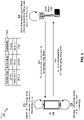
- Fig. 6 is a diagram illustrating an example 600 of using different timing advance values for different numerologies, in accordance with various aspects of the present disclosure.
- a base station 110 may determine a numerology to be used to calculate a timing offset to be applied by a UE 120 to adjust a timing of an uplink transmission, and may determine a timing value for calculating the timing offset based at least in part on the numerology, in a similar manner as described above in connection with Fig. 5 .
- the base station 110 may transmit, and the UE 120 may receive, an RRC message that indicates the numerology.
- the numerology may be a numerology being used for communications between the UE 120 and the base station 110.
- the numerology may be 15 kHz or 30 kHz for eMBB communications between the UE 120 and the base station 110, or may be 30 kHz or 60 kHz for URLLC communications between the UE 120 and the base station 110.
- the base station 110 may transmit, and the UE 120 may receive, a TA command that includes the timing value, in a similar manner as described above in connection with Fig. 5 .
- the TA command may be included in a MAC control element.
- the base station 110 may continue to estimate the timing value, and may send the timing value in a TA command transmitted in a MAC control element if timing correction is required.
- the UE 120 may determine a numerology to be used to calculate the timing offset from the timing value, and may calculate a timing offset, to be applied to adjust a timing of an uplink transmission, using the timing value and the numerology, in a similar manner as described above in connection with Fig. 5 .
- the UE 120 may determine the numerology using the indication in the RRC message.
- the UE 120 may transmit, and the base station 110 may receive, an uplink communication with a timing adjusted using the timing offset, in a similar manner as described above in connection with Fig. 5 .
- a time difference at the base station 110 between reception of uplink communications from the UE 120 and a subframe timing used by the base station 110 may be reduced or eliminated, a timing between the UE 120 and the base station 110 may be aligned and/or synchronized, a likelihood of collision between uplink transmissions from different UEs 120 may be reduced, interference between such UEs 120 may be reduced or eliminated, and/or the like.
- Fig. 6 is provided as an example. Other examples are possible and may differ from what was described with respect to Fig. 6 .
- Fig. 7 is a diagram illustrating an example 700 of using different timing advance values for different numerologies, in accordance with various aspects of the present disclosure.
- a base station 110 may determine a numerology to be used to calculate a timing offset to be applied by a UE 120 to adjust a timing of an uplink transmission, and may determine a timing value for calculating the timing offset based at least in part on the numerology, in a similar manner as described above in connection with Fig. 5 .
- the base station 110 may use a default numerology, such as when an RRC message indicating a numerology has not yet been transmitted to the UE 120.
- the base station 110 and the UE 120 may need to synchronize timing during a random access channel (RACH) procedure, prior to transmission of an RRC message that indicates a numerology negotiated between the UE 120 and the base station 110.
- RACH random access channel
- the UE 120 and the base station 110 may both use a default numerology to permit timing to be aligned.
- the base station 110 may transmit, and the UE 120 may receive, the TA command in a random access response (RAR).
- the numerology may be a default numerology, such as a preconfigured, a hard-coded numerology, a numerology defined according to a 3GPP specification, and/or the like.
- the default numerology may be 15 kHz, 30 kHz, 60 kHz, or the like.
- the base station 110 may estimate an initial timing value based at least in part on a communication received from the UE 120 on a physical random access control channel (PRACH).
- PRACH physical random access control channel
- a PRACH communication may be used as a timing reference during initial access by the UE 120, as part of radio link failure, during a handover, and/or the like.
- the base station 110 may send the TA command in the RAR to the PRACH communication.
- the base station 110 may continue to estimate the timing value, and may send the timing value in a TA command transmitted in a MAC control element if timing correction is required, as described above in connection with Fig. 6 .
- the UE 120 may determine a numerology to be used to calculate the timing offset from the timing value, and may calculate a timing offset, to be applied to adjust a timing of an uplink transmission, using the timing value and the numerology, in a similar manner as described above in connection with Fig. 5 .
- the UE 120 may use a default numerology.
- the UE 120 may transmit, and the base station 110 may receive, an uplink communication with a timing adjusted using the timing offset, in a similar manner as described above in connection with Fig. 5 .
- a time difference at the base station 110 between reception of uplink communications from the UE 120 and a subframe timing used by the base station 110 may be reduced or eliminated, a timing between the UE 120 and the base station 110 may be aligned and/or synchronized, a likelihood of collision between uplink transmissions from different UEs 120 may be reduced, interference between such UEs 120 may be reduced or eliminated, and/or the like.
- Fig. 7 is provided as an example. Other examples are possible and may differ from what was described with respect to Fig. 7 .
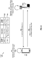
- Fig. 8 is a diagram illustrating an example 800 of using different timing advance values for different numerologies, in accordance with various aspects of the present disclosure.
- a base station 110 may determine a numerology to be used by a UE 120 to calculate a timing offset to be applied by the UE 120 to adjust a timing of an uplink transmission, and may determine a timing value for calculating the timing offset based at least in part on the numerology, in a similar manner as described above in connection with Fig. 5 .
- the timing value may include a set of bits used to calculate the timing offset using a granularity that depends on the numerology, and the set of bits are interpreted as a whole using the granularity.
- the bit sequence 10011 may be interpreted as a whole to represent a value of 19, and that value may be applied to a granularity associated with a numerology.
- a fine granularity of 4 ⁇ T S may be multiplied by the value of 19 to calculate a timing offset for adjusting timing of an uplink communication.
- the timing value includes a first set of bits used to calculate an unadjusted timing offset using a first granularity and a second set of bits used to calculate the timing offset by adjusting the unadjusted timing offset using a second granularity that is finer than the first granularity.
- the bit sequence 10011 may be interpreted as a first set of bits 100 (e.g., the first 3 bits) that represents a first value of 4 and a second set of bits 11 (e.g., the last 2 bits) that represents a second value of 3.
- the first value of 4 may be applied to a first granularity associated with a numerology
- the second value of 3 may be applied to a second granularity associated with the numerology.
- a coarse granularity of 16 ⁇ T S may be multiplied by the first value of 4 to calculate an unadjusted timing offset
- a fine granularity of 4 ⁇ T S may be multiplied by the second value of 3 to calculate an adjustment factor.
- the unadjusted timing offset and the adjustment factor may be added to calculate a timing offset for adjusting timing of an uplink communication.
- the TA command is shown as being 5 bits in length as an example, in practice, the TA command may include a different number of bits, such as 13 bits.
- the first set of bits is shown as being 3 bits in length and the second set of bits is shown as being 2 bits in length, in practice, the first and/or second set of bits may include a different number of bits.
- the first set of bits may include 12 bits, 11 bits, 10 bits, and/or the like, and the second set of bits may include 1 bit, 2 bits, 3 bits, and/or the like.
- a particular set of bits may be configured to represent the adjustment factor, such as the first two bits (e.g., the most significant bits), the last two bits (e.g., the least significant bits), and/or the like.
- the base station 110 may transmit, and the UE 120 may receive, a TA command that includes the timing value, in a similar manner as described above in connection with Figs. 5-7 .
- the UE 120 may determine a numerology to be used to calculate the timing offset from the timing value, and may calculate a timing offset, to be applied to adjust a timing of an uplink transmission, using the timing value and the numerology, in a similar manner as described above in connection with Figs. 5-7 .
- the UE 120 interprets the timing value by applying a first granularity to a first set of bits included in the timing value, and by applying a second granularity to a second set of bits included in the timing value, as described above.
- the base station 110 may indicate, to the UE 120, a configuration for interpreting the timing value (e.g., applying a single granularity or multiple granularities to the bits of the timing value).
- the UE 120 may transmit, and the base station 110 may receive, an uplink communication with a timing adjusted using the timing offset, in a similar manner as described above in connection with Figs. 5-7 .
- a time difference at the base station 110 between reception of uplink communications from the UE 120 and a subframe timing used by the base station 110 may be reduced or eliminated, a timing between the UE 120 and the base station 110 may be aligned and/or synchronized, a likelihood of collision between uplink transmissions from different UEs 120 may be reduced, interference between such UEs 120 may be reduced or eliminated, and/or the like.
- Fig. 8 is provided as an example. Other examples are possible and may differ from what was described with respect to Fig. 8 .
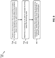
- Fig. 9 is a diagram illustrating an example process 900 performed, for example, by a UE, in accordance with various aspects of the present disclosure.
- Example process 900 is an example where a UE (e.g., UE 120 and/or the like) performs operations associated with using different timing advance values for different numerologies.
- a UE e.g., UE 120 and/or the like
- process 900 may include receiving a timing advance (TA) command that includes a timing value for calculating a timing offset to be applied to adjust a timing of an uplink transmission (block 910).
- TA timing advance
- the UE e.g., using antenna 252, DEMOD 254, MIMO detector 256, receive processor 258, controller/processor 280, and/or the like
- process 900 may include determining a numerology to be used to calculate the timing offset from the timing value (block 920).
- the UE e.g., using controller/processor 280 and/or the like
- process 900 may include calculating the timing offset using the timing value and the numerology, wherein the timing value corresponds to different timing offsets for different numerologies (block 930).
- the UE e.g., using controller/processor 280 and/or the like
- the timing value corresponds to different timing offsets for different numerologies.
- Process 900 may include additional aspects, such as any single aspect or any combination of aspects described below and/or in connection with one or more other processes described elsewhere herein.
- the numerology is 15 kilohertz (kHz) or 30 kHz for enhanced mobile broadband (eMBB) communications or when ultra-reliable low latency communication (URLLC) is not configured for the UE. In some aspects, the numerology is 30 kilohertz (kHz) or 60 kHz when ultra-reliable low latency communication (URLLC) is configured for the UE.
- the TA command is received in a medium access control (MAC) control element.
- the numerology is determined using an indication in a radio resource control (RRC) message when the TA command is received in the MAC control element.
- the numerology is indicated in a radio resource control (RRC) message.
- the numerology is a numerology being used for communications between the UE and a base station.
- the TA command is received in a random access response (RAR) message.
- the numerology is determined using a default numerology when the TA command is received in the RAR message.
- the numerology is a default numerology.
- the timing value is a single timing value used to calculate timing offsets for multiple numerologies.
- the single timing value is determined based at least in part on a largest numerology of the multiple numerologies.
- the single timing value is used to derive different timing offsets for different numerologies.
- the timing value is a first timing value used to calculate a first timing offset for a first numerology, and wherein a second timing value is used to calculate a second timing offset for a second numerology.
- the first timing value and the second timing value are indicated in a same TA command. In some aspects, the first timing value and the second timing value are indicated in different TA commands.
- a granularity of the timing value depends on the numerology. In some aspects, the granularity is the same across multiple cells in a TA group that supports ultra-reliable low latency communication (URLLC). In some aspects, a first TA group that supports ultra-reliable low latency communication (URLLC) uses a different granularity for the timing value than a second TA group that does not support URLLC.
- URLLC ultra-reliable low latency communication
- the timing value is a set of bits used to calculate the timing offset using a granularity that depends on the numerology, wherein the set of bits are interpreted as a whole using the granularity.
- the timing value includes a first set of bits used to calculate an unadjusted timing offset using a first granularity and a second set of bits used to calculate the timing offset by adjusting the unadjusted timing offset using a second granularity that is finer than the first granularity.
- different timing values correspond to a same timing offset for different numerologies.
- the timing of the uplink transmission is adjusted using the timing offset.
- process 900 may include additional blocks, fewer blocks, different blocks, or differently arranged blocks than those depicted in Fig. 9 . Additionally, or alternatively, two or more of the blocks of process 900 may be performed in parallel.
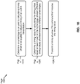
- Fig. 10 is a diagram illustrating an example process 1000 performed, for example, by a base station, in accordance with various aspects of the present disclosure.
- Example process 1000 is an example where a base station (e.g., base station 110 and/or the like) performs operations associated with using different timing advance values for different numerologies.
- a base station e.g., base station 110 and/or the like
- process 1000 may include determining a numerology to be used to calculate a timing offset to be applied to adjust a timing of an uplink transmission (block 1010).
- the base station e.g., using controller/processor 240 and/or the like
- process 1000 may include determining a timing value for calculating the timing offset based at least in part on the numerology, wherein different timing values are determined for different numerologies (block 1020).
- the base station e.g., using controller/processor 240 and/or the like
- different timing values are determined for different numerologies.
- process 1000 may include transmitting a timing advance (TA) command that includes the timing value (block 1030).
- TA timing advance
- the base station e.g., using transmit processor 220, TX MIMO processor 230, controller/processor 240, MOD 232, antenna 234, and/or the like
- Process 1000 may include additional aspects, such as any single aspect or any combination of aspects described below and/or in connection with one or more other processes described elsewhere herein.
- the numerology is 15 kilohertz (kHz) or 30 kHz for enhanced mobile broadband (eMBB) communications or when ultra-reliable low latency communication (URLLC) is not configured. In some aspects, the numerology is 60 kHz when ultra-reliable low latency communication (URLLC) is configured.
- the TA command is transmitted in a medium access control (MAC) control element.
- the numerology is indicated in a radio resource control (RRC) message.
- RRC radio resource control
- the numerology is a numerology being used for communications between a user equipment (UE) and the base station.
- the TA command is transmitted in a random access response (RAR) message.
- the numerology is a default numerology.
- the timing value is a single timing value used to calculate timing offsets for multiple numerologies.
- the single timing value is determined based at least in part on a largest numerology of the multiple numerologies.
- the single timing value is used to derive different timing offsets for different numerologies.
- the timing value is a first timing value used to calculate a first timing offset for a first numerology, and wherein a second timing value is used to calculate a second timing offset for a second numerology.
- the first timing value and the second timing value are indicated in a same TA command. In some aspects, the first timing value and the second timing value are indicated in different TA commands.
- a granularity of the timing value depends on the numerology. In some aspects, the granularity is the same across multiple cells in a TA group that supports ultra-reliable low latency communication (URLLC). In some aspects, a first TA group that supports ultra-reliable low latency communication (URLLC) uses a different granularity for the timing value than a second TA group that does not support URLLC.
- URLLC ultra-reliable low latency communication
- the timing value includes a first set of bits to be used to calculate an unadjusted timing offset using a first granularity and a second set of bits to be used to calculate the timing offset by adjusting the unadjusted timing offset using a second granularity that is finer than the first granularity.
- different timing values correspond to a same timing offset for different numerologies.
- process 1000 may include additional blocks, fewer blocks, different blocks, or differently arranged blocks than those depicted in Fig. 10 . Additionally, or alternatively, two or more of the blocks of process 1000 may be performed in parallel.
- the term component is intended to be broadly construed as hardware, firmware, or a combination of hardware and software.
- a processor is implemented in hardware, firmware, or a combination of hardware and software.
- satisfying a threshold may refer to a value being greater than the threshold, greater than or equal to the threshold, less than the threshold, less than or equal to the threshold, equal to the threshold, not equal to the threshold, and/or the like.
- a phrase referring to "at least one of' a list of items refers to any combination of those items, including single members.
- "at least one of: a, b, or c" is intended to cover a, b, c, a-b, a-c, b-c, and a-b-c, as well as any combination with multiples of the same element (e.g., a-a, a-a-a, a-a-b, a-a-c, a-b-b, a-c-c, b-b, b-b-b, b-b-c, c-c, and c-c-c or any other ordering of a, b, and c).
Landscapes
- Engineering & Computer Science (AREA)
- Signal Processing (AREA)
- Computer Networks & Wireless Communication (AREA)
- Mobile Radio Communication Systems (AREA)
Claims (15)
- Verfahren zur drahtlosen Kommunikation, das von einem Benutzergerät, UE, durchgeführt wird, umfassend:Empfangen (910) eines Timing-Advance-, TA, Befehls, der einen Timing-Wert zum Berechnen eines Timing-Offsets enthält, der angewendet werden soll, um ein Timing einer Uplink-Übertragung anzupassen,wobei der Timing-Wert einen ersten Satz von Bits, die verwendet werden, um einen nicht angepassten Timing-Offset unter Verwendung einer ersten Granularität zu berechnen, und einen zweiten Satz von Bits, die verwendet werden, um den Timing-Offset durch Anpassen des nicht angepassten Timing-Offsets unter Verwendung einer zweiten Granularität, die feiner als die erste Granularität ist, zu berechnen, enthält;Bestimmen (920) einer Numerologie, die verwendet werden soll, um den Timing-Offset aus dem Timing-Wert zu berechnen;Berechnen (930) des Timing-Offsets unter Verwendung des Timing-Werts und der Numerologie, wobei der Timing-Wert verschiedenen Timing-Offsets für verschiedene Numerologien entspricht, undÜbertragen der Uplink-Übertragung, wobei das Timing der Uplink-Übertragung unter Verwendung des Timing-Offsets angepasst wird.
- Verfahren nach Anspruch 1, wobei die Numerologie 15 Kilohertz, kHz oder 30 kHz für verbesserte mobile Breitband-, eMBB-, Kommunikationen beträgt oder wenn ultrazuverlässige Kommunikation mit niedriger Latenz, URLLC, nicht für das UE konfiguriert ist, oder wobei die Numerologie 30 kHz oder 60 kHz beträgt, wenn URLLC für das UE konfiguriert ist.
- Verfahren nach Anspruch 1, wobei der TA-Befehl in einem Medium Access Control-, MAC, Steuerelement empfangen wird; und vorzugsweisewobei die Numerologie unter Verwendung einer Angabe in einer Radio Resource Control-, RRC, Nachricht bestimmt wird, wenn der TA-Befehl im MAC-Steuerelement empfangen wird; und ferner vorzugsweisewobei die Numerologie in einer Radio Resource Control-, RRC, Nachricht angegeben wird.
- Verfahren nach Anspruch 1, wobei der TA-Befehl in einer Random Access Response-, RAR, Nachricht empfangen wird; und vorzugsweisewobei die Numerologie unter Verwendung einer Standardnumerologie bestimmt wird, wenn der TA-Befehl in der RAR-Nachricht empfangen wird; und ferner vorzugsweisewobei die Numerologie eine Standardnumerologie ist.
- Verfahren nach Anspruch 1, wobei der Timing-Wert ein erster Timing-Wert ist, der verwendet wird, um einen ersten Timing-Offset für eine erste Numerologie zu berechnen, und
wobei ein zweiter Timing-Wert verwendet wird, um einen zweiten Timing-Offset für eine zweite Numerologie zu berechnen. - Verfahren nach Anspruch 1, wobei eine Granularität des Timing-Werts von der Numerologie abhängt; und vorzugsweise
wobei die Granularität über mehrere Zellen in einer ersten TA-Gruppe gleich ist, die ultrazuverlässige Kommunikation mit niedriger Latenz, URLLC, unterstützt. - Verfahren nach Anspruch 1, wobei eine erste TA-Gruppe, die ultrazuverlässige Kommunikation mit niedriger Latenz, URLLC, unterstützt, eine andere Granularität für den Timing-Wert verwendet als eine zweite TA-Gruppe, die URLLC nicht unterstützt.
- Verfahren zur drahtlosen Kommunikation, das von einer Basisstation durchgeführt wird, umfassend:Bestimmen (1010) einer Numerologie, die verwendet werden soll, um einen Timing-Offset zu berechnen, der angewendet werden soll, um ein Timing einer Uplink-Übertragung anzupassen;Bestimmen (1020) eines Timing-Werts zum Berechnen des Timing-Offsets basierend zumindest teilweise auf der Numerologie, wobei verschiedene Timing-Werte für verschiedene Numerologien bestimmt werden;Übertragen (1030) eines Timing-Advance-, TA, Befehls, der den Timing-Wert enthält,wobei der Timing-Wert einen ersten Satz von Bits, die verwendet werden sollen, um einen nicht angepassten Timing-Offset unter Verwendung einer ersten Granularität zu berechnen, und einen zweiten Satz von Bits, die verwendet werden sollen, um den Timing-Offset durch Anpassen des nicht angepassten Timing-Offsets unter Verwendung einer zweiten Granularität, die feiner als die erste Granularität ist, zu berechnen, enthält; undEmpfangen der Uplink-Übertragung.
- Verfahren nach Anspruch 8, wobei der TA-Befehl in einem Medium Access Control-, MAC, Steuerelement übertragen wird, und wobei die Numerologie in einer Radio Resource Control-, RRC, Nachricht angegeben wird.
- Verfahren nach Anspruch 8, wobei der TA-Befehl in einer Random Access Response-, RAR, Nachricht übertragen wird, und wobei die Numerologie eine Standardnumerologie ist.
- Verfahren nach Anspruch 8, wobei der Timing-Wert ein erster Timing-Wert ist, der verwendet wird, um einen ersten Timing-Offset für eine erste Numerologie zu berechnen, und
wobei ein zweiter Timing-Wert verwendet wird, um einen zweiten Timing-Offset für eine zweite Numerologie zu berechnen. - Verfahren nach Anspruch 8, wobei eine Granularität des Timing-Werts von der Numerologie abhängt; und vorzugsweise
wobei die Granularität über mehrere Zellen in einer TA-Gruppe gleich ist, die ultrazuverlässige Kommunikation mit niedriger Latenz, URLLC, unterstützt. - Verfahren nach Anspruch 8, wobei eine erste TA-Gruppe, die ultrazuverlässige Kommunikation mit niedriger Latenz, URLLC, unterstützt, eine andere Granularität für den Timing-Wert verwendet als eine zweite TA-Gruppe, die URLLC nicht unterstützt.
- Benutzergerät, UE, (120) zur drahtlosen Kommunikation, umfassend:Speicher (282); undeinen oder mehrere Prozessoren (280), die operativ mit dem Speicher gekoppelt sind, wobei der Speicher und der eine oder die mehreren Prozessoren konfiguriert sind zum:Empfangen eines Timing-Advance-, TA, Befehls, der einen Timing-Wert zum Berechnen eines Timing-Offsets enthält, der angewendet werden soll, um ein Timing einer Uplink-Übertragung anzupassen,wobei der Timing-Wert einen ersten Satz von Bits, die verwendet werden, um einen nicht angepassten Timing-Offset unter Verwendung einer ersten Granularität zu berechnen, und einen zweiten Satz von Bits, die verwendet werden, um den Timing-Offset durch Anpassen des nicht angepassten Timing-Offsets unter Verwendung einer zweiten Granularität, die feiner als die erste Granularität ist, zu berechnen, enthält;Bestimmen einer Numerologie, die verwendet werden soll, um den Timing-Offset aus dem Timing-Wert zu berechnen; undBerechnen des Timing-Offsets unter Verwendung des Timing-Werts und der Numerologie, wobei der Timing-Wert verschiedenen Timing-Offsets für verschiedene Numerologien entspricht; undÜbertragen der Uplink-Übertragung, wobei das Timing der Uplink-Übertragung unter Verwendung des Timing-Offsets angepasst wird.
- Basisstation (110) zur drahtlosen Kommunikation, umfassend:Speicher (242); undeinen oder mehrere Prozessoren (240), die operativ mit dem Speicher gekoppelt sind, wobei der Speicher und der eine oder die mehreren Prozessoren konfiguriert sind zum:Bestimmen einer Numerologie, die verwendet werden soll, um einen Timing-Offset zu berechnen, der angewendet werden soll, um ein Timing einer Uplink-Übertragung anzupassen;Bestimmen eines Timing-Werts zum Berechnen des Timing-Offsets basierend zumindest teilweise auf der Numerologie, wobei verschiedene Timing-Werte für verschiedene Numerologien bestimmt werden;Übertragen eines Timing-Advance-, TA, Befehls, der den Timing-Wert enthält,wobei der Timing-Wert einen ersten Satz von Bits, die verwendet werden sollen, um einen nicht angepassten Timing-Offset unter Verwendung einer ersten Granularität zu berechnen, und einen zweiten Satz von Bits, die verwendet werden sollen, um den Timing-Offset durch Anpassen des nicht angepassten Timing-Offsets unter Verwendung einer zweiten Granularität, die feiner als die erste Granularität ist, zu berechnen, enthält; undEmpfangen der Uplink-Übertragung.
Applications Claiming Priority (2)
| Application Number | Priority Date | Filing Date | Title |
|---|---|---|---|
| US16/024,417 US10813069B2 (en) | 2018-06-29 | 2018-06-29 | Techniques and apparatuses for using different timing advance values for different numerologies |
| PCT/US2019/037273 WO2020005586A1 (en) | 2018-06-29 | 2019-06-14 | Techniques and apparatuses for using different timing advance values for different numerologies |
Publications (2)
| Publication Number | Publication Date |
|---|---|
| EP3815436A1 EP3815436A1 (de) | 2021-05-05 |
| EP3815436B1 true EP3815436B1 (de) | 2022-10-26 |
Family
ID=67108224
Family Applications (1)
| Application Number | Title | Priority Date | Filing Date |
|---|---|---|---|
| EP19734645.5A Active EP3815436B1 (de) | 2018-06-29 | 2019-06-14 | Verfahren und vorrichtungen zur verwendung von unterschiedlichen zeitvorlaufswerten für verschiedene numerologien |
Country Status (4)
| Country | Link |
|---|---|
| US (1) | US10813069B2 (de) |
| EP (1) | EP3815436B1 (de) |
| CN (1) | CN112314018B (de) |
| WO (1) | WO2020005586A1 (de) |
Families Citing this family (8)
| Publication number | Priority date | Publication date | Assignee | Title |
|---|---|---|---|---|
| US11411779B2 (en) | 2020-03-31 | 2022-08-09 | XCOM Labs, Inc. | Reference signal channel estimation |
| CN118612838A (zh) * | 2020-05-20 | 2024-09-06 | 高通股份有限公司 | 用于多面板天线上行链路传输的因面板而异的定时偏移 |
| US12432676B2 (en) | 2020-05-29 | 2025-09-30 | Qualcomm Incorporated | Timing advance indication for multi-panel uplink transmission |
| CN114071690B (zh) * | 2020-08-06 | 2024-04-26 | 维沃移动通信有限公司 | 信息上报方法、信息接收方法及相关设备 |
| CA3195885A1 (en) | 2020-10-19 | 2022-04-28 | XCOM Labs, Inc. | Reference signal for wireless communication systems |
| WO2022093988A1 (en) | 2020-10-30 | 2022-05-05 | XCOM Labs, Inc. | Clustering and/or rate selection in multiple-input multiple-output communication systems |
| WO2022241436A1 (en) | 2021-05-14 | 2022-11-17 | XCOM Labs, Inc. | Scrambling identifiers for wireless communication systems |
| CN117581601A (zh) | 2021-08-06 | 2024-02-20 | 中兴通讯股份有限公司 | 无线通信中的反馈定时确定方案 |
Family Cites Families (10)
| Publication number | Priority date | Publication date | Assignee | Title |
|---|---|---|---|---|
| US10200170B2 (en) | 2016-03-09 | 2019-02-05 | Samsung Electronics Co., Ltd. | Method and apparatus for a multi-cell full-dimension MIMO system |
| US10630410B2 (en) | 2016-05-13 | 2020-04-21 | Telefonaktiebolaget Lm Ericsson (Publ) | Network architecture, methods, and devices for a wireless communications network |
| AU2017284729B2 (en) | 2016-06-15 | 2020-03-05 | Lg Electronics Inc. | Method and apparatus for transmitting and receiving wireless signal in wireless communication system |
| CN107872417B (zh) | 2016-09-28 | 2022-03-01 | 中兴通讯股份有限公司 | 数据发送、接收方法及装置 |
| ES2920144T3 (es) | 2016-09-30 | 2022-08-01 | Ericsson Telefon Ab L M | Ajuste de temporización autónomo para un dispositivo inalámbrico |
| EP3301986A1 (de) * | 2016-09-30 | 2018-04-04 | Panasonic Intellectual Property Corporation of America | Verbesserte uplink-ressourcenzuweisung zwischen verschiedenen ofdm-numerologieschemen |
| CN109275185B (zh) * | 2017-06-06 | 2020-03-20 | 华为技术有限公司 | 发送上行信息的方法和装置 |
| CN116709494A (zh) * | 2017-08-10 | 2023-09-05 | 三星电子株式会社 | 用于确定上行链路发送定时的方法和装置 |
| CN111165061B (zh) * | 2017-09-29 | 2023-11-24 | 三星电子株式会社 | 无线通信系统中处理用于随机接入信道过程的带宽部分配置的装置和方法 |
| US10728887B2 (en) * | 2017-11-14 | 2020-07-28 | Lenovo (Singapore) Pte Ltd | Downlink control for ultra reliable communications |
-
2018
- 2018-06-29 US US16/024,417 patent/US10813069B2/en active Active
-
2019
- 2019-06-14 EP EP19734645.5A patent/EP3815436B1/de active Active
- 2019-06-14 WO PCT/US2019/037273 patent/WO2020005586A1/en not_active Ceased
- 2019-06-14 CN CN201980043313.6A patent/CN112314018B/zh active Active
Also Published As
| Publication number | Publication date |
|---|---|
| US10813069B2 (en) | 2020-10-20 |
| CN112314018B (zh) | 2024-02-20 |
| EP3815436A1 (de) | 2021-05-05 |
| WO2020005586A1 (en) | 2020-01-02 |
| CN112314018A (zh) | 2021-02-02 |
| US20200008239A1 (en) | 2020-01-02 |
Similar Documents
| Publication | Publication Date | Title |
|---|---|---|
| EP4022951B1 (de) | Anzeige einer benutzergerätefähigkeit für verbundungsübergreifende interferenzmessung | |
| US12232092B2 (en) | Techniques and apparatuses for variable timing adjustment granularity | |
| EP3714570B1 (de) | Bandbreitenteilsignalisierung und -umschaltung | |
| US11950212B2 (en) | Timing advance signaling for multi-transmit receive point operation | |
| EP3776988B1 (de) | Meldung von kanalqualitätsindikatoren (cqi) für extrem zuverlässige kommunikation mit niedriger latenz (urllc) | |
| EP3931990B1 (de) | Verfahren und vorrichtung zur vernetzungsinterferenzmessung und -meldung | |
| EP3857957B1 (de) | Sendeparameterregelung | |
| EP3815436B1 (de) | Verfahren und vorrichtungen zur verwendung von unterschiedlichen zeitvorlaufswerten für verschiedene numerologien | |
| US11368956B2 (en) | Radio link management under bandwidth part switching | |
| US12213074B2 (en) | Secondary cell dormancy using dormancy profile | |
| EP3718238B1 (de) | Trägerinformationssignalisierung in einem 5g-netzwerk | |
| EP4052384A1 (de) | Strahlauswahl für kommunikation beim einsatz eines multisendeempfangspunktes | |
| EP3841817B1 (de) | Kollisionshandhabung für eine physikalische uplink-kanalwiederholung | |
| US10873416B2 (en) | Techniques and apparatuses for determining uplink transmission timelines related to a channel state information reference signal (CSI-RS) | |
| US12532311B2 (en) | Sounding reference signal resource determination for physical uplink shared channel with configured grant | |
| WO2020163987A1 (en) | Differential reporting mode for amplitude and/or co-phase | |
| US20210126693A1 (en) | Indicating beam failure for multiple cells | |
| US10886995B2 (en) | Beam management signaling | |
| EP3811712B1 (de) | Kollisionsverwaltung | |
| WO2020205772A1 (en) | Indication design and signaling | |
| EP3824581B1 (de) | Zugang zu höher liegenden frequenzbändern | |
| WO2021142762A1 (en) | Hopping pattern for cross bandwidth part frequency hopping | |
| WO2020258132A1 (en) | Csi reporting for partial reciprocity | |
| WO2019200608A1 (en) | Techniques and apparatuses for numerology signaling |
Legal Events
| Date | Code | Title | Description |
|---|---|---|---|
| STAA | Information on the status of an ep patent application or granted ep patent |
Free format text: STATUS: UNKNOWN |
|
| STAA | Information on the status of an ep patent application or granted ep patent |
Free format text: STATUS: THE INTERNATIONAL PUBLICATION HAS BEEN MADE |
|
| PUAI | Public reference made under article 153(3) epc to a published international application that has entered the european phase |
Free format text: ORIGINAL CODE: 0009012 |
|
| STAA | Information on the status of an ep patent application or granted ep patent |
Free format text: STATUS: REQUEST FOR EXAMINATION WAS MADE |
|
| 17P | Request for examination filed |
Effective date: 20201119 |
|
| AK | Designated contracting states |
Kind code of ref document: A1 Designated state(s): AL AT BE BG CH CY CZ DE DK EE ES FI FR GB GR HR HU IE IS IT LI LT LU LV MC MK MT NL NO PL PT RO RS SE SI SK SM TR |
|
| DAV | Request for validation of the european patent (deleted) | ||
| DAX | Request for extension of the european patent (deleted) | ||
| GRAP | Despatch of communication of intention to grant a patent |
Free format text: ORIGINAL CODE: EPIDOSNIGR1 |
|
| STAA | Information on the status of an ep patent application or granted ep patent |
Free format text: STATUS: GRANT OF PATENT IS INTENDED |
|
| INTG | Intention to grant announced |
Effective date: 20220517 |
|
| GRAS | Grant fee paid |
Free format text: ORIGINAL CODE: EPIDOSNIGR3 |
|
| GRAA | (expected) grant |
Free format text: ORIGINAL CODE: 0009210 |
|
| STAA | Information on the status of an ep patent application or granted ep patent |
Free format text: STATUS: THE PATENT HAS BEEN GRANTED |
|
| AK | Designated contracting states |
Kind code of ref document: B1 Designated state(s): AL AT BE BG CH CY CZ DE DK EE ES FI FR GB GR HR HU IE IS IT LI LT LU LV MC MK MT NL NO PL PT RO RS SE SI SK SM TR |
|
| REG | Reference to a national code |
Ref country code: GB Ref legal event code: FG4D |
|
| REG | Reference to a national code |
Ref country code: CH Ref legal event code: EP |
|
| REG | Reference to a national code |
Ref country code: DE Ref legal event code: R096 Ref document number: 602019021130 Country of ref document: DE |
|
| REG | Reference to a national code |
Ref country code: AT Ref legal event code: REF Ref document number: 1528009 Country of ref document: AT Kind code of ref document: T Effective date: 20221115 |
|
| REG | Reference to a national code |
Ref country code: IE Ref legal event code: FG4D |
|
| REG | Reference to a national code |
Ref country code: LT Ref legal event code: MG9D |
|
| REG | Reference to a national code |
Ref country code: NL Ref legal event code: MP Effective date: 20221026 |
|
| REG | Reference to a national code |
Ref country code: AT Ref legal event code: MK05 Ref document number: 1528009 Country of ref document: AT Kind code of ref document: T Effective date: 20221026 |
|
| PG25 | Lapsed in a contracting state [announced via postgrant information from national office to epo] |
Ref country code: NL Free format text: LAPSE BECAUSE OF FAILURE TO SUBMIT A TRANSLATION OF THE DESCRIPTION OR TO PAY THE FEE WITHIN THE PRESCRIBED TIME-LIMIT Effective date: 20221026 |
|
| PG25 | Lapsed in a contracting state [announced via postgrant information from national office to epo] |
Ref country code: SE Free format text: LAPSE BECAUSE OF FAILURE TO SUBMIT A TRANSLATION OF THE DESCRIPTION OR TO PAY THE FEE WITHIN THE PRESCRIBED TIME-LIMIT Effective date: 20221026 Ref country code: PT Free format text: LAPSE BECAUSE OF FAILURE TO SUBMIT A TRANSLATION OF THE DESCRIPTION OR TO PAY THE FEE WITHIN THE PRESCRIBED TIME-LIMIT Effective date: 20230227 Ref country code: NO Free format text: LAPSE BECAUSE OF FAILURE TO SUBMIT A TRANSLATION OF THE DESCRIPTION OR TO PAY THE FEE WITHIN THE PRESCRIBED TIME-LIMIT Effective date: 20230126 Ref country code: LT Free format text: LAPSE BECAUSE OF FAILURE TO SUBMIT A TRANSLATION OF THE DESCRIPTION OR TO PAY THE FEE WITHIN THE PRESCRIBED TIME-LIMIT Effective date: 20221026 Ref country code: FI Free format text: LAPSE BECAUSE OF FAILURE TO SUBMIT A TRANSLATION OF THE DESCRIPTION OR TO PAY THE FEE WITHIN THE PRESCRIBED TIME-LIMIT Effective date: 20221026 Ref country code: ES Free format text: LAPSE BECAUSE OF FAILURE TO SUBMIT A TRANSLATION OF THE DESCRIPTION OR TO PAY THE FEE WITHIN THE PRESCRIBED TIME-LIMIT Effective date: 20221026 Ref country code: AT Free format text: LAPSE BECAUSE OF FAILURE TO SUBMIT A TRANSLATION OF THE DESCRIPTION OR TO PAY THE FEE WITHIN THE PRESCRIBED TIME-LIMIT Effective date: 20221026 |
|
| PG25 | Lapsed in a contracting state [announced via postgrant information from national office to epo] |
Ref country code: RS Free format text: LAPSE BECAUSE OF FAILURE TO SUBMIT A TRANSLATION OF THE DESCRIPTION OR TO PAY THE FEE WITHIN THE PRESCRIBED TIME-LIMIT Effective date: 20221026 Ref country code: PL Free format text: LAPSE BECAUSE OF FAILURE TO SUBMIT A TRANSLATION OF THE DESCRIPTION OR TO PAY THE FEE WITHIN THE PRESCRIBED TIME-LIMIT Effective date: 20221026 Ref country code: LV Free format text: LAPSE BECAUSE OF FAILURE TO SUBMIT A TRANSLATION OF THE DESCRIPTION OR TO PAY THE FEE WITHIN THE PRESCRIBED TIME-LIMIT Effective date: 20221026 Ref country code: IS Free format text: LAPSE BECAUSE OF FAILURE TO SUBMIT A TRANSLATION OF THE DESCRIPTION OR TO PAY THE FEE WITHIN THE PRESCRIBED TIME-LIMIT Effective date: 20230226 Ref country code: HR Free format text: LAPSE BECAUSE OF FAILURE TO SUBMIT A TRANSLATION OF THE DESCRIPTION OR TO PAY THE FEE WITHIN THE PRESCRIBED TIME-LIMIT Effective date: 20221026 Ref country code: GR Free format text: LAPSE BECAUSE OF FAILURE TO SUBMIT A TRANSLATION OF THE DESCRIPTION OR TO PAY THE FEE WITHIN THE PRESCRIBED TIME-LIMIT Effective date: 20230127 |
|
| REG | Reference to a national code |
Ref country code: DE Ref legal event code: R097 Ref document number: 602019021130 Country of ref document: DE |
|
| PG25 | Lapsed in a contracting state [announced via postgrant information from national office to epo] |
Ref country code: SM Free format text: LAPSE BECAUSE OF FAILURE TO SUBMIT A TRANSLATION OF THE DESCRIPTION OR TO PAY THE FEE WITHIN THE PRESCRIBED TIME-LIMIT Effective date: 20221026 Ref country code: RO Free format text: LAPSE BECAUSE OF FAILURE TO SUBMIT A TRANSLATION OF THE DESCRIPTION OR TO PAY THE FEE WITHIN THE PRESCRIBED TIME-LIMIT Effective date: 20221026 Ref country code: EE Free format text: LAPSE BECAUSE OF FAILURE TO SUBMIT A TRANSLATION OF THE DESCRIPTION OR TO PAY THE FEE WITHIN THE PRESCRIBED TIME-LIMIT Effective date: 20221026 Ref country code: DK Free format text: LAPSE BECAUSE OF FAILURE TO SUBMIT A TRANSLATION OF THE DESCRIPTION OR TO PAY THE FEE WITHIN THE PRESCRIBED TIME-LIMIT Effective date: 20221026 Ref country code: CZ Free format text: LAPSE BECAUSE OF FAILURE TO SUBMIT A TRANSLATION OF THE DESCRIPTION OR TO PAY THE FEE WITHIN THE PRESCRIBED TIME-LIMIT Effective date: 20221026 |
|
| PG25 | Lapsed in a contracting state [announced via postgrant information from national office to epo] |
Ref country code: SK Free format text: LAPSE BECAUSE OF FAILURE TO SUBMIT A TRANSLATION OF THE DESCRIPTION OR TO PAY THE FEE WITHIN THE PRESCRIBED TIME-LIMIT Effective date: 20221026 Ref country code: AL Free format text: LAPSE BECAUSE OF FAILURE TO SUBMIT A TRANSLATION OF THE DESCRIPTION OR TO PAY THE FEE WITHIN THE PRESCRIBED TIME-LIMIT Effective date: 20221026 |
|
| PLBE | No opposition filed within time limit |
Free format text: ORIGINAL CODE: 0009261 |
|
| STAA | Information on the status of an ep patent application or granted ep patent |
Free format text: STATUS: NO OPPOSITION FILED WITHIN TIME LIMIT |
|
| 26N | No opposition filed |
Effective date: 20230727 |
|
| PG25 | Lapsed in a contracting state [announced via postgrant information from national office to epo] |
Ref country code: SI Free format text: LAPSE BECAUSE OF FAILURE TO SUBMIT A TRANSLATION OF THE DESCRIPTION OR TO PAY THE FEE WITHIN THE PRESCRIBED TIME-LIMIT Effective date: 20221026 |
|
| PG25 | Lapsed in a contracting state [announced via postgrant information from national office to epo] |
Ref country code: MC Free format text: LAPSE BECAUSE OF FAILURE TO SUBMIT A TRANSLATION OF THE DESCRIPTION OR TO PAY THE FEE WITHIN THE PRESCRIBED TIME-LIMIT Effective date: 20221026 |
|
| PG25 | Lapsed in a contracting state [announced via postgrant information from national office to epo] |
Ref country code: MC Free format text: LAPSE BECAUSE OF FAILURE TO SUBMIT A TRANSLATION OF THE DESCRIPTION OR TO PAY THE FEE WITHIN THE PRESCRIBED TIME-LIMIT Effective date: 20221026 |
|
| REG | Reference to a national code |
Ref country code: CH Ref legal event code: PL |
|
| REG | Reference to a national code |
Ref country code: BE Ref legal event code: MM Effective date: 20230630 |
|
| PG25 | Lapsed in a contracting state [announced via postgrant information from national office to epo] |
Ref country code: LU Free format text: LAPSE BECAUSE OF NON-PAYMENT OF DUE FEES Effective date: 20230614 |
|
| REG | Reference to a national code |
Ref country code: IE Ref legal event code: MM4A |
|
| PG25 | Lapsed in a contracting state [announced via postgrant information from national office to epo] |
Ref country code: LU Free format text: LAPSE BECAUSE OF NON-PAYMENT OF DUE FEES Effective date: 20230614 |
|
| PG25 | Lapsed in a contracting state [announced via postgrant information from national office to epo] |
Ref country code: IE Free format text: LAPSE BECAUSE OF NON-PAYMENT OF DUE FEES Effective date: 20230614 |
|
| PG25 | Lapsed in a contracting state [announced via postgrant information from national office to epo] |
Ref country code: IE Free format text: LAPSE BECAUSE OF NON-PAYMENT OF DUE FEES Effective date: 20230614 Ref country code: CH Free format text: LAPSE BECAUSE OF NON-PAYMENT OF DUE FEES Effective date: 20230630 |
|
| PG25 | Lapsed in a contracting state [announced via postgrant information from national office to epo] |
Ref country code: IT Free format text: LAPSE BECAUSE OF FAILURE TO SUBMIT A TRANSLATION OF THE DESCRIPTION OR TO PAY THE FEE WITHIN THE PRESCRIBED TIME-LIMIT Effective date: 20221026 Ref country code: BE Free format text: LAPSE BECAUSE OF NON-PAYMENT OF DUE FEES Effective date: 20230630 |
|
| PG25 | Lapsed in a contracting state [announced via postgrant information from national office to epo] |
Ref country code: BG Free format text: LAPSE BECAUSE OF FAILURE TO SUBMIT A TRANSLATION OF THE DESCRIPTION OR TO PAY THE FEE WITHIN THE PRESCRIBED TIME-LIMIT Effective date: 20221026 |
|
| PG25 | Lapsed in a contracting state [announced via postgrant information from national office to epo] |
Ref country code: BG Free format text: LAPSE BECAUSE OF FAILURE TO SUBMIT A TRANSLATION OF THE DESCRIPTION OR TO PAY THE FEE WITHIN THE PRESCRIBED TIME-LIMIT Effective date: 20221026 |
|
| PGFP | Annual fee paid to national office [announced via postgrant information from national office to epo] |
Ref country code: DE Payment date: 20250509 Year of fee payment: 7 |
|
| PGFP | Annual fee paid to national office [announced via postgrant information from national office to epo] |
Ref country code: GB Payment date: 20250508 Year of fee payment: 7 |
|
| PGFP | Annual fee paid to national office [announced via postgrant information from national office to epo] |
Ref country code: FR Payment date: 20250512 Year of fee payment: 7 |
|
| PG25 | Lapsed in a contracting state [announced via postgrant information from national office to epo] |
Ref country code: CY Free format text: LAPSE BECAUSE OF FAILURE TO SUBMIT A TRANSLATION OF THE DESCRIPTION OR TO PAY THE FEE WITHIN THE PRESCRIBED TIME-LIMIT; INVALID AB INITIO Effective date: 20190614 |
|
| PG25 | Lapsed in a contracting state [announced via postgrant information from national office to epo] |
Ref country code: HU Free format text: LAPSE BECAUSE OF FAILURE TO SUBMIT A TRANSLATION OF THE DESCRIPTION OR TO PAY THE FEE WITHIN THE PRESCRIBED TIME-LIMIT; INVALID AB INITIO Effective date: 20190614 |
|
| PG25 | Lapsed in a contracting state [announced via postgrant information from national office to epo] |
Ref country code: TR Free format text: LAPSE BECAUSE OF FAILURE TO SUBMIT A TRANSLATION OF THE DESCRIPTION OR TO PAY THE FEE WITHIN THE PRESCRIBED TIME-LIMIT Effective date: 20221026 |