EP3815533B1 - Knetmaschine für nahrungsmittelteige mit einer abdeckung mit schnellverschluss - Google Patents
Knetmaschine für nahrungsmittelteige mit einer abdeckung mit schnellverschluss Download PDFInfo
- Publication number
- EP3815533B1 EP3815533B1 EP19205818.8A EP19205818A EP3815533B1 EP 3815533 B1 EP3815533 B1 EP 3815533B1 EP 19205818 A EP19205818 A EP 19205818A EP 3815533 B1 EP3815533 B1 EP 3815533B1
- Authority
- EP
- European Patent Office
- Prior art keywords
- kneading machine
- cover
- kneading
- machine according
- machine frame
- Prior art date
- Legal status (The legal status is an assumption and is not a legal conclusion. Google has not performed a legal analysis and makes no representation as to the accuracy of the status listed.)
- Active
Links
Images
Classifications
-
- A—HUMAN NECESSITIES
- A21—BAKING; EDIBLE DOUGHS
- A21C—MACHINES OR EQUIPMENT FOR MAKING OR PROCESSING DOUGHS; HANDLING BAKED ARTICLES MADE FROM DOUGH
- A21C1/00—Mixing or kneading machines for the preparation of dough
- A21C1/14—Structural elements of mixing or kneading machines; Parts; Accessories
- A21C1/1485—Doors; Closures; Operating, e.g. safety, mechanisms therefor
-
- A—HUMAN NECESSITIES
- A21—BAKING; EDIBLE DOUGHS
- A21C—MACHINES OR EQUIPMENT FOR MAKING OR PROCESSING DOUGHS; HANDLING BAKED ARTICLES MADE FROM DOUGH
- A21C1/00—Mixing or kneading machines for the preparation of dough
- A21C1/02—Mixing or kneading machines for the preparation of dough with vertically-mounted tools; Machines for whipping or beating
-
- A—HUMAN NECESSITIES
- A21—BAKING; EDIBLE DOUGHS
- A21C—MACHINES OR EQUIPMENT FOR MAKING OR PROCESSING DOUGHS; HANDLING BAKED ARTICLES MADE FROM DOUGH
- A21C1/00—Mixing or kneading machines for the preparation of dough
- A21C1/14—Structural elements of mixing or kneading machines; Parts; Accessories
- A21C1/148—Safety arrangements
-
- B—PERFORMING OPERATIONS; TRANSPORTING
- B01—PHYSICAL OR CHEMICAL PROCESSES OR APPARATUS IN GENERAL
- B01F—MIXING, e.g. DISSOLVING, EMULSIFYING OR DISPERSING
- B01F27/00—Mixers with rotary stirring devices in fixed receptacles; Kneaders
- B01F27/60—Mixers with rotary stirring devices in fixed receptacles; Kneaders with stirrers rotating about a horizontal or inclined axis
- B01F27/72—Mixers with rotary stirring devices in fixed receptacles; Kneaders with stirrers rotating about a horizontal or inclined axis with helices or sections of helices
- B01F27/721—Mixers with rotary stirring devices in fixed receptacles; Kneaders with stirrers rotating about a horizontal or inclined axis with helices or sections of helices with two or more helices in the same receptacle
- B01F27/723—Mixers with rotary stirring devices in fixed receptacles; Kneaders with stirrers rotating about a horizontal or inclined axis with helices or sections of helices with two or more helices in the same receptacle the helices intermeshing to knead the mixture
-
- B—PERFORMING OPERATIONS; TRANSPORTING
- B01—PHYSICAL OR CHEMICAL PROCESSES OR APPARATUS IN GENERAL
- B01F—MIXING, e.g. DISSOLVING, EMULSIFYING OR DISPERSING
- B01F27/00—Mixers with rotary stirring devices in fixed receptacles; Kneaders
- B01F27/80—Mixers with rotary stirring devices in fixed receptacles; Kneaders with stirrers rotating about a substantially vertical axis
- B01F27/805—Mixers with rotary stirring devices in fixed receptacles; Kneaders with stirrers rotating about a substantially vertical axis wherein the stirrers or the receptacles are moved in order to bring them into operative position; Means for fixing the receptacle
- B01F27/807—Mixers with rotary stirring devices in fixed receptacles; Kneaders with stirrers rotating about a substantially vertical axis wherein the stirrers or the receptacles are moved in order to bring them into operative position; Means for fixing the receptacle with the stirrer-head pivoting about a horizontal axis to bring it in and out of operative position, e.g. with receptacles pivoting about a horizontal axis for emptying
-
- B—PERFORMING OPERATIONS; TRANSPORTING
- B01—PHYSICAL OR CHEMICAL PROCESSES OR APPARATUS IN GENERAL
- B01F—MIXING, e.g. DISSOLVING, EMULSIFYING OR DISPERSING
- B01F29/00—Mixers with rotating receptacles
- B01F29/80—Mixers with rotating receptacles rotating about a substantially vertical axis
- B01F29/85—Mixers with rotating receptacles rotating about a substantially vertical axis with helices, e.g. rotating about an inclined axis
-
- B—PERFORMING OPERATIONS; TRANSPORTING
- B01—PHYSICAL OR CHEMICAL PROCESSES OR APPARATUS IN GENERAL
- B01F—MIXING, e.g. DISSOLVING, EMULSIFYING OR DISPERSING
- B01F35/00—Accessories for mixers; Auxiliary operations or auxiliary devices; Parts or details of general application
- B01F35/10—Maintenance of mixers
-
- B—PERFORMING OPERATIONS; TRANSPORTING
- B01—PHYSICAL OR CHEMICAL PROCESSES OR APPARATUS IN GENERAL
- B01F—MIXING, e.g. DISSOLVING, EMULSIFYING OR DISPERSING
- B01F35/00—Accessories for mixers; Auxiliary operations or auxiliary devices; Parts or details of general application
- B01F35/181—Preventing generation of dust or dirt; Sieves; Filters
Definitions
- the present invention relates to a food dough kneading machine having the features of the preamble of claim 1.
- Kneading machines for dough, in particular baking dough have a kneading tub of different sizes for dough masses from 100 to 3000 kg, into which a motor-driven kneading tool for carrying out the kneading process protrudes.
- such a kneading machine has a stainless steel housing.
- the housing is designed in several parts and is fastened to the kneading machine frame by means of screw connections.
- the housing can, for example, be dismantled by qualified personnel for maintenance or repair purposes.
- the housing is designed in such a way that it is easy to clean from the outside.
- the kneading machine is cleaned with jet water ⁇ 10 bar.
- the housing is sprayed from the outside. Alternatively, dry cleaning is carried out by brushing.
- kneading machines will preferably be brought onto the market with a so-called open concept, as provided for in the EHEDG directive.
- open concept only safety-relevant components of the kneading machine, such as the hydraulic and/or electric drives, are covered with a housing.
- the kneading machine frame itself is exposed and openly accessible. The aim is to make all contamination visible for optimal hygiene and to avoid cavities that are not visible.
- a safety device In the case of kneading machine frames with a pivotable head part, a safety device must therefore also be provided, which acts as a protection against pinching for an operator of the kneading machine, because the housing no longer covers the entire kneading machine and the operator can reach into the frame.
- the kneading machine is therefore designed differently than a conventional kneading machine for safety reasons alone.
- the open concept also places different demands on cleaning. Because a large number of surfaces of the kneading machine, which are at different angles to each other, now have to be cleaned. This means that the cleaning is much more extensive and time-consuming.
- a kneading machine for food dough having a kneading machine frame with a lower part and a head part attached to the lower part, wherein a kneading bowl can be arranged on the lower part and a drive for rotating the kneading bowl is attached, and a kneading tool and a kneading tool are attached to the head part driving drive is held, and wherein only safety-relevant components of the kneading machine are surrounded by a housing and a large part of the kneading machine frame is exposed, wherein the exposed kneading machine frame has struts between which free spaces are formed, wherein the kneading machine has a removable cover that has at least one Covers the majority of the free spaces formed by the exposed kneading machine frame to the outside, the cover being fastened to the kneading machine frame and/or the housing by means
- the cover which can be removed quickly and without tools, allows the dough kneading machine to be cleaned as before, even with an open concept.
- the cover is preferably made of a food-safe, water-impermeable material, in particular plastic.
- the cover has a reclosable opening.
- the cover is preferably designed in such a way that the outside of the cover can be easily cleaned from the outside with a brush.
- the quick-release connections are preferably formed by means of zipper connections, clip connections, Velcro connections, snap closures and/or other quick-release closures.
- the cover can be made in one piece or in several pieces.
- the individual parts of the cover each cover a free space between the struts of the kneading machine frame.
- the cover covers at least a large part of the free spaces formed by the exposed kneading machine frame to the outside, so that almost no water and dust penetrates into an interior space surrounded by the kneading machine frame when cleaning the kneading machine.
- the safety-relevant components preferably include the drive of the kneading tool.
- the housing is preferably made of steel, plastic or GRP.
- the free spaces can be formed on the head part and/or on the bottom part.
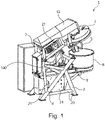
- the in the figures 1 and 2 shown kneading machine 1 is designed for processing a food dough, in particular a batter.
- the kneading machine 1 has a kneading machine frame 2 , the head part 3 of which can be pivoted about a pivot axis 100 between a lower operating position and an upper cleaning position in relation to a lower part 4 .
- the head part 3 carries the kneading tool 5, shown here are two counter-rotating helical kneaders, and the drive required for rotating the kneading tool 5, as well as a cover 7, which is provided to cover the kneading tub 8, which is open at the top.
- the kneading tub 8 and an electric motor 9 are arranged in the lower part 4 of the kneading machine 1 .
- the electric motor 9 rotates the kneading tub 8 about an axis of rotation (not shown) relative to the kneading machine frame 2.
- a swivel drive which is designed as a linear drive and has an electric motor.
- the swivel drive is supported on the lower part 4 in a rotary joint. By moving the linear drive, the distance from the head part 3 to the bottom part 4 is increased or decreased, which results in a pivoting of the head part 3 relative to the spatially fixed bottom part 4 about the pivot axis 100 .
- the kneading machine 1 has a housing 12 formed from stainless steel sheets.
- the housing 12 only covers the drive of the kneading tool.
- the kneading machine frame 2 is mostly exposed and is not surrounded by the housing 12 .
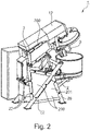
- cover 200 On the kneading machine frame 2 is an in figure 2 shown additional cover 200, which serves as an outer panel attached.
- the cover 200 is attached to the kneading machine frame 2 in a quick detachable manner.
- the cover 200 is made of a food grade, waterproof Material, in particular made of plastic or fiber-reinforced plastic. However, stainless steel or a fabric tarpaulin can also be used.
- the cover 200 has a plurality of plates 201 which each cover an intermediate space 21 formed by the struts 20 of the kneading machine frame 2 towards the outside.
- the cover 200 preferably replaces the conventionally used housing, ie it closes the kneading machine 1 apart from the kneading tub 8 and the kneading tools 5 from the outside.
- the cover 200 has no inwardly protruding surfaces or troughs and the number of contiguous surfaces of the cover 200 is reduced to a minimum, so that the cover 200 is easy to clean and does not require specially trained personnel for cleaning. Cleaning is preferably done with brushes or with water jets ⁇ 10 bar.
- the quick-release connections 22 allow the cover 200 to be removed and attached easily and quickly without additional tools.
- the quick-release connections can be designed as zipper connections, clip connections, Velcro connections, or a combination thereof.
- the cover can also be connected to the kneading machine frame and/or the housing by detachable connections such as cords, buttons, hooks and eyes.
- the cover is made of a transparent material.
- the operator can thus check the condition of the kneading machine, in particular also dirt on the kneading machine under the cover, without removing the cover. If cleaning, repair or maintenance is required, the cover can be quickly and easily detached and removed from the kneading machine.
- the material of the cover is preferably chosen so light that the cover can be removed by one person alone.
- the cover can be designed in several parts, with the sections also preferably being connected to one another by means of quick-release connections.
- the cover has a resealable opening that allows one to reach or walk through the cover and thus access the kneading machine frame without having to remove the entire cover.
- the cover allows cleaning to be carried out as usual without any additional effort.
- the cleaning staff does not need extra training and can keep the usual cleaning procedure.
- the cover can also be manufactured cheaply and is preferably easy to attach and remove by one person without tools.
Landscapes
- Chemical & Material Sciences (AREA)
- Chemical Kinetics & Catalysis (AREA)
- Life Sciences & Earth Sciences (AREA)
- Engineering & Computer Science (AREA)
- Food Science & Technology (AREA)
- Food-Manufacturing Devices (AREA)
- Manufacturing And Processing Devices For Dough (AREA)
Description
- Die vorliegende Erfindung betrifft eine Knetmaschine für Nahrungsmittelteige mit den Merkmalen des Oberbegriffs des Anspruchs 1.
- Knetmaschinen für Teige, insbesondere Backteige, weisen einen Knetbottich unterschiedlicher Größe für Teigmassen von 100 bis 3000 Kg auf, in den jeweils ein motorisch antreibbares Knetwerkzeug zur Durchführung des Knetvorganges hineinragt.
- Herkömmlicherweise weist eine solche Knetmaschine ein Gehäuse aus Edelstahl auf. Aus hygienischen und sicherheitsrelevanten Gründen sind bis auf das Knetwerkzeug und den Knetbottich alle Komponenten der Knetmaschine durch das Gehäuse verdeckt. Das Gehäuse ist mehrteilig ausgebildet und mittels Schraubverbindungen an dem Knetmaschinengestell befestigt. Das Gehäuse kann beispielsweise zu Wartungs- oder Reparaturzwecken von Fachpersonal demontiert werden. Das Gehäuse ist so ausgestaltet, dass es einfach von außen zu reinigen ist. Die Reinigung der Knetmaschine erfolgt mit Strahlwasser < 10bar. Dabei wird das Gehäuse von außen abgespritzt. Alternativ erfolgt eine trockene Reinigung durch Abbürsten.
- In naher Zukunft werden Knetmaschinen vorzugsweise mit einem sogenannten offenen Konzept auf den Markt gebracht, wie dies laut EHEDG Richtlinie vorgesehen ist. In einem offenen Konzept sind nur noch sicherheitsrelevante Komponenten der Knetmaschine, wie beispielswiese die hydraulischen und/oder elektrischen Antriebe, mit einem Gehäuse verkleidet. Das Knetmaschinengestell an sich ist dabei offengelegt und offen zugänglich. Ziel ist es, für eine optimale Hygiene alle Verunreinigungen sichtbar zu machen und nicht einsehbare Hohlräume zu vermeiden. Bei Knetmaschinengestellen mit verschwenkbarem Kopfteil muss daher zusätzlich eine Sicherheitsvorrichtung vorgesehen werden, die als Einklemmschutz für einen Bediener der Knetmaschine fungiert, denn das Gehäuse deckt nicht mehr die gesamte Knetmaschine ab und der Bediener kann in das Gestell greifen. Die Knetmaschine ist daher alleine aus Sicherheitsgründen bereits anders ausgestaltet als eine herkömmliche Knetmaschine. Auch an die Reinigung werden mit dem offenen Konzept andere Anforderungen gestellt. Denn eine Vielzahl an Oberflächen der Knetmaschine, die in unterschiedlichsten Winkeln zueinander liegen müssen nun gereinigt werden. Das führt dazu, dass die Reinigung deutlich umfangreicher und zeitaufwendiger wird. Die Broschüre "Brochure Spiral MD-W line" veröffentlicht unter https://www.eschermixers.com/images/EscherMixers_MD-MDW-line.pdf , gefunden am 2019-11-22 offenbart eine solche offene Knetmaschine mit rotierendem Bottich und rotierenden Knetwerkzeugen mit einem offenen Gestell gemäß dem Oberbegriff des Anspruch 1.
- Es ist daher Aufgabe der vorliegenden Erfindung eine Knetmaschine anzugeben, die ein offenes Konzept aufweist und trotzdem einfach zu reinigen ist.
- Diese Aufgabe wird von einer Knetmaschine für Teige mit den Merkmalen des Anspruchs 1 gelöst.
- Demnach ist eine Knetmaschine für Nahrungsmittelteige aufweisend ein Knetmaschinengestell mit einem Unterteil und ein an dem Unterteil befestigtes Kopfteil vorgesehen, wobei an dem Unterteil ein Knetbottich anordbar ist und ein Antrieb zur Drehung des Knetbottichs befestigt ist, und wobei an dem Kopfteil ein Knetwerkzeug und ein das Knetwerkzeug antreibender Antrieb gehalten ist, und wobei ausschließlich sicherheitsrelevante Komponenten der Knetmaschine von einem Gehäuse umgeben sind und ein Großteil des Knetmaschinengestells frei liegt, wobei das freiliegende Knetmaschinengestell Streben aufweist, zwischen den jeweils Freiräume gebildet sind, wobei die Knetmaschine eine abnehmbare Abdeckung aufweist, die zumindest einen Großteil der durch das freiliegende Knetmaschinengestell gebildeten Freiräume nach außen hin abdeckt, wobei die Abdeckung mittels schnell und ohne Werkzeug lösbaren Verbindungen an dem Knetmaschinengestell und/oder dem Gehäuse befestigt ist.
- Die schnell und ohne Werkzeug abnehmbare Abdeckung erlaubt es, dass die Reinigung der Teigknetmaschine, wie zuvor, auch bei einem offenen Konzept erfolgen kann.
- Vorzugsweise ist die Abdeckung aus einem lebensmittelechten, wasserundurchlässigen Material, insbesondere Kunststoff hergestellt.
- Es kann vorgesehen sein, dass die Abdeckung eine wiederverschließbare Öffnung aufweist.
- Bevorzugt ist die Abdeckung derart gestaltet, dass die Außenseite der Abdeckung mit einer Bürste von außen her einfach zu reinigen ist.
- Die schnell lösbaren Verbindungen sind vorzugsweise mittels Reißverschlussverbindung, Klips-Verbindungen, Klettband-Verbindungen, Schnappverschlüssen und/oder sonstige Schnellverschlüssen gebildet.
- Die Abdeckung kann sowohl einteilig als auch mehrteilig ausgebildet sein.
- Für den Fall, dass die Abdeckung mehrteilig ist, decken die einzelnen Teile der Abdeckung jeweils einen Freiraum zwischen den Streben des Knetmaschinengestells ab.
- Es ist vorteilhaft, wenn die Abdeckung zumindest einen Großteil der durch das freiliegende Knetmaschinengestell gebildeten Freiräume nach außen hin abdeckt, so dass nahezu kein Wasser und Staub beim Reinigen der Knetmaschine in einen vom Knetmaschinengestell umgebenen Innenraum dringt.
- Vorzugsweise umfassen die sicherheitsrelevanten Komponenten den Antrieb des Knetwerkzeugs.
- Das Gehäuse ist bevorzugt aus Stahl, Kunststoff oder GFK gebildet. Die Freiräume können am Kopfteil und/oder am Unterteil ausgebildet sein.
- Eine bevorzugte Ausführungsform der Erfindung wird nachfolgend anhand der Zeichnungen näher erläutert. Gleichartige oder gleichwirkende Bauteile werden in den Figuren mit denselben Bezugszeichen bezeichnet. Es zeigen:
- Figur 1:
- eine räumliche Darstellung einer Knetmaschine mit offenem Konzept, sowie
- Figur 2:
- eine räumliche Darstellung der Knetmaschine aus
Figur 1 mit einer zusätzlichen schnell lösbaren Abdeckung - Die in den
Figuren 1 und2 dargestellte Knetmaschine 1 ist zur Verarbeitung eines Nahrungsmittelteigs, insbesondere eines Backteigs ausgebildet. Die Knetmaschine 1 weist ein Knetmaschinengestell 2 auf, dessen Kopfteil 3 um eine Schwenkachse 100 zwischen einer unteren Betriebsstellung und einer oberen Reinigungsstellung gegenüber einem Unterteil 4 verschwenkbar ist. Das Kopfteil 3 trägt das Knetwerkzeug 5, hier dargestellt sind zwei entgegengesetzt drehende Wendelkneter, und den für eine Rotation des Knetwerkzeugs 5 benötigten Antrieb, sowie einen Deckel 7, der zum Abdecken des nach oben hin offenen Knetbottichs 8 vorgesehen ist. Im Unterteil 4 der Knetmaschine 1 sind der Knetbottich 8 und ein Elektromotor 9 angeordnet. Der Elektromotor 9 dreht den Knetbottich 8 um eine nicht dargestellte Rotationsachse gegenüber dem Knetmaschinengestell 2. Im Kopfteil 3 ist weiterhin ein Schwenkantrieb platziert, der als Linearantrieb ausgebildet ist und einen Elektromotor aufweist. Der Schwenkantrieb stützt sich an dem Unterteil 4 in einem Drehgelenk ab. Durch Verfahren des Linearantriebs wird der Abstand vom Kopfteil 3 zu dem Unterteil 4 vergrößert bzw. verkleinert, das in ein Verschwenken des Kopfteils 3 gegenüber dem raumfesten Unterteil 4 um die Schwenkachse 100 resultiert. - Die Knetmaschine 1 weist ein aus Edelstahlblechen gebildetes Gehäuse 12 auf. Das Gehäuse 12 deckt nur den Antrieb des Knetwerkzeugs ab. Das Knetmaschinengestell 2 liegt größtenteils frei und ist von dem Gehäuse 12 nicht umgeben.
- An dem Knetmaschinengestell 2 ist eine in
Figur 2 dargestellte zusätzliche Abdeckung 200, die als Außenverkleidung dient, befestigt. Die Abdeckung 200 ist schnell lösbar an dem Knetmaschinengestell 2 befestigt. Die Abdeckung 200 ist aus einem lebensmittelechten, wasserundurchlässigen Material, insbesondere Kunststoff oder faserverstärkter Kunststoff gefertigt. Es kann aber auch Edelstahl oder eine Gewebeplane verwendet werden. In der dargestellten Ausführungsform weist die Abdeckung 200 mehrere Platten 201 auf, die jeweils einen durch die Streben 20 des Knetmaschinengestells 2 gebildeten Zwischenraum 21 nach außen hin abdecken. Bevorzugt ersetzt die Abdeckung 200 das herkömmlich verwendete Gehäuse, d. h. sie verschließt die Knetmaschine 1 bis auf den Knetbottich 8 und die Knetwerkzeuge 5 nach außen hin ab. Die Abdeckung 200 weist keine nach innen ragenden Flächen oder Mulden auf und die Anzahl der aneinandergrenzenden Oberflächen der Abdeckung 200 ist auf ein Minimum reduziert, so dass die Abdeckung 200 einfach zu reinigen ist und kein besonders geschultes Personal für die Reinigung benötigt wird. Die Reinigung erfolgt bevorzugt mit Bürsten oder mit Strahlwasser <10bar. Die schnell lösbaren Verbindungen 22 erlauben es die Abdeckung 200 ohne zusätzliches Werkzeug einfach und schnell abzunehmen und anzubringen. Die schnell lösbaren Verbindungen können als Reißverschlussverbindungen, Klips-Verbindungen, Klettband-Verbindungen oder einer Kombination davon ausgebildet sein. - Es können auch andere schnell lösbare Formschlussverbindung verwendet werden, wie beispielswiese Schnappverschlüsse oder sonstige Schnellverschlüsse wie beispielsweise Bajonettverschlüsse oder dergleichen.
- Die Abdeckung kann auch durch lösbare Verbindungen wie Schnüre, Knöpfe, Haken und Ösen, mit dem Knetmaschinengestell und/oder dem Gehäuse verbunden sein.
- Es ist vorteilhafterweise vorgesehen, dass die Abdeckung aus einem transparenten Material gefertigt ist. Der Bediener kann somit ohne Entfernen der Abdeckung den Zustand der Knetmaschine, insbesondere auch ein Verdrecken der Knetmaschine unter der Abdeckung, kontrollieren. Bei Reinigungs-, Reparatur- oder Wartungsbedarf kann die Abdeckung schnell und einfach von der Knetmaschine gelöst und abgenommen werden. Das Material der Abdeckung ist dabei bevorzugt so leicht gewählt, dass die Abdeckung durch eine Person alleine entfernt werden kann.
- Die Abdeckung kann mehrteilig ausgebildet sein, wobei die Teilstücke untereinander ebenfalls bevorzugt mittels schnell lösbaren Verbindungen verbunden sind.
- Es kann auch vorgesehen sein, dass die Abdeckung eine widerverschließbare Öffnung aufweist, die es erlaubt durch die Abdeckung zu greifen oder zu gehen und somit das Knetmaschinengestell zugänglich macht, ohne das die gesamte Abdeckung entfernt werden muss.
- Die Abdeckung erlaubt es, dass trotz des offenen Konzepts der Knetmaschine die Reinigung wie gewohnt ohne Mehraufwand erfolgen kann. Das Reinigungspersonal muss nicht extra geschult werden und kann das übliche Reinigungsverfahren beibehalten. Die Abdeckung kann zudem günstig hergestellt werden und ist bevorzugt einfach durch eine Person ohne Werkzeug anzubringen und abzunehmen.
Claims (11)
- Knetmaschine (1) für Nahrungsmittelteige aufweisend ein Knetmaschinengestell (2) mit einem Unterteil (4) und ein an dem Unterteil befestigtes Kopfteil, wobei an dem Unterteil (4) ein Knetbottich (8) anordbar ist und ein Antrieb zur Drehung des Knetbottichs befestigt ist, und wobei an dem Kopfteil (3) ein Knetwerkzeug (5) und ein das Knetwerkzeug (5) antreibender Antrieb gehalten ist, und wobei ausschließlich sicherheitsrelevante Komponenten der Knetmaschine (1) von einem Gehäuse (12) umgeben sind und ein Großteil des Knetmaschinengestells (2) frei liegt, wobei das freiliegende Knetmaschinengestell Streben (20) aufweist, zwischen den jeweils Freiräume (21) gebildet sind, dadurch gekennzeichnet, dass die Knetmaschine eine abnehmbare Abdeckung (200) aufweist, die zumindest einen Großteil der durch das freiliegende Knetmaschinengestell gebildeten Freiräume nach außen hin abdeckt, wobei die Abdeckung (200) mittels schnell und ohne Werkzeug lösbaren Verbindungen (22) an dem Knetmaschinengestell und/oder dem Gehäuse befestigt ist.
- Knetmaschine nach Anspruch 1, dadurch gekennzeichnet, dass die Abdeckung (200) aus einem lebensmittelechten, wasserundurchlässigen Material hergestellt ist.
- Knetmaschine nach Anspruch 1 oder 2, dadurch gekennzeichnet, dass die Abdeckung (200) aus einem Kunststoff hergestellt ist.
- Knetmaschine nach einem der vorhergehenden Ansprüche, dadurch gekennzeichnet, dass die Abdeckung (200) eine wiederverschließbare Öffnung aufweist.
- Knetmaschine nach einem der vorhergehenden Ansprüche, dadurch gekennzeichnet, dass die Abdeckung (200) derart gestaltet ist, dass die Außenseite der Abdeckung (200) mit einer Bürste von außen her einfach zu reinigen ist.
- Knetmaschine nach einem der vorhergehenden Ansprüche, dadurch gekennzeichnet, dass die schnell lösbaren Verbindungen (22) mittels Reißverschlussverbindung, Klips-Verbindungen, Klettband-Verbindungen, Schnappverschlüssen und/oder sonstige Schnellverschlüssen gebildet sind.
- Knetmaschine nach einem der vorhergehenden Ansprüche, dadurch gekennzeichnet, dass die Abdeckung (200) einteilig ausgebildet ist.
- Knetmaschine nach einem der vorhergehenden Ansprüche 1 bis 7, dadurch gekennzeichnet, dass die Abdeckung (200) mehrteilig ausgebildet ist.
- Knetmaschine nach Anspruch 8, dadurch gekennzeichnet, dass die einzelnen Teile (201) der Abdeckung (200) jeweils einen Freiraum (21) zwischen den Streben (20) abdecken.
- Knetmaschine nach einem der vorhergehenden Ansprüche 1 bis 9, dadurch gekennzeichnet, dass die Abdeckung (200) zumindest einen Großteil der durch das freiliegende Knetmaschinengestell gebildeten Freiräume (21) nach außen hin abdeckt, so dass nahezu kein Wasser und Staub beim Reinigen der Knetmaschine (1) in einen vom Knetmaschinengestell (2) umgebenen Innenraum dringt.
- Knetmaschine nach einem der vorhergehenden Ansprüche, dadurch gekennzeichnet, dass die sicherheitsrelevanten Komponenten den Antrieb des Knetwerkzeugs (5) umfassen.
Priority Applications (5)
| Application Number | Priority Date | Filing Date | Title |
|---|---|---|---|
| PL19205818.8T PL3815533T3 (pl) | 2019-10-29 | 2019-10-29 | Ugniatarka do ciast spożywczych z pokrywą z szybkozłączem |
| EP19205818.8A EP3815533B1 (de) | 2019-10-29 | 2019-10-29 | Knetmaschine für nahrungsmittelteige mit einer abdeckung mit schnellverschluss |
| CN202080080139.5A CN114727606B (zh) | 2019-10-29 | 2020-09-02 | 具有快锁盖的用于食品面团的揉捏机 |
| PCT/EP2020/074445 WO2021083569A1 (de) | 2019-10-29 | 2020-09-02 | Knetmaschine für nahrungsmittelteige mit einer abdeckung mit schnellverschluss |
| US17/772,664 US12490745B2 (en) | 2019-10-29 | 2020-09-02 | Kneading machine for food doughs, having a cover having a quick closure |
Applications Claiming Priority (1)
| Application Number | Priority Date | Filing Date | Title |
|---|---|---|---|
| EP19205818.8A EP3815533B1 (de) | 2019-10-29 | 2019-10-29 | Knetmaschine für nahrungsmittelteige mit einer abdeckung mit schnellverschluss |
Publications (2)
| Publication Number | Publication Date |
|---|---|
| EP3815533A1 EP3815533A1 (de) | 2021-05-05 |
| EP3815533B1 true EP3815533B1 (de) | 2022-06-15 |
Family
ID=68387213
Family Applications (1)
| Application Number | Title | Priority Date | Filing Date |
|---|---|---|---|
| EP19205818.8A Active EP3815533B1 (de) | 2019-10-29 | 2019-10-29 | Knetmaschine für nahrungsmittelteige mit einer abdeckung mit schnellverschluss |
Country Status (5)
| Country | Link |
|---|---|
| US (1) | US12490745B2 (de) |
| EP (1) | EP3815533B1 (de) |
| CN (1) | CN114727606B (de) |
| PL (1) | PL3815533T3 (de) |
| WO (1) | WO2021083569A1 (de) |
Families Citing this family (3)
| Publication number | Priority date | Publication date | Assignee | Title |
|---|---|---|---|---|
| PL3815533T3 (pl) * | 2019-10-29 | 2022-11-28 | DIOSNA Dierks & Söhne GmbH | Ugniatarka do ciast spożywczych z pokrywą z szybkozłączem |
| PL3970498T3 (pl) * | 2020-09-21 | 2024-06-17 | DIOSNA Dierks & Söhne GmbH | Ugniatarka do ciast spożywczych z uszczelnieniem narzędzi ugniatających |
| EP4678004A1 (de) * | 2024-07-09 | 2026-01-14 | DIOSNA Dierks & Söhne GmbH | Knetmaschine mit eigensicherem verschwenken eines tropfschutzes |
Family Cites Families (21)
| Publication number | Priority date | Publication date | Assignee | Title |
|---|---|---|---|---|
| FR382120A (fr) * | 1907-09-21 | 1908-01-30 | Georges Levasseur | Pétrin mécanique |
| US3561643A (en) * | 1968-09-16 | 1971-02-09 | Ramsey Eng Co | Feeder for particulate material, having means responsive to the rate of flow |
| JPS5171884U (de) * | 1974-11-30 | 1976-06-07 | ||
| JPS53149096U (de) * | 1977-04-28 | 1978-11-24 | ||
| US4162857A (en) * | 1977-12-12 | 1979-07-31 | Specialized Products, Inc. | Apparatus for stirring grain |
| RU2101956C1 (ru) * | 1992-07-30 | 1998-01-20 | Петров Борис Александрович | Тестомесильная машина |
| US5368196A (en) * | 1993-03-25 | 1994-11-29 | Fluid Management Limited Partnership | Apparatus for metering and dispensing flowable materials to form a blended composition |
| IT1294110B1 (it) * | 1997-01-02 | 1999-03-22 | Antonio Cimenti | Porzionatrice per paste alimentari |
| KR200352998Y1 (ko) * | 2004-03-30 | 2004-06-09 | 우행기 | 곡분 반죽기 |
| US8579161B2 (en) * | 2009-05-15 | 2013-11-12 | William R. Steeb | Low profile batter dispenser |
| CN203952262U (zh) * | 2014-08-06 | 2014-11-26 | 丁炯华 | 和面机 |
| US11097946B1 (en) * | 2015-02-27 | 2021-08-24 | Daniel W. Lynn | System for creating an oxidation reduction potential (ORP) in water with pipe assembly for in-line mixing |
| US9635865B1 (en) * | 2015-05-18 | 2017-05-02 | Norman Schmidt | Dough feeder |
| WO2018067898A1 (en) * | 2016-10-06 | 2018-04-12 | Burford Corporation | Fine particulate dispenser with quick access panel |
| CN108041109A (zh) * | 2018-02-02 | 2018-05-18 | 海宁市麦米米食品有限公司 | 一种易清洗糕点和面机 |
| EP3772281B1 (de) * | 2019-08-07 | 2022-04-06 | DIOSNA Dierks & Söhne GmbH | Knetmaschine für teige mit einklemmschutz und verfahren zum einschwenken eines knetwerkzeugs |
| PL3815533T3 (pl) * | 2019-10-29 | 2022-11-28 | DIOSNA Dierks & Söhne GmbH | Ugniatarka do ciast spożywczych z pokrywą z szybkozłączem |
| PL3970498T3 (pl) * | 2020-09-21 | 2024-06-17 | DIOSNA Dierks & Söhne GmbH | Ugniatarka do ciast spożywczych z uszczelnieniem narzędzi ugniatających |
| CN112690298B (zh) * | 2020-12-31 | 2022-03-29 | 杭州心芽信息科技有限公司 | 一种面制品自动和面机及糕点加工工艺 |
| EP4115738B1 (de) * | 2021-07-08 | 2024-10-23 | DIOSNA Dierks & Söhne GmbH | Knetmaschine mit zentraler ölbesprühung, verwendung der knetmaschine und verfahren zum besprühen eines transportbehälters |
| EP4331365B1 (de) * | 2022-09-01 | 2025-02-19 | DIOSNA Dierks & Söhne GmbH | Knetmaschine für nahrungsmittelteige mit not-halt-einrichtung und verfahren zur steuerung einer knetmaschine für nahrungsmittelteige |
-
2019
- 2019-10-29 PL PL19205818.8T patent/PL3815533T3/pl unknown
- 2019-10-29 EP EP19205818.8A patent/EP3815533B1/de active Active
-
2020
- 2020-09-02 WO PCT/EP2020/074445 patent/WO2021083569A1/de not_active Ceased
- 2020-09-02 US US17/772,664 patent/US12490745B2/en active Active
- 2020-09-02 CN CN202080080139.5A patent/CN114727606B/zh active Active
Also Published As
| Publication number | Publication date |
|---|---|
| EP3815533A1 (de) | 2021-05-05 |
| CN114727606B (zh) | 2023-05-05 |
| US20220400689A1 (en) | 2022-12-22 |
| CN114727606A (zh) | 2022-07-08 |
| WO2021083569A1 (de) | 2021-05-06 |
| PL3815533T3 (pl) | 2022-11-28 |
| US12490745B2 (en) | 2025-12-09 |
Similar Documents
| Publication | Publication Date | Title |
|---|---|---|
| EP3815533B1 (de) | Knetmaschine für nahrungsmittelteige mit einer abdeckung mit schnellverschluss | |
| DE4038634C2 (de) | ||
| DE3136773C2 (de) | Filter- und Heizvorrichtung zur Filtration aufgeschlämmter Flüssigkeiten und zur Trocknung der Kuchen | |
| DE3413531C2 (de) | ||
| DE60103253T2 (de) | Reinigen von oberflächen | |
| AT13531U1 (de) | Poolreinigungsroboter | |
| DE2917960A1 (de) | Vorrichtung zum waschen und trocknen von lebensmitteln, insbesondere gemuese und obst | |
| DE2640670A1 (de) | Elektrisch betreibbarer entsafter fuer den haushaltsgebrauch | |
| DE9301281U1 (de) | Vorrichtung zum Reinigen von Arbeitsgeräten von Malerbetrieben | |
| WO2009129834A1 (de) | Elektrische bürstenvorrichtung zur körperpflege und -massage | |
| DE60113750T2 (de) | Sanitäreinheit mit Toilettenreinigung | |
| DE102013212136A1 (de) | System und Verfahren zum Reinigen von rotierbaren Elementen eines Etikettieraggregats | |
| EP2704580B1 (de) | Verfahren zur reinigung von backplatten einer backautomatenanlage und reinigungsvorrichtung | |
| DE3439146A1 (de) | Verkuerzungs- und reinigungsgeraet fuer porree | |
| DE20009519U1 (de) | Mobile Textilbelags-Reinigungsmaschine | |
| DE60214500T2 (de) | Vorrichtung zum Waschen von Gemüse und Mollusken | |
| DE69816343T2 (de) | Automatischer waschtunnel zum reinigen und desinfizieren der innen- und aussenseite von abfallbehältern | |
| DE10049325A1 (de) | Vorrichtung zum Reinigen von Sonnenschutzanlagen | |
| DE19802852C2 (de) | Speiseeisherstellungsmaschine | |
| DE1981317U (de) | Loesungsmittelfilter, insbesondere fuer trockenreinigungsanlagen. | |
| DE202004017530U1 (de) | Einspannvorrichtung einer Blasformmaschine | |
| WO2011067126A1 (de) | Reinigungsvorrichtung zum reinigen eines hufs eines huftiers | |
| WO1987006921A1 (fr) | Dispositif pour nettoyer des boites | |
| DE632070C (de) | Ununterbrochen arbeitendes Druckfilter fuer Fluessigkeiten | |
| DE3425799A1 (de) | Kettenangetriebener kaemmkopf fuer bueschel von textilfasern |
Legal Events
| Date | Code | Title | Description |
|---|---|---|---|
| PUAI | Public reference made under article 153(3) epc to a published international application that has entered the european phase |
Free format text: ORIGINAL CODE: 0009012 |
|
| STAA | Information on the status of an ep patent application or granted ep patent |
Free format text: STATUS: THE APPLICATION HAS BEEN PUBLISHED |
|
| AK | Designated contracting states |
Kind code of ref document: A1 Designated state(s): AL AT BE BG CH CY CZ DE DK EE ES FI FR GB GR HR HU IE IS IT LI LT LU LV MC MK MT NL NO PL PT RO RS SE SI SK SM TR |
|
| STAA | Information on the status of an ep patent application or granted ep patent |
Free format text: STATUS: REQUEST FOR EXAMINATION WAS MADE |
|
| 17P | Request for examination filed |
Effective date: 20210907 |
|
| RBV | Designated contracting states (corrected) |
Designated state(s): AL AT BE BG CH CY CZ DE DK EE ES FI FR GB GR HR HU IE IS IT LI LT LU LV MC MK MT NL NO PL PT RO RS SE SI SK SM TR |
|
| REG | Reference to a national code |
Ref country code: DE Ref legal event code: R079 Ref document number: 502019004637 Country of ref document: DE Free format text: PREVIOUS MAIN CLASS: A21C0001020000 Ipc: B01F0027723000 |
|
| GRAP | Despatch of communication of intention to grant a patent |
Free format text: ORIGINAL CODE: EPIDOSNIGR1 |
|
| STAA | Information on the status of an ep patent application or granted ep patent |
Free format text: STATUS: GRANT OF PATENT IS INTENDED |
|
| RIC1 | Information provided on ipc code assigned before grant |
Ipc: A21C 1/14 20060101ALI20220114BHEP Ipc: A21C 1/02 20060101ALI20220114BHEP Ipc: B01F 35/00 20220101ALI20220114BHEP Ipc: B01F 35/10 20220101ALI20220114BHEP Ipc: B01F 29/85 20220101ALI20220114BHEP Ipc: B01F 27/807 20220101ALI20220114BHEP Ipc: B01F 27/723 20220101AFI20220114BHEP |
|
| INTG | Intention to grant announced |
Effective date: 20220203 |
|
| GRAS | Grant fee paid |
Free format text: ORIGINAL CODE: EPIDOSNIGR3 |
|
| GRAA | (expected) grant |
Free format text: ORIGINAL CODE: 0009210 |
|
| STAA | Information on the status of an ep patent application or granted ep patent |
Free format text: STATUS: THE PATENT HAS BEEN GRANTED |
|
| AK | Designated contracting states |
Kind code of ref document: B1 Designated state(s): AL AT BE BG CH CY CZ DE DK EE ES FI FR GB GR HR HU IE IS IT LI LT LU LV MC MK MT NL NO PL PT RO RS SE SI SK SM TR |
|
| REG | Reference to a national code |
Ref country code: CH Ref legal event code: EP Ref country code: GB Ref legal event code: FG4D Free format text: NOT ENGLISH |
|
| REG | Reference to a national code |
Ref country code: IE Ref legal event code: FG4D Free format text: LANGUAGE OF EP DOCUMENT: GERMAN |
|
| REG | Reference to a national code |
Ref country code: DE Ref legal event code: R096 Ref document number: 502019004637 Country of ref document: DE |
|
| REG | Reference to a national code |
Ref country code: AT Ref legal event code: REF Ref document number: 1498021 Country of ref document: AT Kind code of ref document: T Effective date: 20220715 |
|
| REG | Reference to a national code |
Ref country code: LT Ref legal event code: MG9D |
|
| REG | Reference to a national code |
Ref country code: NL Ref legal event code: MP Effective date: 20220615 |
|
| PG25 | Lapsed in a contracting state [announced via postgrant information from national office to epo] |
Ref country code: SE Free format text: LAPSE BECAUSE OF FAILURE TO SUBMIT A TRANSLATION OF THE DESCRIPTION OR TO PAY THE FEE WITHIN THE PRESCRIBED TIME-LIMIT Effective date: 20220615 Ref country code: NO Free format text: LAPSE BECAUSE OF FAILURE TO SUBMIT A TRANSLATION OF THE DESCRIPTION OR TO PAY THE FEE WITHIN THE PRESCRIBED TIME-LIMIT Effective date: 20220915 Ref country code: LT Free format text: LAPSE BECAUSE OF FAILURE TO SUBMIT A TRANSLATION OF THE DESCRIPTION OR TO PAY THE FEE WITHIN THE PRESCRIBED TIME-LIMIT Effective date: 20220615 Ref country code: HR Free format text: LAPSE BECAUSE OF FAILURE TO SUBMIT A TRANSLATION OF THE DESCRIPTION OR TO PAY THE FEE WITHIN THE PRESCRIBED TIME-LIMIT Effective date: 20220615 Ref country code: GR Free format text: LAPSE BECAUSE OF FAILURE TO SUBMIT A TRANSLATION OF THE DESCRIPTION OR TO PAY THE FEE WITHIN THE PRESCRIBED TIME-LIMIT Effective date: 20220916 Ref country code: FI Free format text: LAPSE BECAUSE OF FAILURE TO SUBMIT A TRANSLATION OF THE DESCRIPTION OR TO PAY THE FEE WITHIN THE PRESCRIBED TIME-LIMIT Effective date: 20220615 Ref country code: BG Free format text: LAPSE BECAUSE OF FAILURE TO SUBMIT A TRANSLATION OF THE DESCRIPTION OR TO PAY THE FEE WITHIN THE PRESCRIBED TIME-LIMIT Effective date: 20220915 |
|
| PG25 | Lapsed in a contracting state [announced via postgrant information from national office to epo] |
Ref country code: RS Free format text: LAPSE BECAUSE OF FAILURE TO SUBMIT A TRANSLATION OF THE DESCRIPTION OR TO PAY THE FEE WITHIN THE PRESCRIBED TIME-LIMIT Effective date: 20220615 Ref country code: LV Free format text: LAPSE BECAUSE OF FAILURE TO SUBMIT A TRANSLATION OF THE DESCRIPTION OR TO PAY THE FEE WITHIN THE PRESCRIBED TIME-LIMIT Effective date: 20220615 |
|
| PG25 | Lapsed in a contracting state [announced via postgrant information from national office to epo] |
Ref country code: NL Free format text: LAPSE BECAUSE OF FAILURE TO SUBMIT A TRANSLATION OF THE DESCRIPTION OR TO PAY THE FEE WITHIN THE PRESCRIBED TIME-LIMIT Effective date: 20220615 |
|
| PG25 | Lapsed in a contracting state [announced via postgrant information from national office to epo] |
Ref country code: SM Free format text: LAPSE BECAUSE OF FAILURE TO SUBMIT A TRANSLATION OF THE DESCRIPTION OR TO PAY THE FEE WITHIN THE PRESCRIBED TIME-LIMIT Effective date: 20220615 Ref country code: SK Free format text: LAPSE BECAUSE OF FAILURE TO SUBMIT A TRANSLATION OF THE DESCRIPTION OR TO PAY THE FEE WITHIN THE PRESCRIBED TIME-LIMIT Effective date: 20220615 Ref country code: RO Free format text: LAPSE BECAUSE OF FAILURE TO SUBMIT A TRANSLATION OF THE DESCRIPTION OR TO PAY THE FEE WITHIN THE PRESCRIBED TIME-LIMIT Effective date: 20220615 Ref country code: PT Free format text: LAPSE BECAUSE OF FAILURE TO SUBMIT A TRANSLATION OF THE DESCRIPTION OR TO PAY THE FEE WITHIN THE PRESCRIBED TIME-LIMIT Effective date: 20221017 Ref country code: ES Free format text: LAPSE BECAUSE OF FAILURE TO SUBMIT A TRANSLATION OF THE DESCRIPTION OR TO PAY THE FEE WITHIN THE PRESCRIBED TIME-LIMIT Effective date: 20220615 Ref country code: EE Free format text: LAPSE BECAUSE OF FAILURE TO SUBMIT A TRANSLATION OF THE DESCRIPTION OR TO PAY THE FEE WITHIN THE PRESCRIBED TIME-LIMIT Effective date: 20220615 |
|
| PG25 | Lapsed in a contracting state [announced via postgrant information from national office to epo] |
Ref country code: PL Free format text: LAPSE BECAUSE OF FAILURE TO SUBMIT A TRANSLATION OF THE DESCRIPTION OR TO PAY THE FEE WITHIN THE PRESCRIBED TIME-LIMIT Effective date: 20220615 Ref country code: IS Free format text: LAPSE BECAUSE OF FAILURE TO SUBMIT A TRANSLATION OF THE DESCRIPTION OR TO PAY THE FEE WITHIN THE PRESCRIBED TIME-LIMIT Effective date: 20221015 |
|
| REG | Reference to a national code |
Ref country code: DE Ref legal event code: R097 Ref document number: 502019004637 Country of ref document: DE |
|
| PG25 | Lapsed in a contracting state [announced via postgrant information from national office to epo] |
Ref country code: AL Free format text: LAPSE BECAUSE OF FAILURE TO SUBMIT A TRANSLATION OF THE DESCRIPTION OR TO PAY THE FEE WITHIN THE PRESCRIBED TIME-LIMIT Effective date: 20220615 |
|
| PLBE | No opposition filed within time limit |
Free format text: ORIGINAL CODE: 0009261 |
|
| STAA | Information on the status of an ep patent application or granted ep patent |
Free format text: STATUS: NO OPPOSITION FILED WITHIN TIME LIMIT |
|
| PG25 | Lapsed in a contracting state [announced via postgrant information from national office to epo] |
Ref country code: DK Free format text: LAPSE BECAUSE OF FAILURE TO SUBMIT A TRANSLATION OF THE DESCRIPTION OR TO PAY THE FEE WITHIN THE PRESCRIBED TIME-LIMIT Effective date: 20220615 |
|
| 26N | No opposition filed |
Effective date: 20230316 |
|
| PG25 | Lapsed in a contracting state [announced via postgrant information from national office to epo] |
Ref country code: SI Free format text: LAPSE BECAUSE OF FAILURE TO SUBMIT A TRANSLATION OF THE DESCRIPTION OR TO PAY THE FEE WITHIN THE PRESCRIBED TIME-LIMIT Effective date: 20220615 Ref country code: MC Free format text: LAPSE BECAUSE OF FAILURE TO SUBMIT A TRANSLATION OF THE DESCRIPTION OR TO PAY THE FEE WITHIN THE PRESCRIBED TIME-LIMIT Effective date: 20220615 |
|
| REG | Reference to a national code |
Ref country code: CH Ref legal event code: PL |
|
| REG | Reference to a national code |
Ref country code: BE Ref legal event code: MM Effective date: 20221031 |
|
| P01 | Opt-out of the competence of the unified patent court (upc) registered |
Effective date: 20230523 |
|
| PG25 | Lapsed in a contracting state [announced via postgrant information from national office to epo] |
Ref country code: LU Free format text: LAPSE BECAUSE OF NON-PAYMENT OF DUE FEES Effective date: 20221029 |
|
| PG25 | Lapsed in a contracting state [announced via postgrant information from national office to epo] |
Ref country code: LI Free format text: LAPSE BECAUSE OF NON-PAYMENT OF DUE FEES Effective date: 20221031 Ref country code: CH Free format text: LAPSE BECAUSE OF NON-PAYMENT OF DUE FEES Effective date: 20221031 |
|
| PG25 | Lapsed in a contracting state [announced via postgrant information from national office to epo] |
Ref country code: BE Free format text: LAPSE BECAUSE OF NON-PAYMENT OF DUE FEES Effective date: 20221031 |
|
| PG25 | Lapsed in a contracting state [announced via postgrant information from national office to epo] |
Ref country code: IE Free format text: LAPSE BECAUSE OF NON-PAYMENT OF DUE FEES Effective date: 20221029 |
|
| PGFP | Annual fee paid to national office [announced via postgrant information from national office to epo] |
Ref country code: FR Payment date: 20231019 Year of fee payment: 5 |
|
| PG25 | Lapsed in a contracting state [announced via postgrant information from national office to epo] |
Ref country code: CY Free format text: LAPSE BECAUSE OF FAILURE TO SUBMIT A TRANSLATION OF THE DESCRIPTION OR TO PAY THE FEE WITHIN THE PRESCRIBED TIME-LIMIT Effective date: 20220615 |
|
| PG25 | Lapsed in a contracting state [announced via postgrant information from national office to epo] |
Ref country code: MK Free format text: LAPSE BECAUSE OF FAILURE TO SUBMIT A TRANSLATION OF THE DESCRIPTION OR TO PAY THE FEE WITHIN THE PRESCRIBED TIME-LIMIT Effective date: 20220615 Ref country code: HU Free format text: LAPSE BECAUSE OF FAILURE TO SUBMIT A TRANSLATION OF THE DESCRIPTION OR TO PAY THE FEE WITHIN THE PRESCRIBED TIME-LIMIT; INVALID AB INITIO Effective date: 20191029 |
|
| GBPC | Gb: european patent ceased through non-payment of renewal fee |
Effective date: 20231029 |
|
| PG25 | Lapsed in a contracting state [announced via postgrant information from national office to epo] |
Ref country code: TR Free format text: LAPSE BECAUSE OF FAILURE TO SUBMIT A TRANSLATION OF THE DESCRIPTION OR TO PAY THE FEE WITHIN THE PRESCRIBED TIME-LIMIT Effective date: 20220615 |
|
| PG25 | Lapsed in a contracting state [announced via postgrant information from national office to epo] |
Ref country code: GB Free format text: LAPSE BECAUSE OF NON-PAYMENT OF DUE FEES Effective date: 20231029 |
|
| PG25 | Lapsed in a contracting state [announced via postgrant information from national office to epo] |
Ref country code: GB Free format text: LAPSE BECAUSE OF NON-PAYMENT OF DUE FEES Effective date: 20231029 |
|
| PG25 | Lapsed in a contracting state [announced via postgrant information from national office to epo] |
Ref country code: MT Free format text: LAPSE BECAUSE OF FAILURE TO SUBMIT A TRANSLATION OF THE DESCRIPTION OR TO PAY THE FEE WITHIN THE PRESCRIBED TIME-LIMIT Effective date: 20220615 |
|
| PG25 | Lapsed in a contracting state [announced via postgrant information from national office to epo] |
Ref country code: BG Free format text: LAPSE BECAUSE OF FAILURE TO SUBMIT A TRANSLATION OF THE DESCRIPTION OR TO PAY THE FEE WITHIN THE PRESCRIBED TIME-LIMIT Effective date: 20220615 |
|
| REG | Reference to a national code |
Ref country code: DE Ref legal event code: R082 Ref document number: 502019004637 Country of ref document: DE Representative=s name: EGE LEE & ROIDER PATENTANWAELTE PARTGMBB, DE |
|
| PG25 | Lapsed in a contracting state [announced via postgrant information from national office to epo] |
Ref country code: BG Free format text: LAPSE BECAUSE OF FAILURE TO SUBMIT A TRANSLATION OF THE DESCRIPTION OR TO PAY THE FEE WITHIN THE PRESCRIBED TIME-LIMIT Effective date: 20220615 |
|
| PGFP | Annual fee paid to national office [announced via postgrant information from national office to epo] |
Ref country code: PL Payment date: 20241004 Year of fee payment: 6 |
|
| PGFP | Annual fee paid to national office [announced via postgrant information from national office to epo] |
Ref country code: CZ Payment date: 20241025 Year of fee payment: 6 |
|
| PGFP | Annual fee paid to national office [announced via postgrant information from national office to epo] |
Ref country code: IT Payment date: 20241031 Year of fee payment: 6 |
|
| PG25 | Lapsed in a contracting state [announced via postgrant information from national office to epo] |
Ref country code: FR Free format text: LAPSE BECAUSE OF NON-PAYMENT OF DUE FEES Effective date: 20241031 |
|
| REG | Reference to a national code |
Ref country code: AT Ref legal event code: MM01 Ref document number: 1498021 Country of ref document: AT Kind code of ref document: T Effective date: 20241029 |
|
| PGFP | Annual fee paid to national office [announced via postgrant information from national office to epo] |
Ref country code: DE Payment date: 20250923 Year of fee payment: 7 |
|
| PG25 | Lapsed in a contracting state [announced via postgrant information from national office to epo] |
Ref country code: AT Free format text: LAPSE BECAUSE OF NON-PAYMENT OF DUE FEES Effective date: 20241029 |
|
| PGFP | Annual fee paid to national office [announced via postgrant information from national office to epo] |
Ref country code: AT Payment date: 20260410 Year of fee payment: 5 |