EP3815565B1 - Anneau de type joint - Google Patents
Anneau de type joint Download PDFInfo
- Publication number
- EP3815565B1 EP3815565B1 EP18924797.6A EP18924797A EP3815565B1 EP 3815565 B1 EP3815565 B1 EP 3815565B1 EP 18924797 A EP18924797 A EP 18924797A EP 3815565 B1 EP3815565 B1 EP 3815565B1
- Authority
- EP
- European Patent Office
- Prior art keywords
- module
- joint
- ring setting
- magnet
- fixed
- Prior art date
- Legal status (The legal status is an assumption and is not a legal conclusion. Google has not performed a legal analysis and makes no representation as to the accuracy of the status listed.)
- Active
Links
Images




Classifications
-
- A—HUMAN NECESSITIES
- A44—HABERDASHERY; JEWELLERY
- A44C—PERSONAL ADORNMENTS, e.g. JEWELLERY; COINS
- A44C5/00—Bracelets; Wrist-watch straps; Fastenings for bracelets or wrist-watch straps
- A44C5/18—Fasteners for straps, chains or the like
- A44C5/20—Fasteners for straps, chains or the like for open straps, chains or the like
- A44C5/2057—Fasteners locked by sliding or rotating of the male element of the fastener; Turn-button fasteners
- A44C5/2061—Fasteners locked by sliding or rotating of the male element of the fastener; Turn-button fasteners combined with spring means
-
- A—HUMAN NECESSITIES
- A44—HABERDASHERY; JEWELLERY
- A44C—PERSONAL ADORNMENTS, e.g. JEWELLERY; COINS
- A44C9/00—Finger-rings
- A44C9/0038—Finger-rings openable or able to be broken for safety reasons
- A44C9/0046—Finger-rings openable or able to be broken for safety reasons comprising a hinge
-
- A—HUMAN NECESSITIES
- A44—HABERDASHERY; JEWELLERY
- A44C—PERSONAL ADORNMENTS, e.g. JEWELLERY; COINS
- A44C9/00—Finger-rings
- A44C9/02—Finger-rings adjustable
-
- A—HUMAN NECESSITIES
- A44—HABERDASHERY; JEWELLERY
- A44C—PERSONAL ADORNMENTS, e.g. JEWELLERY; COINS
- A44C5/00—Bracelets; Wrist-watch straps; Fastenings for bracelets or wrist-watch straps
- A44C5/02—Link constructions
-
- A—HUMAN NECESSITIES
- A44—HABERDASHERY; JEWELLERY
- A44C—PERSONAL ADORNMENTS, e.g. JEWELLERY; COINS
- A44C5/00—Bracelets; Wrist-watch straps; Fastenings for bracelets or wrist-watch straps
- A44C5/02—Link constructions
- A44C5/10—Link constructions not extensible
- A44C5/107—Link constructions not extensible with links made of more than two elements including connecting elements
-
- A—HUMAN NECESSITIES
- A44—HABERDASHERY; JEWELLERY
- A44D—INDEXING SCHEME RELATING TO BUTTONS, PINS, BUCKLES OR SLIDE FASTENERS, AND TO JEWELLERY, BRACELETS OR OTHER PERSONAL ADORNMENTS
- A44D2203/00—Fastening by use of magnets
Definitions
- the innovative product relates to the technical field of ornamental finger rings and watchbands, and particularly relates to a spliceable, assemblable, bendable and adjustable joint finger ring.
- the document JPS5348157Y2 discloses a joint finger ring having an adjustable size and can be bent, disassembled and assembled.
- the purpose of the innovative product is to overcome the defects and disadvantages of the prior art and provide a joint finger ring.
- the whole structure of the finger ring is composed of three parts: one is a ring setting, wherein the ring setting is a main integral part of this type of finger rings, and various jewelries, inlays and appearances of the ring setting can be changed through the modular disassembling and assembling of components of the ring setting.
- the second is ring plane inlays, which play a role in adding a finishing touch to make the appearance beautiful.
- the ring plane inlays are embedded into inlay wrapping materials to form an integral module to achieve an modular disassembling and assembling effect, so that the inlays, the appearances of the inlays or the overall appearance of the finger ring can be appropriately adjusted.
- the third is connection components which movably connect two ends of the ring setting. Through finely-adjustable connection module, the finger ring can be comfortably worn onto the finger.
- the joint finger ring is composed of a ring setting, inlays and connection components, wherein the inlays are arranged on the ring setting through inlay wrapping materials, and the left end and the right end of the ring setting are movably connected through the connection components.
- various functions such as splicing, bending, disassembling, assembling and adjusting can be realized.
- the ring setting is similar to a watchband, and capable of being bent, disassembled and assembled and can adjust the appearance of the ring setting.
- the ring setting is composed of ring setting components, C-shaped pins and C-shaped pipes or fixed caps and fixed pins.
- the structure of the ring setting can be disassembled and assembled in a modularization manner, so that the appearance adjustability of the ring setting can be realized.
- the ring setting is made of precious metals such as gold, platinum, silver or ordinary metals or wooden materials, ceramic materials, clay materials, jadeite, Hetian jade materials, Shoushan stone materials, marble materials or purple sands.
- the inlay is a part to beautify the appearance of the ring setting. Compared with the previous process of directly embedding the inlays into the ring setting, this type of finger rings can be freely disassembled and assembled by inserting the inlays into the inlay wrapping materials in advance, thereby achieving the appropriate adjustment of the appearance of the ring setting.
- connection components is composed of a module A and a module B to form functions of movable connection and fine adjustment, which incorporates the design concepts of ergonomics, overall aesthetics, ultra-thin standards, convenient use, and feasible craftsmanship.
- a joint finger ring (as shown in Fig. 1 ) is composed of a ring setting 1, inlays 2 and connection components 3, wherein the inlays 2 are embedded into inlay wrapping materials to form an integral module to be arranged into the ring setting 1.
- the left end and the right end of the ring setting 1 are movably connected through the connection components 3.
- the ring setting 1 is similar to a watchband and can be bent, disassembled and assembled.
- the ring setting is composed of ring setting components 21, C-shaped pins 22 and C-shaped pipes 23 or fixed pins 24 and fixed caps 25.
- the fixed pin 24 can be correspondingly connected with the fixed cap 25.
- the fixed cap 25 can be correspondingly connected with the fixed pin 24.
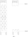
- the ring setting components 21 are modular components that can be disassembled and assembled into the appearance of the ring setting 1 (as shown in Fig. 7-Fig. 9 ).
- the inlays are embedded into the inlay wrapping materials to form the integral module to be arranged in the ring setting 1 (as shown in Fig. 8-Fig. 10 ).
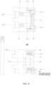
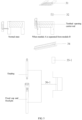
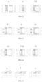
- connection component 3 is composed of a module A and a module B to form the movable connection (as shown in Fig. 12 and Fig. 17-Fig. 19).
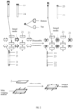
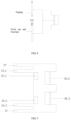
- the module A includes a lock switch button 31, a return spring 32 or a return magnet 32-1 and a return magnet 32-2, module A joint bayonets 33-1, a fixed bulge or notch 34, a module A ring setting joint 35-1 or 35-2 and 35-3 (as shown in Fig. 13 ).
- the return spring 32 or the return magnet 32-1 and the return magnet 32-2 are located right below the tail of the module A lock switch button 31 (as shown in Fig. 13 ).
- the module A joint bayonets 33-1 are located at two sides of the lock switch button 31.
- the module A joint bayonet 33-1 is composed of a toothed opening, a toothed opening spring or a toothed opening return magnet 1, a toothed opening carrier rod and a movable knuckle (as shown in Fig. 13 ).
- the toothed opening is located in the toothed opening carrier rod and is a row of triangular movable exposed bayonets.
- the toothed opening carrier rod is connected with the lock switch button 31 through the movable knuckle.
- the movable knuckle is perpendicular to a position between the toothed opening carrier rod and the lock switch button 31 (as shown in Fig. 14-Fig. 15 ).
- the fixed bulge or notch 34 is located on the left end and the right end of the module A and is used for the up-down fixation of the module A and the module B at a connection state correspondingly together with the fixed notch or bulge 37 in the module B.
- the module A passes through the ring setting joint 35-1 to be connected with one end of the ring setting through an earplug or the module A is connected with one end of the ring setting through the connection of the ring setting joint 35-2 and the ring setting joint 35-32 and the fixed pin 34 and the fixed cap 35 (as shown in Fig. 13 ).
- the finger ring can be worn on the finger; and when the module A and the module B are separated by the user, the lock switch button 31 is pressed down; after the toothed opening carrier rod is pulled towards the inner side through the movable knuckle, the toothed opening is separated from a slot in the module B joint bayonets 33-2, thereby separating the module A and the module B (as shown in Fig. 17).
- the components in the module A and the module B are on fixed positions.
- the first joint bayonet 33-1 on the front end of the module A is connected with a connection position of the second joint bayonet 33-2 on the front end of the module B.
- the exposed toothed opening of the module A may be continuously pushed by the module A joint bayonets 33-2 to have a telescopic motion so as to be fixed in the longitudinal direction.
- the fixed bulge or notch 34 in the module A is correspondingly connected with the fixed notch or bulge 37 in the module B so as to fix the module A in the vertical direction and to adjust the feeling to the best state.
- the toothed opening is under the action of the toothed opening spring or the toothed opening return magnet 1.
- the toothed opening spring or the toothed opening return magnet 1 Through the toothed opening spring or the toothed opening return magnet 1, the triangular slot on the connection position of the joint bayonets 33-2 in the module B can be correspondingly connected with the toothed opening along with the connection action.
- the module A and the module B are correspondingly connected in the vertical and longitudinal directions, and each component in the module A is returned.
- the lock switch button 31 is pushed backwards first, and at this moment, the exposed toothed opening may be retracted inwards, so that the module A and the module B have no fixed connection in the longitudinal direction.
- each component in the module A is returned.
- this innovative design solves the problem that in the wearing process of the traditional finger rings, the size of the finger ring of the favorite style is appropriately increased at the beginning of selection or customization so as to fit the finger. As a result, it is impossible to achieve the best feeling when people wear the finger ring; and moreover, due to a lot of reasons, the finger ring may not be taken off, which is more obvious especially for the characteristics of male finger bones. Meanwhile, when the consumer needs the product of the same style with different appearances, only the corresponding accessories need to be added, so that the trouble for purchasing the whole product with the original structure can be avoided. Based on the market demand, this design incorporates the design concepts of ergonomics, overall aesthetics, ultra-thin standards, convenient use and feasible craftsmanship. The innovative design is made on the basis of the traditional concept of the existing finger ring, thereby providing technical and material basis to fill a gap in the market.
Landscapes
- Adornments (AREA)
Claims (4)
- anneau de doigt de joint, comportant un réglage de lanneau (1), des incrustations (2) et des composants de raccordement ts (3), dans lequel les incrustations (2) sont disposées dans le réglage de lanneau (1) par des matériaux denveloppement dincrustation, et lextrémité gauche et droite de larrangement de lanneau (1) sont reliées de manière mobile par les connectés sur les composants (3);Le réglage de lanneau (1) est similaire à un brandeau de montre, peut être plié, démonté et emballé, et est composé de composants de réglage de lanneau (21), en forme de 2pc 2 Broches (22) et tuyaux en forme de c (23) ou capuchons fixes 2 P (24) 2 et fixe 2 pins (25); 2 pis,Les composants de réglage (21) sont fabriqués en module intégral et en métaux précieux comprenant du platine, lor et largent ou en module intégral et en métal ordinaire,Où le composant de raccordement (3) est composé dun module a et dun module b à un raccordement mobile forméLe module b comprend un second aimant magnétique à pierre (35-2), une seconde baïonette de joint (33-2), un second joint de réglage en anneau (36-2) et une encoche fixe (37);Le module a comprend un bouton de serrure (31), un ressort de retour (32), des premières baïonettes de joint (33-1), une boulée fixe (34), une première pierre ou aimant magnétique (35-1) et un premier joint de joint de joint (36-1), et le premier joint de joint de joint (36-1) est relié au module a et à une extrémité de la joint de joint à travers un blocage ou les capuchons fixes et les broches fixes; Ou le module a comprend un bouton de verrouillage (31), un aimant de retour (32 -1), un aimant de retour (32-2), une première baïonette de joint s (33-1), une boulée fixe (34), une première pierre ou aimant magnétique (35-1) et une première joint de réglage de lanneau (36-1), la première joint de réglage de lanneau (36-1) est composée du blocage ou des broches fixes et des capuchons fixes pour raccorder la mousse à une extrémité de la joint de réglage de lanneau; Et...Le deuxième joint de réglage de lanneau (36-2) est situé sur le côté gauche et droit de lextrémité inférieure du module b et relié au module b et à lautre extrémité du réglage de lanneau par le blocage doreille, ou les bouchons fixes et les broches fixes, où le deuxième joint de réglage de lanneau (36-2) est composé du blocage doreille, ou les bouchons fixes et les broches fixes.
- Lanneau de doigt de joint selon la revendication 1, dans lequel les incrustations (2) sont enroulées dans des matériaux denveloppe dincrustation pour former un module intégral à disposer dans le réglage de ring (1).
- Lanneau de doigt conjoint selon la revendication 1, dans lequel les composants de réglage de lanneau (21) sont des modules démontés et assemblés dans lapparence de lanneau de réglage (1), et
Composé de métaux précieux, de métal ordine ou dun module intégral formé par les incrustations et les matériaux denveloppe dincrustations. - Lanneau de doigt de joint selon la revendication 1, dans lequel lorsque le module a comprend le bouton de verrouillage (31), le ressort de roulette (32), les premières baïonettes de joint (33-1), le boulage fixe (34), la première pierre ou aimant magnétique (35-1) et le premier joint de joint de joint (36-1);Le bouton de commutation de verrouillage (31) utilisé pour séparer mobilement le module a et le module b est situé au milieu de lensemble du module a;Le ressort de retour (32) est situé juste sous la queue du bouton de commutation de verrouillage du module (31);La première baïonette de joint (33-1) est localisée sur deux côtés du bouton de serrure (31), et chaque première joint La baïonette (33-1) est composée dune ouverture dentée, dun ressort douverture dentée, dune tige douverture dentée et dune jointe mobile,Dans quelle mesureLouverture dentée est située dans la tige porteuse douverture dentée et constitue une rangée de baïonettes exposées triangulaires mobiles; Le ressort douverture denté est situé dans louverture dentée et relié au ressort douverture denté et à la tige porteuse douverture dentée, colonne creuse rugueuse en forme dabarrel, sur la fronte;La tige de support douverture dentée est connectée au bouton de commutation de verrouillage (31) par une jointe mobile, et la jointe mobile est perpendiculaire à une position entre la tige de support douverture dentée et le bouton de commutation de verrouillage (31);Le bouleversement fixe (34) est situé sur la gauche e nd et sur lextrémité droite du module a et correspond à la bouleversement fixe (37) dans le moduleb; Et...Lorsque le module a comprend le bouton de verrouillage (31), laimant de retour (32-1), laimant de retour (32-2), les premières baïonettes de joint (33-1), le bouleversement fixe (34), le premier aimant magnétique de pierre de sapin (35-1) et le premier joint de ringring (36-1);Le bouton de verrouillage (31) utilisé pour séparer en mouvement le module a et le module b est situé au milieu de lensemble du module a;Laimant de retour (32-1) est situé à lintérieur du module un bouton de commutation de verrouillage (31) et joue un rôle de repousser laimant de retour (32-2) en raison de polarités similaires;Laimant de retour (32-2) est situé au milieu du module a et joue un rôle de repousse à laimant de retour (32-1) en raison de polarités similaires;Les premières baïonnettes de joint (33-1) sont situées sur deux côtés du bouton de verrouillage (31), et chacune des premières baïonnettes de joint (33-1) est composée dune ouverture dentée, dun aimant douverture dentée (1), dun aimant denté (2), dune tige de support de jointe mobile (38) et dune jointe mobile,Où louverture dentée est située à une extrémité de louverture dentée, cest une rangée de baïonettes exposées triangulaires mobiles, et est fixément reliée à louverture m a par une colonne creuse cylindrique à lextrémité avant et fixément reliée à une extrémité de louverture dentée par une colonne creuse cylindrique dans louverture dentée;La jointe mobile située entre louverture dentée et la tige porteuse mobile (38); Une extrémité est reliée à louverture dentée et une extrémité est reliée à la tige porteuse de la jointe mobile (38), où laimant de retour douverture dentée (1) est situé sur la jointe mobile et joue un rôle de repousse de laimant denté (2) en raison de polarités similaires;La tige porteuse de jointe mobile (38) est située entre la jointe mobile et le bouton de verrouillage (31), où laimant denté (2) est situé dans la tige porteuse de jointe mobile (38) et joue un rôle de repousser laimant de retour douverture denté (1) en raison de polarités similaires;Le bouleversement fixe (34) est situé sur la gauche e nd et sur lextrémité droite du module a et correspond à la bouleversement fixe (37) dans le moduleb; Et...Le deuxième aimant magnétique de pierre (35-2) est corrélé au premier aimant magnétique de pierre (35-1) dans le module;Lencoche fixe (37) est située sur lextrémité gauche et droite du module b et correspond à la boulée fixe (34) dans les modules a;La deuxième baïonette de joint (33-2) est située sur deux cuboïdes aux côtés supérieurs du module b, le cuboïde comprend à lintérieur une rangée de triangulaires exposés; Et les enceintes triangulaires sont correspondant à louverture dentée dans la première baïonette de joint (33-1) du module a.
Applications Claiming Priority (1)
| Application Number | Priority Date | Filing Date | Title |
|---|---|---|---|
| PCT/CN2018/093810 WO2020000420A1 (fr) | 2018-06-29 | 2018-06-29 | Anneau de type joint |
Publications (4)
| Publication Number | Publication Date |
|---|---|
| EP3815565A1 EP3815565A1 (fr) | 2021-05-05 |
| EP3815565A4 EP3815565A4 (fr) | 2022-03-23 |
| EP3815565C0 EP3815565C0 (fr) | 2025-02-19 |
| EP3815565B1 true EP3815565B1 (fr) | 2025-02-19 |
Family
ID=68984601
Family Applications (1)
| Application Number | Title | Priority Date | Filing Date |
|---|---|---|---|
| EP18924797.6A Active EP3815565B1 (fr) | 2018-06-29 | 2018-06-29 | Anneau de type joint |
Country Status (3)
| Country | Link |
|---|---|
| US (1) | US11369171B2 (fr) |
| EP (1) | EP3815565B1 (fr) |
| WO (1) | WO2020000420A1 (fr) |
Families Citing this family (3)
| Publication number | Priority date | Publication date | Assignee | Title |
|---|---|---|---|---|
| CN112137255A (zh) * | 2020-10-09 | 2020-12-29 | 盈利时表业(东莞)有限公司 | 一种易拆装型结构及其带有该易拆装型结构的表带 |
| EP4298948B1 (fr) * | 2022-06-30 | 2025-02-26 | Comadur S.A. | Bracelet avec maillons en materiau dur |
| CN223251576U (zh) * | 2024-09-24 | 2025-08-22 | 永康市一顺工具有限公司 | 一种电动工具的工具头锁扣结构 |
Family Cites Families (12)
| Publication number | Priority date | Publication date | Assignee | Title |
|---|---|---|---|---|
| FR568919A (fr) * | 1923-07-21 | 1924-04-03 | Bague sertie tout autour pouvant s'agrandir à volonté | |
| JPS5348157Y2 (fr) * | 1976-06-22 | 1978-11-17 | ||
| US4158951A (en) * | 1977-05-11 | 1979-06-26 | Cedar Samuel N | Ring or bracelet having pivoted locking clasp |
| CH697560B1 (fr) * | 2003-08-27 | 2008-11-28 | Pierre Salanitro | Pièce de bijouterie à maillons articulés, notamment un bracelet, un collier ou un bracelet-montre. |
| CN101642314A (zh) * | 2009-08-27 | 2010-02-10 | 苏州工业园区博友钛钢科技有限公司 | 一种手链 |
| GB2475065B (en) | 2009-11-04 | 2012-04-04 | Vector Int Ltd | Seal ring and joint |
| CN201822079U (zh) * | 2010-07-20 | 2011-05-11 | 吴瑞熙 | 一种球形自锁磁吸扣 |
| US9809047B2 (en) | 2013-02-18 | 2017-11-07 | U.S. Ring Binder, L.P. | Ring lock guard for a ring binder |
| CN104490023B (zh) * | 2014-12-18 | 2017-05-03 | 赵威 | 互换式扭钉首饰锁扣 |
| CN205410010U (zh) * | 2016-02-17 | 2016-08-03 | 李原林 | 一种可自由调节手寸的戒指 |
| CN205432434U (zh) * | 2016-03-22 | 2016-08-10 | 高孝品 | 表带快拆结构 |
| CN107041609B (zh) * | 2017-05-03 | 2019-01-18 | 兴固五金(深圳)有限公司 | 一种表带的简易拆装结构及手表 |
-
2018
- 2018-06-29 EP EP18924797.6A patent/EP3815565B1/fr active Active
- 2018-06-29 WO PCT/CN2018/093810 patent/WO2020000420A1/fr not_active Ceased
-
2020
- 2020-10-01 US US17/060,200 patent/US11369171B2/en active Active
Also Published As
| Publication number | Publication date |
|---|---|
| EP3815565A1 (fr) | 2021-05-05 |
| EP3815565C0 (fr) | 2025-02-19 |
| EP3815565A4 (fr) | 2022-03-23 |
| US20210015221A1 (en) | 2021-01-21 |
| US11369171B2 (en) | 2022-06-28 |
| WO2020000420A1 (fr) | 2020-01-02 |
Similar Documents
| Publication | Publication Date | Title |
|---|---|---|
| US11369171B2 (en) | Joint finger ring | |
| US20190281932A1 (en) | Necklace | |
| KR102069057B1 (ko) | 제작단가가 절감되면서 볼륨감이 있는 펜던트 제조방법 | |
| KR200485628Y1 (ko) | 조립형 목걸이 세트 | |
| KR200471068Y1 (ko) | 의류에 사용하는 장식물 | |
| KR200469408Y1 (ko) | 조립식 액세서리용 팬던트 | |
| WO2012066584A1 (fr) | Anneau doté d'éléments de verrouillage interchangeables | |
| CN208387996U (zh) | 一种接口件 | |
| KR102537047B1 (ko) | 반지 및 목걸이로 가변되는 장신구 | |
| CN222367244U (zh) | 一种多层组合、拆卸并可调节尺寸的首饰结构 | |
| CN211048576U (zh) | 一种新型的具有两种佩戴方式的珠宝结构 | |
| JP2025066859A (ja) | バンド | |
| KR101150835B1 (ko) | 코디 귀걸이 | |
| CN223452891U (zh) | 一种组合式手镯 | |
| CN212852735U (zh) | 一种定位装置 | |
| CN207626700U (zh) | 一种接口式戒指 | |
| KR200397718Y1 (ko) | 조립식 반지 | |
| KR200252416Y1 (ko) | 악세사리용 장신구 | |
| KR200380796Y1 (ko) | 형태 변형이 가능한 목걸이용 펜던트 | |
| KR200463726Y1 (ko) | 장식부가 가변이 되는 펜던트 | |
| US20050172669A1 (en) | Ornamental item with variable configuration, and method for its manufacture | |
| JP3194596U (ja) | スライドによるコンビネーション装身具 | |
| KR200360664Y1 (ko) | 다기능 장신구 | |
| KR200339649Y1 (ko) | 장신구용 펜던트 | |
| CN206333475U (zh) | 一种无焊点拼接首饰 |
Legal Events
| Date | Code | Title | Description |
|---|---|---|---|
| STAA | Information on the status of an ep patent application or granted ep patent |
Free format text: STATUS: THE INTERNATIONAL PUBLICATION HAS BEEN MADE |
|
| PUAI | Public reference made under article 153(3) epc to a published international application that has entered the european phase |
Free format text: ORIGINAL CODE: 0009012 |
|
| STAA | Information on the status of an ep patent application or granted ep patent |
Free format text: STATUS: REQUEST FOR EXAMINATION WAS MADE |
|
| 17P | Request for examination filed |
Effective date: 20210129 |
|
| AK | Designated contracting states |
Kind code of ref document: A1 Designated state(s): AL AT BE BG CH CY CZ DE DK EE ES FI FR GB GR HR HU IE IS IT LI LT LU LV MC MK MT NL NO PL PT RO RS SE SI SK SM TR |
|
| DAV | Request for validation of the european patent (deleted) | ||
| DAX | Request for extension of the european patent (deleted) | ||
| A4 | Supplementary search report drawn up and despatched |
Effective date: 20220217 |
|
| RIC1 | Information provided on ipc code assigned before grant |
Ipc: A44C 5/10 20060101ALN20220211BHEP Ipc: A44C 5/20 20060101ALI20220211BHEP Ipc: A44C 11/02 20060101ALI20220211BHEP Ipc: A44C 5/14 20060101ALI20220211BHEP Ipc: A44C 9/02 20060101AFI20220211BHEP |
|
| GRAP | Despatch of communication of intention to grant a patent |
Free format text: ORIGINAL CODE: EPIDOSNIGR1 |
|
| RIC1 | Information provided on ipc code assigned before grant |
Ipc: A44C 5/10 20060101ALN20241008BHEP Ipc: A44C 5/20 20060101ALI20241008BHEP Ipc: A44C 11/02 20060101ALI20241008BHEP Ipc: A44C 5/14 20060101ALI20241008BHEP Ipc: A44C 9/02 20060101AFI20241008BHEP |
|
| STAA | Information on the status of an ep patent application or granted ep patent |
Free format text: STATUS: GRANT OF PATENT IS INTENDED |
|
| RIC1 | Information provided on ipc code assigned before grant |
Ipc: A44C 5/10 20060101ALN20241024BHEP Ipc: A44C 5/20 20060101ALI20241024BHEP Ipc: A44C 11/02 20060101ALI20241024BHEP Ipc: A44C 5/14 20060101ALI20241024BHEP Ipc: A44C 9/02 20060101AFI20241024BHEP |
|
| INTG | Intention to grant announced |
Effective date: 20241114 |
|
| GRAS | Grant fee paid |
Free format text: ORIGINAL CODE: EPIDOSNIGR3 |
|
| GRAA | (expected) grant |
Free format text: ORIGINAL CODE: 0009210 |
|
| STAA | Information on the status of an ep patent application or granted ep patent |
Free format text: STATUS: THE PATENT HAS BEEN GRANTED |
|
| AK | Designated contracting states |
Kind code of ref document: B1 Designated state(s): AL AT BE BG CH CY CZ DE DK EE ES FI FR GB GR HR HU IE IS IT LI LT LU LV MC MK MT NL NO PL PT RO RS SE SI SK SM TR |
|
| REG | Reference to a national code |
Ref country code: GB Ref legal event code: FG4D |
|
| REG | Reference to a national code |
Ref country code: CH Ref legal event code: EP |
|
| REG | Reference to a national code |
Ref country code: IE Ref legal event code: FG4D |
|
| REG | Reference to a national code |
Ref country code: DE Ref legal event code: R096 Ref document number: 602018079466 Country of ref document: DE |
|
| U01 | Request for unitary effect filed |
Effective date: 20250306 |
|
| U07 | Unitary effect registered |
Designated state(s): AT BE BG DE DK EE FI FR IT LT LU LV MT NL PT RO SE SI Effective date: 20250314 |
|
| U20 | Renewal fee for the european patent with unitary effect paid |
Year of fee payment: 8 Effective date: 20250528 |
|
| PG25 | Lapsed in a contracting state [announced via postgrant information from national office to epo] |
Ref country code: RS Free format text: LAPSE BECAUSE OF FAILURE TO SUBMIT A TRANSLATION OF THE DESCRIPTION OR TO PAY THE FEE WITHIN THE PRESCRIBED TIME-LIMIT Effective date: 20250519 |
|
| PG25 | Lapsed in a contracting state [announced via postgrant information from national office to epo] |
Ref country code: PL Free format text: LAPSE BECAUSE OF FAILURE TO SUBMIT A TRANSLATION OF THE DESCRIPTION OR TO PAY THE FEE WITHIN THE PRESCRIBED TIME-LIMIT Effective date: 20250219 |
|
| PG25 | Lapsed in a contracting state [announced via postgrant information from national office to epo] |
Ref country code: ES Free format text: LAPSE BECAUSE OF FAILURE TO SUBMIT A TRANSLATION OF THE DESCRIPTION OR TO PAY THE FEE WITHIN THE PRESCRIBED TIME-LIMIT Effective date: 20250219 |
|
| PGFP | Annual fee paid to national office [announced via postgrant information from national office to epo] |
Ref country code: GB Payment date: 20250625 Year of fee payment: 8 |
|
| PG25 | Lapsed in a contracting state [announced via postgrant information from national office to epo] |
Ref country code: IS Free format text: LAPSE BECAUSE OF FAILURE TO SUBMIT A TRANSLATION OF THE DESCRIPTION OR TO PAY THE FEE WITHIN THE PRESCRIBED TIME-LIMIT Effective date: 20250619 Ref country code: NO Free format text: LAPSE BECAUSE OF FAILURE TO SUBMIT A TRANSLATION OF THE DESCRIPTION OR TO PAY THE FEE WITHIN THE PRESCRIBED TIME-LIMIT Effective date: 20250519 |
|
| PG25 | Lapsed in a contracting state [announced via postgrant information from national office to epo] |
Ref country code: HR Free format text: LAPSE BECAUSE OF FAILURE TO SUBMIT A TRANSLATION OF THE DESCRIPTION OR TO PAY THE FEE WITHIN THE PRESCRIBED TIME-LIMIT Effective date: 20250219 |
|
| PG25 | Lapsed in a contracting state [announced via postgrant information from national office to epo] |
Ref country code: GR Free format text: LAPSE BECAUSE OF FAILURE TO SUBMIT A TRANSLATION OF THE DESCRIPTION OR TO PAY THE FEE WITHIN THE PRESCRIBED TIME-LIMIT Effective date: 20250520 |
|
| PG25 | Lapsed in a contracting state [announced via postgrant information from national office to epo] |
Ref country code: SM Free format text: LAPSE BECAUSE OF FAILURE TO SUBMIT A TRANSLATION OF THE DESCRIPTION OR TO PAY THE FEE WITHIN THE PRESCRIBED TIME-LIMIT Effective date: 20250219 |
|
| PGFP | Annual fee paid to national office [announced via postgrant information from national office to epo] |
Ref country code: CH Payment date: 20250701 Year of fee payment: 8 |
|
| PG25 | Lapsed in a contracting state [announced via postgrant information from national office to epo] |
Ref country code: CZ Free format text: LAPSE BECAUSE OF FAILURE TO SUBMIT A TRANSLATION OF THE DESCRIPTION OR TO PAY THE FEE WITHIN THE PRESCRIBED TIME-LIMIT Effective date: 20250219 |
|
| PG25 | Lapsed in a contracting state [announced via postgrant information from national office to epo] |
Ref country code: SK Free format text: LAPSE BECAUSE OF FAILURE TO SUBMIT A TRANSLATION OF THE DESCRIPTION OR TO PAY THE FEE WITHIN THE PRESCRIBED TIME-LIMIT Effective date: 20250219 |
|
| PLBE | No opposition filed within time limit |
Free format text: ORIGINAL CODE: 0009261 |
|
| STAA | Information on the status of an ep patent application or granted ep patent |
Free format text: STATUS: NO OPPOSITION FILED WITHIN TIME LIMIT |
|
| REG | Reference to a national code |
Ref country code: CH Ref legal event code: L10 Free format text: ST27 STATUS EVENT CODE: U-0-0-L10-L00 (AS PROVIDED BY THE NATIONAL OFFICE) Effective date: 20251231 |
|
| 26N | No opposition filed |
Effective date: 20251120 |
|
| PG25 | Lapsed in a contracting state [announced via postgrant information from national office to epo] |
Ref country code: MC Free format text: LAPSE BECAUSE OF FAILURE TO SUBMIT A TRANSLATION OF THE DESCRIPTION OR TO PAY THE FEE WITHIN THE PRESCRIBED TIME-LIMIT Effective date: 20250219 |
|
| PG25 | Lapsed in a contracting state [announced via postgrant information from national office to epo] |
Ref country code: IE Free format text: LAPSE BECAUSE OF NON-PAYMENT OF DUE FEES Effective date: 20250629 |