EP3815575B1 - Ensemble rail coulissant - Google Patents
Ensemble rail coulissant Download PDFInfo
- Publication number
- EP3815575B1 EP3815575B1 EP20167075.9A EP20167075A EP3815575B1 EP 3815575 B1 EP3815575 B1 EP 3815575B1 EP 20167075 A EP20167075 A EP 20167075A EP 3815575 B1 EP3815575 B1 EP 3815575B1
- Authority
- EP
- European Patent Office
- Prior art keywords
- rail
- working
- wall
- stop
- slide rail
- Prior art date
- Legal status (The legal status is an assumption and is not a legal conclusion. Google has not performed a legal analysis and makes no representation as to the accuracy of the status listed.)
- Active
Links
Images






Classifications
-
- A—HUMAN NECESSITIES
- A47—FURNITURE; DOMESTIC ARTICLES OR APPLIANCES; COFFEE MILLS; SPICE MILLS; SUCTION CLEANERS IN GENERAL
- A47B—TABLES; DESKS; OFFICE FURNITURE; CABINETS; DRAWERS; GENERAL DETAILS OF FURNITURE
- A47B88/00—Drawers for tables, cabinets or like furniture; Guides for drawers
- A47B88/40—Sliding drawers; Slides or guides therefor
- A47B88/473—Braking devices, e.g. linear or rotational dampers or friction brakes; Buffers; End stops
- A47B88/477—Buffers; End stops
-
- A—HUMAN NECESSITIES
- A47—FURNITURE; DOMESTIC ARTICLES OR APPLIANCES; COFFEE MILLS; SPICE MILLS; SUCTION CLEANERS IN GENERAL
- A47B—TABLES; DESKS; OFFICE FURNITURE; CABINETS; DRAWERS; GENERAL DETAILS OF FURNITURE
- A47B88/00—Drawers for tables, cabinets or like furniture; Guides for drawers
- A47B88/40—Sliding drawers; Slides or guides therefor
- A47B88/44—Sequencing or synchronisation of drawer slides or functional units
- A47B88/443—Successive movement of rails within drawer slides, i.e. at least one rail element is not moving during the movement of other elements
-
- A—HUMAN NECESSITIES
- A47—FURNITURE; DOMESTIC ARTICLES OR APPLIANCES; COFFEE MILLS; SPICE MILLS; SUCTION CLEANERS IN GENERAL
- A47B—TABLES; DESKS; OFFICE FURNITURE; CABINETS; DRAWERS; GENERAL DETAILS OF FURNITURE
- A47B88/00—Drawers for tables, cabinets or like furniture; Guides for drawers
- A47B88/40—Sliding drawers; Slides or guides therefor
- A47B88/49—Sliding drawers; Slides or guides therefor with double extensible guides or parts
-
- A—HUMAN NECESSITIES
- A47—FURNITURE; DOMESTIC ARTICLES OR APPLIANCES; COFFEE MILLS; SPICE MILLS; SUCTION CLEANERS IN GENERAL
- A47B—TABLES; DESKS; OFFICE FURNITURE; CABINETS; DRAWERS; GENERAL DETAILS OF FURNITURE
- A47B88/00—Drawers for tables, cabinets or like furniture; Guides for drawers
- A47B88/40—Sliding drawers; Slides or guides therefor
- A47B88/49—Sliding drawers; Slides or guides therefor with double extensible guides or parts
- A47B88/493—Sliding drawers; Slides or guides therefor with double extensible guides or parts with rollers, ball bearings, wheels, or the like
-
- A—HUMAN NECESSITIES
- A47—FURNITURE; DOMESTIC ARTICLES OR APPLIANCES; COFFEE MILLS; SPICE MILLS; SUCTION CLEANERS IN GENERAL
- A47B—TABLES; DESKS; OFFICE FURNITURE; CABINETS; DRAWERS; GENERAL DETAILS OF FURNITURE
- A47B88/00—Drawers for tables, cabinets or like furniture; Guides for drawers
- A47B88/50—Safety devices or the like for drawers
- A47B88/57—Safety devices or the like for drawers preventing complete withdrawal of the drawer
Definitions
- the present invention relates to a slide rail assembly and more particularly to a slide rail assembly that can be of different lengths to adapt to different environments.
- a slide rail assembly includes at least two slide rails that can be displaced with respect to each other to bring the slide rail assembly into an extended or retracted state.
- a drawer slide with locks includes a chassis member (i.e., the inner rail), an intermediate member (i.e., the intermediate rail), and a cabinet member (i.e., the outer rail).
- the intermediate member when at an extended position with respect to the cabinet member, is blocked between a forward stop and a rearward stop of the cabinet member via a rear lock and is thus kept at the extended position.
- the rear lock can be moved from between the forward stop and the rearward stop by retracting the chassis member with respect to the intermediate member.
- the rear lock includes a lock pin and a torsion spring.
- the lock pin is resiliently biased by the torsion spring and is configured to be blocked between the forward stop and the rearward stop of the cabinet member.
- the slide rail assembly disclosed in US Patent No. 7,980,641 B2 includes an outer slide rail, an intermediate slide rail, and an inner slide rail.
- the outer slide rail has a protrusion.
- the intermediate slide rail is provided with a latch member and a resilient member.
- the inner slide rail has a stop portion. When the inner slide rail is pulled in an opening direction with respect to the intermediate slide rail, the stop portion of the inner slide rail engages with the latch member of the intermediate slide rail such that the intermediate slide rail can be pulled with respect to the outer slide rail in the opening direction (see FIG. 5 of the '641 patent).
- the latch member of the intermediate slide rail engages with an inclined surface of the protrusion of the outer slide rail, resulting in a force that drives the latch member out of engagement with the stop portion of the inner slide rail (see FIG. 6 of the '641 patent).
- the resilient member of the intermediate slide rail is substantially R-shaped, is made of a metal wire, and biases the latch member resiliently in order to keep the latch member at a predetermined position.
- slide rail assemblies are disclosed, for example, in US 10 342 341 B2 , US 9 498 060 B1 , US 7 413 269 B2 , US 6 935 710 B2 and GB 2 417 191 B .
- the present invention provides a slide rail assembly that can be of different lengths to facilitate use in a narrow space.
- a slide rail assembly includes a first rail, a second rail, a first stop, and a working member.
- the second rail can be longitudinally displaced with respect to the first rail.
- the first stop is disposed on the first rail.
- the working member is movably mounted on the second rail. When the second rail reaches a predetermined position after being displaced with respect to the first rail from an extended position in a retracting direction, the first stop blocks the second rail through the working member to prevent the second rail from being displaced from the predetermined position in an opening direction.
- the slide rail assembly has a first length when the second rail is at the extended position.
- the slide rail assembly has a second length shorter than the first length when the second rail is at the predetermined position.
- the second rail includes a first wall, a second wall, and a longitudinal wall connected between the first wall and the second wall of the second rail, and
- the longitudinal wall of the second rail has a first position-limiting wall section, a second position-limiting wall section, and an extension hole defined between the first position-limiting wall section and the second position-limiting wall section, wherein the extension hole allows the working portion to extend therethrough.
- the working member is provided with a working portion.
- the first stop blocks the working member through the working portion to prevent the second rail from being displaced from the predetermined position in the opening direction.
- the working portion has a columnar configuration.
- the elastic structure applies the elastic force to the working member.
- the slide rail assembly further includes a second stop disposed on the first rail.
- the second stop blocks the working member through the working portion to prevent the second rail from being displaced from the predetermined position in the retracting direction.
- the slide rail assembly further includes a blocking structure disposed on the first rail and an engaging member movably mounted on the second rail.
- the blocking structure blocks the second rail through the engaging member to prevent the second rail from being displaced from the extended position in the retracting direction.
- the first stop blocks the second rail through the working member to prevent the second rail from being displaced from the predetermined position in the opening direction.
- the slide rail assembly further includes a pivotal connection member for pivotally connecting the engaging member to the longitudinal wall of the second rail in a height direction, wherein the height direction is substantially perpendicular to the transverse direction.
- the slide rail assembly further includes an elastic feature for applying an elastic force to the engaging member.
- the slide rail assembly further includes an operating member disposed on one of the first rail and the second rail, and the operating member is configured to be operated in order to drive the engaging member and thereby free the engaging member from blockage by the blocking structure.
- the slide rail assembly further includes a third rail that can be longitudinally displaced with respect to the second rail, and the second rail is movably mounted between the first rail and the third rail.
- the slide rail assembly 20 includes a first rail 22, a second rail 24, and a third rail 26.
- the first rail 22 includes a first wall 28a, a second wall 28b, and a longitudinal wall 30 connected between the first wall 28a and the second wall 28b of the first rail 22.
- the first wall 28a, the second wall 28b, and the longitudinal wall 30 of the first rail 22 jointly define a first channel for receiving the second rail 24.
- the slide rail assembly 20 further includes a first stop 32, a second stop 34, and a blocking structure 36, all disposed on the longitudinal wall 30 of the first rail 22.
- the first stop 32 and the second stop 34 define a receiving space X therebetween.
- the first stop 32 and the second stop 34 are symmetrically arranged and have substantially the same structural configuration. Take the first stop 32 for example.
- the first stop 32 has a first guiding portion G1 and a first blocking portion B1 adjacent to the first guiding portion G1.
- the first guiding portion G1 includes an inclined surface or a curved surface, and the first blocking portion B 1 is a vertical wall. Implementation of the first guiding portion G1 and the first blocking portion B1, however, is not limited to the foregoing.
- the second rail 24 is movably mounted between the first rail 22 and the third rail 26.
- the second rail 24 can be longitudinally displaced with respect to the first rail 22.
- the second rail 24 includes a first wall 38a, a second wall 38b, and a longitudinal wall 40 connected between the first wall 38a and the second wall 38b of the second rail 24.
- the first wall 38a, the second wall 38b, and the longitudinal wall 40 of the second rail 24 jointly define a second channel for receiving the third rail 26.
- the slide rail assembly 20 further includes a working member 42 and an engaging member 44, both movably mounted on the longitudinal wall 40 of the second rail 24.
- the third rail 26 can be longitudinally displaced with respect to the second rail 24.
- the third rail 26 includes a first wall 46a, a second wall 46b, and a longitudinal wall 48 connected between the first wall 46a and the second wall 46b of the third rail 26.
- the longitudinal wall 40 of the second rail 24 has a first side L1 and a second side L2, which is the opposite side of the first side L1.
- the first side L1 of the second rail 24 faces the first rail 22 while the second side L2 of the second rail 24 faces the third rail 26.
- the slide rail assembly 20 further includes a shaft 50, and the shaft 50 pivotally connects the working member 42 to the second side L2 of the longitudinal wall 40 of the second rail 24 in a transverse direction h1.
- the working member 42 is provided with a working portion 52, and preferably, the working portion 52 has a columnar configuration. It is worth mentioning that the working portion 52 may be an independent component mounted on the working member 42 or be directly integrated with the working member 42; the present invention has no limitation in this regard.
- the longitudinal wall 40 of the second rail 24 has a first position-limiting wall section 54, a second position-limiting wall section 56, and an extension hole 58 defined between the first position-limiting wall section 54 and the second position-limiting wall section 56.
- the extension hole 58 brings the first side L 1 and the second side L2 of the second rail 24 into communication.
- the extension hole 58 allows the working portion 52 to extend therethrough.
- the working portion 52 is inserted into the extension hole 58 from the second side L2 of the second rail 24 and extends to the first side L1 of the second rail 24.
- the slide rail assembly 20 further includes an elastic structure 60 for applying an elastic force to the working member 42.
- the elastic structure 60 is an elastic leg formed on the working member 42 by way of example.
- the elastic structure 60 may be an independent elastic component capable of applying an elastic force.
- the present invention has no limitation as to whether the elastic structure 60 is a separate component or not.
- the elastic structure 60 is supported between the working member 42 and a supporting feature 61 of the longitudinal wall 40 of the second rail 24.
- the elastic structure 60 lies in a space 62 of the working member 42, and the shaft 50 and the working portion 52 are located respectively on two opposite sides of, substantially higher than, the elastic structure 60.
- the longitudinal wall 40 of the second rail 24 further includes a mounting hole 66 that brings the first side L1 and the second side L2 of the second rail 24 into communication.
- the mounting hole 66 is configured to receive the engaging member 44.
- the engaging member 44 is pivotally connected to the longitudinal wall 40 of the second rail 24 by a pivotal connection member 68 in a height direction h2.
- the height direction h2 and the transverse direction h1 are substantially perpendicular to each other.
- the engaging member 44 includes an engaging portion 70 and a disengaging portion 72, and the pivotal connection member 68 is disposed between the engaging portion 70 and the disengaging portion 72.
- the slide rail assembly 20 further includes an elastic feature 74 for applying an elastic force to the engaging member 44.
- the elastic feature 74 has a body portion 76 and an elastic portion 78 extending from the body portion 76.
- the body portion 76 is connected to the second side L2 of the longitudinal wall 40 of the second rail 24 by a fixing member 79 (see FIG. 4 ).
- the body portion 76 is configured to keep the pivotal connection member 68 inside the longitudinal wall 40 of the second rail 24.
- the elastic portion 78 is, for example, an elastic arm or an elastic leg.
- the elastic portion 78 is configured to resiliently bias a portion of the engaging member 44 and is adjacent to the engaging portion 70 of the engaging member 44.
- the engaging member 44 responds to the elastic force of the elastic portion 78 by keeping the engaging portion 70 of the engaging member 44 facing the longitudinal wall 30 of the first rail 22.
- the slide rail assembly 20 further includes an operating member 80 disposed on one of the first rail 22 and the second rail 24.
- the operating member 80 is disposed on the first side L1 of the longitudinal wall 40 of the second rail 24 by way of example only.
- the operating member 80 has a longitudinal length.
- One of the operating member 80 and the second rail 24 is provided with a plurality of connecting features, and the other of the operating member 80 and the second rail 24 is provided with a plurality of corresponding features configured to work with the connecting features respectively.
- each connecting feature is a protruding member 82
- each corresponding feature is a bounded longitudinal slot 84.
- Each protruding member 82 extends through a portion of the corresponding longitudinal slot 84 and thereby mounts the operating member 80 to the first side L1 of the second rail 24 in a way that allows the operating member 80 to be moved within a limited range with respect to the second rail 24 when operated.
- the operating member 80 has an operating portion 86 and a driving portion 88, which are respectively adjacent to a first end 80a and a second end 80b of the operating member 80.
- the driving portion 88 may be an independent component mounted on the operating member 80 or be directly integrated with the operating member 80; the present invention has no limitation in this regard.
- the longitudinal wall 40 of the second rail 24 further includes an opening 90 that brings the first side L1 and the second side L2 of the second rail 24 into communication, and the driving portion 88 extends from the first side L1 of the second rail 24 to the second side L2 through the opening 90.
- the driving portion 88 has a driving feature 88a corresponding in position to the disengaging portion 72 of the engaging member 44.
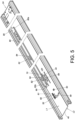
- FIG. 6 and FIG. 7 show the slide rail assembly 20 in a retracted state in which the second rail 24 is at a retracted position R with respect to the first rail 22 and the third rail 26 is retracted with respect to the second rail 24.
- the engaging member 44 stays in a first state S 1 in response to the elastic portion 78 of the elastic feature 74 applying an elastic force.
- the operating member 80 is at a first position P1, with the driving portion 88 (or more particularly its driving feature 88a) corresponding in position to the disengaging portion 72 of the engaging member 44.
- the working member 42 is supported by the second wall 46b of the third rail 26 and is thus kept in a first working state K1, in which the elastic structure 60 accumulates an elastic force.
- the working portion 52 of the working member 42 is offset in position from the two stops 32 and 34 in the height direction h2 shown in FIG. 3 .
- the first stop 32 and the second stop 34 define the receiving space X therebetween, but there is also a predetermined longitudinal distance between the first stop 32 and the blocking structure 36.
- the second rail 24 can be displaced with respect to the first rail 22 from the retracted position R in an opening direction D1.
- the working member 42 in the first working state K1 (i.e., with the working portion 52 of the working member 42 offset from the two stops 32 and 34 by a height difference H)
- the working portion 52 of the working member 42 can move past the second stop 34 and the first stop 32 in the opening direction D1 when the second rail 24 is displaced in the opening direction D1.
- there is a synchronization mechanism (not shown) that allows the second rail 24 and the third rail 26 to be displaced in unison in the opening direction D1.
- the blocking structure 36 of the first rail 22 blocks the second rail 24 through the engaging member 44 and thereby prevents the second rail 24 from being displaced with respect to the first rail 22 from the extended position E in a retracting direction D2.
- the blocking structure 36 includes a guiding section 92 and a blocking section 94 adjacent to the guiding section 92, wherein the guiding section 92 includes, for example, an inclined surface or a curved surface.
- the engaging portion 70 of the engaging member 44 is guided uphill by the guiding section 92 of the blocking structure 36 such that the elastic portion 78 of the elastic feature 74 accumulates an elastic force.
- the elastic portion 78 of the elastic feature 74 releases the elastic force accumulated therein to bring the engaging portion 70 of the engaging member 44 into engagement with the blocking section 94 of the blocking structure 36; wherein, the engaging member 44 is in the first state S 1, and the second rail 24 is at the extended position E.
- the second rail 24 in this state cannot be displaced with respect to the first rail 22 from the extended position E in the retracting direction D2.
- the third rail 26, on the other hand, can be further displaced in the opening direction D1 with respect to the second rail 24 at the extended position E to extend the slide rail assembly 20 even further.
- the working member 42 is switched from the first working state K1 to a second working state K2 by the elastic force released by the elastic structure 60.
- the working portion 52 of the working member 42 is no longer offset from the two stops 32 and 34 by the height difference H shown in FIG. 8 .
- the operating member 80 can be operated to drive the engaging member 44 and thereby free the engaging member 44 from blockage by the blocking structure 36. More specifically, a user may apply a force F to the operating member 80 to displace the operating member 80 from the first position P1 to a second position P2, the objective being for the driving portion 88 of the operating member 80 to switch the engaging member 44 from the first state S 1 to a second state S2 through contact with the disengaging portion 72 of the engaging member 44, thereby disengaging the engaging portion 70 of the engaging member 44 from the blocking section 94 of the blocking structure 36 (i.e., terminating the blocking relationship between the engaging member 44 and the blocking structure 36), allowing the second rail 24 to be displaced with respect to the first rail 22 from the extended position E in the retracting direction D2.
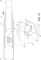
- the working portion 52 of the working member 42 comes into contact with the first guiding portion G1 of the first stop 32 of the first rail 22 (see FIG. 13 ). With the working portion 52 guided by the first guiding portion G1 of the first stop 32, the working member 42 is rotated through an angle such that the elastic structure 60 accumulates an elastic force (see FIG. 14 ).
- the working member 42 enters the second working state K2 (see FIG. 15 ) in response to the elastic structure 60 releasing the elastic force accumulated therein.
- the working portion 52 of the working member 42 ends up in the receiving space X and blocked between the first blocking portion B 1 of the first stop 32 and the second blocking portion B2 of the second stop 34.
- the first stop 32 blocks the second rail 24 through the working portion 52 of the working member 42 and thereby prevents the second rail 24 from being displaced from the predetermined position Y in the opening direction D1
- the second stop 34 blocks the second rail 24 through the working portion 52 of the working member 42 and thereby prevents the second rail 24 from being displaced from the predetermined position Y in the retracting direction D2.
- the front end f2 of the second rail 24 preferably extends a certain distance beyond the front end f1 of the first rail 22 so that, when it is desired to remount the third rail 26 after the third rail 26 is detached from the second channel of the second rail 24 in the opening direction D1, the user can easily align the rear end r3 of the third rail 26 with the corresponding channel opening of the second channel of the second rail 24 in order to insert the third rail 26 back into the second channel of the second rail 24. It is worth mentioning that the technical principle of detaching the third rail 26 from the second channel of the second rail 24 is comprehensible to a person of ordinary skill in the art and, for the sake of brevity therefore, will not be detailed herein.
- the working member 42 includes a guiding feature 96.
- the guiding feature 96 is, for example but not limited to, an inclined surface or a curved surface.
- the working member 42 can once again supported by the second wall 46b of the third rail 26 and kept in the first working state K1, with the elastic structure 60 accumulating an elastic force, and the working portion 52 of the working member 42 outside the receiving space X between the first stop 32 and the second stop 34.
- the second rail 24, therefore, can be displaced from the predetermined position Y in either of the retracting direction D2 and the opening direction D1.
- the second rail 24 and the third rail 26 can now be displaced in the retracting direction D2 to bring the slide rail assembly 20 back into the retracted state (see FIG. 6 ).
- the slide rail assembly 20 of the foregoing configuration can be used in a narrow space as shown in FIG. 18 and FIG. 19 , in which the slide rail assembly 20 is mounted on a rack and used in a particular environment.
- the front end f1 and the rear end r1 of the first rail 22 are mounted on a first post 95a and a second post 95b of the rack via a first bracket 91 and a second bracket 93 respectively.
- the third rail 26 serves to carry an object 97.
- the slide rail assembly 20 has a first length A1.
- the slide rail assembly 20 has a second length A2 shorter than the first length A1.
- the slide rail assembly 20 preferably has the following features:
Landscapes
- Drawers Of Furniture (AREA)
Claims (10)
- Ensemble de rails coulissants (20), caractérisé par le fait qu'il comprend :un premier rail (22),ledit premier rail (22) comprenant une première paroi (28a), une seconde paroi (28b) et une paroi longitudinale (30) raccordée entre la première paroi (28a) et la seconde paroi (28b) du premier rail (22), et un premier arrêt (32) et un second arrêt (34), tous les deux placés sur la paroi longitudinale (30) ; un deuxième rail (24) déplaçable longitudinalement par rapport au premier rail (22) ;et un élément fonctionnel (42) monté de manière mobile sur le deuxième rail (24) ;l'élément fonctionnel (42) est équipé d'une partie fonctionnelle (52), et lorsque le deuxième rail (24) est dans la position prédéterminée (Y) par rapport au premier rail (22), l'élément fonctionnel (42) est bloqué par le premier arrêt (32) via la partie fonctionnelle (52) et empêche ainsi le deuxième rail (24) de se déplacer depuis la position prédéterminée (Y) dans une direction d'ouverture (D1) ;le second arrêt (34) est placé sur le premier rail (22) de sorte que lorsque le deuxième rail (24) est dans la position prédéterminée (Y) par rapport au premier rail (22), l'élément fonctionnel (42) est bloqué par le second arrêt (34) via la partie fonctionnelle (52) et empêche ainsi le deuxième rail (24) de se déplacer depuis la position prédéterminée (Y) dans une direction de rétraction (D2) ;le deuxième rail (24), lorsqu'il atteint une position prédéterminée (Y) après un déplacement par rapport au premier rail (22) depuis une position déployée (E) dans la direction de rétraction (D2), est bloqué par le premier arrêt (32) via l'élément fonctionnel (42) et est ainsi empêché de se déplacer depuis la position prédéterminée (Y) dans la direction d'ouverture (D1) ;l'ensemble de rails coulissants (20) comporte une première longueur (A1) lorsque le deuxième rail (24) est dans la position déployée (E) ;l'ensemble de rails coulissants (20) comporte une seconde longueur (A2) plus courte que la première longueur (A1) lorsque le deuxième rail (24) est dans la position prédéterminée (Y) ;l'ensemble de rails coulissants (20) comprend en outre un troisième rail (26) déplaçable longitudinalement par rapport au deuxième rail (24), le deuxième rail (24) est monté de manière mobile entre le premier rail (22) et le troisième rail (26) ;le troisième rail (26) comprend une première paroi (46a), une seconde paroi (46b), et une paroi longitudinale (48) raccordée entre la première paroi (46a) et la seconde paroi (46b) du troisième rail (26) ;lorsque l'ensemble de rails coulissants (20) est dans un état rétracté dans lequel le deuxième rail (24) à une position rétractée (R) par rapport au premier rail (22) et le troisième rail (26) est rétracté par rapport au deuxième rail (24), l'élément fonctionnel (42) est supporté par la seconde paroi (46b) du troisième rail (26) et est ainsi maintenu dans un premier état de fonctionnement (K1), dans lequel une structure élastique (60) accumule une force élastique ;lorsque l'élément fonctionnel (42) est dans le premier état de fonctionnement (K1), la partie fonctionnelle (52) de l'élément fonctionnel (42) est décalée en position par rapport au premier arrêt (32) et au second arrêt (34) dans une direction en hauteur (h2) ; le deuxième rail (24) est configuré pour être déplacé par rapport au premier rail (22) depuis la position rétractée (R) dans la direction d'ouverture (D1) ;avec l'élément fonctionnel (42) dans le premier état de fonctionnement (K1), la partie fonctionnelle (52) de l'élément fonctionnel (42) est configurée pour se déplacer au-delà du second arrêt (34) et du premier arrêt (32) dans la direction d'ouverture (D1) lorsque le deuxième rail (24) est déplacé dans la direction d'ouverture (D1) ;il existe un mécanisme de synchronisation qui permet au deuxième rail (24) et au troisième rail (26) d'être déplacés à l'unisson dans la direction d'ouverture (D1) ;le premier état de fonctionnement (K1) est un état avec la partie fonctionnelle (52) de l'élément fonctionnel (42) décalée par rapport aux deux arrêts (32, 34) par une différence de hauteur (H) ;dès que la seconde paroi (46b) du troisième rail (26) cesse de supporter l'élément fonctionnel (42), l'élément fonctionnel (42) est configuré pour basculer depuis le premier état de fonctionnement (K1) vers le second état de fonctionnement (K2) par la force élastique libérée par la structure élastique (60) ; dans le second état de fonctionnement (K2), la partie fonctionnelle (52) de l'élément fonctionnel (42) n'est plus décalée par rapport aux deux arrêts (32, 34) par la différence de hauteur (H) ; le premier arrêt (32) et le second arrêt (34) définissent un espace de réception (X) entre eux.
- Ensemble de rails coulissants (20) selon la revendication 1, caractérisé par le fait que le deuxième rail (24) comprend une première paroi (38a), une seconde paroi (38b), et une paroi longitudinale (40) raccordée entre la première paroi (38a) et la seconde paroi (38b) du deuxième rail (24), et l'ensemble de rails coulissants (20) comprend en outre un axe (50) pour raccorder de manière pivotante l'élément fonctionnel (42) à la paroi longitudinale (40) du deuxième rail (24) dans une direction transversale (h1).
- Ensemble de rails coulissants (20) selon la revendication 2, caractérisé par le fait que la paroi longitudinale (40) du deuxième rail (24) comporte une première section de paroi de limitation de position (54), une seconde section de paroi de limitation de position (56), et un orifice d'extension (58) défini entre la première section de paroi de limitation de position (54) et la seconde section de paroi de limitation de position (56), et l'orifice d'extension (58) est configuré pour permettre le passage de la partie fonctionnelle (52) à travers celui-ci.
- Ensemble de rails coulissants (20) selon la revendication 1, caractérisé par le fait que la partie fonctionnelle (52) présente une configuration en colonne.
- Ensemble de rails coulissants (20) selon l'une quelconque des revendications 1-4, la structure élastique (60) applique la force élastique à l'élément fonctionnel (42).
- Ensemble de rails coulissants (20) selon l'une quelconque des revendications 1-5, caractérisé par le fait qu'il comprend en outre une structure de blocage (36) placée sur le premier rail (22) et un élément d'engagement (44) monté de manière mobile sur le deuxième rail (24) de sorte que, lorsqu'il atteint la position déployée (E) après un déplacement par rapport au premier rail (22) depuis la position rétractée (R) dans la direction d'ouverture (D1), le deuxième rail (24) est bloqué par la structure de blocage (36) via l'élément d'engagement (44) et est ainsi empêché de se déplacer depuis la position déployée (E) dans la direction de rétraction (D2).
- Ensemble de rails coulissants (20) selon la revendication 6, caractérisé par le fait que le deuxième rail (24), lorsqu'il atteint une position prédéterminée (Y) après un déplacement par rapport au premier rail (22) depuis la position déployée (E) dans la direction de rétraction (D2) après la fin du blocage entre l'élément d'engagement (44) et la structure de blocage (36), est bloqué par le premier arrêt (32) via l'élément fonctionnel (42) et est ainsi empêché de se déplacer depuis la position prédéterminée (Y) dans la direction d'ouverture (D 1).
- Ensemble de rails coulissants (20) selon la revendication 6 ou 7, caractérisé par le fait qu'il comprend en outre un élément de raccordement pivotant (68) pour raccorder de manière pivotante l'élément d'engagement (44) à la paroi longitudinale (40) du deuxième rail (24) dans la direction en hauteur (h2), la direction en hauteur (h2) est sensiblement perpendiculaire à la direction transversale (h1).
- Ensemble de rails coulissants (20) selon l'une quelconque des revendications 6-8, caractérisé par le fait qu'il comprend en outre une fonctionnalité élastique (74) pour appliquer une force élastique à l'élément d'engagement (44).
- Ensemble de rails coulissants (20) selon l'une quelconque des revendications 6-9, caractérisé par le fait qu'il comprend en outre un élément d'actionnement (80) placé sur l'un des premier rail (22) et deuxième rail (24), l'élément d'actionnement (80) est configuré pour être actionné afin d'entraîner l'élément d'engagement (44) et ainsi libérer l'élément d'engagement (44) du blocage par la structure de blocage (36).
Applications Claiming Priority (1)
| Application Number | Priority Date | Filing Date | Title |
|---|---|---|---|
| TW108139154A TWI704889B (zh) | 2019-10-28 | 2019-10-28 | 滑軌總成 |
Publications (2)
| Publication Number | Publication Date |
|---|---|
| EP3815575A1 EP3815575A1 (fr) | 2021-05-05 |
| EP3815575B1 true EP3815575B1 (fr) | 2024-08-14 |
Family
ID=70110075
Family Applications (1)
| Application Number | Title | Priority Date | Filing Date |
|---|---|---|---|
| EP20167075.9A Active EP3815575B1 (fr) | 2019-10-28 | 2020-03-31 | Ensemble rail coulissant |
Country Status (4)
| Country | Link |
|---|---|
| US (1) | US11246410B2 (fr) |
| EP (1) | EP3815575B1 (fr) |
| JP (1) | JP6941710B2 (fr) |
| TW (1) | TWI704889B (fr) |
Families Citing this family (14)
| Publication number | Priority date | Publication date | Assignee | Title |
|---|---|---|---|---|
| US11583078B2 (en) * | 2020-08-04 | 2023-02-21 | Accuride International, Inc. | Extendable drawer slide |
| TWI750987B (zh) | 2020-12-30 | 2021-12-21 | 川湖科技股份有限公司 | 滑軌總成 |
| CN114711572B (zh) * | 2021-01-04 | 2023-09-26 | 川湖科技股份有限公司 | 滑轨总成 |
| CN114847691B (zh) * | 2021-02-04 | 2023-11-24 | 川湖科技股份有限公司 | 滑轨总成 |
| US12004643B2 (en) * | 2022-07-13 | 2024-06-11 | Nan Juen International Co., Ltd. | Slide rail assembly |
| TWI800450B (zh) * | 2022-08-25 | 2023-04-21 | 振躍精密滑軌股份有限公司 | 伺服器滑軌之同步暨鎖定機構 |
| TWI826218B (zh) * | 2022-12-28 | 2023-12-11 | 川湖科技股份有限公司 | 滑軌總成 |
| TWI861654B (zh) * | 2022-12-28 | 2024-11-11 | 川湖科技股份有限公司 | 滑軌總成 |
| TWI835613B (zh) * | 2023-03-29 | 2024-03-11 | 富世達股份有限公司 | 滑軌裝置 |
| US12324515B2 (en) * | 2023-04-11 | 2025-06-10 | Martas Precision Slide Co., Ltd. | Middle and inner rails synchronization mechanism of slide rail |
| US12201214B2 (en) * | 2023-05-10 | 2025-01-21 | Martas Precision Slide Co., Ltd. | Frictional slide rail with synchronous middle and inner rails and lockable middle and outer rails |
| TWI829614B (zh) | 2023-08-04 | 2024-01-11 | 川湖科技股份有限公司 | 滑軌總成 |
| US12356578B2 (en) * | 2023-12-12 | 2025-07-08 | Martas Precision Slide Co., Ltd. | Aluminum extruded server slide rail |
| TWI856904B (zh) * | 2023-12-25 | 2024-09-21 | 川湖科技股份有限公司 | 滑軌總成 |
Family Cites Families (27)
| Publication number | Priority date | Publication date | Assignee | Title |
|---|---|---|---|---|
| US6935710B2 (en) | 2003-03-05 | 2005-08-30 | King Slide Works Co., Ltd. | Two-way retainer for a slide track assembly of drawers |
| US7404611B1 (en) | 2003-07-09 | 2008-07-29 | Central Industrial Supply Company | Pin and torsion spring lock for a drawer slide |
| US7413269B2 (en) | 2004-08-04 | 2008-08-19 | King Slide Works Co., Ltd. | Synchronous system for a three-stage ball bearing slide |
| GB2417191B (en) | 2004-08-19 | 2006-07-05 | King Slide Works Co Ltd | Releasable Retainer Within A Slide Structure |
| CN101327077B (zh) | 2007-06-22 | 2010-11-10 | 鸿富锦精密工业(深圳)有限公司 | 滑轨装置 |
| CN101332022B (zh) * | 2007-06-27 | 2010-11-10 | 鸿富锦精密工业(深圳)有限公司 | 滑轨装置 |
| CN102404962B (zh) * | 2010-09-13 | 2016-03-02 | 鸿富锦精密工业(深圳)有限公司 | 滑轨装置 |
| US8585164B2 (en) | 2011-06-02 | 2013-11-19 | King Slide Works Co., Ltd. | Locking mechanism of slide assembly |
| TWI590784B (zh) * | 2015-03-12 | 2017-07-11 | King Slide Works Co | 滑軌總成 |
| TWI601472B (zh) | 2015-04-13 | 2017-10-01 | King Slide Works Co Ltd | 滑軌總成 |
| US9498060B1 (en) * | 2015-06-10 | 2016-11-22 | Chi-Feng Hsu | Slide track assembly |
| TWI593341B (zh) | 2015-09-18 | 2017-07-21 | King Slide Works Co | 滑軌總成 |
| TWI568382B (zh) | 2016-01-22 | 2017-02-01 | 川湖科技股份有限公司 | 滑軌總成及其操作方法 |
| TWI629025B (zh) * | 2016-07-29 | 2018-07-11 | 川湖科技股份有限公司 | 滑軌總成 |
| TWI584761B (zh) * | 2016-09-13 | 2017-06-01 | 川湖科技股份有限公司 | 滑軌總成 |
| TWI665983B (zh) | 2017-04-12 | 2019-07-21 | 川湖科技股份有限公司 | 滑軌總成 |
| TWI629956B (zh) * | 2017-05-04 | 2018-07-21 | 川湖科技股份有限公司 | 滑軌總成 |
| TWI646924B (zh) * | 2017-09-20 | 2019-01-11 | 振躍精密滑軌股份有限公司 | 具有中軌解鎖功能的滑軌裝置 |
| TWI645807B (zh) * | 2017-12-28 | 2019-01-01 | 川湖科技股份有限公司 | 滑軌總成 |
| TWI670029B (zh) * | 2018-03-08 | 2019-09-01 | 川湖科技股份有限公司 | 滑軌總成 |
| TWI693042B (zh) * | 2018-07-19 | 2020-05-11 | 川湖科技股份有限公司 | 滑軌機構及其托架裝置 |
| TWI693044B (zh) * | 2018-07-27 | 2020-05-11 | 川湖科技股份有限公司 | 滑軌總成 |
| US10736422B2 (en) * | 2018-10-04 | 2020-08-11 | King Slide Works Co., Ltd. | Slide rail assembly |
| TWI681703B (zh) * | 2019-02-25 | 2020-01-01 | 川湖科技股份有限公司 | 滑軌機構及其支撐總成 |
| TWI700056B (zh) * | 2019-06-12 | 2020-08-01 | 川湖科技股份有限公司 | 滑軌總成 |
| TWI700057B (zh) * | 2019-06-12 | 2020-08-01 | 川湖科技股份有限公司 | 滑軌總成及其操作方法 |
| TWI706751B (zh) * | 2019-08-14 | 2020-10-11 | 川湖科技股份有限公司 | 滑軌總成 |
-
2019
- 2019-10-28 TW TW108139154A patent/TWI704889B/zh active
-
2020
- 2020-03-17 US US16/821,028 patent/US11246410B2/en active Active
- 2020-03-31 EP EP20167075.9A patent/EP3815575B1/fr active Active
- 2020-04-27 JP JP2020078021A patent/JP6941710B2/ja active Active
Also Published As
| Publication number | Publication date |
|---|---|
| TW202116224A (zh) | 2021-05-01 |
| TWI704889B (zh) | 2020-09-21 |
| JP2021065683A (ja) | 2021-04-30 |
| JP6941710B2 (ja) | 2021-09-29 |
| US11246410B2 (en) | 2022-02-15 |
| US20210120951A1 (en) | 2021-04-29 |
| EP3815575A1 (fr) | 2021-05-05 |
Similar Documents
| Publication | Publication Date | Title |
|---|---|---|
| EP3815575B1 (fr) | Ensemble rail coulissant | |
| EP3679833B1 (fr) | Ensemble de rail coulissant | |
| EP3082387B1 (fr) | Ensemble de rail de glissement | |
| EP3068199B1 (fr) | Ensemble de rail de glissement | |
| EP3750445B1 (fr) | Ensemble rail coulissant et son procédé de fonctionnement | |
| EP4035568B1 (fr) | Ensemble rail coulissant | |
| EP3808215B1 (fr) | Ensemble de glissières | |
| EP3777610B1 (fr) | Ensemble rail coulissant | |
| EP3735859B1 (fr) | Ensemble de rails coulissants | |
| EP3620080B1 (fr) | Ensemble de rails de glissement | |
| EP4164347B1 (fr) | Ensemble rail coulissant | |
| EP3750446A1 (fr) | Ensemble rail coulissant | |
| EP3461244B1 (fr) | Ensemble rail coulissant et son mécanisme de guidage | |
| TW202119978A (zh) | 滑軌總成 | |
| EP3960031B1 (fr) | Ensemble rail coulissant | |
| EP4501174A1 (fr) | Ensemble rail coulissant | |
| JP7410908B2 (ja) | スライドレールアセンブリとそのスライドレールキット | |
| CN112754197B (zh) | 滑轨总成 | |
| EP3804565B1 (fr) | Armoire et son kit de rail coulissant | |
| EP4529372A1 (fr) | Ensemble rail coulissant | |
| EP4563039B1 (fr) | Ensemble rail coulissant |
Legal Events
| Date | Code | Title | Description |
|---|---|---|---|
| PUAI | Public reference made under article 153(3) epc to a published international application that has entered the european phase |
Free format text: ORIGINAL CODE: 0009012 |
|
| STAA | Information on the status of an ep patent application or granted ep patent |
Free format text: STATUS: THE APPLICATION HAS BEEN PUBLISHED |
|
| AK | Designated contracting states |
Kind code of ref document: A1 Designated state(s): AL AT BE BG CH CY CZ DE DK EE ES FI FR GB GR HR HU IE IS IT LI LT LU LV MC MK MT NL NO PL PT RO RS SE SI SK SM TR |
|
| STAA | Information on the status of an ep patent application or granted ep patent |
Free format text: STATUS: REQUEST FOR EXAMINATION WAS MADE |
|
| 17P | Request for examination filed |
Effective date: 20210901 |
|
| RBV | Designated contracting states (corrected) |
Designated state(s): AL AT BE BG CH CY CZ DE DK EE ES FI FR GB GR HR HU IE IS IT LI LT LU LV MC MK MT NL NO PL PT RO RS SE SI SK SM TR |
|
| STAA | Information on the status of an ep patent application or granted ep patent |
Free format text: STATUS: EXAMINATION IS IN PROGRESS |
|
| 17Q | First examination report despatched |
Effective date: 20230414 |
|
| GRAP | Despatch of communication of intention to grant a patent |
Free format text: ORIGINAL CODE: EPIDOSNIGR1 |
|
| STAA | Information on the status of an ep patent application or granted ep patent |
Free format text: STATUS: GRANT OF PATENT IS INTENDED |
|
| INTG | Intention to grant announced |
Effective date: 20240415 |
|
| GRAS | Grant fee paid |
Free format text: ORIGINAL CODE: EPIDOSNIGR3 |
|
| GRAA | (expected) grant |
Free format text: ORIGINAL CODE: 0009210 |
|
| STAA | Information on the status of an ep patent application or granted ep patent |
Free format text: STATUS: THE PATENT HAS BEEN GRANTED |
|
| AK | Designated contracting states |
Kind code of ref document: B1 Designated state(s): AL AT BE BG CH CY CZ DE DK EE ES FI FR GB GR HR HU IE IS IT LI LT LU LV MC MK MT NL NO PL PT RO RS SE SI SK SM TR |
|
| REG | Reference to a national code |
Ref country code: GB Ref legal event code: FG4D |
|
| REG | Reference to a national code |
Ref country code: CH Ref legal event code: EP |
|
| REG | Reference to a national code |
Ref country code: DE Ref legal event code: R096 Ref document number: 602020035608 Country of ref document: DE |
|
| REG | Reference to a national code |
Ref country code: IE Ref legal event code: FG4D |
|
| REG | Reference to a national code |
Ref country code: LT Ref legal event code: MG9D |
|
| REG | Reference to a national code |
Ref country code: NL Ref legal event code: MP Effective date: 20240814 |
|
| PG25 | Lapsed in a contracting state [announced via postgrant information from national office to epo] |
Ref country code: NO Free format text: LAPSE BECAUSE OF FAILURE TO SUBMIT A TRANSLATION OF THE DESCRIPTION OR TO PAY THE FEE WITHIN THE PRESCRIBED TIME-LIMIT Effective date: 20241114 |
|
| REG | Reference to a national code |
Ref country code: AT Ref legal event code: MK05 Ref document number: 1712436 Country of ref document: AT Kind code of ref document: T Effective date: 20240814 |
|
| PG25 | Lapsed in a contracting state [announced via postgrant information from national office to epo] |
Ref country code: FI Free format text: LAPSE BECAUSE OF FAILURE TO SUBMIT A TRANSLATION OF THE DESCRIPTION OR TO PAY THE FEE WITHIN THE PRESCRIBED TIME-LIMIT Effective date: 20240814 Ref country code: NL Free format text: LAPSE BECAUSE OF FAILURE TO SUBMIT A TRANSLATION OF THE DESCRIPTION OR TO PAY THE FEE WITHIN THE PRESCRIBED TIME-LIMIT Effective date: 20240814 Ref country code: PT Free format text: LAPSE BECAUSE OF FAILURE TO SUBMIT A TRANSLATION OF THE DESCRIPTION OR TO PAY THE FEE WITHIN THE PRESCRIBED TIME-LIMIT Effective date: 20241216 Ref country code: PL Free format text: LAPSE BECAUSE OF FAILURE TO SUBMIT A TRANSLATION OF THE DESCRIPTION OR TO PAY THE FEE WITHIN THE PRESCRIBED TIME-LIMIT Effective date: 20240814 Ref country code: GR Free format text: LAPSE BECAUSE OF FAILURE TO SUBMIT A TRANSLATION OF THE DESCRIPTION OR TO PAY THE FEE WITHIN THE PRESCRIBED TIME-LIMIT Effective date: 20241115 |
|
| PG25 | Lapsed in a contracting state [announced via postgrant information from national office to epo] |
Ref country code: BG Free format text: LAPSE BECAUSE OF FAILURE TO SUBMIT A TRANSLATION OF THE DESCRIPTION OR TO PAY THE FEE WITHIN THE PRESCRIBED TIME-LIMIT Effective date: 20240814 |
|
| PG25 | Lapsed in a contracting state [announced via postgrant information from national office to epo] |
Ref country code: LV Free format text: LAPSE BECAUSE OF FAILURE TO SUBMIT A TRANSLATION OF THE DESCRIPTION OR TO PAY THE FEE WITHIN THE PRESCRIBED TIME-LIMIT Effective date: 20240814 |
|
| PG25 | Lapsed in a contracting state [announced via postgrant information from national office to epo] |
Ref country code: AT Free format text: LAPSE BECAUSE OF FAILURE TO SUBMIT A TRANSLATION OF THE DESCRIPTION OR TO PAY THE FEE WITHIN THE PRESCRIBED TIME-LIMIT Effective date: 20240814 Ref country code: IS Free format text: LAPSE BECAUSE OF FAILURE TO SUBMIT A TRANSLATION OF THE DESCRIPTION OR TO PAY THE FEE WITHIN THE PRESCRIBED TIME-LIMIT Effective date: 20241214 |
|
| PG25 | Lapsed in a contracting state [announced via postgrant information from national office to epo] |
Ref country code: HR Free format text: LAPSE BECAUSE OF FAILURE TO SUBMIT A TRANSLATION OF THE DESCRIPTION OR TO PAY THE FEE WITHIN THE PRESCRIBED TIME-LIMIT Effective date: 20240814 |
|
| PG25 | Lapsed in a contracting state [announced via postgrant information from national office to epo] |
Ref country code: ES Free format text: LAPSE BECAUSE OF FAILURE TO SUBMIT A TRANSLATION OF THE DESCRIPTION OR TO PAY THE FEE WITHIN THE PRESCRIBED TIME-LIMIT Effective date: 20240814 Ref country code: RS Free format text: LAPSE BECAUSE OF FAILURE TO SUBMIT A TRANSLATION OF THE DESCRIPTION OR TO PAY THE FEE WITHIN THE PRESCRIBED TIME-LIMIT Effective date: 20241114 |
|
| PG25 | Lapsed in a contracting state [announced via postgrant information from national office to epo] |
Ref country code: RS Free format text: LAPSE BECAUSE OF FAILURE TO SUBMIT A TRANSLATION OF THE DESCRIPTION OR TO PAY THE FEE WITHIN THE PRESCRIBED TIME-LIMIT Effective date: 20241114 Ref country code: PT Free format text: LAPSE BECAUSE OF FAILURE TO SUBMIT A TRANSLATION OF THE DESCRIPTION OR TO PAY THE FEE WITHIN THE PRESCRIBED TIME-LIMIT Effective date: 20241216 Ref country code: PL Free format text: LAPSE BECAUSE OF FAILURE TO SUBMIT A TRANSLATION OF THE DESCRIPTION OR TO PAY THE FEE WITHIN THE PRESCRIBED TIME-LIMIT Effective date: 20240814 Ref country code: NO Free format text: LAPSE BECAUSE OF FAILURE TO SUBMIT A TRANSLATION OF THE DESCRIPTION OR TO PAY THE FEE WITHIN THE PRESCRIBED TIME-LIMIT Effective date: 20241114 Ref country code: NL Free format text: LAPSE BECAUSE OF FAILURE TO SUBMIT A TRANSLATION OF THE DESCRIPTION OR TO PAY THE FEE WITHIN THE PRESCRIBED TIME-LIMIT Effective date: 20240814 Ref country code: LV Free format text: LAPSE BECAUSE OF FAILURE TO SUBMIT A TRANSLATION OF THE DESCRIPTION OR TO PAY THE FEE WITHIN THE PRESCRIBED TIME-LIMIT Effective date: 20240814 Ref country code: IS Free format text: LAPSE BECAUSE OF FAILURE TO SUBMIT A TRANSLATION OF THE DESCRIPTION OR TO PAY THE FEE WITHIN THE PRESCRIBED TIME-LIMIT Effective date: 20241214 Ref country code: HR Free format text: LAPSE BECAUSE OF FAILURE TO SUBMIT A TRANSLATION OF THE DESCRIPTION OR TO PAY THE FEE WITHIN THE PRESCRIBED TIME-LIMIT Effective date: 20240814 Ref country code: GR Free format text: LAPSE BECAUSE OF FAILURE TO SUBMIT A TRANSLATION OF THE DESCRIPTION OR TO PAY THE FEE WITHIN THE PRESCRIBED TIME-LIMIT Effective date: 20241115 Ref country code: FI Free format text: LAPSE BECAUSE OF FAILURE TO SUBMIT A TRANSLATION OF THE DESCRIPTION OR TO PAY THE FEE WITHIN THE PRESCRIBED TIME-LIMIT Effective date: 20240814 Ref country code: ES Free format text: LAPSE BECAUSE OF FAILURE TO SUBMIT A TRANSLATION OF THE DESCRIPTION OR TO PAY THE FEE WITHIN THE PRESCRIBED TIME-LIMIT Effective date: 20240814 Ref country code: BG Free format text: LAPSE BECAUSE OF FAILURE TO SUBMIT A TRANSLATION OF THE DESCRIPTION OR TO PAY THE FEE WITHIN THE PRESCRIBED TIME-LIMIT Effective date: 20240814 Ref country code: AT Free format text: LAPSE BECAUSE OF FAILURE TO SUBMIT A TRANSLATION OF THE DESCRIPTION OR TO PAY THE FEE WITHIN THE PRESCRIBED TIME-LIMIT Effective date: 20240814 |
|
| PG25 | Lapsed in a contracting state [announced via postgrant information from national office to epo] |
Ref country code: DK Free format text: LAPSE BECAUSE OF FAILURE TO SUBMIT A TRANSLATION OF THE DESCRIPTION OR TO PAY THE FEE WITHIN THE PRESCRIBED TIME-LIMIT Effective date: 20240814 Ref country code: RO Free format text: LAPSE BECAUSE OF FAILURE TO SUBMIT A TRANSLATION OF THE DESCRIPTION OR TO PAY THE FEE WITHIN THE PRESCRIBED TIME-LIMIT Effective date: 20240814 Ref country code: SM Free format text: LAPSE BECAUSE OF FAILURE TO SUBMIT A TRANSLATION OF THE DESCRIPTION OR TO PAY THE FEE WITHIN THE PRESCRIBED TIME-LIMIT Effective date: 20240814 |
|
| PG25 | Lapsed in a contracting state [announced via postgrant information from national office to epo] |
Ref country code: EE Free format text: LAPSE BECAUSE OF FAILURE TO SUBMIT A TRANSLATION OF THE DESCRIPTION OR TO PAY THE FEE WITHIN THE PRESCRIBED TIME-LIMIT Effective date: 20240814 |
|
| PG25 | Lapsed in a contracting state [announced via postgrant information from national office to epo] |
Ref country code: CZ Free format text: LAPSE BECAUSE OF FAILURE TO SUBMIT A TRANSLATION OF THE DESCRIPTION OR TO PAY THE FEE WITHIN THE PRESCRIBED TIME-LIMIT Effective date: 20240814 |
|
| PG25 | Lapsed in a contracting state [announced via postgrant information from national office to epo] |
Ref country code: IT Free format text: LAPSE BECAUSE OF FAILURE TO SUBMIT A TRANSLATION OF THE DESCRIPTION OR TO PAY THE FEE WITHIN THE PRESCRIBED TIME-LIMIT Effective date: 20240814 Ref country code: SK Free format text: LAPSE BECAUSE OF FAILURE TO SUBMIT A TRANSLATION OF THE DESCRIPTION OR TO PAY THE FEE WITHIN THE PRESCRIBED TIME-LIMIT Effective date: 20240814 |
|
| REG | Reference to a national code |
Ref country code: DE Ref legal event code: R097 Ref document number: 602020035608 Country of ref document: DE |
|
| PLBE | No opposition filed within time limit |
Free format text: ORIGINAL CODE: 0009261 |
|
| STAA | Information on the status of an ep patent application or granted ep patent |
Free format text: STATUS: NO OPPOSITION FILED WITHIN TIME LIMIT |
|
| 26N | No opposition filed |
Effective date: 20250515 |
|
| PG25 | Lapsed in a contracting state [announced via postgrant information from national office to epo] |
Ref country code: SE Free format text: LAPSE BECAUSE OF FAILURE TO SUBMIT A TRANSLATION OF THE DESCRIPTION OR TO PAY THE FEE WITHIN THE PRESCRIBED TIME-LIMIT Effective date: 20240814 |
|
| PG25 | Lapsed in a contracting state [announced via postgrant information from national office to epo] |
Ref country code: MC Free format text: LAPSE BECAUSE OF FAILURE TO SUBMIT A TRANSLATION OF THE DESCRIPTION OR TO PAY THE FEE WITHIN THE PRESCRIBED TIME-LIMIT Effective date: 20240814 |
|
| REG | Reference to a national code |
Ref country code: CH Ref legal event code: H13 Free format text: ST27 STATUS EVENT CODE: U-0-0-H10-H13 (AS PROVIDED BY THE NATIONAL OFFICE) Effective date: 20251023 |
|
| PG25 | Lapsed in a contracting state [announced via postgrant information from national office to epo] |
Ref country code: LU Free format text: LAPSE BECAUSE OF NON-PAYMENT OF DUE FEES Effective date: 20250331 |
|
| REG | Reference to a national code |
Ref country code: BE Ref legal event code: MM Effective date: 20250331 |
|
| PG25 | Lapsed in a contracting state [announced via postgrant information from national office to epo] |
Ref country code: FR Free format text: LAPSE BECAUSE OF NON-PAYMENT OF DUE FEES Effective date: 20250331 |
|
| PG25 | Lapsed in a contracting state [announced via postgrant information from national office to epo] |
Ref country code: BE Free format text: LAPSE BECAUSE OF NON-PAYMENT OF DUE FEES Effective date: 20250331 |
|
| PG25 | Lapsed in a contracting state [announced via postgrant information from national office to epo] |
Ref country code: CH Free format text: LAPSE BECAUSE OF NON-PAYMENT OF DUE FEES Effective date: 20250331 |
|
| PGFP | Annual fee paid to national office [announced via postgrant information from national office to epo] |
Ref country code: GB Payment date: 20260108 Year of fee payment: 7 |
|
| PGFP | Annual fee paid to national office [announced via postgrant information from national office to epo] |
Ref country code: DE Payment date: 20260109 Year of fee payment: 7 Ref country code: IE Payment date: 20260108 Year of fee payment: 7 |