EP3815741A1 - Dispositif de photothérapie de type chaise - Google Patents
Dispositif de photothérapie de type chaise Download PDFInfo
- Publication number
- EP3815741A1 EP3815741A1 EP19825986.3A EP19825986A EP3815741A1 EP 3815741 A1 EP3815741 A1 EP 3815741A1 EP 19825986 A EP19825986 A EP 19825986A EP 3815741 A1 EP3815741 A1 EP 3815741A1
- Authority
- EP
- European Patent Office
- Prior art keywords
- radiation
- module
- chair
- phototherapy device
- patient
- Prior art date
- Legal status (The legal status is an assumption and is not a legal conclusion. Google has not performed a legal analysis and makes no representation as to the accuracy of the status listed.)
- Granted
Links
Images




Classifications
-
- A—HUMAN NECESSITIES
- A61—MEDICAL OR VETERINARY SCIENCE; HYGIENE
- A61N—ELECTROTHERAPY; MAGNETOTHERAPY; RADIATION THERAPY; ULTRASOUND THERAPY
- A61N5/00—Radiation therapy
- A61N5/06—Radiation therapy using light
- A61N5/0613—Apparatus adapted for a specific treatment
- A61N5/0622—Optical stimulation for exciting neural tissue
-
- A—HUMAN NECESSITIES
- A61—MEDICAL OR VETERINARY SCIENCE; HYGIENE
- A61N—ELECTROTHERAPY; MAGNETOTHERAPY; RADIATION THERAPY; ULTRASOUND THERAPY
- A61N5/00—Radiation therapy
- A61N5/06—Radiation therapy using light
-
- A—HUMAN NECESSITIES
- A61—MEDICAL OR VETERINARY SCIENCE; HYGIENE
- A61B—DIAGNOSIS; SURGERY; IDENTIFICATION
- A61B5/00—Measuring for diagnostic purposes; Identification of persons
- A61B5/0059—Measuring for diagnostic purposes; Identification of persons using light, e.g. diagnosis by transillumination, diascopy, fluorescence
- A61B5/0077—Devices for viewing the surface of the body, e.g. camera, magnifying lens
-
- A—HUMAN NECESSITIES
- A61—MEDICAL OR VETERINARY SCIENCE; HYGIENE
- A61B—DIAGNOSIS; SURGERY; IDENTIFICATION
- A61B5/00—Measuring for diagnostic purposes; Identification of persons
- A61B5/48—Other medical applications
- A61B5/4836—Diagnosis combined with treatment in closed-loop systems or methods
-
- A—HUMAN NECESSITIES
- A61—MEDICAL OR VETERINARY SCIENCE; HYGIENE
- A61B—DIAGNOSIS; SURGERY; IDENTIFICATION
- A61B5/00—Measuring for diagnostic purposes; Identification of persons
- A61B5/68—Arrangements of detecting, measuring or recording means, e.g. sensors, in relation to patient
- A61B5/6887—Arrangements of detecting, measuring or recording means, e.g. sensors, in relation to patient mounted on external non-worn devices, e.g. non-medical devices
- A61B5/6891—Furniture
-
- A—HUMAN NECESSITIES
- A61—MEDICAL OR VETERINARY SCIENCE; HYGIENE
- A61B—DIAGNOSIS; SURGERY; IDENTIFICATION
- A61B5/00—Measuring for diagnostic purposes; Identification of persons
- A61B5/74—Details of notification to user or communication with user or patient; User input means
- A61B5/742—Details of notification to user or communication with user or patient; User input means using visual displays
- A61B5/7425—Displaying combinations of multiple images regardless of image source, e.g. displaying a reference anatomical image with a live image
-
- A—HUMAN NECESSITIES
- A61—MEDICAL OR VETERINARY SCIENCE; HYGIENE
- A61G—TRANSPORT, PERSONAL CONVEYANCES, OR ACCOMMODATION SPECIALLY ADAPTED FOR PATIENTS OR DISABLED PERSONS; OPERATING TABLES OR CHAIRS; CHAIRS FOR DENTISTRY; FUNERAL DEVICES
- A61G15/00—Operating chairs; Dental chairs; Accessories specially adapted therefor, e.g. work stands
- A61G15/007—Physiotherapeutic chairs
-
- A—HUMAN NECESSITIES
- A61—MEDICAL OR VETERINARY SCIENCE; HYGIENE
- A61N—ELECTROTHERAPY; MAGNETOTHERAPY; RADIATION THERAPY; ULTRASOUND THERAPY
- A61N5/00—Radiation therapy
- A61N5/06—Radiation therapy using light
- A61N5/0613—Apparatus adapted for a specific treatment
-
- A—HUMAN NECESSITIES
- A61—MEDICAL OR VETERINARY SCIENCE; HYGIENE
- A61B—DIAGNOSIS; SURGERY; IDENTIFICATION
- A61B2560/00—Constructional details of operational features of apparatus; Accessories for medical measuring apparatus
- A61B2560/02—Operational features
- A61B2560/029—Operational features adapted for auto-initiation
-
- A—HUMAN NECESSITIES
- A61—MEDICAL OR VETERINARY SCIENCE; HYGIENE
- A61B—DIAGNOSIS; SURGERY; IDENTIFICATION
- A61B90/00—Instruments, implements or accessories specially adapted for surgery or diagnosis and not covered by any of the groups A61B1/00 - A61B50/00, e.g. for luxation treatment or for protecting wound edges
- A61B90/36—Image-producing devices or illumination devices not otherwise provided for
- A61B90/361—Image-producing devices, e.g. surgical cameras
-
- A—HUMAN NECESSITIES
- A61—MEDICAL OR VETERINARY SCIENCE; HYGIENE
- A61G—TRANSPORT, PERSONAL CONVEYANCES, OR ACCOMMODATION SPECIALLY ADAPTED FOR PATIENTS OR DISABLED PERSONS; OPERATING TABLES OR CHAIRS; CHAIRS FOR DENTISTRY; FUNERAL DEVICES
- A61G2210/00—Devices for specific treatment or diagnosis
-
- A—HUMAN NECESSITIES
- A61—MEDICAL OR VETERINARY SCIENCE; HYGIENE
- A61N—ELECTROTHERAPY; MAGNETOTHERAPY; RADIATION THERAPY; ULTRASOUND THERAPY
- A61N5/00—Radiation therapy
- A61N5/06—Radiation therapy using light
- A61N2005/0626—Monitoring, verifying, controlling systems and methods
-
- A—HUMAN NECESSITIES
- A61—MEDICAL OR VETERINARY SCIENCE; HYGIENE
- A61N—ELECTROTHERAPY; MAGNETOTHERAPY; RADIATION THERAPY; ULTRASOUND THERAPY
- A61N5/00—Radiation therapy
- A61N5/06—Radiation therapy using light
- A61N2005/0632—Constructional aspects of the apparatus
-
- A—HUMAN NECESSITIES
- A61—MEDICAL OR VETERINARY SCIENCE; HYGIENE
- A61N—ELECTROTHERAPY; MAGNETOTHERAPY; RADIATION THERAPY; ULTRASOUND THERAPY
- A61N5/00—Radiation therapy
- A61N5/06—Radiation therapy using light
- A61N2005/0635—Radiation therapy using light characterised by the body area to be irradiated
- A61N2005/0643—Applicators, probes irradiating specific body areas in close proximity
-
- A—HUMAN NECESSITIES
- A61—MEDICAL OR VETERINARY SCIENCE; HYGIENE
- A61N—ELECTROTHERAPY; MAGNETOTHERAPY; RADIATION THERAPY; ULTRASOUND THERAPY
- A61N5/00—Radiation therapy
- A61N5/06—Radiation therapy using light
- A61N2005/065—Light sources therefor
- A61N2005/0651—Diodes
- A61N2005/0652—Arrays of diodes
-
- A—HUMAN NECESSITIES
- A61—MEDICAL OR VETERINARY SCIENCE; HYGIENE
- A61N—ELECTROTHERAPY; MAGNETOTHERAPY; RADIATION THERAPY; ULTRASOUND THERAPY
- A61N5/00—Radiation therapy
- A61N5/06—Radiation therapy using light
- A61N2005/0658—Radiation therapy using light characterised by the wavelength of light used
- A61N2005/0659—Radiation therapy using light characterised by the wavelength of light used infrared
- A61N2005/066—Radiation therapy using light characterised by the wavelength of light used infrared far infrared
-
- A—HUMAN NECESSITIES
- A61—MEDICAL OR VETERINARY SCIENCE; HYGIENE
- A61N—ELECTROTHERAPY; MAGNETOTHERAPY; RADIATION THERAPY; ULTRASOUND THERAPY
- A61N5/00—Radiation therapy
- A61N5/01—Devices for producing movement of radiation source during therapy
Definitions
- the present invention relates to a chair-type phototherapy device.
- Phototherapy devices that apply, for example, infrared rays (wavelengths of approximately 700 nm to 2500 nm) as treatment light targeted at an affected area or an acupressure point through the skin have been used for treatment such as relief of aching pain. It has recently been revealed that radiation of light has various actions on nerves, such as selective suppression of nerve conduction in sensory fibers that transmit pain in peripheral nervous systems, suppression of pain-producing substances, and tension relaxation of sympathetic nerves. Among light rays, laser light is widely used in these applications since a specific wavelength can be emitted with high power.
- PTL 1 describes treatment of dysuria, in which dysuria is treated by applying laser light through the skin, targeted at the sacral foramina where bladder sensory nerves exist, in order to suppress abnormal activities of sensory nerves in the bladder.
- repeatedly irradiating a given site such as an affected area and an acupressure point is an important factor for achieving the maximum effect. It is desirable that patients perform light irradiation by themselves at home because light irradiation for a few minutes to a few tens of minutes per day need to be repeated at a frequency of twice a week to everyday.
- PTL 2 Conventional photoirradiation methods for affected areas are described in PTL 2 in which a laser radiation probe is held in hand and brought into contact with an affected area and in PTL 3 in which an arm extending from a therapeutic device body is moved to a desired position and a radiation probe fixed to the tip end of the arm is used.
- a patient performs light irradiation by aligning an irradiation position by himself/herself on the back region such as the back and the waist to irradiate the sacral foramina with bladder sensory nerves or the spinal ganglion corresponding to a pain-causing site with light through the skin.
- Light irradiation to an accurate position is required to obtain sufficient therapeutic effects.
- the patient undergoes a marking on a treatment site at hospital in advance and performs light irradiation by aligning an irradiation position of a device with the marking, thereby achieving effective phototherapy.
- the patient In the configuration of the therapeutic device in which a laser light radiation probe is held in hand and brought into contact as disclosed in PTL 2, the patient is supposed to put the arm around the back region by himself/herself and hold the radiation probe at an appropriate position in an unnatural posture for a few minutes to a few tens of minutes.
- the patient may perform phototherapy on the patient's back region in a seated state without putting the arm around the back, by adjusting the position of the arm and arranging the radiation probe on the back region.
- the arm may be moved and thus the irradiation position may be displaced during therapy, resulting in insufficient therapeutic effects.
- the patient therefore has to always maintain the same posture so as not lean on the arm, and this is far from a treatment in a comfortable position. If the treatment is unable to be performed in a comfortable posture, the burden of treatment on the patient increases to make it difficult to continue the treatment, and sufficient therapeutic effects fail to be achieved.
- the device When the device is equipped with a rotating mechanism and an expansion mechanism for freely moving the arm and a support mechanism for fixing them, the device becomes large and heavy in weight and difficult to use in a limited space such as at home.
- An object of the present invention is then to provide a chair-type phototherapy device that enables a patient to perform light irradiation accurately targeted at a treatment site in a seated position on a chair and consequently achieves effective phototherapy even when the treatment site is in the back region that the patient is unable to see, for example, as in light irradiation for dysuria patients and patients with pain, and the patient performs light irradiation by himself/herself at home.
- the present invention provides a chair-type phototherapy device having a seat on which a patient is seated.
- the chair-type phototherapy device includes a radiation module configured to emit radiation light toward a living body, a drive module positioned behind the patient for moving the radiation module, and a fixing module fixing the drive module to the seat.
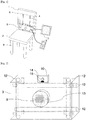
- the chair-type phototherapy device 1 in the present embodiment is a device for performing dysuria treatment and pain treatment by irradiating the position of the sacral foramina and the ganglion of a patient with light rays.
- the chair-type phototherapy device 1 includes a seat 2 on which the patient is seated, a radiation module 3, a drive module 4, and a fixing module 5.
- the seat 2 has a size enough for one patient to sit on and has a substantially rectangular or substantially circular shape.
- the material of the seat 2 is, for example, leather or fiber for its surface, with the inside stuffed with a cushion material such as urethane and with a frame made of metal, resin, wood, or the like.
- a plurality of legs 6 are provided under the seat 2.
- the fixing module 5 is shaped like a rectangular or square frame and holds and fixes the drive module 4 in the inside.
- the fixing module 5 is attached upright from the seat 2 at one end of the seat 2 of the chair and is arranged behind the back of the patient.
- the fixing module 5 is formed of metal, resin, wood, or the like to ensure the strength and enables the patient to perform treatment while leaning against it.
- the fixing module 5 is not necessarily directly fixed to the seat 2 as long as its relative position to the seat 2 is fixed.
- the fixing module 5 may be fixed to the chair legs 6 connected to the seat 2.
- the fixing module 5 may be configured separately from the backrest of the chair.
- the radiation module 3 for irradiating the patient with light rays and the drive module 4 for changing the position of the radiation module 3 are provided.
- the drive module 4 can be actuated in the fixing module 5 to move the radiation module 3 to a given position.
- a monitor 7 is connected to the radiation module 3 to display an image in the surrounding of the treatment site.
- the present chair-type phototherapy device 1 may include a remote controller 8 for irradiation control to enable light irradiation while the patient keeps a seated position.
- the remote controller 8 for irradiation control is connected to a casing 11 of the radiation module 3 through a not-illustrated light emission control unit via a cable and is supplied with electricity from a not-illustrated power source.
- the remote controller 8 for radiation control transmits a signal to the light emission control unit based on an input by the patient operating a switch on the remote controller 8 for radiation control, and the light emission control unit controls light irradiation from a radiation probe 9. For example, switching between oscillation and stop of light from the radiation probe 9 is performed.
- the patient thus can switch radiation in a seated position, prevent erroneous irradiation to a site other than the treatment site, and perform safe phototherapy.
- Fig. 2 is a diagram illustrating the radiation module 3.
- the radiation module 3 includes the radiation probe 9, an observation module 10 for grasping a treatment site in the back region of the patient and an irradiation position of irradiation light, and the casing 11.
- the casing 11 is a box having any shape for holding the radiation probe 9 and the observation module 10. In the horizontal direction and the vertical direction of the casing 11, any given number of through holes 12 are provided, and the through holes 12 are provided with lateral holes orthogonal to the through holes 12. The through holes 12 and the lateral holes will be described later.
- the casing 11 contains a not-illustrated built-in power source such as a battery for supplying electricity to the above-noted remote controller 8 for radiation control as well as the radiation module 3, the observation module 10, and the monitor 7.
- the power source may be provided outside of the casing 11, and the power source may include switching or other circuits. In this case, the power source is connected to the radiation module 3, the observation module 10, the monitor 7, and the remote controller 8 for radiation control by wire.
- the radiation probe 9 is connected substantially to the center of the casing 11.
- the radiation probe 9 is a member for radiating light rays toward a given position on the patient's skin and is formed of metal, resin, or the like in the shape of a hollow cylinder.
- the shape of the radiation probe 9 is not necessarily cylindrical.
- a treatment light source 13 is provided inside the radiation probe 9.
- a laser, an LED, a halogen lamp, and a xenon lamp can be used as the treatment light source 13.
- the treatment light source 13 may be installed outside the radiation probe 9 and the light may be guided to the radiation probe 9 through a light guide path such as an optical fiber.
- the radiation probe 9 is fixed to the casing 11 so as to protrude from the casing 11 toward the patient. Since body shapes may vary among patients, it is preferable that the radiation probe 9 and the casing 11 are constructed such that the fixed position of the radiation probe 9 relative to the casing 11 can be adjusted, enabling to adjust the amount of protrusion of the radiation probe 9 so that the radiation probe 9 is in contact with an irradiation site without uncomfortable feeling when the patient is seated.
- the casing 11 has a hole receiving the radiation probe 9 substantially at the center of a surface facing the patient, and the amount of protrusion of the radiation probe 9 is adjusted by fitting the radiation probe 9 in the hole and changing its attachment position.
- the casing 11 and the radiation probe 9 are connected through a ratchet mechanism such that the radiation probe 9 is movable only toward the back of the patient relative to the casing 11 and the movement in the opposite direction is restricted.
- This configuration can prevent dropping of the radiation probe 9 from the casing 11 even when the patient leans deeply against the radiation module 3 to push the radiation probe 9 in strongly.
- a rack and pinion mechanism may be used instead of the ratchet mechanism.
- the observation module 10 is connected to the top portion of the casing 11.
- the observation module 10 includes a camera 14 and an illumination light source 15.
- the camera 14 is a member for grasping a treatment site and an irradiation position of radiation light in the back region of the patient.
- a CCD camera, a CMOS camera, and the like can be used as the camera 14.
- the illumination light source 15 is a member for illuminating a field of observation of the camera 14 and capturing a sharp image.
- An LED, a fluorescent lamp, and the like can be used as the illumination light source 15.
- the observation module 10 may be installed at any position in the casing 11 as long as the treatment site of the patient and the position of radiation light can be observed by the camera 14.
- the image captured by the camera 14 appears on the monitor 7.
- the monitor 7 may be connected to the observation module 10 by wire or may be configured separately from the observation module 10 and connected to the observation module 10 through a known wireless communication technique.
- Fig. 3 is a diagram illustrating the drive module 4.
- the drive module 4 includes four sliders 16 and at least two of linear guide 17 and linear guide 18 for two axial directions of X and Y: the X axis substantially in the horizontal direction and the Y axis direction orthogonal to the X axis.
- the linear guide 17 and the linear guide 18 are arranged in any two axial directions orthogonal to each other in the same plane, and the sliders 16 are disposed orthogonally to the linear guides 17 at both ends of the linear guides 17 and the linear guides 18.
- the sliders 16 each include rotation axes 19 and a belt 20 and are disposed in the inside of four sides of the frame-like fixing module 5.
- the rotation axes 19 are fixed to the fixing module 5.
- the belt 20 is a strip-like member formed of metal, resin, rubber, or the like wound around at least two rotation axes 19 and is arranged to turn around the rotation axes 19.
- the belt 20 may be, for example, a mechanism such as a rail or a ball screw extending in one direction in one or both of the X-axis direction and the Y-axis direction.
- the linear guides 17 and the linear guides 18 are rod-like members formed of metal, resin, or the like fixed to the belt 20. When the belt 20 rotates in the fixing module 5, the linear guides 17 fixed to the belt 20 move in accordance with the rotation of the belt 20. The linear guides 17 thus can move in orthogonal two axial directions in the fixing module 5.
- Fig. 4 is a top view of the radiation module 3 in a state in which the radiation module 3 and the linear guides 17 are connected.
- the linear guides 17 are inserted slidably into the through holes 12 provided in the casing 11.
- Bolts 21 are inserted into the lateral holes to fix or release the linear guides 17 to/from the casing 11.
- the bolts 21 may be fasteners such as fixing pins, wing screws, and clamps.
- the radiation module 3 thus can be moved in the X-axis direction while the position in the Y-axis direction is fixed. Subsequently, the bolts 21 in the linear guides 17 in the X-axis direction are fixed, the bolts 21 in the linear guides 18 in the Y-axis direction are released, and the radiation module 3 is moved in the Y-axis direction while the position in the X-axis direction is fixed. With this configuration, the radiation module 3 can be moved to any position in the fixing module 5.
- the configuration of the drive module 4 is not limited to the embodiment described above.
- the following mechanism may be adopted, wherein an arm rotatable in a desired direction is attached in the vicinity of a joint section of the fixing module 5 and the seat 2, and the radiation probe 9 is attached to a tip of the arm to position the radiation probe 9 in any position in the fixing module 5.
- the following configuration may be adopted, wherein a motor is built in the rotation axis 19 to enable rotary drive, the rotation axis 19 is engaged with the belt 20, and the motor is actuated to move the belt 20.
- the following configuration may be adopted, wherein, instead of the motor, gas cylinders or hydraulic cylinders are built in the fixing module 5 in X and Y two directions, and the translational motion of the cylinder is converted into rotational motion using gears or the like and transmitted to the rotation axes 19 to rotate.
- the patient is seated on the seat 2 and leans against the fixing module 5.
- the patient moves the radiation module 3 as described above such that the radiation module 3 faces a marking 23 put on the back of the patient in advance in the patient back region 22 and makes fine adjustment of the position of the radiation module 3 while viewing the monitor 7 on which an image captured by the observation module 10 appears.
- the position of the body may be finely adjusted to align the position of the marking 23 with the radiation module 3.
- the camera 14 is arranged such that the radiation probe 9 of the radiation module 3 always appears at the center of the monitor 7 to align the position of the marking 23 with the radiation probe 9 on the monitor 7.
- the remote controller 8 for radiation control is operated to start treatment (start light irradiation).
- start treatment preferably, light irradiation for a few minutes to a few tens of minutes per day is repeated at a frequency of twice a week to every day.
- Fig. 7 is a diagram illustrating another embodiment of the present chair-type phototherapy device 1. Since there are many parts overlapping with other embodiments, only the parts characteristic to the present embodiment are described below and other description on the configuration is omitted.
- a backrest 24 of the chair is coupled to the upper side of the fixing module 5 or between the fixing module 5 and the seat 2.
- the material of the backrest 24 is, for example, leather or fiber for its surface, with the inside stuffed with a cushion material such as urethane and with a frame made of metal, resin, wood, or the like. The patient can lean against the backrest 24 to keep a more comfortable posture during treatment and undergo treatment for a longer time.
- Figs. 8 and 9 are diagrams illustrating another embodiment of the present chair-type phototherapy device 1.
- the radiation module 3 is larger and heavier in weight, and the chair-type phototherapy device 1 as a whole has a larger size.
- the treatment light source 13 and the power source 25 are present independently of the radiation module 3, and the treatment light source 13 is connected to the radiation probe 9 using a probe cable 26 incorporating an optical fiber or the like for guiding light.
- the chair-type phototherapy device 1 according to the present embodiment has a storage unit 27 under the seat 2, and in the storage unit 27, the treatment light source 13 and the power source 25 are located.
- the storage unit 27 is arranged so as to be suspended below the seat 2.
- the storage unit 27 has a substantially cuboid shape, and by opening any one of the side surfaces thereof, the power source 25, accessories, and the like can be installed inside. Since the treatment light source 13 and the power source 25 are separate from the radiation module 3, the chair-type phototherapy device 1 as a whole can be reduced in size, and the chair-type phototherapy device 1 can be installed even in a narrow space at home, for example. When the treatment light source 13 alone is lightweight and compact, the treatment light source 13 may be installed in the radiation module 3, and only the power source 25 may be separate from the radiation module 3 and installed in the storage unit 27.
- the chair-type phototherapy device 1 Since the chair-type phototherapy device 1 is equipped with articles such as the radiation module 3 and the drive module 4 on the back of the chair, the center of gravity is shifted to the back side, leading to lack of stability and concern about overturn of the chair. Then, heavy articles such as the treatment light source 13 and the power source 25 are installed in the storage unit 27 under the seat 2, so that the center of gravity is shifted to a lower position at the center, thereby creating stability and preventing overturn.
- the power source 25 When the power source 25 is installed in the storage unit 27, the power source 25 is covered with a cuboid box made of resin or the like to contain electronic parts, circuit boards, and the like in the inside.
- the power source 25 is connected to the radiation probe 9, an actuator 28, and the remote controller 8 for radiation control, a remote controller 29 for drive control, or a remote controller for operation of an integrated controller thereof, described later, through a cable and performs power supply.
- the device is controlled based on a signal transmitted from each remote controller, which will be detailed later.
- Fig. 10 is a diagram illustrating another embodiment of the present chair-type phototherapy device 1.
- the seat 2 when the direction in which the radiation module 3 and the fixing module 5 are installed is set as the rear side and the opposite direction thereto is set as the front side for the chair-type phototherapy device 1, the seat 2 is inclined downward from the front side to the rear side.
- the downward inclination of the seat 2 enables the patient to sit back on the chair comfortably and makes the sitting more comfortable, and in addition, the seated position is set at a deep position on the rear side of the seat 2 in each time of treatment, thereby improving the reproducibility of positioning of the radiation probe 9 at the treatment site.
- the preparation work for positioning before treatment thus can be simplified.
- the downward inclination of the seat 2 for example, between 5° and 20° makes the sitting comfortable and sets the seated position at a deep position on the rear side of the seat 2.
- Fig. 11 is a diagram illustrating another embodiment of the present chair-type therapy device.
- the drive module 4 includes the actuator 28 for moving the slider 16 and the remote controller 29 for drive control for controlling the actuator 25 illustrated in Fig. 11 .
- the actuator 28 is contained in the inside of the seat 2 and may be, for example, a motor, and the rotation of the motor drives the rotation axis 19 rotatably arranged in the fixing module 5, whereby the radiation module 3 can be moved to any position in the fixing module 5 through the linear guides 17.
- the sliders 16 in the X direction are driven through the actuator 25, the casing 11 slides on the linear guides 17 in the X-axis direction, and the linear guides 18 in the Y-axis direction move together with the casing 11, thereby moving the radiation module 3.
- the remote controller 29 for drive control is connected to the power source 25 through a cable and is supplied with electricity, and transmits a signal to the actuator 28 based on an input which the patient makes by operating a switch on the remote controller 26 for drive control and thus controls the operation of the actuator 28.
- the operation is transmitted to the drive module 4 through the sliders 16 built in the seat 2. For example, target coordinates to which a stage is moved are input, and the stage is moved to the designated position. This allows the patient to adjust an irradiation position each time in a seated state, achieves more accurate positioning, and suppresses reduction in therapeutic effects due to displacement of the irradiation position.
- the remote controller 8 for radiation control and the remote controller 29 for drive control may be a single remote controller for operation that contains the both functions. Operating two remote controllers is cumbersome, and one remote controller serving for radiation control and drive control facilitates operation for the patient.
- the chair-type phototherapy device 1 is a device for performing treatment of dysuria by irradiating the position of the sacral foramina of the patient with light rays.
- the chair-type phototherapy device 1 includes a casing 11, a radiation probe 9, a treatment light source 13, and an observation module 10.
- the casing 11 is formed of metal, resin, or the like in the shape of a substantially cuboid.
- a not-illustrated power source 25 is provided in the inside of the casing 11, and electricity is supplied from the power source 25 to the treatment light source 13, a camera 14 in the observation module 10, and a monitor 7.
- the power source 25 may be a battery or may be connected to an external power source by wire.
- the radiation probe 9 is connected substantially at the center of a surface of the casing 11.
- the radiation probe 9 is formed of metal, resin, or the like in the shape of a hollow cylinder. However, the shape is not necessarily cylindrical.
- the casing 11 has any given number of through holes 12 in the horizontal direction and the vertical direction, and the through holes are provided with lateral holes orthogonal to the through holes 12.
- the treatment light source 13 is arranged in the radiation probe 9 such that its front end is arranged in the inside of the hollow cylindrical radiation probe 9 and behind the plane that is flush with the front end, of the side not connected to the casing 11, of the radiation probe 9.
- a variety of lamps such as a laser, an LED, and a halogen lamp can be used for the treatment light source 13.
- the treatment light source 13 is arranged such that radiation light passes along the center axis of the cylindrical radiation probe 9 and irradiates a treatment site of the body.
- a transmission window 31 is provided at the front end of the treatment light source 13 to allow radiation light emitted from the treatment light source 13 to pass through.
- the transmission window 31 may be made of a light-transmitting material, such as glass and plastic films, that allows radiation light to pass through.
- the remote controller 8 for radiation control is connected to the casing 11 through a light emission control unit 32 via a cable.
- the patient operates a switch on the remote controller 8 for radiation control to transmit a signal to the light emission control unit 32 to give an instruction for oscillation and stop of light irradiation of the treatment light source 13.
- the remote controller 8 for radiation control may be connected to the light emission control unit 32 through well-known wireless communication.
- a sensor 33 is mounted on a radiation probe front end portion 30.
- the sensor 33 is a sensor 33, for example, for detecting that an object comes into contact.
- the sensor 33 detects it and transmits a signal to the light emission control unit 32.
- the light emission control unit 32 controls light irradiation of the treatment light source 13. Light irradiation is oscillated only when both of a signal to give an instruction to oscillate light irradiation from the remote controller 8 for radiation control and a signal indicating detection of contact from the sensor 33 are received. When a signal is not obtained from either one of them, light irradiation is stopped.
- the observation module 10 is an imaging device that observes a contact region of the body with the radiation probe 9 (radiation probe front end portion 30). The patient performs position alignment of the chair-type phototherapy device 1 to an appropriate position for emitting radiation light while viewing on the monitor 7 an image captured by the observation module 10.
- the observation module 10 is provided behind the radiation probe front end portion 30 and on the outside of the radiation probe 9.
- the observation module 10 is provided on the outside of the radiation probe 9 in the same plane as the surface of the casing 11 to which the radiation probe 9 is connected.
- the observation module 10 is attached so as to capture an image in the surrounding of the radiation probe front end portion 30.
- the observation module 10 may be provided on a plane different from the surface of the casing 11 to which the radiation probe 9 is connected or may be arranged so as to protrude from any surface on the casing 11.
- the observation module 10 has the camera 14, and a CCD camera 14, a CMOS camera 14, and the like can be used. Although two cameras are installed in Fig.
- the number is not limited and one or three or more cameras may be installed. However, it is preferable that a plurality of cameras 14 are provided rather than one, because if so, an image of the entire outer periphery of the radiation probe 9 can be captured by the cameras 14 and thus the position alignment of the body with the radiation probe 9 can be performed more accurately.
- the observation module 10 Since the observation module 10 is provided behind the radiation probe front end portion 30 and on the outside of the radiation probe 9, the observation module 10 does not come into contact with the patient's body when the radiation probe front end portion 30 is not in contact with the body. In addition, since this configuration prevents the radiation light emitted from the treatment light source 13 and the reflected light thereof from leaking out of the radiation probe 9 as described above, the reflected light from the radiation field 34 is not incident on the observation module 10 installed on the outside of the radiation probe 9. This configuration therefore prevents halation otherwise caused by the observation module 10 due to the reflected light from the radiation field 34.
- the monitor 7 is a display device for displaying an image captured by the observation module 10.
- the monitor 7 may be connected to the observation module 10 through the casing 11 by wire or may be configured separately from the casing 11 and connected to the observation module 10 through a known wireless communication technique.
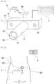
- Fig. 13 illustrates a state in which the patient at home adjusts the position of the chair-type phototherapy device 1 in alignment with the marking 23 given at hospital or clinic and performs light irradiation.
- a treatment site of the patient to be subjected to light irradiation is specified under a doctor's diagnosis at hospital or clinic.
- the sacral foramina where bladder sensory nerves exist is targeted and irradiated with light through the skin in order to suppress abnormal activities of sensory nerves in the bladder. Since appropriate treatment requires accurately targeting the sacral foramina the position of the sacral foramina to be irradiated with light in the patient back region 22 is specified, for example, by palpation or X-ray fluoroscopy.
- a doctor or other health professional puts a marking 23 on the specified treatment site.
- Ink or an adhesive sheet can be used as a material of the marking 23.
- the doctor specifies the sacral foramina at hospital and puts a marking 23 on the skin 35 immediately above to indicate the irradiation position and the irradiation range, and the patient refers to the marking 23 to appropriately arrange the radiation probe 9 (radiation probe front end portion 30) of the chair-type phototherapy device 1 at home to perform light irradiation.
- the patient performs light irradiation by himself/herself using the chair-type phototherapy device 1.
- the patient fixes the radiation module 3 of the chair-type phototherapy device 1 in alignment with the marking 23 given at hospital or clinic.
- the patient views an image captured by the observation module 10 on the monitor 7 to adjust the position of the radiation module 3 such that the marking 23 and the radiation probe 9 are fitted in a given position.
- the position between the radiation module 3 and the body is adjusted such that the cylinder of the radiation probe 9 is fitted in the hollow circular shape of the marking 23.
- the marking 23 is hidden under the radiation probe front end portion 30 when the radiation probe front end portion 30 comes into contact with the patient's skin 35, accurate position alignment is difficult, and, therefore, it is desirable that the marking 23 has such a shape that avoids the radiation probe front end portion 30.
- An example is a hollow circular shape having a radius larger than the radius of the radiation probe front end portion 30, although the embodiment is not limited thereto.
- the observation module 10 when the affected area is irradiated with light from the treatment light source 13, part of the irradiated light is reflected by the skin 35 and diffuses into the surrounding. If this reflected light is incident on the observation module 10, the observation module 10 causes halation to obscure the captured image.
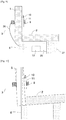
- Fig. 14 is a cross-sectional view as viewed from above (the patient's head side) in Fig. 13 , illustrating the radiation module 3 pressed against the skin 35.
- the radiation probe front end portion 30 when the radiation probe front end portion 30 is not in contact with the skin 35, light is not emitted from the treatment light source 13 as described above. Therefore, in the configuration in Fig.
- the radiation field 34 does not appear in the image captured by the observation module 10 but the outer edge of the radiation probe 9 and the marking 23 appear.
- the patient adjusts the position of the chair-type phototherapy device 1 such that the edge of the radiation probe 9 is matched with the marking 23.
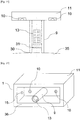
- the chair-type phototherapy device 1 according to a seventh embodiment of the present invention will be described with reference to Fig. 15 .
- the observation module 10 is directly influenced by variation in the quantity of external light, which may obscure an image. For example, when the surrounding illumination blinks on and off, an image of the observation module 10 flickers and is hard to see, making the position alignment operation difficult.
- a casing protrusion portion 36 having a shape surrounding the radiation probe 9 is provided on the outer peripheral side of the radiation probe 9 on a connection surface on which the treatment light source 13 and the radiation probe 9 are connected to the casing 11. Further, the front end of the casing protrusion portion 36 is positioned in flush with the radiation probe front end portion 30 or positioned slightly behind the radiation probe front end portion 30.
- the casing protrusion portion 36 is a cuboid in Fig. 15 , it may have, for example, a cylindrical shape.
- An observation illumination light source 15 for illuminating the skin 35 is provided in the inside of the casing protrusion portion 36.
- the illumination light source 15 is supplied with electricity from the not-illustrated power source 25 provided in the inside of the casing 11 and is turned on and off by a switch for the power source 25.
- the installation position of the illumination light source 15 is not limited to on the inner side of the casing protrusion portion 36, and the illumination light source 15 may be arranged on the connection surface of the casing 11 to which the observation module 10 and the radiation probe 9 are connected. Although the case of two illumination light sources 15 arranged is illustrated in Fig. 15 , one or two or more illumination light sources 15 may be installed.
- Fig. 16 is a cross-sectional view as viewed from above, illustrating the casing protrusion portion 36 and the radiation probe front end portion 30 pressed against the skin 35 in a positional relation in which the front end of the casing protrusion portion 36 is flush with the radiation probe front end portion 30.
- This configuration eliminates a gap between the skin 35 and the casing protrusion portion 36 under the condition of the radiation probe front end portion 30 being in contact with the skin 35, and therefore can prevent intrusion of external light into the observation module 10.
- external light does not enter the inside of the casing protrusion portion 36, an image of the inside of the casing protrusion portion 36 is unable to be obtained with the observation module 10.
- the marking 23 on the skin 35 and the radiation probe 9 therefore are illuminated by the illumination light source 15 provided in the inside of the casing protrusion portion 36.
- a clear image thus can be captured by the observation module 10 to enable the patient to perform position alignment operation of the chair-type phototherapy device 1 more easily and accurately, independently of surrounding brightness.
- light irradiation accurately targeted at the sacral foramina can be performed, and appropriate treatment can be achieved.
- the chair-type phototherapy device 1 has been described as a device for performing treatment of dysuria by irradiating the position of the sacral foramina of the patient with light rays.
- the present invention is not limited thereto and is applicable similarly to any phototherapy device as long as the light irradiation site is at a position that the patient is unable to see and the patient need to perform position alignment by himself/herself.
- the present invention is not limited to the foregoing embodiments and is susceptible to various modifications.
Landscapes
- Health & Medical Sciences (AREA)
- Life Sciences & Earth Sciences (AREA)
- Engineering & Computer Science (AREA)
- Biomedical Technology (AREA)
- General Health & Medical Sciences (AREA)
- Veterinary Medicine (AREA)
- Public Health (AREA)
- Animal Behavior & Ethology (AREA)
- Biophysics (AREA)
- Pathology (AREA)
- Physics & Mathematics (AREA)
- Heart & Thoracic Surgery (AREA)
- Medical Informatics (AREA)
- Molecular Biology (AREA)
- Surgery (AREA)
- Radiology & Medical Imaging (AREA)
- Nuclear Medicine, Radiotherapy & Molecular Imaging (AREA)
- Physical Education & Sports Medicine (AREA)
- Rehabilitation Therapy (AREA)
- Neurosurgery (AREA)
- Radiation-Therapy Devices (AREA)
Applications Claiming Priority (3)
| Application Number | Priority Date | Filing Date | Title |
|---|---|---|---|
| JP2018124653 | 2018-06-29 | ||
| JP2018184666 | 2018-09-28 | ||
| PCT/JP2019/025510 WO2020004516A1 (fr) | 2018-06-29 | 2019-06-27 | Dispositif de photothérapie de type chaise |
Publications (3)
| Publication Number | Publication Date |
|---|---|
| EP3815741A1 true EP3815741A1 (fr) | 2021-05-05 |
| EP3815741A4 EP3815741A4 (fr) | 2022-03-30 |
| EP3815741B1 EP3815741B1 (fr) | 2025-08-27 |
Family
ID=68984765
Family Applications (1)
| Application Number | Title | Priority Date | Filing Date |
|---|---|---|---|
| EP19825986.3A Active EP3815741B1 (fr) | 2018-06-29 | 2019-06-27 | Dispositif de photothérapie de type chaise |
Country Status (8)
| Country | Link |
|---|---|
| US (1) | US11571588B2 (fr) |
| EP (1) | EP3815741B1 (fr) |
| JP (1) | JP7032529B2 (fr) |
| KR (1) | KR102597733B1 (fr) |
| CN (1) | CN112312965B (fr) |
| CA (1) | CA3104033A1 (fr) |
| ES (1) | ES3042576T3 (fr) |
| WO (1) | WO2020004516A1 (fr) |
Families Citing this family (4)
| Publication number | Priority date | Publication date | Assignee | Title |
|---|---|---|---|---|
| WO2022019293A1 (fr) | 2020-07-21 | 2022-01-27 | 帝人ファーマ株式会社 | Appareil d'exposition à un faisceau de lumière |
| CA3203151A1 (fr) * | 2020-11-30 | 2022-06-02 | Teijin Pharma Limited | Appareil phototherapeutique |
| CN114028729B (zh) * | 2021-12-02 | 2023-10-20 | 固安翌光科技有限公司 | 一种光疗装置 |
| CN116898695A (zh) * | 2023-08-14 | 2023-10-20 | 福建乐摩物联科技有限公司 | 一种水流按摩椅 |
Family Cites Families (29)
| Publication number | Priority date | Publication date | Assignee | Title |
|---|---|---|---|---|
| JP2001520560A (ja) * | 1997-04-18 | 2001-10-30 | エキソゲン,インコーポレイティド | 超音波処理用浸水システム |
| JP2001238968A (ja) * | 2000-03-01 | 2001-09-04 | Ya Man Ltd | レーザ光照射プローブ |
| JP2003019217A (ja) | 2001-07-06 | 2003-01-21 | Tokyo Iken Kk | 光線治療器と、光線治療器等に使用される支持機構 |
| JP2003024458A (ja) * | 2002-06-27 | 2003-01-28 | Ya Man Ltd | レーザ光照射プローブ |
| JP2004141327A (ja) * | 2002-10-23 | 2004-05-20 | Ya Man Ltd | 美容処理装置 |
| JP3999134B2 (ja) * | 2003-01-24 | 2007-10-31 | アロカ株式会社 | 経直腸型超音波診断装置 |
| US20050203496A1 (en) * | 2004-03-12 | 2005-09-15 | Ritchie Paul G. | Medical apparatus and method useful for thermal treatment of a lumen |
| WO2006108093A2 (fr) * | 2005-04-06 | 2006-10-12 | Board Of Trustees Of Michigan State University | Systeme pour rayonnement laser de faible intensite |
| CN2790508Y (zh) * | 2005-04-18 | 2006-06-28 | 权贞子 | 远红外线温热仪 |
| US20070139930A1 (en) * | 2005-12-19 | 2007-06-21 | Paul Spivak | Method and system for led light therapy |
| US20080065175A1 (en) * | 2006-09-09 | 2008-03-13 | Redmond Russell J | Therapeutic radiation device |
| JP2009034240A (ja) | 2007-07-31 | 2009-02-19 | Panasonic Electric Works Co Ltd | 発毛調節光照射装置 |
| JP5284650B2 (ja) | 2008-01-22 | 2013-09-11 | 国立大学法人 千葉大学 | 排尿障害の改善及び/又は治療に使用するレーザーの用途 |
| US8907309B2 (en) * | 2009-04-17 | 2014-12-09 | Stephen L. Spotts | Treatment delivery control system and method of operation thereof |
| KR101125505B1 (ko) * | 2010-01-06 | 2012-03-21 | 단국대학교 산학협력단 | 차량용 탑승자 두피 광학 치료 장치 |
| JP2011212276A (ja) * | 2010-03-31 | 2011-10-27 | Katsunori Nonogaki | 超音波照射装置 |
| MX2013001146A (es) * | 2010-07-28 | 2013-04-29 | Ya Man Ltd | Dispositivo para alivio del dolor. |
| DE102010051162A1 (de) * | 2010-11-15 | 2012-05-16 | Lüllau Engineering Gmbh | Verfahren und Vorrichtung zum Bestrahlen unregelmäßig geformter Flächen |
| CN102626540A (zh) | 2011-02-22 | 2012-08-08 | 深圳市倍轻松科技股份有限公司 | 一种光子治疗控制系统及光子治疗椅 |
| CN201974619U (zh) | 2011-03-25 | 2011-09-14 | 江苏中准数据有限公司 | 接触式摄像模组 |
| JP6112532B2 (ja) | 2011-11-01 | 2017-04-12 | 澁谷工業株式会社 | レーザ治療器 |
| CN203874289U (zh) * | 2014-05-27 | 2014-10-15 | 赵全明 | 一种腰部微波理疗椅 |
| CN204798275U (zh) * | 2015-02-17 | 2015-11-25 | 滕新红 | 新型多功能针灸座椅 |
| CN204542759U (zh) * | 2015-03-28 | 2015-08-12 | 无锡市人民医院 | 一种辅助治疗腰椎病的腰椎保健椅 |
| CN205108757U (zh) | 2015-11-06 | 2016-03-30 | 谢晓龙 | 背式探头固定器和微波治疗仪 |
| CN205494134U (zh) | 2016-03-30 | 2016-08-24 | 彭小金 | 一种痔疮治疗装置 |
| CN209236201U (zh) | 2016-08-17 | 2019-08-13 | 北京万孛力医疗器械有限公司 | 尿失禁治疗设备 |
| WO2018090131A1 (fr) * | 2016-11-16 | 2018-05-24 | Klox Technologies Limited | Dispositifs, systèmes et procédés de photothérapie de sites de traitement |
| CN106621070B (zh) * | 2017-02-23 | 2018-12-11 | 合肥京东方光电科技有限公司 | 一种激光针灸系统及激光针灸设备 |
-
2019
- 2019-06-27 CA CA3104033A patent/CA3104033A1/fr active Pending
- 2019-06-27 WO PCT/JP2019/025510 patent/WO2020004516A1/fr not_active Ceased
- 2019-06-27 ES ES19825986T patent/ES3042576T3/es active Active
- 2019-06-27 EP EP19825986.3A patent/EP3815741B1/fr active Active
- 2019-06-27 JP JP2020527612A patent/JP7032529B2/ja active Active
- 2019-06-27 KR KR1020217000767A patent/KR102597733B1/ko active Active
- 2019-06-27 US US17/255,208 patent/US11571588B2/en active Active
- 2019-06-27 CN CN201980044058.7A patent/CN112312965B/zh active Active
Also Published As
| Publication number | Publication date |
|---|---|
| CA3104033A1 (fr) | 2020-01-02 |
| US11571588B2 (en) | 2023-02-07 |
| EP3815741B1 (fr) | 2025-08-27 |
| CN112312965B (zh) | 2023-05-09 |
| EP3815741A4 (fr) | 2022-03-30 |
| KR20210018492A (ko) | 2021-02-17 |
| WO2020004516A1 (fr) | 2020-01-02 |
| CN112312965A (zh) | 2021-02-02 |
| US20210268308A1 (en) | 2021-09-02 |
| ES3042576T3 (en) | 2025-11-21 |
| KR102597733B1 (ko) | 2023-11-02 |
| JP7032529B2 (ja) | 2022-03-08 |
| JPWO2020004516A1 (ja) | 2021-04-22 |
Similar Documents
| Publication | Publication Date | Title |
|---|---|---|
| EP3815741B1 (fr) | Dispositif de photothérapie de type chaise | |
| EP3205373B1 (fr) | Système de stimulation magnétique transcrânienne | |
| EP3636317B1 (fr) | Appareil photothérapeutique | |
| US20090080186A1 (en) | Medical examination apparatus | |
| CN106999141B (zh) | 乳房计算机断层摄影系统 | |
| US20140050298A1 (en) | Intra-oral x-ray imaging device equipped with camera | |
| US20180279945A1 (en) | Vein visualization device | |
| US20170291037A1 (en) | Transcranial magnetic stimulation system | |
| KR20130057443A (ko) | 병변 영상 분석을 통한 광 치료 장치 및 이에 이용되는 핸드피스 | |
| KR20170046377A (ko) | 비침습 레이저 통증 완화장치 | |
| KR101734928B1 (ko) | 고주파 온열암치료기 | |
| JP2002360543A (ja) | 呼吸位相における同期点決定方法、及びそのために用いる呼吸位相モニタ装置 | |
| KR102495638B1 (ko) | 레이저 조사 장치 | |
| KR101192461B1 (ko) | 엑스선을 구강 외부에서 검출하는 구강 내 엑스선 촬영장치 | |
| US20210008386A1 (en) | Systems and Methods for the Automated Delivery of Photobiomodulation Therapy to a Patient | |
| KR20230053061A (ko) | 객체인식을 활용한 장치 및 방법 | |
| CN221815163U (zh) | 一种康复激光治疗仪 | |
| KR102107593B1 (ko) | 씨암용 엑스선 표시장치 및 이를 포함하는 씨암 | |
| WO2025097469A1 (fr) | Dispositif de thérapie laser pour rééducation | |
| JP2024091607A (ja) | 照射システム | |
| CN115920249A (zh) | 一种中红外光理疗机 | |
| RU151662U1 (ru) | Лазерный физиотерапевтический аппарат | |
| KR20110131453A (ko) | 피부암 진단 및 치료장치 |
Legal Events
| Date | Code | Title | Description |
|---|---|---|---|
| STAA | Information on the status of an ep patent application or granted ep patent |
Free format text: STATUS: THE INTERNATIONAL PUBLICATION HAS BEEN MADE |
|
| PUAI | Public reference made under article 153(3) epc to a published international application that has entered the european phase |
Free format text: ORIGINAL CODE: 0009012 |
|
| STAA | Information on the status of an ep patent application or granted ep patent |
Free format text: STATUS: REQUEST FOR EXAMINATION WAS MADE |
|
| 17P | Request for examination filed |
Effective date: 20201203 |
|
| AK | Designated contracting states |
Kind code of ref document: A1 Designated state(s): AL AT BE BG CH CY CZ DE DK EE ES FI FR GB GR HR HU IE IS IT LI LT LU LV MC MK MT NL NO PL PT RO RS SE SI SK SM TR |
|
| DAV | Request for validation of the european patent (deleted) | ||
| DAX | Request for extension of the european patent (deleted) | ||
| A4 | Supplementary search report drawn up and despatched |
Effective date: 20220228 |
|
| RIC1 | Information provided on ipc code assigned before grant |
Ipc: A61N 5/01 20060101ALI20220222BHEP Ipc: A61N 5/067 20060101ALI20220222BHEP Ipc: A61N 5/06 20060101AFI20220222BHEP |
|
| GRAP | Despatch of communication of intention to grant a patent |
Free format text: ORIGINAL CODE: EPIDOSNIGR1 |
|
| STAA | Information on the status of an ep patent application or granted ep patent |
Free format text: STATUS: GRANT OF PATENT IS INTENDED |
|
| RIC1 | Information provided on ipc code assigned before grant |
Ipc: A61B 5/00 20060101ALI20250321BHEP Ipc: A61N 5/01 20060101ALI20250321BHEP Ipc: A61N 5/067 20060101ALI20250321BHEP Ipc: A61N 5/06 20060101AFI20250321BHEP |
|
| INTG | Intention to grant announced |
Effective date: 20250415 |
|
| GRAS | Grant fee paid |
Free format text: ORIGINAL CODE: EPIDOSNIGR3 |
|
| GRAA | (expected) grant |
Free format text: ORIGINAL CODE: 0009210 |
|
| STAA | Information on the status of an ep patent application or granted ep patent |
Free format text: STATUS: THE PATENT HAS BEEN GRANTED |
|
| AK | Designated contracting states |
Kind code of ref document: B1 Designated state(s): AL AT BE BG CH CY CZ DE DK EE ES FI FR GB GR HR HU IE IS IT LI LT LU LV MC MK MT NL NO PL PT RO RS SE SI SK SM TR |
|
| REG | Reference to a national code |
Ref country code: GB Ref legal event code: FG4D |
|
| REG | Reference to a national code |
Ref country code: CH Ref legal event code: EP |
|
| REG | Reference to a national code |
Ref country code: DE Ref legal event code: R096 Ref document number: 602019074851 Country of ref document: DE |
|
| REG | Reference to a national code |
Ref country code: IE Ref legal event code: FG4D |
|
| REG | Reference to a national code |
Ref country code: NL Ref legal event code: FP |
|
| REG | Reference to a national code |
Ref country code: ES Ref legal event code: FG2A Ref document number: 3042576 Country of ref document: ES Kind code of ref document: T3 Effective date: 20251121 |
|
| PG25 | Lapsed in a contracting state [announced via postgrant information from national office to epo] |
Ref country code: IS Free format text: LAPSE BECAUSE OF FAILURE TO SUBMIT A TRANSLATION OF THE DESCRIPTION OR TO PAY THE FEE WITHIN THE PRESCRIBED TIME-LIMIT Effective date: 20251227 |
|
| PG25 | Lapsed in a contracting state [announced via postgrant information from national office to epo] |
Ref country code: NO Free format text: LAPSE BECAUSE OF FAILURE TO SUBMIT A TRANSLATION OF THE DESCRIPTION OR TO PAY THE FEE WITHIN THE PRESCRIBED TIME-LIMIT Effective date: 20251127 |
|
| REG | Reference to a national code |
Ref country code: LT Ref legal event code: MG9D |
|
| PG25 | Lapsed in a contracting state [announced via postgrant information from national office to epo] |
Ref country code: PT Free format text: LAPSE BECAUSE OF FAILURE TO SUBMIT A TRANSLATION OF THE DESCRIPTION OR TO PAY THE FEE WITHIN THE PRESCRIBED TIME-LIMIT Effective date: 20251229 |
|
| PG25 | Lapsed in a contracting state [announced via postgrant information from national office to epo] |
Ref country code: FI Free format text: LAPSE BECAUSE OF FAILURE TO SUBMIT A TRANSLATION OF THE DESCRIPTION OR TO PAY THE FEE WITHIN THE PRESCRIBED TIME-LIMIT Effective date: 20250827 |
|
| PG25 | Lapsed in a contracting state [announced via postgrant information from national office to epo] |
Ref country code: HR Free format text: LAPSE BECAUSE OF FAILURE TO SUBMIT A TRANSLATION OF THE DESCRIPTION OR TO PAY THE FEE WITHIN THE PRESCRIBED TIME-LIMIT Effective date: 20250827 |
|
| PG25 | Lapsed in a contracting state [announced via postgrant information from national office to epo] |
Ref country code: GR Free format text: LAPSE BECAUSE OF FAILURE TO SUBMIT A TRANSLATION OF THE DESCRIPTION OR TO PAY THE FEE WITHIN THE PRESCRIBED TIME-LIMIT Effective date: 20251128 |
|
| PG25 | Lapsed in a contracting state [announced via postgrant information from national office to epo] |
Ref country code: SE Free format text: LAPSE BECAUSE OF FAILURE TO SUBMIT A TRANSLATION OF THE DESCRIPTION OR TO PAY THE FEE WITHIN THE PRESCRIBED TIME-LIMIT Effective date: 20250827 |
|
| PG25 | Lapsed in a contracting state [announced via postgrant information from national office to epo] |
Ref country code: LV Free format text: LAPSE BECAUSE OF FAILURE TO SUBMIT A TRANSLATION OF THE DESCRIPTION OR TO PAY THE FEE WITHIN THE PRESCRIBED TIME-LIMIT Effective date: 20250827 |
|
| PG25 | Lapsed in a contracting state [announced via postgrant information from national office to epo] |
Ref country code: BG Free format text: LAPSE BECAUSE OF FAILURE TO SUBMIT A TRANSLATION OF THE DESCRIPTION OR TO PAY THE FEE WITHIN THE PRESCRIBED TIME-LIMIT Effective date: 20250827 Ref country code: PL Free format text: LAPSE BECAUSE OF FAILURE TO SUBMIT A TRANSLATION OF THE DESCRIPTION OR TO PAY THE FEE WITHIN THE PRESCRIBED TIME-LIMIT Effective date: 20250827 |
|
| PG25 | Lapsed in a contracting state [announced via postgrant information from national office to epo] |
Ref country code: RS Free format text: LAPSE BECAUSE OF FAILURE TO SUBMIT A TRANSLATION OF THE DESCRIPTION OR TO PAY THE FEE WITHIN THE PRESCRIBED TIME-LIMIT Effective date: 20251127 |
|
| REG | Reference to a national code |
Ref country code: AT Ref legal event code: MK05 Ref document number: 1829339 Country of ref document: AT Kind code of ref document: T Effective date: 20250827 |
|
| PG25 | Lapsed in a contracting state [announced via postgrant information from national office to epo] |
Ref country code: SM Free format text: LAPSE BECAUSE OF FAILURE TO SUBMIT A TRANSLATION OF THE DESCRIPTION OR TO PAY THE FEE WITHIN THE PRESCRIBED TIME-LIMIT Effective date: 20250827 |
|
| PG25 | Lapsed in a contracting state [announced via postgrant information from national office to epo] |
Ref country code: DK Free format text: LAPSE BECAUSE OF FAILURE TO SUBMIT A TRANSLATION OF THE DESCRIPTION OR TO PAY THE FEE WITHIN THE PRESCRIBED TIME-LIMIT Effective date: 20250827 |
|
| PG25 | Lapsed in a contracting state [announced via postgrant information from national office to epo] |
Ref country code: AT Free format text: LAPSE BECAUSE OF FAILURE TO SUBMIT A TRANSLATION OF THE DESCRIPTION OR TO PAY THE FEE WITHIN THE PRESCRIBED TIME-LIMIT Effective date: 20250827 |
|
| PG25 | Lapsed in a contracting state [announced via postgrant information from national office to epo] |
Ref country code: CZ Free format text: LAPSE BECAUSE OF FAILURE TO SUBMIT A TRANSLATION OF THE DESCRIPTION OR TO PAY THE FEE WITHIN THE PRESCRIBED TIME-LIMIT Effective date: 20250827 |
|
| PG25 | Lapsed in a contracting state [announced via postgrant information from national office to epo] |
Ref country code: SK Free format text: LAPSE BECAUSE OF FAILURE TO SUBMIT A TRANSLATION OF THE DESCRIPTION OR TO PAY THE FEE WITHIN THE PRESCRIBED TIME-LIMIT Effective date: 20250827 Ref country code: EE Free format text: LAPSE BECAUSE OF FAILURE TO SUBMIT A TRANSLATION OF THE DESCRIPTION OR TO PAY THE FEE WITHIN THE PRESCRIBED TIME-LIMIT Effective date: 20250827 |