EP3815792A1 - Pompe à mousse - Google Patents
Pompe à mousse Download PDFInfo
- Publication number
- EP3815792A1 EP3815792A1 EP19206040.8A EP19206040A EP3815792A1 EP 3815792 A1 EP3815792 A1 EP 3815792A1 EP 19206040 A EP19206040 A EP 19206040A EP 3815792 A1 EP3815792 A1 EP 3815792A1
- Authority
- EP
- European Patent Office
- Prior art keywords
- valve
- pump
- chamber
- foam
- section
- Prior art date
- Legal status (The legal status is an assumption and is not a legal conclusion. Google has not performed a legal analysis and makes no representation as to the accuracy of the status listed.)
- Granted
Links
Images


Classifications
-
- B—PERFORMING OPERATIONS; TRANSPORTING
- B05—SPRAYING OR ATOMISING IN GENERAL; APPLYING FLUENT MATERIALS TO SURFACES, IN GENERAL
- B05B—SPRAYING APPARATUS; ATOMISING APPARATUS; NOZZLES
- B05B11/00—Single-unit hand-held apparatus in which flow of contents is produced by the muscular force of the operator at the moment of use
- B05B11/0005—Components or details
- B05B11/0062—Outlet valves actuated by the pressure of the fluid to be sprayed
- B05B11/007—Outlet valves actuated by the pressure of the fluid to be sprayed being opened by deformation of a sealing element made of resiliently deformable material, e.g. flaps, skirts, duck-bill valves
-
- A—HUMAN NECESSITIES
- A47—FURNITURE; DOMESTIC ARTICLES OR APPLIANCES; COFFEE MILLS; SPICE MILLS; SUCTION CLEANERS IN GENERAL
- A47K—SANITARY EQUIPMENT; ACCESSORIES THEREFOR, e.g. TOILET ACCESSORIES
- A47K5/00—Holders or dispensers for soap, toothpaste or the like
- A47K5/14—Foam or lather making devices
-
- B—PERFORMING OPERATIONS; TRANSPORTING
- B05—SPRAYING OR ATOMISING IN GENERAL; APPLYING FLUENT MATERIALS TO SURFACES, IN GENERAL
- B05B—SPRAYING APPARATUS; ATOMISING APPARATUS; NOZZLES
- B05B11/00—Single-unit hand-held apparatus in which flow of contents is produced by the muscular force of the operator at the moment of use
- B05B11/01—Single-unit hand-held apparatus in which flow of contents is produced by the muscular force of the operator at the moment of use characterised by the means producing the flow
- B05B11/10—Pump arrangements for transferring the contents from the container to a pump chamber by a sucking effect and forcing the contents out through the dispensing nozzle
- B05B11/1001—Piston pumps
- B05B11/1004—Piston pumps comprising a movable cylinder and a stationary piston
-
- B—PERFORMING OPERATIONS; TRANSPORTING
- B05—SPRAYING OR ATOMISING IN GENERAL; APPLYING FLUENT MATERIALS TO SURFACES, IN GENERAL
- B05B—SPRAYING APPARATUS; ATOMISING APPARATUS; NOZZLES
- B05B11/00—Single-unit hand-held apparatus in which flow of contents is produced by the muscular force of the operator at the moment of use
- B05B11/01—Single-unit hand-held apparatus in which flow of contents is produced by the muscular force of the operator at the moment of use characterised by the means producing the flow
- B05B11/10—Pump arrangements for transferring the contents from the container to a pump chamber by a sucking effect and forcing the contents out through the dispensing nozzle
- B05B11/1087—Combination of liquid and air pumps
-
- B—PERFORMING OPERATIONS; TRANSPORTING
- B05—SPRAYING OR ATOMISING IN GENERAL; APPLYING FLUENT MATERIALS TO SURFACES, IN GENERAL
- B05B—SPRAYING APPARATUS; ATOMISING APPARATUS; NOZZLES
- B05B11/00—Single-unit hand-held apparatus in which flow of contents is produced by the muscular force of the operator at the moment of use
- B05B11/0005—Components or details
- B05B11/0027—Means for neutralising the actuation of the sprayer ; Means for preventing access to the sprayer actuation means
- B05B11/0032—Manually actuated means located downstream the discharge nozzle for closing or covering it, e.g. shutters
-
- B—PERFORMING OPERATIONS; TRANSPORTING
- B05—SPRAYING OR ATOMISING IN GENERAL; APPLYING FLUENT MATERIALS TO SURFACES, IN GENERAL
- B05B—SPRAYING APPARATUS; ATOMISING APPARATUS; NOZZLES
- B05B7/00—Spraying apparatus for discharge of liquids or other fluent materials from two or more sources, e.g. of liquid and air, of powder and gas
- B05B7/0018—Spraying apparatus for discharge of liquids or other fluent materials from two or more sources, e.g. of liquid and air, of powder and gas with devices for making foam
- B05B7/0025—Spraying apparatus for discharge of liquids or other fluent materials from two or more sources, e.g. of liquid and air, of powder and gas with devices for making foam with a compressed gas supply
- B05B7/0031—Spraying apparatus for discharge of liquids or other fluent materials from two or more sources, e.g. of liquid and air, of powder and gas with devices for making foam with a compressed gas supply with disturbing means promoting mixing, e.g. balls, crowns
- B05B7/0037—Spraying apparatus for discharge of liquids or other fluent materials from two or more sources, e.g. of liquid and air, of powder and gas with devices for making foam with a compressed gas supply with disturbing means promoting mixing, e.g. balls, crowns including sieves, porous members or the like
-
- B—PERFORMING OPERATIONS; TRANSPORTING
- B05—SPRAYING OR ATOMISING IN GENERAL; APPLYING FLUENT MATERIALS TO SURFACES, IN GENERAL
- B05B—SPRAYING APPARATUS; ATOMISING APPARATUS; NOZZLES
- B05B7/00—Spraying apparatus for discharge of liquids or other fluent materials from two or more sources, e.g. of liquid and air, of powder and gas
- B05B7/0018—Spraying apparatus for discharge of liquids or other fluent materials from two or more sources, e.g. of liquid and air, of powder and gas with devices for making foam
- B05B7/0025—Spraying apparatus for discharge of liquids or other fluent materials from two or more sources, e.g. of liquid and air, of powder and gas with devices for making foam with a compressed gas supply
- B05B7/0031—Spraying apparatus for discharge of liquids or other fluent materials from two or more sources, e.g. of liquid and air, of powder and gas with devices for making foam with a compressed gas supply with disturbing means promoting mixing, e.g. balls, crowns
- B05B7/0043—Spraying apparatus for discharge of liquids or other fluent materials from two or more sources, e.g. of liquid and air, of powder and gas with devices for making foam with a compressed gas supply with disturbing means promoting mixing, e.g. balls, crowns including a plurality of individual elements, e.g. needles, baffles, rotatable blades
Definitions
- the invention relates to a foam pump for arrangement on a container filled with liquid with the features of the preamble of claim 1.
- foam pumps are known from the prior art and are used to produce a foam from a foamable liquid medium, for example a liquid soap or a foamable disinfectant solution, by mixing with air, which when the foam pump is operated, for example, in a user's hand can be output.
- Foam pumps are known which can take liquid from a flexible container, for example from a bag.
- foam pumps are known which can suck liquid from a dimensionally stable container and thus evacuate it.
- a non-evacuating foam pump is for example from the document EP 2 127 756 A1 known.
- the foam pump has a mixing chamber into which air can be introduced through a beak valve when actuated from a pump bellows. After a pumping process, the liquid flows out of the container again into the mixing chamber from a container arranged above the mixing chamber due to gravity.
- Evacuating foam pumps are mostly designed for either dispensing foam soap or dispensing foam disinfectant.
- Universally applicable foam pumps which can pump or suck both foam soap and foam disinfectant, have a complex structure and they contain components that do not allow simple disposal.
- metal springs or glass balls are used as tensioning elements and check valves in such foam pumps.
- a generic foam pump for arrangement on a container filled with liquid comprises a valve carrier in which an inlet valve is received, as well as a valve tube which is received in the valve carrier so as to be movable in a stroke while changing a volume in a pumping chamber.
- the foam pump also has a pump bellows with an air chamber, from which air can flow over into a mixing chamber when the valve tube is lifted. The air is mixed with the liquid in the mixing chamber.
- Foam sieves for foaming the liquid are arranged downstream.
- the known foam pump cannot be used universally and is expensive and complex to assemble.
- the foam quality of the foam pump is essentially satisfactory for only one type of liquid.
- the foam pump has a large number of individual parts to be assembled with one another.
- the object of the invention to develop a foam pump in such a way that it is easy to dispose of without the need for complex dismantling.
- the foam pump should be able to be used for different types of foamable liquids, for example for foam soap and for a foam disinfectant solution, in particular the foam pump should be able to evacuate a container for providing the liquid.
- the invention provides that a beak valve is arranged between the pump chamber and the mixing chamber, through which liquid can flow over from the pump chamber into the mixing chamber during a stroke movement of the valve tube relative to the valve carrier, and that between the air chamber and a flutter valve is arranged in the mixing chamber, by means of which air from the air chamber in the pump bellows can flow over into the mixing chamber during a stroke movement of the valve tube relative to the valve carrier.
- the term “between” does not necessarily mean “spatially between”. I. E. the beak valve does not have to be arranged spatially directly between the pumping chamber and the mixing chamber. Rather, the term “between” means that the duckbill valve is arranged with regard to the fluidic connection between the pumping chamber and the mixing chamber. This applies accordingly to the flutter valve and its arrangement between the air chamber and the mixing chamber.
- the core idea of the invention is an advantageous valve combination of a beak valve and a flutter valve, whereby liquid can get from the pumping chamber into the mixing chamber via the beak valve, but which blocks the passage of liquid from the mixing chamber back into the pumping chamber.
- the flutter valve forms a valve for a gaseous medium in a simple manner.
- the flutter valve and the beak valve are designed and arranged according to the invention in such a way that they are moved into their open position in the course of a lifting movement with which the volume of the pump chamber is reduced and at the same time the volume of the air chamber is also reduced.
- liquid can be conveyed from the pump chamber and from there into the mixing chamber and, on the other hand, air can be conveyed from the air chamber into the mixing chamber.
- air can be conveyed from the air chamber into the mixing chamber.
- a foam pump of simple design which, through the variability of the volume of the pump chamber in connection with the inlet valve, can evacuate a container for providing the liquid to be foamed.
- the good sealing effect that can be achieved with the foam pump according to the invention is not only important for the evacuating effect. Rather, the good sealing effect also ensures that the liquid and the foam can only flow in the conveying direction, but not in the opposite direction. In particular, it is also possible to effectively prevent impurities from getting into the foam pump or the container from the outside, which otherwise could even lead to contamination in the worst case.
- the foam pump according to the invention is characterized in that, due to the similarly selectable materials for the components of the foam pump from the field of plastics, the foam pump can be disposed of without material separations.
- the beak valve and / or the flutter valve is advantageously accommodated in the valve tube, with which a compact structure can be realized.
- the desired valve action of the flutter valve can be achieved in a simple manner if the flutter valve is arranged in contact with the inside of the wall of the valve tube.
- the flutter valve is fully attached to the z. B. is designed as a cylinder jacket inner wall of the valve tube.
- the flutter valve does not or at least not completely cover the openings.
- the sealing effect of the flutter valve can in this case be achieved in that in its closed position it lies against the inner wall in a sealing manner and thus separates the air chamber from the mixing chamber.
- the beak valve and the flutter valve are designed as a combination valve with a unitary and one-piece base body. In this way, a particularly simple structure can be implemented with little assembly effort.
- the combination valve can be used with the base body in the valve tube.
- the base body of the combination valve is preferably designed in such a way that it has a base section and a screen section, the screen section being formed on the outer circumference of the base section and projecting over it all the way round.
- the flutter valve can be formed by the umbrella section, while the beak valve is formed in the area of the base section.
- one or more openings can be present in the wall of the valve tube at the level of the umbrella section resting on the inside, which are covered by the umbrella section in the closed position of the flutter valve and / or whose fluidic connection with the mixing chamber is closed by the umbrella section.
- the pump bellows is compressed by actuating the foam pump, the pressure in the air chamber of the pump bellows rises above the pressure in the mixing chamber.
- the screen section lifts at least briefly from the inner wall, so that air from the air chamber through the opening into the z. B. reaches the mixing chamber formed within the valve tube. If the pressure difference is undershot again, the screen section deforms back and rests against the inner wall again, i. H.
- the flutter valve is closed again. As a result, a backflow of air from the mixing chamber back into the air chamber of the pump bellows with the flutter valve thus formed is prevented.
- the flutter valve can also be referred to as a lamella valve.
- the combination valve is preferably designed in such a way that the umbrella section is shaped like a collar or funnel in the non-installed state and roofs over or encloses the base section - at least in the non-installed state.
- the base section is preferably enclosed approximately in the manner of an umbrella and, if necessary, with a corresponding distance between the shield section and the base section.
- the screen section form a downwardly inclined collar in the direction of the free end of the base section. It can thus be achieved that - when the combination valve is installed - the screen section is stretched upwards in a certain way away from the base section, so that the screen section is inverted from the non-installed state to the installed state along a central axis by a predetermined angle.
- the shield section rests against the inner wall of the valve tube with a predetermined pretension.
- This bias in a certain way dictates the pressure difference that must be exceeded in order to move the flutter valve into its open position.
- the combination valve can be designed in such a way that when it is installed the umbrella section is turned inside out by an angle of more than 20 ° and in particular more than 90 ° along the central axis. This results in a particularly secure contact of the shield section against the inside of the valve tube, so that there is a particularly good valve effect of the shield section with respect to the opening in the wall of the valve tube. However, it is also sufficient if the screen section is turned inside out at a smaller angle in order to achieve a good valve effect.
- a fluid channel can be provided which extends in particular along the central axis and opens into the beak valve of the combination valve. In the open position of the bill valve, the liquid can flow from the pumping chamber into the mixing chamber through this fluid channel.
- Another advantage is the combination valve or at least its base body made of a plastic, for. B. silicone, formed.
- the combination valve can thus be produced in a simple and cost-effective manner, with a good valve effect being achieved at the same time.
- silicone in particular is characterized by a high level of media resistance.
- the mixing chamber can be formed directly in the valve tube.
- the pump chamber can be formed in the valve tube.
- the valve carrier can have a piston section which extends into the valve tube, so that the piston section changes the volume in the pump chamber when the valve tube moves in a reciprocating manner.
- the piston section can be designed individually or the piston section forms a section of the valve carrier, which in particular can be made in one piece and made of the same material with the valve carrier.
- the piston section can be designed in the shape of a cylinder and its outer circumferential surface can be in sealing contact with the inside of the valve tube.
- the valve tube In order to guide a stroke movement of the valve tube relative to the valve carrier, the valve tube can be guided in a liquid-tight manner with an end-side section on the outer circumferential surface of the piston section, the liquid being able to perform a lubricating effect between the outer circumferential surface of the piston section and the inside of the valve tube.
- the inlet valve is particularly advantageously arranged on the valve carrier and, in particular, also in the piston section.
- the inlet valve is arranged on the head side in the piston section and has a valve disk which covers an overflow opening in the piston section. If the valve tube is returned to its starting position relative to the valve carrier after the foam pump has been actuated, the volume of the pump chamber increases, as a result of which liquid is drawn into the pump chamber via the inlet valve. For this, z. B. the valve disk from the overflow opening, whereby liquid can flow from the container into the pump chamber.
- the return of the valve tube to its starting position relative to the valve carrier can be done by the elastic action of the pump bellows and / or by external spring means, which, for. B. can be present in a receiving device of the foam pump.
- the combination valve is preferably accommodated in the valve tube itself and it can be moved along with the lifting movement of the valve tube.
- the valve tube can have an inwardly facing receiving collar on which the combination valve is received and which separates the pumping chamber from the mixing chamber within the valve tube.
- the pump bellows has a connecting piece which encloses a section of the valve tube on the outside, with at least one air inlet channel being formed in this area, through which air can flow into the air chamber of the pump bellows.
- the foam pump can be operated by means of an operating unit.
- This can have an actuating plate which can be actuated directly manually or indirectly through manual activation of a further external component in a receiving device for the container with the foam pump, whereby a respective pumping cycle is triggered.
- the actuation unit can have a sleeve-like section with which a movement of the actuation unit is guided along the valve tube and / or the connection piece of the pump bellows.
- the sleeve-like shaped section can be inserted into the valve tube in such a way that the actuating unit can be moved by a predetermined distance relative to the valve tube.
- the air-liquid mixture can pass through a fluid channel of the actuating unit from the mixing chamber to an output end.
- the actuation unit In order to trigger the pumping cycle, the actuation unit is coupled to the pump bellows in such a way that the pump bellows is compressed when the actuation unit is actuated. If the pump bellows relaxes again and is returned to its starting position (by elastic restoring forces or spring forces from external spring means), the actuating unit is also returned to its inoperative position.
- the actuation unit can be anchored to the socket of the pump bellows for this purpose, the actuation unit by means of a paragraph which, for. B. can be formed by the actuating plate, pushes the pump bellows into its compressed position.
- a part of the path that is covered can serve to close an air inlet opening formed between the connecting piece and the shoulder or actuating plate, through which air can flow from the outside into the air chamber of the pump bellows.
- At least one foam generator can be connected to the mixing chamber, which foam generator has at least two, three, four or more than four foam sieves.
- the foam generator with the several foam sieves can be arranged in an output end of the valve tube adjoining the mixing chamber or in the area of the actuation unit. If the liquid is premixed with the air in the mixing chamber and pressed through the foam sieves, for example micrometer mesh sieves, the sieves, especially in their spaced-apart arrangement one behind the other, produce a very dimensionally stable foam, which is particularly favored by the multiple foam sieves arranged one behind the other with formed in between Spaces. The result is a particularly dimensionally stable foam, in particular regardless of the type of liquid that is fed into the foam pump.
- Figure 1 shows an exemplary embodiment of a foam pump 1 according to the invention in a cross-sectional view.
- the foam pump 1 has a valve support 10.
- the valve carrier can, for. B. be made as an injection molded plastic component.
- the valve carrier 10 is designed so that it is attached to an in Figure 1 Not shown container, in which there is a liquid such as a foam soap or a foamable disinfectant solution, can be arranged.
- valve carrier 10 and thus also the foam pump 1 is designed so that the connection to the container is made by means of a screw connection.
- the valve carrier 10 has an internal thread 38, via which the foam pump 1 z. B. can be screwed to an output port of the container.
- the internal thread 38 In the area enclosed by the internal thread 38 there are feed lines to a valve system to which the soap or the solution can flow.
- the internal thread of the valve support 10 can be tightly sealed with a headwind formed on the container.
- the sealing effect is achieved by a sealing cone 43 which is formed on the valve carrier 10 and which can bear against a neck of the container in a sealing manner.
- the valve carrier 10 Around its central center axis 25, the valve carrier 10 has a piston section 27 which forms a rigid section of the valve carrier 10 within the internal thread 38.
- the piston section 27 has a flat end face with an overflow opening 36 through which liquid can pass from the container into an adjoining pump chamber 14.
- the pump chamber 14 is formed by a valve tube 12.
- the valve tube 12 is pushed onto a cylindrical outer circumferential surface of the piston section 27 and is guided axially movably along the central axis 25 on the piston section 27. If the valve tube 12 is moved axially up and down in the direction of the central axis 25, one end section of the valve tube 12 slides over the piston section 27 to a different extent, which leads to a change in the volume of the pump chamber 13. If the valve tube 12 is pushed further onto the piston section 27 by actuation of the foam pump 1, the volume of the pump chamber 13 is reduced Pump chamber 13 increases in size. An increase in the volume of the pump chamber 13 causes a negative pressure in the Pump chamber 13 opposite the container, whereby the inlet valve 11 is moved into its open position and liquid can flow from the container through the overflow opening 36 into the pump chamber 13.
- a mixing chamber 16 which is separated from the pump chamber 13 by a combination valve 17 inserted in the valve tube 12.
- the combination valve 17 is firmly received within the valve tube 12 via a receiving collar 28.
- the combination valve 17 has a base body 18 with a base section 19 and an adjoining umbrella section 20.
- a fluid channel 26, which opens into a beak valve 21, extends centrally through the base section 19.
- the shield section 20 of the combination valve rests against an inner wall of the valve tube 12 and covers openings 22 which are provided in this area in the wall 23 of the valve tube 12.
- valve tube 12 If the valve tube 12 is moved in the direction of the piston section 27 by actuation of the foam pump 1, the volume of the pump chamber 13 is reduced the container can flow into the pump chamber 13. On the other hand, the overpressure generated in the pump chamber 13 moves the ducted valve 21 into its open position, so that liquid can flow through the fluid channel 26 and the ducted valve 21 into the mixing chamber 16.
- the foam pump 1 also has a pump bellows 15.
- the pump bellows 15 has on its one end face a receiving collar for connection to the valve carrier 10. On its other end face it has a connecting piece 33 by means of which the pump bellows 15 is connected to the valve tube 12. In between, the pump bellows 15 forms an air chamber 14. This is delimited on its outer circumference by several cylinder-like bellows sections with gradually decreasing diameters. This is delimited on its inner circumference by the wall 23 of the valve tube 12.
- the air chamber 14 of the pump bellows 15 is fluidically connected to the mixing chamber 16 formed in the valve tube 12 via the openings 22 in the wall 23 of the valve tube 12, which are provided in the area of the mixing chamber 26 and covered by the umbrella section 20 of the combination valve.
- the umbrella section 20 forms a flutter valve via which air can selectively flow over from the air chamber 14 into the mixing chamber 16.
- the mode of operation is as follows: If the foam pump 1 is actuated, liquid flows - as already explained above - through the beak valve 21 into the mixing chamber 16. At the same time, the pump bellows 15 is compressed, whereby the volume of the air chamber 14 is reduced and the air pressure in the air chamber 14 rises. If the pressure in the air chamber 14 exceeds the pressure in the mixing chamber 16, the screen section 20 lifts off in some areas from the inside of the wall 23 of the valve tube 12 so that air can flow through the openings 22 into the mixing chamber 16. In this way, air can be mixed with the liquid from the pump chamber 13, which air is premixed in the mixing chamber 16 and, if necessary, also prefoamed.
- the two foam generators 30 are designed as sleeve bodies and have flat foam sieves 31 on the flat side, so that when the foam generators 30 are spaced apart from one another, a total of four foam sieves 31 follow the foam channel after the mixing chamber 16 in order to dispense the finest possible foam from the liquid-air mixture produce.
- the foam sieves 31 preferably form micrometer sieves, e.g. B. with a mesh size in the range of 100 microns.
- the swirl unit 32 and the two foam generators 30 are each arranged in a sleeve-like section of an actuation unit 41.
- the actuation unit 41 has an actuation plate 37 via which the foam pump 1 can be actuated.
- the foam pump 1 can, for example, be inserted into a corresponding device, the actuating plate 37 being moved up and down by manual activation of a further external component in the receiving device, thereby triggering a respective pumping cycle.
- the volume in the pumping chamber 13 then decreases and increases again due to the return movement of the valve tube 12 due to the elastic reshaping of the pump bellows 15 or due to the spring forces of external spring means.
- the inlet valve 11 When the volume in the pumping chamber 13 increases, the inlet valve 11 is moved into its open position as a result of the negative pressure prevailing therein. I. E. the valve disk 36 lifts off the overflow opening 36 and liquid can be drawn into the pump chamber 13 through the overflow opening 36. At the same time, the beak valve 21 of the combination valve 17 closes. it is prevented that liquid or an air-liquid mixture is sucked out of the mixing chamber 16 into the pump chamber 13. In addition, during this movement the flutter valve 24 closes due to the negative pressure prevailing in the pump bellows 15, which prevents liquid or an air-liquid mixture from being sucked out of the mixing chamber 16 into the air chamber 14. Due to the negative pressure in the air chamber 14, however, air is sucked from the area below the actuation plate 37 into the air chamber 14 of the pump bellows 15 through the air inlet duct 34 which is then opened.
- the foam pump 1 is actuated again, the volume of the pump chamber 13 is reduced again and the liquid that has flowed into the pump chamber 13 can - due to the overpressure generated in the pump chamber 13 - flow over the then opened beak valve 21 into the mixing chamber 16.
- the volume of the air chamber 14 decreases and air can - due to the overpressure prevailing there and due to the then closed air inlet channel 34 - flow through the then opened flutter valve 24 via the openings 22 in the valve tube 12 into the mixing chamber 16.
- the pump chamber 13 is filled with liquid from the container, as already described above.
- air can flow from the outside through the air inlet duct 34 into the air chamber 14.
- a next stroke can be carried out with the starting position then reached in order to again transfer a quantity of liquid from the pump chamber 13 into the mixing chamber 16 and at the same time via the openings 22 air from the air chamber 14 of the Mix in pump bellows 15.
- the foam pump 1 can be operated with a large number of cycles that can be carried out one after the other, in particular until a container that is connected to the foam pump 1 via the internal thread 38 is finally emptied. This container can be exchanged for a new container after it has been emptied.
- the actuation plate 37 can be covered by a closure cover 39, which can be removed before the foam pump 1 is put into operation in order to release the actuation plate 37. Measures to ensure tamper-evident can be provided in order to make it visible when the foam pump 1 has already been opened.
- projections 44 are provided on the outer circumference in the area of the valve carrier 10, which are torn off and / or damaged when the closure cap 39 is removed from the foam pump 1 for the first time.
- the combination valve 17 which is a central component of the in Figure 1 foam pump 1 shown forms.
- the combination valve 17 is used both for the supply of liquid via the beak valve 21 and for the supply of air via the opening 22, and the combination valve 17 is designed as an integrated component with several functions.
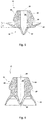
- FIG. 2 shows the combination valve 17 in a state in which it is not installed.
- the umbrella section 20 is already preformed with the manufacture of the combination valve 17 so that it is not flat and plate-shaped, but funnel-shaped and thus shaped like an umbrella and at least partially encloses the base section 19 of the base body 18 of the combination valve 17 on the outside.
- the screen section 20 has a circumferential angle of inclination a, which causes a pre-shaping of the screen section 20, which is formed opposite to the later installation direction of extension of the screen section 20. If the combination valve 17 is inserted into the valve tube 12, the umbrella section 20 turns inside out. In particular, it can be provided that the screen section 20 extends at an angle of more than 90 °, e.g. B.
- FIG Figure 3 shows the combination valve 17 with the base section 19 and with the umbrella section 20 in a state that is approximately assumed when the combination valve 17 is installed and rests on the inside against the wall of the valve tube 12, as in FIG Figure 1 shown.
- the umbrella section 20 is turned inside out in such a way that it extends around the central axis 25 in the direction of the opening side of the bill valve 21, for example in the manner of a sleeve or a pipe section.
- the inclination of the shield section 20 with the angle of inclination a shown in the base body 18 results in a good contact of the shield section 20 on the wall of the valve tube, which has a positive effect on the valve action against the opening in the wall of the valve tube.
- the base section 19 On the side facing away from the bill valve 21, the base section 19 has a mounting cone 40 on the outside circumference in order to insert the base body 18 of the combination valve 17 into the opening of the receiving collar in the valve tube, as shown in FIG Figure 1 shown. That's how it works The combination valve 17 is particularly easy to insert into the valve tube as part of the assembly of the foam pump 1.
- the beak valve and the flutter valve do not necessarily have to be designed as a one-piece combination valve. Rather, they can also be designed in the form of two separately designed components which are each received in the valve tube.
- a turbulence unit is not absolutely necessary. Rather, foam generators can be connected directly to the mixing chamber. As in Figure 1 shown, be arranged in an output-side section of the actuation unit 41. However, these can be arranged differently in the actuation unit 41, e.g. B. both in a section opposite the output end above the actuation plate 37. Furthermore, other functional units can be arranged in the actuation unit 41. For example, an insert or a shape in the form of a constriction can be provided in the area of the dispensing end, whereby, for example, a better tear-off of the dispensed foam can be achieved.
- FIG. 4 a further embodiment of the foam pump 1 according to the invention is shown in a cross-sectional view.
- the structure of the foam pump 1 is similar to that in FIG Figure 1 foam pump shown. However, there are differences in particular in the area of the combination valve 17 and the actuation unit 41.
- the combination valve 17, which is in the Figures 5 and 6 is shown again individually, differs from the embodiment according to FIG Figures 1 to 3 Essentially in that the umbrella section 20 is kept somewhat shorter and, in the installed state, is turned inside out less strongly, whereby a good valve effect of the flutter valve 24 formed with the umbrella section 20 can also be achieved with this less pronounced eversion.
- the screen portion 20 does not directly cover the openings 22 in the wall 23 of the valve tube 12.
- the screen section 20 does not lie flat against the wall 23 around the openings 22. Rather, the shield section 20 lies sealingly against the wall 23 of the valve tube 12 in an area spaced apart from the openings 22. This is also sufficient to be able to selectively establish or close the fluidic connection between the air chamber 14 and the mixing chamber 16.
Landscapes
- Health & Medical Sciences (AREA)
- Public Health (AREA)
- Reciprocating Pumps (AREA)
- Containers And Packaging Bodies Having A Special Means To Remove Contents (AREA)
- Closures For Containers (AREA)
Priority Applications (3)
| Application Number | Priority Date | Filing Date | Title |
|---|---|---|---|
| EP19206040.8A EP3815792B1 (fr) | 2019-10-29 | 2019-10-29 | Pompe à mousse |
| CA3158567A CA3158567C (fr) | 2019-10-29 | 2020-09-22 | Pompe a mousse |
| PCT/EP2020/076419 WO2021083582A1 (fr) | 2019-10-29 | 2020-09-22 | Pompe à mousse |
Applications Claiming Priority (1)
| Application Number | Priority Date | Filing Date | Title |
|---|---|---|---|
| EP19206040.8A EP3815792B1 (fr) | 2019-10-29 | 2019-10-29 | Pompe à mousse |
Publications (2)
| Publication Number | Publication Date |
|---|---|
| EP3815792A1 true EP3815792A1 (fr) | 2021-05-05 |
| EP3815792B1 EP3815792B1 (fr) | 2022-03-30 |
Family
ID=68392823
Family Applications (1)
| Application Number | Title | Priority Date | Filing Date |
|---|---|---|---|
| EP19206040.8A Active EP3815792B1 (fr) | 2019-10-29 | 2019-10-29 | Pompe à mousse |
Country Status (3)
| Country | Link |
|---|---|
| EP (1) | EP3815792B1 (fr) |
| CA (1) | CA3158567C (fr) |
| WO (1) | WO2021083582A1 (fr) |
Cited By (1)
| Publication number | Priority date | Publication date | Assignee | Title |
|---|---|---|---|---|
| EP4659636A1 (fr) * | 2024-06-06 | 2025-12-10 | OP-Hygiene IP GmbH | Distributeur de mousse avec générateur de mousse mobile |
Families Citing this family (1)
| Publication number | Priority date | Publication date | Assignee | Title |
|---|---|---|---|---|
| EP4703045A1 (fr) * | 2024-09-03 | 2026-03-04 | Aptar Radolfzell GmbH | Tête de distribution et distributeur de fluide doté d'une telle tête de distribution |
Citations (2)
| Publication number | Priority date | Publication date | Assignee | Title |
|---|---|---|---|---|
| EP2127756A1 (fr) | 2008-05-28 | 2009-12-02 | Gojo Industries, Inc. | Piston à air et pompe à mousse de dôme |
| EP3085456B1 (fr) | 2015-04-21 | 2018-09-26 | Hübner GmbH & Co. KG | Pompe à mousse |
-
2019
- 2019-10-29 EP EP19206040.8A patent/EP3815792B1/fr active Active
-
2020
- 2020-09-22 WO PCT/EP2020/076419 patent/WO2021083582A1/fr not_active Ceased
- 2020-09-22 CA CA3158567A patent/CA3158567C/fr active Active
Patent Citations (2)
| Publication number | Priority date | Publication date | Assignee | Title |
|---|---|---|---|---|
| EP2127756A1 (fr) | 2008-05-28 | 2009-12-02 | Gojo Industries, Inc. | Piston à air et pompe à mousse de dôme |
| EP3085456B1 (fr) | 2015-04-21 | 2018-09-26 | Hübner GmbH & Co. KG | Pompe à mousse |
Cited By (1)
| Publication number | Priority date | Publication date | Assignee | Title |
|---|---|---|---|---|
| EP4659636A1 (fr) * | 2024-06-06 | 2025-12-10 | OP-Hygiene IP GmbH | Distributeur de mousse avec générateur de mousse mobile |
Also Published As
| Publication number | Publication date |
|---|---|
| CA3158567A1 (fr) | 2021-05-06 |
| EP3815792B1 (fr) | 2022-03-30 |
| CA3158567C (fr) | 2024-10-22 |
| WO2021083582A1 (fr) | 2021-05-06 |
Similar Documents
| Publication | Publication Date | Title |
|---|---|---|
| DE2542851C3 (de) | Handbetätigter Miniaturzerstäuber | |
| DE3104450C2 (de) | Flüssigkeitsinjektor der Drücker-Bauart | |
| DE60102691T2 (de) | Balgpumpe zum spenden von flüssigkeiten | |
| EP2293880B1 (fr) | Tête de décharge de fluide | |
| EP0165949B1 (fr) | Pompe pulverisatrice avec raccord de recipient | |
| DE1907358B2 (de) | Pumpvorrichtung | |
| DE1917392A1 (de) | Pumpe | |
| DE2001921A1 (de) | Hin- und herbewegte Fluessigkeitsabgabepumpe | |
| DE2738766A1 (de) | Ausgabepumpe | |
| DE10259808B4 (de) | Strahlpumpe | |
| DE202008005755U1 (de) | Frischhalte-Vakuum-Abdeckvorrichtung | |
| DE1500597B2 (de) | Tauchrohrzerstäuber | |
| DE1653419A1 (de) | Fluessigkeitsabgabepumpe | |
| EP1834704A2 (fr) | Distributeur de produit fluide | |
| DE202015000521U1 (de) | Ausstoßventilanordnung für ein Flaschenaufsatzgerät | |
| WO2007128741A1 (fr) | Valve auto-obturatrice avec couvercle de valve | |
| DE1282388B (de) | Vorrichtung zur Trennung von Medien unterschiedlicher Viskositaet | |
| EP3815792B1 (fr) | Pompe à mousse | |
| EP0887112A2 (fr) | Distributeur de fluides | |
| DE3834091C2 (fr) | ||
| DE102023204902A1 (de) | Tankventilanordnung und Verfahren zum Betanken eines Gasdruckspeichers | |
| DE102005012506A1 (de) | Abgabevorrichtung | |
| DE1296003B (de) | Verschliesseinrichtung fuer den Behaelterinhalt bei einer Spruehpumpe | |
| DE102010049024B4 (de) | Ventilanordnung für einen Getränkebehälter | |
| DE19728179C2 (de) | Selbsttätig umschaltende Kolben/Zylinderantriebsanordnung, insbesondere für volumetrische Dosiervorrichtungen |
Legal Events
| Date | Code | Title | Description |
|---|---|---|---|
| PUAI | Public reference made under article 153(3) epc to a published international application that has entered the european phase |
Free format text: ORIGINAL CODE: 0009012 |
|
| STAA | Information on the status of an ep patent application or granted ep patent |
Free format text: STATUS: REQUEST FOR EXAMINATION WAS MADE |
|
| 17P | Request for examination filed |
Effective date: 20200803 |
|
| AK | Designated contracting states |
Kind code of ref document: A1 Designated state(s): AL AT BE BG CH CY CZ DE DK EE ES FI FR GB GR HR HU IE IS IT LI LT LU LV MC MK MT NL NO PL PT RO RS SE SI SK SM TR |
|
| REG | Reference to a national code |
Ref country code: DE Ref legal event code: R079 Ref document number: 502019003853 Country of ref document: DE Free format text: PREVIOUS MAIN CLASS: B05B0011000000 Ipc: A47K0005140000 |
|
| RIC1 | Information provided on ipc code assigned before grant |
Ipc: B05B 7/00 20060101ALI20210817BHEP Ipc: B05B 11/00 20060101ALI20210817BHEP Ipc: A47K 5/14 20060101AFI20210817BHEP |
|
| GRAP | Despatch of communication of intention to grant a patent |
Free format text: ORIGINAL CODE: EPIDOSNIGR1 |
|
| STAA | Information on the status of an ep patent application or granted ep patent |
Free format text: STATUS: GRANT OF PATENT IS INTENDED |
|
| INTG | Intention to grant announced |
Effective date: 20211020 |
|
| GRAJ | Information related to disapproval of communication of intention to grant by the applicant or resumption of examination proceedings by the epo deleted |
Free format text: ORIGINAL CODE: EPIDOSDIGR1 |
|
| STAA | Information on the status of an ep patent application or granted ep patent |
Free format text: STATUS: REQUEST FOR EXAMINATION WAS MADE |
|
| GRAP | Despatch of communication of intention to grant a patent |
Free format text: ORIGINAL CODE: EPIDOSNIGR1 |
|
| STAA | Information on the status of an ep patent application or granted ep patent |
Free format text: STATUS: GRANT OF PATENT IS INTENDED |
|
| INTC | Intention to grant announced (deleted) | ||
| INTG | Intention to grant announced |
Effective date: 20220110 |
|
| GRAS | Grant fee paid |
Free format text: ORIGINAL CODE: EPIDOSNIGR3 |
|
| GRAA | (expected) grant |
Free format text: ORIGINAL CODE: 0009210 |
|
| STAA | Information on the status of an ep patent application or granted ep patent |
Free format text: STATUS: THE PATENT HAS BEEN GRANTED |
|
| AK | Designated contracting states |
Kind code of ref document: B1 Designated state(s): AL AT BE BG CH CY CZ DE DK EE ES FI FR GB GR HR HU IE IS IT LI LT LU LV MC MK MT NL NO PL PT RO RS SE SI SK SM TR |
|
| REG | Reference to a national code |
Ref country code: GB Ref legal event code: FG4D Free format text: NOT ENGLISH |
|
| REG | Reference to a national code |
Ref country code: CH Ref legal event code: EP |
|
| REG | Reference to a national code |
Ref country code: AT Ref legal event code: REF Ref document number: 1478423 Country of ref document: AT Kind code of ref document: T Effective date: 20220415 |
|
| REG | Reference to a national code |
Ref country code: DE Ref legal event code: R096 Ref document number: 502019003853 Country of ref document: DE |
|
| REG | Reference to a national code |
Ref country code: IE Ref legal event code: FG4D Free format text: LANGUAGE OF EP DOCUMENT: GERMAN |
|
| REG | Reference to a national code |
Ref country code: LT Ref legal event code: MG9D |
|
| PG25 | Lapsed in a contracting state [announced via postgrant information from national office to epo] |
Ref country code: SE Free format text: LAPSE BECAUSE OF FAILURE TO SUBMIT A TRANSLATION OF THE DESCRIPTION OR TO PAY THE FEE WITHIN THE PRESCRIBED TIME-LIMIT Effective date: 20220330 Ref country code: RS Free format text: LAPSE BECAUSE OF FAILURE TO SUBMIT A TRANSLATION OF THE DESCRIPTION OR TO PAY THE FEE WITHIN THE PRESCRIBED TIME-LIMIT Effective date: 20220330 Ref country code: NO Free format text: LAPSE BECAUSE OF FAILURE TO SUBMIT A TRANSLATION OF THE DESCRIPTION OR TO PAY THE FEE WITHIN THE PRESCRIBED TIME-LIMIT Effective date: 20220630 Ref country code: LT Free format text: LAPSE BECAUSE OF FAILURE TO SUBMIT A TRANSLATION OF THE DESCRIPTION OR TO PAY THE FEE WITHIN THE PRESCRIBED TIME-LIMIT Effective date: 20220330 Ref country code: HR Free format text: LAPSE BECAUSE OF FAILURE TO SUBMIT A TRANSLATION OF THE DESCRIPTION OR TO PAY THE FEE WITHIN THE PRESCRIBED TIME-LIMIT Effective date: 20220330 Ref country code: BG Free format text: LAPSE BECAUSE OF FAILURE TO SUBMIT A TRANSLATION OF THE DESCRIPTION OR TO PAY THE FEE WITHIN THE PRESCRIBED TIME-LIMIT Effective date: 20220630 |
|
| REG | Reference to a national code |
Ref country code: NL Ref legal event code: MP Effective date: 20220330 |
|
| PG25 | Lapsed in a contracting state [announced via postgrant information from national office to epo] |
Ref country code: LV Free format text: LAPSE BECAUSE OF FAILURE TO SUBMIT A TRANSLATION OF THE DESCRIPTION OR TO PAY THE FEE WITHIN THE PRESCRIBED TIME-LIMIT Effective date: 20220330 Ref country code: GR Free format text: LAPSE BECAUSE OF FAILURE TO SUBMIT A TRANSLATION OF THE DESCRIPTION OR TO PAY THE FEE WITHIN THE PRESCRIBED TIME-LIMIT Effective date: 20220701 Ref country code: FI Free format text: LAPSE BECAUSE OF FAILURE TO SUBMIT A TRANSLATION OF THE DESCRIPTION OR TO PAY THE FEE WITHIN THE PRESCRIBED TIME-LIMIT Effective date: 20220330 |
|
| PG25 | Lapsed in a contracting state [announced via postgrant information from national office to epo] |
Ref country code: NL Free format text: LAPSE BECAUSE OF FAILURE TO SUBMIT A TRANSLATION OF THE DESCRIPTION OR TO PAY THE FEE WITHIN THE PRESCRIBED TIME-LIMIT Effective date: 20220330 |
|
| PG25 | Lapsed in a contracting state [announced via postgrant information from national office to epo] |
Ref country code: SM Free format text: LAPSE BECAUSE OF FAILURE TO SUBMIT A TRANSLATION OF THE DESCRIPTION OR TO PAY THE FEE WITHIN THE PRESCRIBED TIME-LIMIT Effective date: 20220330 Ref country code: SK Free format text: LAPSE BECAUSE OF FAILURE TO SUBMIT A TRANSLATION OF THE DESCRIPTION OR TO PAY THE FEE WITHIN THE PRESCRIBED TIME-LIMIT Effective date: 20220330 Ref country code: RO Free format text: LAPSE BECAUSE OF FAILURE TO SUBMIT A TRANSLATION OF THE DESCRIPTION OR TO PAY THE FEE WITHIN THE PRESCRIBED TIME-LIMIT Effective date: 20220330 Ref country code: PT Free format text: LAPSE BECAUSE OF FAILURE TO SUBMIT A TRANSLATION OF THE DESCRIPTION OR TO PAY THE FEE WITHIN THE PRESCRIBED TIME-LIMIT Effective date: 20220801 Ref country code: ES Free format text: LAPSE BECAUSE OF FAILURE TO SUBMIT A TRANSLATION OF THE DESCRIPTION OR TO PAY THE FEE WITHIN THE PRESCRIBED TIME-LIMIT Effective date: 20220330 Ref country code: EE Free format text: LAPSE BECAUSE OF FAILURE TO SUBMIT A TRANSLATION OF THE DESCRIPTION OR TO PAY THE FEE WITHIN THE PRESCRIBED TIME-LIMIT Effective date: 20220330 Ref country code: CZ Free format text: LAPSE BECAUSE OF FAILURE TO SUBMIT A TRANSLATION OF THE DESCRIPTION OR TO PAY THE FEE WITHIN THE PRESCRIBED TIME-LIMIT Effective date: 20220330 |
|
| PG25 | Lapsed in a contracting state [announced via postgrant information from national office to epo] |
Ref country code: PL Free format text: LAPSE BECAUSE OF FAILURE TO SUBMIT A TRANSLATION OF THE DESCRIPTION OR TO PAY THE FEE WITHIN THE PRESCRIBED TIME-LIMIT Effective date: 20220330 Ref country code: IS Free format text: LAPSE BECAUSE OF FAILURE TO SUBMIT A TRANSLATION OF THE DESCRIPTION OR TO PAY THE FEE WITHIN THE PRESCRIBED TIME-LIMIT Effective date: 20220730 Ref country code: AL Free format text: LAPSE BECAUSE OF FAILURE TO SUBMIT A TRANSLATION OF THE DESCRIPTION OR TO PAY THE FEE WITHIN THE PRESCRIBED TIME-LIMIT Effective date: 20220330 |
|
| REG | Reference to a national code |
Ref country code: DE Ref legal event code: R097 Ref document number: 502019003853 Country of ref document: DE |
|
| PG25 | Lapsed in a contracting state [announced via postgrant information from national office to epo] |
Ref country code: DK Free format text: LAPSE BECAUSE OF FAILURE TO SUBMIT A TRANSLATION OF THE DESCRIPTION OR TO PAY THE FEE WITHIN THE PRESCRIBED TIME-LIMIT Effective date: 20220330 |
|
| PLBE | No opposition filed within time limit |
Free format text: ORIGINAL CODE: 0009261 |
|
| STAA | Information on the status of an ep patent application or granted ep patent |
Free format text: STATUS: NO OPPOSITION FILED WITHIN TIME LIMIT |
|
| 26N | No opposition filed |
Effective date: 20230103 |
|
| PG25 | Lapsed in a contracting state [announced via postgrant information from national office to epo] |
Ref country code: SI Free format text: LAPSE BECAUSE OF FAILURE TO SUBMIT A TRANSLATION OF THE DESCRIPTION OR TO PAY THE FEE WITHIN THE PRESCRIBED TIME-LIMIT Effective date: 20220330 Ref country code: MC Free format text: LAPSE BECAUSE OF FAILURE TO SUBMIT A TRANSLATION OF THE DESCRIPTION OR TO PAY THE FEE WITHIN THE PRESCRIBED TIME-LIMIT Effective date: 20220330 |
|
| PG25 | Lapsed in a contracting state [announced via postgrant information from national office to epo] |
Ref country code: LU Free format text: LAPSE BECAUSE OF NON-PAYMENT OF DUE FEES Effective date: 20221029 |
|
| PG25 | Lapsed in a contracting state [announced via postgrant information from national office to epo] |
Ref country code: IT Free format text: LAPSE BECAUSE OF FAILURE TO SUBMIT A TRANSLATION OF THE DESCRIPTION OR TO PAY THE FEE WITHIN THE PRESCRIBED TIME-LIMIT Effective date: 20220330 |
|
| P01 | Opt-out of the competence of the unified patent court (upc) registered |
Effective date: 20230911 |
|
| PG25 | Lapsed in a contracting state [announced via postgrant information from national office to epo] |
Ref country code: CY Free format text: LAPSE BECAUSE OF FAILURE TO SUBMIT A TRANSLATION OF THE DESCRIPTION OR TO PAY THE FEE WITHIN THE PRESCRIBED TIME-LIMIT Effective date: 20220330 |
|
| PG25 | Lapsed in a contracting state [announced via postgrant information from national office to epo] |
Ref country code: MK Free format text: LAPSE BECAUSE OF FAILURE TO SUBMIT A TRANSLATION OF THE DESCRIPTION OR TO PAY THE FEE WITHIN THE PRESCRIBED TIME-LIMIT Effective date: 20220330 Ref country code: HU Free format text: LAPSE BECAUSE OF FAILURE TO SUBMIT A TRANSLATION OF THE DESCRIPTION OR TO PAY THE FEE WITHIN THE PRESCRIBED TIME-LIMIT; INVALID AB INITIO Effective date: 20191029 |
|
| PG25 | Lapsed in a contracting state [announced via postgrant information from national office to epo] |
Ref country code: TR Free format text: LAPSE BECAUSE OF FAILURE TO SUBMIT A TRANSLATION OF THE DESCRIPTION OR TO PAY THE FEE WITHIN THE PRESCRIBED TIME-LIMIT Effective date: 20220330 |
|
| PG25 | Lapsed in a contracting state [announced via postgrant information from national office to epo] |
Ref country code: MT Free format text: LAPSE BECAUSE OF FAILURE TO SUBMIT A TRANSLATION OF THE DESCRIPTION OR TO PAY THE FEE WITHIN THE PRESCRIBED TIME-LIMIT Effective date: 20220330 |
|
| REG | Reference to a national code |
Ref country code: CH Ref legal event code: U11 Free format text: ST27 STATUS EVENT CODE: U-0-0-U10-U11 (AS PROVIDED BY THE NATIONAL OFFICE) Effective date: 20251101 |
|
| REG | Reference to a national code |
Ref country code: AT Ref legal event code: MM01 Ref document number: 1478423 Country of ref document: AT Kind code of ref document: T Effective date: 20241029 |
|
| PGFP | Annual fee paid to national office [announced via postgrant information from national office to epo] |
Ref country code: DE Payment date: 20251020 Year of fee payment: 7 |
|
| PGFP | Annual fee paid to national office [announced via postgrant information from national office to epo] |
Ref country code: GB Payment date: 20251024 Year of fee payment: 7 |
|
| PG25 | Lapsed in a contracting state [announced via postgrant information from national office to epo] |
Ref country code: AT Free format text: LAPSE BECAUSE OF NON-PAYMENT OF DUE FEES Effective date: 20241029 |
|
| PGFP | Annual fee paid to national office [announced via postgrant information from national office to epo] |
Ref country code: FR Payment date: 20251029 Year of fee payment: 7 |
|
| PGFP | Annual fee paid to national office [announced via postgrant information from national office to epo] |
Ref country code: BE Payment date: 20251022 Year of fee payment: 7 |
|
| PGFP | Annual fee paid to national office [announced via postgrant information from national office to epo] |
Ref country code: CH Payment date: 20251101 Year of fee payment: 7 |
|
| PGFP | Annual fee paid to national office [announced via postgrant information from national office to epo] |
Ref country code: IE Payment date: 20251021 Year of fee payment: 7 |
|
| PGFP | Annual fee paid to national office [announced via postgrant information from national office to epo] |
Ref country code: AT Payment date: 20260410 Year of fee payment: 5 |