EP3815865A1 - Dispositif de coffrage - Google Patents
Dispositif de coffrage Download PDFInfo
- Publication number
- EP3815865A1 EP3815865A1 EP19206423.6A EP19206423A EP3815865A1 EP 3815865 A1 EP3815865 A1 EP 3815865A1 EP 19206423 A EP19206423 A EP 19206423A EP 3815865 A1 EP3815865 A1 EP 3815865A1
- Authority
- EP
- European Patent Office
- Prior art keywords
- formwork
- elements
- formwork elements
- end regions
- spreading
- Prior art date
- Legal status (The legal status is an assumption and is not a legal conclusion. Google has not performed a legal analysis and makes no representation as to the accuracy of the status listed.)
- Withdrawn
Links
- 238000009415 formwork Methods 0.000 title claims abstract description 351
- 230000007480 spreading Effects 0.000 claims abstract description 96
- 239000011178 precast concrete Substances 0.000 claims abstract description 41
- 238000004519 manufacturing process Methods 0.000 claims abstract description 15
- 238000000034 method Methods 0.000 claims abstract description 11
- 239000004567 concrete Substances 0.000 claims abstract description 9
- 238000001035 drying Methods 0.000 claims description 19
- 238000009416 shuttering Methods 0.000 claims description 13
- 239000000758 substrate Substances 0.000 claims description 9
- 230000006835 compression Effects 0.000 description 6
- 238000007906 compression Methods 0.000 description 6
- 230000008878 coupling Effects 0.000 description 3
- 238000010168 coupling process Methods 0.000 description 3
- 238000005859 coupling reaction Methods 0.000 description 3
- 238000005192 partition Methods 0.000 description 3
- 206010013786 Dry skin Diseases 0.000 description 1
- 229920002430 Fibre-reinforced plastic Polymers 0.000 description 1
- 230000008901 benefit Effects 0.000 description 1
- 238000006243 chemical reaction Methods 0.000 description 1
- 230000000694 effects Effects 0.000 description 1
- 230000002349 favourable effect Effects 0.000 description 1
- 239000011151 fibre-reinforced plastic Substances 0.000 description 1
- 230000005484 gravity Effects 0.000 description 1
- 238000010438 heat treatment Methods 0.000 description 1
- 239000000463 material Substances 0.000 description 1
- 239000002184 metal Substances 0.000 description 1
- 239000004033 plastic Substances 0.000 description 1
- 229920003023 plastic Polymers 0.000 description 1
- 230000008569 process Effects 0.000 description 1
- 230000000284 resting effect Effects 0.000 description 1
- 230000006641 stabilisation Effects 0.000 description 1
- 238000011105 stabilization Methods 0.000 description 1
- 230000001960 triggered effect Effects 0.000 description 1
Images


Classifications
-
- B—PERFORMING OPERATIONS; TRANSPORTING
- B28—WORKING CEMENT, CLAY, OR STONE
- B28B—SHAPING CLAY OR OTHER CERAMIC COMPOSITIONS; SHAPING SLAG; SHAPING MIXTURES CONTAINING CEMENTITIOUS MATERIAL, e.g. PLASTER
- B28B7/00—Moulds; Cores; Mandrels
- B28B7/24—Unitary mould structures with a plurality of moulding spaces, e.g. moulds divided into multiple moulding spaces by integratable partitions, mould part structures providing a number of moulding spaces in mutual co-operation
- B28B7/241—Detachable assemblies of mould parts providing only in mutual co-operation a number of complete moulding spaces
- B28B7/243—Detachable assemblies of mould parts providing only in mutual co-operation a number of complete moulding spaces for making plates, panels or similar sheet- or disc-shaped objects
- B28B7/245—Detachable assemblies of mould parts providing only in mutual co-operation a number of complete moulding spaces for making plates, panels or similar sheet- or disc-shaped objects using transportable mould batteries
-
- B—PERFORMING OPERATIONS; TRANSPORTING
- B28—WORKING CEMENT, CLAY, OR STONE
- B28B—SHAPING CLAY OR OTHER CERAMIC COMPOSITIONS; SHAPING SLAG; SHAPING MIXTURES CONTAINING CEMENTITIOUS MATERIAL, e.g. PLASTER
- B28B7/00—Moulds; Cores; Mandrels
- B28B7/0002—Auxiliary parts or elements of the mould
- B28B7/0014—Fastening means for mould parts, e.g. for attaching mould walls on mould tables; Mould clamps
- B28B7/002—Fastening means for mould parts, e.g. for attaching mould walls on mould tables; Mould clamps using magnets
-
- B—PERFORMING OPERATIONS; TRANSPORTING
- B28—WORKING CEMENT, CLAY, OR STONE
- B28B—SHAPING CLAY OR OTHER CERAMIC COMPOSITIONS; SHAPING SLAG; SHAPING MIXTURES CONTAINING CEMENTITIOUS MATERIAL, e.g. PLASTER
- B28B7/00—Moulds; Cores; Mandrels
- B28B7/08—Moulds provided with means for tilting or inverting
- B28B7/082—Tiltable moulding tables or similar moulding surfaces
-
- B—PERFORMING OPERATIONS; TRANSPORTING
- B28—WORKING CEMENT, CLAY, OR STONE
- B28B—SHAPING CLAY OR OTHER CERAMIC COMPOSITIONS; SHAPING SLAG; SHAPING MIXTURES CONTAINING CEMENTITIOUS MATERIAL, e.g. PLASTER
- B28B7/00—Moulds; Cores; Mandrels
- B28B7/24—Unitary mould structures with a plurality of moulding spaces, e.g. moulds divided into multiple moulding spaces by integratable partitions, mould part structures providing a number of moulding spaces in mutual co-operation
- B28B7/241—Detachable assemblies of mould parts providing only in mutual co-operation a number of complete moulding spaces
- B28B7/243—Detachable assemblies of mould parts providing only in mutual co-operation a number of complete moulding spaces for making plates, panels or similar sheet- or disc-shaped objects
Definitions
- the invention relates to a formwork device, in particular for arrangement between two bulkheads of a battery formwork, for the production of structural elements, in particular precast concrete parts, comprising: two formwork elements, in particular formwork panels, each having a formwork front side for loading with concrete and a formwork rear side, the formwork elements being pivotably connected to one another at first end areas so that the formwork elements can be converted from a standing state to a lying state.
- the invention further relates to a battery formwork which has two bulkheads and a formwork device that can be arranged between the bulkheads.
- the invention relates to a method for producing a precast concrete part, as well as a method for preparing the production of a precast concrete part.
- Battery molds are often used in the series production of precast concrete parts.
- Precast concrete parts are often used, particularly in the manufacture of prefabricated buildings. These precast concrete parts can be produced quickly and cheaply in battery molds.
- the WO 2016/184947 A1 shows a battery formwork with a support device into which formwork devices are suspended from above. These formwork devices each have two formwork panels which are articulated to one another on one longitudinal side in order to be converted from an unfolded state into a folded state.
- Each formwork panel has a formwork front side for attaching formwork elements and a formwork rear side, with the formwork rear sides of the formwork panels facing one another in the folded state of the formwork device.
- the formwork devices are fitted on a substrate in the unfolded state, with formwork elements being attached to the formwork fronts of the horizontally aligned formwork panels that are pointing upwards. Thereafter, the formwork devices are raised with the aid of a lifting device, whereby the rear side of the formwork panels fold up.
- the formwork panels are so between two Partition walls positioned so that cavities form between the formwork fronts, the formwork elements and the partition walls, which are filled with concrete.
- the precast concrete parts can be hardened within the battery mold.
- the disadvantage here is that the entire battery mold is in use until the concrete has hardened and cannot be used for pouring further precast concrete parts.
- the object of the present invention is to alleviate or remedy at least individual disadvantages of the prior art.
- the aim of the invention is, in particular, to enable the battery mold to be reused more quickly and to simplify the removal of the precast concrete parts.
- Another aim can be to make it easier to move the formwork elements into the lying position for fitting with delimiting elements for doors, windows, etc.
- a formwork device with the features of claim 1, a battery formwork with the features of claim 11, a method for producing a precast concrete part with the features of claim 12 and a method for preparing the production of a precast concrete part with the features of claim 14 .
- the formwork device has a spreading device for spreading apart the second end areas of the formwork elements, which are opposite the first end areas, starting from the standing state of the formwork elements.
- This formwork device can be used in particular in a battery formwork with two bulkheads.
- the two preferably rectangular formwork elements are each pivotably connected at a first end region, in particular on one of their longitudinal sides.
- an articulated connection can be provided between the first end regions of the formwork elements.
- the two formwork elements can be transferred from a standing state, in which the formwork elements are preferably aligned essentially vertically, to a lying state, in which the formwork elements are preferably aligned essentially horizontally.
- the first end areas form the upper ends of the formwork elements and the second end areas form the lower ends of the formwork elements.
- the formwork elements can be arranged in the standing state between the two bulkheads of the battery formwork.
- the formwork elements are in the collapsed (i.e. essentially parallel side by side) state, with the formwork fronts pointing outwards and the formwork backs facing each other.
- the two front sides of the formwork delimit cavities into which concrete can be poured.
- the lying state of the formwork elements can be used to attach formwork elements, that is to say in particular delimitation elements for door and / or window cutouts in the component, to the formwork front sides of the formwork elements.
- the spreading device according to the invention at the second end regions of the formwork elements can advantageously fulfill different functions depending on the design.
- the formwork device can be removed from the interior of the battery formwork, in particular lifted out with a lifting device, together with at least one component on a formwork front, in particular two components on the two formwork fronts.
- the precast concrete parts are included in a cured, but not yet completely dried state, which allows the component to be held on the respective front side of the formwork without counterpressure by the bulkheads (or other formwork devices).
- the formwork device can be arranged in a drying position with the second end regions of the formwork elements spread apart outside the space between the battery formwork.
- the spreading device engages the second end regions - opposite the pivotable connection between the formwork elements - at least while the shuttering device is being set down with the component to be dried on the substrate.
- the second end regions of the formwork elements are spread apart, so that the two formwork elements form an inverted V-shape when viewed from the side in the drying position.
- the drying position is a stable intermediate position between the standing and lying position of the formwork elements.
- the formwork device can thus be arranged in the stable and space-saving drying position outside the interior of the battery formwork in order to dry the components. Meanwhile, the interior of the battery mold can already be used for the production of further components.
- the spreading device In the drying position, the spreading device has the effect that the second end regions of the formwork elements are secured against collapsing into the standing state and / or unfolding into the lying state.
- the spreading device first drives the second end regions of the formwork elements apart and then holds the formwork elements in the drying position.
- the drying position is preferably closer, in particular several times closer, to the standing state than to the lying state of the formwork elements in relation to the pivoting angle.
- This embodiment also has the advantage that lifting the component away from the formwork device after drying is made much easier because the component is only exposed to low loads and, moreover, a disadvantageous tumbling of the component is avoided.
- the spreading device can also be used to transfer the formwork elements from to accomplish the standing state in the direction of the lying state.
- a manual unfolding of the formwork elements can advantageously be avoided.
- the location and direction information refer to an intended operating position of the formwork device and the battery position on a horizontal surface.
- the formwork elements are therefore arranged with the aid of the spreading device in the drying position with the second end regions spread apart.
- the spreading device connects the second end areas of the formwork elements with one another in such a way that the second end areas are transferred from the standing position to the drying position, but not further in the direction of the lying position, in order to be placed in a stable triangular arrangement on a level surface can.
- the spreading device is preferably detachably attached to the second end regions of the formwork elements before the formwork elements are placed on the ground with the spreading device.
- the contact of the spreading device on the second end regions of the formwork elements can be used with the subsurface to convert the lowering movement of the formwork device into the spreading of the second end regions of the formwork elements.
- the spreading device is used to transfer the formwork elements from the standing position to the lying position.
- the formwork elements are preferably arranged above the ground, in particular with the aid of a lifting device, for example a crane.
- the spreader is meanwhile on the ground.
- the spreading device is actuated in such a way that the second end regions of the formwork elements are transferred from the standing state in the direction of the lying state.
- this can at least partially cause the formwork elements to unfold.
- the spreading device can also be used when folding in the formwork elements, i.e. when moving from the lying to the standing position.
- the spreading device has a force deflection device which acts on the second end regions of the formwork elements and which lowers the formwork elements in the spreading of the second end regions of the Converts formwork elements.
- the lowering movement, i.e. the vertical downward movement, of the formwork elements can cause the second end areas of the formwork elements to spread apart through the contact of the spreading device at the second end areas with the ground or by lowering the formwork elements onto the spreading device previously placed on the ground.
- the energy released by the vertical downward movement can be used to spread the second end regions of the formwork elements apart.
- the force deflection device has two lever elements which are connected to one another via a pivot bearing with a pivot axis that is preferably essentially stationary when the formwork elements are spread apart.
- the second end regions of the formwork elements can be spread apart particularly easily.
- the impact of the spreading device attached to the second end areas on the ground or the lowering of the formwork elements on the spreading device located on the ground is converted into a pivoting of the lever elements, which causes the second end areas of the formwork elements to spread apart.
- the two lever elements are preferably connected to one another in a pivotable manner by means of a pivot axis on the subsurface side.
- the spreading device in particular its lever elements, can be made of different materials.
- An embodiment made of metal, plastic, in particular fiber-reinforced plastic, or a combination thereof is preferred.
- two spreading devices are provided for engaging the lateral edges on the second end regions of the formwork elements.
- the two spreading devices advantageously engage on two opposite sides of the lateral edges on the second end regions of the formwork elements. A uniform spreading of the formwork elements over the entire length of the formwork device (ie its extension along the pivotable connection) can thus be ensured.
- the lever elements are arranged essentially horizontally in the spread apart state of the second end regions of the formwork elements.
- the two lever elements are preferably arranged in a V-shaped position in the rest state, i.e. before the two end regions are spread apart.
- the lever elements are transferred from the rest state, in which they grip the second end areas of the formwork elements in the standing state, to the horizontal position in which the second end areas of the formwork elements are spread apart and the two lever elements are at an angle of substantially 180 ° include.
- the two lever elements pivot in opposite directions about the pivot axis.
- the two formwork elements together with the horizontally aligned lever elements have the shape of an isosceles triangle, the horizontally aligned lever elements forming the base and the formwork elements forming the legs.
- the formwork elements each have a connection element at the second end regions for the preferably detachable connection to the expansion device.
- two connecting straps are provided as connecting elements, which are pivotably connected to the lever elements.
- a lever element and a connecting strap each form a toggle lever.
- the lever elements and the connecting elements can be connected to one another or are connected to one another via bolt connections, in particular with bolts and bolt receptacles.
- the lever elements and the connecting elements can be detachably connected to one another in a simple manner.
- a bolt is preferably inserted into a corresponding bolt receptacle.
- the pivot bearing has a preferably has a substantially horizontal support surface for resting on the ground when lowering the formwork elements with the spreading device attached to them.
- the lever elements are pivoted apart due to the contact with the ground and thus the second end regions of the formwork elements are spread apart.
- the lever elements have receiving depressions for receiving corresponding guide elements, in particular guide bolts, on the second end regions of the formwork elements.
- formwork elements can be precisely aligned with respect to the spreading device. This design is particularly suitable when the spreading device is initially arranged separately, i.e. at a distance from the formwork elements on the ground, and the formwork elements are then lowered onto the spreading device in order to remove the second end areas from one another by means of the spreading device.
- a tensioning device in particular a spring, is provided for biasing the lever elements in the direction of a rest position of the lever elements before the second end regions of the formwork elements are spread apart.
- the spring is tensioned by the second end regions spreading apart.
- the lever elements are relaxed in the vertical position and can accommodate the formwork elements in the standing position.
- the lever elements are moved into the horizontal position against a spring force of the spring, so that the released energy of the lowering movement of the formwork elements is absorbed by the spring in order to tension it.
- a releasable locking device is provided for locking the pivoting of the lever elements in their rest position. This prevents the lever elements from moving before the formwork elements are arranged on the spreading device.
- an opening device is provided for transferring the formwork elements from the spread-apart state of the second end regions to the lying state of the formwork elements.
- the formwork elements can be transferred to the lying position in order to clean them and to equip them with new formwork elements, such as limiting elements for windows and / or doors.
- the opening device has at least one guide track for guiding support elements, in particular support rollers, on the second end regions of the formwork elements.
- the formwork elements are moved from the spread apart state of the second end regions by means of the opening device into the lying state of the formwork elements.
- the formwork elements can then be fitted with formwork elements. This design is particularly advantageous in connection with the lever elements of the spreading device, because comparatively short lever elements can be used in this way.
- the at least one guide track has at least one sloping takeover section for taking over the support elements, in particular support rollers. This allows the formwork elements to be guided from the standing to the lying position in a controlled manner.
- the locking device has a hook and a corresponding receiving device for receiving the hook, the hook being arranged on one of the two lever elements and the receiving device being arranged on the other of the two lever elements is.
- a locking of the lever elements can thereby be achieved in a simple manner.
- the lever elements can be moved against one another.
- the hook is advantageously automatically released from the corresponding receiving device, so that the second end regions of the formwork elements can be spread apart with the aid of the lever devices.
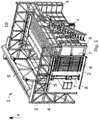
- Fig. 1 shows a schematic representation of an example from FIG WO 2017/174432 known battery formwork 1 with formwork devices 2.
- the battery formwork 1 is used for the production of components, not shown, and in particular of precast concrete parts for buildings.
- the battery mold 1 has a support frame 3 with spaced-apart support sections 4.
- the number of support sections 4 in Fig. 1 is only to be regarded as an example and can be adapted to the circumstances.
- the battery formwork 1 comprises two support devices 5, in which the bulkheads 6 and the formwork devices 2 are accommodated in a hanging and movable manner, ie in the present embodiment they can be displaced.
- the shuttering devices 2 are located between the bulkheads 6.
- a cavity to be filled with concrete is formed between at least one bulkhead 6 and a shuttering device 2, the shuttering device 2 preferably carrying shuttering elements (not shown) that determine the contour of the precast concrete part.
- the formwork elements can, for example, delimit door or window cutouts and also seal the cavity filled with concrete during concreting.
- the formwork elements can be attached to the formwork device 2 with magnetic holders, for example.
- a heating device (not shown) and / or a vibrator (not shown) can also be mounted on the formwork device 2.
- the formwork equipment 2 is used between two bulkheads 6 and braced with them during concreting.
- the number of support devices 5 of the bulkheads 6 and the formwork devices 2 is to be regarded as only exemplary and can be varied depending on the circumstances.
- formwork devices 2 can be provided for concreting the outer walls, inner walls, the floor and the roof of a house, so that the components for an entire building can be produced simultaneously with the battery formwork 1.
- the bulkheads 6 and the formwork devices 2 are clamped between two support devices 7.
- the number of support devices 7 is also to be regarded as only exemplary and can be varied according to requirements. At least one support device 7 is movable, i. H. displaceable in the present embodiment, received in the support devices 5.
- the formwork devices 2 and the support devices 7 can be connected to one another and braced in the concreting position by one or more rod-shaped connecting devices 8.
- the number of connecting devices 8 can be adapted to the circumstances. Instead of rod-shaped connecting devices 8, hydraulic connecting devices are also possible.
- the rod-shaped connecting devices 8 are, however, particularly robust and easy to handle.
- the battery formwork 1 has a lifting device 9, with which at least one of the formwork devices 2 can be transferred from the lowered concreting position to a raised transport position, in which the formwork device 2 in a direction essentially perpendicular to the lifting direction X via a formwork device 2 in the concreting position is fundable.
- the formwork devices 2 are hooked into the support devices 5 from above, so that in the hooked-in state in the concreting position they are spaced from the ground between the support sections 4.
- the design of the lifting device 9 can be adapted to the requirements. If necessary, several lifting devices 9 can also be used.
- the lifting device 9 is on two spaced apart guide devices 10, which are designed here as running rails are movable in a tensioning direction of the formwork devices 2. Furthermore, the guide devices 10 are arranged above the support devices 5 and parallel to them. In order to make the battery formwork 1 more compact, the formwork devices 2 are attached to the support devices 5 at their upper end.
- the formwork devices 2 of the Fig. 1 can be included in the battery formwork 1, which are explained in the following.
- Fig. 2 shows a formwork device 2 for arrangement between two bulkheads 6 of a battery formwork 1 according to Fig. 1 .
- the bulkheads 6 can also be designed as further formwork elements.
- the formwork device 2 has two formwork elements 11 which, in the embodiment shown, are formwork panels.
- the formwork elements 11 each have a formwork front side 12 for loading with concrete and a formwork rear side 13, the formwork elements 11 being pivotably connected to one another at first end regions 14 so that the formwork elements 11 can be converted from a standing state to a lying state.
- the formwork elements 11 each have two connecting elements 16 at the second end areas 15 opposite the first end areas 14, which are arranged at the two ends of the lower longitudinal edges 17 of the formwork elements 11.
- Fig. 2 shows a formwork device 2 according to the invention, in which at least one spreading device 18 for spreading apart the second end regions 15 of the formwork elements 11 (cf. Fig. 6 ) starting from the standing state of the formwork elements 11 is used.
- Two spreading devices 18 are preferably provided at a horizontal distance from one another.
- the spreading devices 18 are releasably connected to the connecting elements 16 of the shuttering devices 11.
- the spreading device 18 has a force deflection device 19 which engages the second end regions 15 of the formwork elements 11 and which lowers the formwork elements 11 by spreading the second end regions 15 apart the formwork elements 11 converts.
- the force deflection device 19 has two lever elements 20 which are connected to one another via a pivot bearing 21 with a pivot axis 22 which is essentially stationary when the formwork elements 11 are spread apart.
- 16 connecting straps are provided as connecting elements to which the lever elements 20 are pivotably attached.
- releasable bolt connections are provided between the spreading device 18 and the connecting elements 16 on the formwork elements 11.
- the bolt connections have bolts 23 and corresponding bolt receptacles.
- a lever element 20 and a connecting strap each form a toggle lever.
- the pivot bearing 21 has an essentially horizontal bearing surface 24 for bearing on the ground when the formwork elements 11 are lowered with the spreading device 18 attached to them.
- Fig. 2 the formwork elements 11 are arranged vertically in the standing state so that the formwork backs 13 face each other and the formwork fronts 12 face these when the formwork device 2 is arranged in a battery formwork 1 between two bulkheads 6.
- FIG. 2 In the right position of the Fig. 2 the placement of the spreading device 18 on the ground is shown, whereby the spreading apart of the second end regions 15 of the formwork elements 11 is triggered.
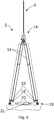
- Fig. 3 shows the conversion of the lowering movement of the formwork device 2 with the spreading device 18 into the spreading apart of the second end regions 15 of the formwork elements 11.
- lever elements 20 are arranged essentially horizontally in the spread apart state of the second end regions 15 of the formwork elements 11.
- the following process can therefore be carried out to produce and dry a precast concrete part.
- the formwork device 2 is in the battery formwork 1 according to Fig. 1 arranged, the formwork elements 11 of the formwork device 2 in a concreting position in an interior space between the two Partition walls 6 are arranged. Then at least one precast concrete part is poured with the aid of the formwork device 2, a precast concrete part preferably being formed on each of the two formwork elements 11.
- the formwork device 2 can be used to produce two precast concrete parts at the same time. With the arrangement of several formwork devices 2 between several bulkheads 6 in the battery formwork 1, a corresponding number of precast concrete parts can be poured.
- the formwork device 2 together with at least one precast concrete part is made using a lifting device, for example the lifting device 9 according to FIG Fig. 1 , lifted out of the interior of the battery casing.
- the formwork elements 11 is in a standing state in which the formwork elements 11, as in FIG Fig. 2 shown, are arranged vertically collapsed.
- two spreading devices 18 according to Figs. 2 to 4 connected to the second end regions 15 of the formwork elements 11 at the two ends of the longitudinal sides 17 of the formwork elements 11, with bolts 23 being brought into engagement with corresponding bolt receptacles. This bolt connection can be secured with the help of splints.
- the bolts 23 are provided on the connecting elements 16 and the bolt receptacles are provided on the lever elements 20.
- An interchanged arrangement can of course also be provided.
- the bolts 23 can be releasably arranged in corresponding bolt receptacles of the connecting elements 16 and the lever elements 20.
- the formwork elements 11 with the precast concrete part and the spreading devices 18 are arranged at the second end regions 15 of the formwork elements 11 in a drying position on a substrate outside the interior of the battery formwork 1.
- the formwork elements 11 are moved in the standing state with expanding tools 18 arranged on the connecting elements 16 with the aid of the lifting device 9 downwards in the direction of a subsurface until, as in FIG Fig.
- the horizontal support surface 24 rests on the ground.
- the second end regions 15 of the formwork elements 11 are spread apart by the spreading device 18 by, as shown in FIG Fig. 3 shown, by the weight of the formwork elements 11 these are moved downwards. Due to the stationary pivot axis 22 of the lever elements 20 of the spreading device 18 and the articulated connection between the lever elements 20 and the connecting elements 16 in the second end area 15 of the formwork elements 11 are spread apart in the second end areas 15 when the formwork elements 11 are lowered. As a result, the lowering movement of the formwork elements 11 when they are arranged on the ground is converted into the spreading apart of the second end regions 15 of the formwork elements 11.
- the formwork elements 11 are lowered and spread until the connecting elements 16 of the formwork elements 11 rest on the ground.
- the lever elements 20 are aligned horizontally so that the two lever elements 20 enclose an angle of 180 °. This prevents the formwork elements 11 from spreading further apart, so that the formwork device 2 assumes a stable drying position and the lifting device 9 can be removed without the formwork device 2 tipping over.
- Fig. 5 shows a further spreading device 18 according to the invention, which has a force deflection device 19 with two lever elements 20 which are connected to one another via a swivel bearing 21 with a swivel axis 22 which is essentially stationary when the formwork elements 11 are spread apart.
- the lever elements 20 are here, however, much longer than in the embodiment of FIG Figs. 2 to 4 educated.
- the lever elements 20 have receiving troughs 25 for receiving corresponding guide bolts on the second end regions 15 of the formwork elements 11 (cf. Fig. 7 ).
- the spreading device 18 has an opening device 26 for transferring the formwork elements 11 from the spread-apart state of the second end regions 15 into the lying state of the formwork elements 11.
- the opening device 26 comprises a guide track 27 for guiding support elements 28 on the second end regions 15 of the formwork elements 11, the guide track 27 having two sloping takeover sections 29 for taking over the support elements 28.
- the spreading device 18 has a tensioning device 30 which has a spring.
- the tensioning device 30 serves to pretension the lever elements 20 in the direction of a rest position of the lever elements 20 before they are spread apart of the second end regions 15 of the formwork elements 11. This can support the erection of the formwork elements 11 when moving from the lying position to the standing position.
- the two rod-shaped lever elements 20 form a V, the receiving troughs 25 being arranged at the ends of the lever elements 20, which are arranged at the V at the top.
- the two lever elements 20 enclose an angle between 15 and 25 °, preferably 20 °. Furthermore, the in Fig.
- the embodiment shown of the spreading device 18 has a releasable locking device 31 for locking the pivoting of the lever elements 20 in their rest position.
- the locking device 31 has a hook 32 and a corresponding receiving device 33 for receiving the hook 32.
- the hook 32 is arranged on one of the two lever elements 20 and the receiving device 33 is arranged on the other of the two lever elements 20.
- the hook 32 is rotatably mounted on the one lever element 20 via a pivot bearing 34.
- a coupling rod 35 which is connected to a compression spring 36, is arranged on a side of the pivot bearing 34 opposite the hook 32.
- the compression spring 36 extends into the receptacle 25 of the lever element 20, on which the hook 32 is arranged, so that when the guide pin is received in the receptacle 25, the compression spring 36 is actuated, whereby the coupling rod 35 connected to the compression spring 36 via the pivot bearing 34 The hook 32 is released from the receiving device 33.
- the formwork elements 11 of a formwork device 2 according to the invention can be converted into the lying state.
- two spreading devices 18 according to the embodiment in FIG Fig. 5 arranged on a substrate in such a way that the guide tracks 27 of the spreading devices 18 are aligned parallel to one another.
- the formwork elements 11 After drying and removal of the precast concrete parts from the formwork elements 11, as in Fig. 6 shown, the formwork elements 11 using the lifting device 9 arranged in the standing state above the ground above the spreading devices 18.
- the formwork elements 11 are arranged in such a way that the bolts 23, which are fastened in the bores of the connecting elements 16 and are provided as guide bolts, are positioned directly above the receiving troughs 25 of the spreading devices 18. After that, as in Fig. 7 As shown, the formwork elements 11 are lowered onto the expansion devices 18, so that the bolts 23 of the formwork elements 11 are received by the receiving troughs 25 of the expansion devices 18.
- the shuttering elements 11 each have two bolts 23, so that the total of four bolts 23 of the shuttering elements 11 are received in the four receiving depressions 25 of the two spreading devices 18.
- the total of four support elements 28 of the two formwork elements 11 are support bolts which are arranged above the two guide tracks 27 when the connecting elements 16 and the bolts 23 are received in the receiving troughs 25 of the spreading devices 18.
- the support elements 28 can be designed as support rollers.
- the total of four transfer sections 29 of the two guide tracks 27 are arranged in such a way that when the second end regions 15 of the formwork elements 11 are lowered and spread apart, the support elements 28 of the formwork elements 11 rest on the transfer sections 29 of the guide tracks 27.
- the formwork elements 11 are lowered further, they are spread apart further by guiding the support elements 28 on the guide tracks 27, the bolts 23 moving out of the receiving troughs 25 of the spreading devices 18.
- the formwork elements 11 are moved by means of the guide tracks 27 of the opening devices 26 from the spread-apart state of the second end regions 15 into the lying state of the formwork elements 11.
- the formwork elements 11 can be easily cleaned and reloaded.
Landscapes
- Engineering & Computer Science (AREA)
- Manufacturing & Machinery (AREA)
- Chemical & Material Sciences (AREA)
- Ceramic Engineering (AREA)
- Mechanical Engineering (AREA)
- Moulds, Cores, Or Mandrels (AREA)
Priority Applications (4)
| Application Number | Priority Date | Filing Date | Title |
|---|---|---|---|
| EP19206423.6A EP3815865A1 (fr) | 2019-10-31 | 2019-10-31 | Dispositif de coffrage |
| PCT/EP2020/080487 WO2021084057A1 (fr) | 2019-10-31 | 2020-10-30 | Dispositif de coffrage |
| EP20796835.5A EP4051472B1 (fr) | 2019-10-31 | 2020-10-30 | Dispositif de coffrage |
| US17/755,312 US12358182B2 (en) | 2019-10-31 | 2020-10-30 | Formwork device |
Applications Claiming Priority (1)
| Application Number | Priority Date | Filing Date | Title |
|---|---|---|---|
| EP19206423.6A EP3815865A1 (fr) | 2019-10-31 | 2019-10-31 | Dispositif de coffrage |
Publications (1)
| Publication Number | Publication Date |
|---|---|
| EP3815865A1 true EP3815865A1 (fr) | 2021-05-05 |
Family
ID=68424754
Family Applications (2)
| Application Number | Title | Priority Date | Filing Date |
|---|---|---|---|
| EP19206423.6A Withdrawn EP3815865A1 (fr) | 2019-10-31 | 2019-10-31 | Dispositif de coffrage |
| EP20796835.5A Active EP4051472B1 (fr) | 2019-10-31 | 2020-10-30 | Dispositif de coffrage |
Family Applications After (1)
| Application Number | Title | Priority Date | Filing Date |
|---|---|---|---|
| EP20796835.5A Active EP4051472B1 (fr) | 2019-10-31 | 2020-10-30 | Dispositif de coffrage |
Country Status (3)
| Country | Link |
|---|---|
| US (1) | US12358182B2 (fr) |
| EP (2) | EP3815865A1 (fr) |
| WO (1) | WO2021084057A1 (fr) |
Cited By (1)
| Publication number | Priority date | Publication date | Assignee | Title |
|---|---|---|---|---|
| CN118952424A (zh) * | 2024-09-03 | 2024-11-15 | 重庆交通建设(集团)有限责任公司 | 一种液压t梁用数字化整体液压模板结构 |
Citations (5)
| Publication number | Priority date | Publication date | Assignee | Title |
|---|---|---|---|---|
| DE218127C (de) * | 1906-11-27 | 1910-01-21 | Habay Paul | Formvorrichtung zur herstellung von betonträgern |
| US5766653A (en) * | 1994-11-03 | 1998-06-16 | Origin Products Ltd. | Apparatus for forming malleable material |
| WO2016184947A1 (fr) | 2015-05-19 | 2016-11-24 | B.T. Innovation Gmbh | Dispositif de coffrage |
| WO2017174432A1 (fr) | 2016-04-08 | 2017-10-12 | B.T. Innovation Gmbh | Dispositif de coffrage |
| DE102017204413A1 (de) * | 2017-03-16 | 2018-09-20 | Doka NewCon GmbH | Schalung |
Family Cites Families (13)
| Publication number | Priority date | Publication date | Assignee | Title |
|---|---|---|---|---|
| US1462186A (en) * | 1921-11-14 | 1923-07-17 | Henry C Zenke | Metal-molding apparatus |
| US3080636A (en) * | 1959-07-13 | 1963-03-12 | Wed Entpr Inc | Apparatus for the forming of concrete |
| CH516063A (de) * | 1971-02-12 | 1971-11-30 | Kistler Laurenz | Fahrbares Schalgerät zum Ein- und Ausschalen von Schalungen für Betondecken |
| DE3311243A1 (de) * | 1983-03-28 | 1984-10-04 | Klaus Herve Goebel | Verfahren zur herstellung von massivdecken aus beton sowie schalungs-transportgestell zu seiner durchfuehrung |
| FR2546951A1 (fr) * | 1983-06-03 | 1984-12-07 | Outinord St Amand | Perfectionnement a un systeme constitue d'une banche, d'au moins une poutre verticale de renforcement a treillis et d'un bracon de securite |
| US5261645A (en) * | 1989-07-31 | 1993-11-16 | Huffman Charles E | Projector ceiling lift |
| FR2678015B1 (fr) * | 1991-06-20 | 1993-09-03 | Lefebvre Louis | Procede de coffrage et de decoffrage de parois en materiau coule elevees au-dessus d'une surface de reference et moyens en vue de la mise en óoeuvre de ce procede. |
| JP2632502B2 (ja) * | 1994-01-20 | 1997-07-23 | 三男 佐々木 | 移動式スラブ型枠ユニット |
| FR2717522B1 (fr) * | 1994-03-17 | 1996-06-07 | Bouygues Sa | Dispositif de coffrage et procédé de mise en Óoeuvre de ce dispositif. |
| US6767000B2 (en) * | 2002-06-24 | 2004-07-27 | Poul Heide | Manufacturing platform |
| FR2853924B1 (fr) * | 2003-04-16 | 2006-06-09 | Hussor S A | Dispositif de stabilisation et de manutention de banches |
| DE102012206353A1 (de) * | 2012-04-18 | 2013-10-24 | Doka Industrie Gmbh | Hebevorrichtung für Deckenschalungselemente sowie Verfahren |
| DE102017200118A1 (de) * | 2017-01-05 | 2018-07-05 | Doka NewCon GmbH | Schalungseinrichtung |
-
2019
- 2019-10-31 EP EP19206423.6A patent/EP3815865A1/fr not_active Withdrawn
-
2020
- 2020-10-30 WO PCT/EP2020/080487 patent/WO2021084057A1/fr not_active Ceased
- 2020-10-30 EP EP20796835.5A patent/EP4051472B1/fr active Active
- 2020-10-30 US US17/755,312 patent/US12358182B2/en active Active
Patent Citations (5)
| Publication number | Priority date | Publication date | Assignee | Title |
|---|---|---|---|---|
| DE218127C (de) * | 1906-11-27 | 1910-01-21 | Habay Paul | Formvorrichtung zur herstellung von betonträgern |
| US5766653A (en) * | 1994-11-03 | 1998-06-16 | Origin Products Ltd. | Apparatus for forming malleable material |
| WO2016184947A1 (fr) | 2015-05-19 | 2016-11-24 | B.T. Innovation Gmbh | Dispositif de coffrage |
| WO2017174432A1 (fr) | 2016-04-08 | 2017-10-12 | B.T. Innovation Gmbh | Dispositif de coffrage |
| DE102017204413A1 (de) * | 2017-03-16 | 2018-09-20 | Doka NewCon GmbH | Schalung |
Cited By (1)
| Publication number | Priority date | Publication date | Assignee | Title |
|---|---|---|---|---|
| CN118952424A (zh) * | 2024-09-03 | 2024-11-15 | 重庆交通建设(集团)有限责任公司 | 一种液压t梁用数字化整体液压模板结构 |
Also Published As
| Publication number | Publication date |
|---|---|
| US12358182B2 (en) | 2025-07-15 |
| WO2021084057A1 (fr) | 2021-05-06 |
| EP4051472A1 (fr) | 2022-09-07 |
| US20220396007A1 (en) | 2022-12-15 |
| EP4051472B1 (fr) | 2023-12-27 |
Similar Documents
| Publication | Publication Date | Title |
|---|---|---|
| DE68915599T2 (de) | Hydraulisches Gerüst. | |
| EP3297802B1 (fr) | Dispositif de coffrage | |
| EP2057328B1 (fr) | Dispositif de transport de béton au moyen d'un mât distributeur de béton réglable en hauteur | |
| EP2083977B1 (fr) | Système de coffrage pour le bétonnage d'éléments préfabriqués, comprenant un coffrage extérieur et un coffrage central | |
| DE69107715T2 (de) | Einrichtung zum Bewegen eines schweren Gegenstandes. | |
| EP1899549A1 (fr) | Verin grimpant d'un coffrage autogrimpant | |
| EP3572198B1 (fr) | Coffrage central pour un système de coffrage destiné à bétonner un corps de cloche | |
| EP1902185B2 (fr) | Coffrage grimpant avec patin articule | |
| DE102016205946A1 (de) | Schalungseinrichtung | |
| DE1283484B (de) | Verfahren zum Bau von Hochhaeusern und Schalung zur Durchfuehrung des Verfahrens | |
| DE1584525B1 (de) | Batterieschalung | |
| EP4051472B1 (fr) | Dispositif de coffrage | |
| DE2126254A1 (de) | Vorrichtung zum Betonieren von Bauelementen | |
| EP3565692B1 (fr) | Dispositif de coffrage | |
| EP4069919B1 (fr) | Coffrage pour generer une porte ou fenetre dans un mur ou dalle en beton | |
| LU502197B1 (en) | Bauverfahren zum Gießen von hochfestem und wasserundurchlässigem Beton sowie Vorrichtung desselben | |
| WO2014020009A1 (fr) | Dispositif de fabrication d'une cellule préfabriquée dans une construction monolithique | |
| DE2400790C2 (de) | Verfahren und Vorrichtung zur Herstellung von Raumzellen aus Stahlbeton, z.B. Fertiggaragen | |
| DE2101091C3 (de) | Raumgroßer Stahlbetonkasten mit einer Hebevorrichtung | |
| DE3107793A1 (de) | Schalungsvorrichtung zur herstellung von quaderfoermigen, stirnseitig offenen fertiggaragen aus stahlbeton | |
| WO2025202366A1 (fr) | Élément de support, plateforme de travail, système grimpant, et procédé | |
| DE102023135364A1 (de) | Klettersystem und Verfahren zum Bewegen eines Klettersystems | |
| EP4636197A1 (fr) | Poutre horizontale, dispositif et procédé de coffrage d'un plancher en béton | |
| CH628702A5 (en) | Shuttering for producing a unitised unit which is open on one end side | |
| DE1584525C (de) | Batterieschalung |
Legal Events
| Date | Code | Title | Description |
|---|---|---|---|
| PUAI | Public reference made under article 153(3) epc to a published international application that has entered the european phase |
Free format text: ORIGINAL CODE: 0009012 |
|
| STAA | Information on the status of an ep patent application or granted ep patent |
Free format text: STATUS: THE APPLICATION HAS BEEN PUBLISHED |
|
| AK | Designated contracting states |
Kind code of ref document: A1 Designated state(s): AL AT BE BG CH CY CZ DE DK EE ES FI FR GB GR HR HU IE IS IT LI LT LU LV MC MK MT NL NO PL PT RO RS SE SI SK SM TR |
|
| STAA | Information on the status of an ep patent application or granted ep patent |
Free format text: STATUS: THE APPLICATION IS DEEMED TO BE WITHDRAWN |
|
| 18D | Application deemed to be withdrawn |
Effective date: 20211106 |