EP3816062A1 - Behälter mit ausgiesser - Google Patents
Behälter mit ausgiesser Download PDFInfo
- Publication number
- EP3816062A1 EP3816062A1 EP20202754.6A EP20202754A EP3816062A1 EP 3816062 A1 EP3816062 A1 EP 3816062A1 EP 20202754 A EP20202754 A EP 20202754A EP 3816062 A1 EP3816062 A1 EP 3816062A1
- Authority
- EP
- European Patent Office
- Prior art keywords
- container
- pouring
- recess
- connecting portion
- neck
- Prior art date
- Legal status (The legal status is an assumption and is not a legal conclusion. Google has not performed a legal analysis and makes no representation as to the accuracy of the status listed.)
- Granted
Links
Images


Classifications
-
- B—PERFORMING OPERATIONS; TRANSPORTING
- B65—CONVEYING; PACKING; STORING; HANDLING THIN OR FILAMENTARY MATERIAL
- B65D—CONTAINERS FOR STORAGE OR TRANSPORT OF ARTICLES OR MATERIALS, e.g. BAGS, BARRELS, BOTTLES, BOXES, CANS, CARTONS, CRATES, DRUMS, JARS, TANKS, HOPPERS, FORWARDING CONTAINERS; ACCESSORIES, CLOSURES, OR FITTINGS THEREFOR; PACKAGING ELEMENTS; PACKAGES
- B65D23/00—Details of bottles or jars not otherwise provided for
- B65D23/12—Means for the attachment of smaller articles
-
- B—PERFORMING OPERATIONS; TRANSPORTING
- B65—CONVEYING; PACKING; STORING; HANDLING THIN OR FILAMENTARY MATERIAL
- B65D—CONTAINERS FOR STORAGE OR TRANSPORT OF ARTICLES OR MATERIALS, e.g. BAGS, BARRELS, BOTTLES, BOXES, CANS, CARTONS, CRATES, DRUMS, JARS, TANKS, HOPPERS, FORWARDING CONTAINERS; ACCESSORIES, CLOSURES, OR FITTINGS THEREFOR; PACKAGING ELEMENTS; PACKAGES
- B65D25/00—Details of other kinds or types of rigid or semi-rigid containers
- B65D25/38—Devices for discharging contents
- B65D25/40—Nozzles or spouts
- B65D25/48—Separable nozzles or spouts
-
- B—PERFORMING OPERATIONS; TRANSPORTING
- B65—CONVEYING; PACKING; STORING; HANDLING THIN OR FILAMENTARY MATERIAL
- B65D—CONTAINERS FOR STORAGE OR TRANSPORT OF ARTICLES OR MATERIALS, e.g. BAGS, BARRELS, BOTTLES, BOXES, CANS, CARTONS, CRATES, DRUMS, JARS, TANKS, HOPPERS, FORWARDING CONTAINERS; ACCESSORIES, CLOSURES, OR FITTINGS THEREFOR; PACKAGING ELEMENTS; PACKAGES
- B65D55/00—Accessories for container closures not otherwise provided for
- B65D55/16—Devices preventing loss of removable closure members
Definitions
- the invention relates to a container for storing fluid products, which is provided with a pouring spout detachably attached to the container in a storage position for mounting in an operative position to a pouring opening of the container with a pouring channel of the pouring spout in operative communication with an interior space of the container via a pouring passage of the container.
- Such containers are known from practice, for instance as packaging of windscreen washer liquid or Adblue® (an aqueous urea solution consumable in selective catalytic reduction (SCR) converters of diesel engines) and as petrol containers.
- Adblue® an aqueous urea solution consumable in selective catalytic reduction (SCR) converters of diesel engines
- petrol containers for instance as packaging of windscreen washer liquid or Adblue® (an aqueous urea solution consumable in selective catalytic reduction (SCR) converters of diesel engines) and as petrol containers.
- the pouring spout is stored in an opening bounded by a handle portion of the container.
- the spout is arranged in a recess in a side wall of the container.
- the spout occupies relatively much space, so that the total rectangular box volume in which a container with a given capacity fits is increased compared with the total rectangular box volume in which a container of the same capacity but without a pouring spout fits.
- detaching of the spout from the storage position and re-attachment of the spout in the storage position is rather cumbersome.
- an adhesive covering label is used for reliably holding the container in place. This needs to be peeled off for detaching the pouring spout and re-attachment can be impaired if the label is damaged or liquid or dirt has reduced the adhesiveness of the label to the container.
- a recess is formed in the shoulder portion and, adjacent the shoulder portion, in the wall portion, the recess being open in horizontal outward direction, and because the pouring spout in a storage position is arranged partially in the recess with the pouring tube at least partially recessed in the wall portion and the connecting portion located at least partially above the shoulder portion, the pouring spout can be detached quickly by an upward and/or outward movement, the connecting portion is at least partially above the shoulder in an empty space to the side of and generally below the neck so it occupies very little or no additional space and does not add significantly to the footprint of the container and the recess is located in an area where wall material is deformed to a relatively small extent during blow molding and therefore has some spare deformability to deform to a shape bounding the recess. Accordingly, strength and material use are not or only minimally affected by providing the recess.
- the pouring tube extends from the connecting portion in a direction at an angle diverging relative to the central axis of the connecting portion, wherein the pouring tube diverges from the central axis of the connecting portion in an outward direction when the pouring spout is in the storage position.
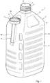
- the container 1 has a body 2 of polymer material for storing fluid products and a pouring spout 3 with a connecting portion 4 and a pouring tube 5 projecting from the connecting portion 4.
- a pouring channel 6 extends through the connecting portion 4 and the pouring tube 5.
- the pouring spout 3 can for instance be of a design as described and shown in applicant's Dutch patent application 2 023 437 .
- the container body 2 has a neck 7 bounding a passage 8 into an internal space 9 of the container body 2 and a fluid storage portion 10, which is located below the neck 7 when the container 1 is in an upright position.
- the neck 7 has a protrusion 11 for engagement to a closure (not shown) and, when the closure has been removed, to the connecting portion 4 of the pouring spout 3 with the pouring channel 6 in fluid communication with the passage 8 of the neck 7.
- the protrusion 11 of the neck forms an external thread for engagement with an internal thread 16 of the connecting portion 4 of the spout 3.
- one or more recesses may be provided on the outer circumference of the neck.
- the fluid storage portion 10 has a wall portion 12 located laterally outwardly relative to the neck 7 and a shoulder portion 13 extending from the neck 7 to the wall portion 12.
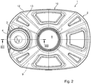
- the container body 2 is of a shape which is basically symmetrical about mutually perpendicular vertical planes through a center line of the neck 7. Such a generally bottle like shape is advantageous for storage, boxing, handling and presentation in a shop.
- a recess 14 is formed in the shoulder portion 13 and, adjacent the shoulder portion 13, in the wall portion 12.
- the recess 14 is open in a horizontal outward direction 15.
- the pouring spout 3 When the pouring spout 3 is in a storage position as shown in the drawings, it is arranged partially in the recess 14 with the pouring tube 5 recessed in the wall portion 12 and the connecting portion 4 located partially above the shoulder portion 13.
- the pouring spout 5 When the container 1 is in the upright position, the pouring spout 5 can be detached from the container body 2 quickly by an upward and/or outward movement in which the pouring tube 5 of the pouring spout 3 is moved axially and/or laterally out of the recess 14.
- the pouring spout 3 can also be gripped easily by an outwardly facing portion of the connecting portion 4, so it can be taken out of the storage position and put back into the storage position particularly easily.
- the connecting portion 4 is at least partially above the shoulder 13 in an empty space to the side of and generally below the neck 7 so it occupies very little or no additional space.
- the pouring spout 3 in the storage position and does not add significantly to the footprint of the container 1.
- the pouring spout 3 in the storage position and does not add significantly to the size of a rectangular box shape 16 in which a container 1 with a given capacity fits.
- the recess 14 is located in an area where wall material is deformed to a relatively small extent during blow molding and therefore has some spare deformability to deform to a shape bounding the recess 14. Accordingly strength and material use are not or only minimally affected by providing the recess 14.
- the pouring spout 3 in the storage position is arranged with the connecting portion 4 partially recessed in the shoulder portion 4.
- the pouring spout 3 in the storage position projects to quite small extent from the container body 2, which is advantageous for avoiding inadvertent dislodgement of the pouring spout 3 during handling or other movements of the container 1, for instance when it is stowed with other items without particular care or when it moves through a luggage or cargo space due to accelerations, decelerations or cornering of a vehicle.
- a container with a recess 14 in the shoulder 13 and, adjacent to the shoulder, in the wall portion 12 of the fluid storage portion 10 is particularly suitable for blow molding the container body 2 from an injection molded preform of a Polyethylenterephthalat (PET) polymer material.
- PET Polyethylenterephthalat
- a PET polymer which may be a PET homolpolymer or a copolymer, such as a copolymer of PET and isophthalic acid or a copolymer of PET, isophthalic acid and a glycol complex (PETG), could at least reduce the occurrence of leakage due to damaged containers, since PET containers that have been stretch blow molded from an injection molded perform are typically stronger than containers blow molded from a tube of other, e.g. polyolefin, material. PET crystallizes at large strains during warm deformation processing. The imparted crystallinity increases its stiffness and strength, improves its dimensional stability, and increases its density.
- PET material While manufacturing such a container from PET material is advantageous in view of its high strength, crystal clear transparency and suitability for recycling, PET material has a relatively small deformability during blow molding.
- the preform is heated (for instance by infrared heaters) until its temperature is above its glass transition temperature. Then, high pressure air is blown into the preform, which causes the portion of the preform inside the mold cavity that is spaced from the inner surface of the mold to be expanded until it contacts the inner surface of the mold.
- the PET material is bi-axially stretched beyond the natural stretch ratio of the polymer (for instance 10 - 12 for a Co-PET, at blowing temperature of 95 °C) and thereby strain hardened, preferably before contacting the inner surface of the mold, due to crystallization and orientation of the polymer material.
- the preform may initially be stretched with a core rod to achieve initial elongation in axial direction.
- the wall material of the preform is less restrained by the inner surface of the mold for controlling deformation up to a predetermined shape corresponding to the shape of the mold cavity than at the recess.
- the wall material has to be able to bulge out to the mold wall on either side of the recess forming portions, within limitations imposed by the strain hardening effect. Since the wall material in the vicinity of the recess is deformed relatively little during blow molding, the portions of the shoulder 13 adjacent the recess 14 can bulge out to the mold wall on either side of the recess forming portions even if the wall material has a relatively small deformability as is typical for PET material.
- the connecting portion 4 has a cylindrical wall having a central axis 17 and the pouring tube 5 extends from the connecting portion 4 in a direction at an angle a diverging relative to the central axis 17 of the connecting portion 4. This facilitates pouring out of liquid out of the container 1 when the pouring spout 3 has been attached to the neck 7.
- the pouring tube 5 diverges from the central axis 17 of the connecting portion 4 in an outward direction.
- the recess 14 allows the recess 14 to have a depth that decreases from the shoulder 13 in a direction away from the neck 7, which in turn is advantageous in that the recess 14 can be obtained with relatively little additional deformation of wall material in the vicinity of the recess 14 as the fluid storage portion 10 of the container body 2 is formed during blow molding.
- an opening 18 of the recess 14 in the shoulder portion 13 and in the wall portion 12 in outward horizontal direction is at least partially of a width w o smaller than an outer width w t of an adjacent portion of the pouring tube 5 in the storage position.
- removing the pouring spout 5 in an outward direction requires that a substantial force is exerted for bending opposite walls of the recess 14 away from each other, so that the pouring spout 5 is normally prevented from inadvertently becoming dislodged from the storage position.
- the pouring spout 5 is also slightly clamped in the recess 14, so that inadvertent dislodgement in an upward direction is also counteracted.
Landscapes
- Engineering & Computer Science (AREA)
- Mechanical Engineering (AREA)
- Containers Having Bodies Formed In One Piece (AREA)
- Devices For Use In Laboratory Experiments (AREA)
Applications Claiming Priority (1)
| Application Number | Priority Date | Filing Date | Title |
|---|---|---|---|
| NL2024149A NL2024149B1 (en) | 2019-11-01 | 2019-11-01 | Container with pouring spout |
Publications (2)
| Publication Number | Publication Date |
|---|---|
| EP3816062A1 true EP3816062A1 (de) | 2021-05-05 |
| EP3816062B1 EP3816062B1 (de) | 2023-03-15 |
Family
ID=69804937
Family Applications (1)
| Application Number | Title | Priority Date | Filing Date |
|---|---|---|---|
| EP20202754.6A Active EP3816062B1 (de) | 2019-11-01 | 2020-10-20 | Behälter mit ausgiesser |
Country Status (4)
| Country | Link |
|---|---|
| EP (1) | EP3816062B1 (de) |
| ES (1) | ES2943535T3 (de) |
| NL (1) | NL2024149B1 (de) |
| PL (1) | PL3816062T3 (de) |
Cited By (2)
| Publication number | Priority date | Publication date | Assignee | Title |
|---|---|---|---|---|
| WO2022015381A1 (en) * | 2020-07-17 | 2022-01-20 | Steen Products, Inc. | Container |
| US11530073B2 (en) | 2020-07-17 | 2022-12-20 | Steen Products, Inc. | Container |
Citations (5)
| Publication number | Priority date | Publication date | Assignee | Title |
|---|---|---|---|---|
| FR2715125A1 (fr) * | 1994-01-17 | 1995-07-21 | Safet Embamet | Bidon en plastique perfectionné. |
| DE202005006134U1 (de) | 2005-04-15 | 2005-06-23 | Dienes Packaging Gmbh | Kanister mit Halterung für eine separate Ausgießhilfe |
| US20060249471A1 (en) * | 2003-09-23 | 2006-11-09 | Vaso Leposavic | Container with cap retainer |
| EP1892192A2 (de) * | 2002-07-31 | 2008-02-27 | General Electric Company | Spender für viskose Flüssigkeit, integriertes Düsenpaket und entsprechendes Verfahren |
| US20110168580A1 (en) * | 2010-01-13 | 2011-07-14 | King Jr L Herbert | Product display container |
-
2019
- 2019-11-01 NL NL2024149A patent/NL2024149B1/en active
-
2020
- 2020-10-20 ES ES20202754T patent/ES2943535T3/es active Active
- 2020-10-20 EP EP20202754.6A patent/EP3816062B1/de active Active
- 2020-10-20 PL PL20202754.6T patent/PL3816062T3/pl unknown
Patent Citations (5)
| Publication number | Priority date | Publication date | Assignee | Title |
|---|---|---|---|---|
| FR2715125A1 (fr) * | 1994-01-17 | 1995-07-21 | Safet Embamet | Bidon en plastique perfectionné. |
| EP1892192A2 (de) * | 2002-07-31 | 2008-02-27 | General Electric Company | Spender für viskose Flüssigkeit, integriertes Düsenpaket und entsprechendes Verfahren |
| US20060249471A1 (en) * | 2003-09-23 | 2006-11-09 | Vaso Leposavic | Container with cap retainer |
| DE202005006134U1 (de) | 2005-04-15 | 2005-06-23 | Dienes Packaging Gmbh | Kanister mit Halterung für eine separate Ausgießhilfe |
| US20110168580A1 (en) * | 2010-01-13 | 2011-07-14 | King Jr L Herbert | Product display container |
Non-Patent Citations (1)
| Title |
|---|
| "Thesis (Ph. D.", 2003, MASSACHUSETTS INSTITUTE OF TECHNOLOGY, DEPT. OF MECHANICAL ENGINEERING |
Cited By (3)
| Publication number | Priority date | Publication date | Assignee | Title |
|---|---|---|---|---|
| WO2022015381A1 (en) * | 2020-07-17 | 2022-01-20 | Steen Products, Inc. | Container |
| US11530073B2 (en) | 2020-07-17 | 2022-12-20 | Steen Products, Inc. | Container |
| US11530125B2 (en) | 2020-07-17 | 2022-12-20 | Steen Products, Inc. | Container |
Also Published As
| Publication number | Publication date |
|---|---|
| NL2024149B1 (en) | 2021-07-19 |
| ES2943535T3 (es) | 2023-06-14 |
| EP3816062B1 (de) | 2023-03-15 |
| PL3816062T3 (pl) | 2023-07-31 |
Similar Documents
| Publication | Publication Date | Title |
|---|---|---|
| US8631963B2 (en) | Side action insert/skeletal stiffening ribs | |
| US10392151B2 (en) | Lightweight container base | |
| EP2319679B1 (de) | System und Verfahren zur Herstellung blasgeformter Behälter mit optimaler Kunststoffverteilung | |
| EP2627493B1 (de) | Streckstangensystem für flüssigkeits- oder hydraulische blasformung und ein verfahren | |
| JP5750002B2 (ja) | プラスチックボトル用プリフォーム及びプラスチックボトル | |
| US9833938B2 (en) | Heat-set container and mold system thereof | |
| KR102350004B1 (ko) | 이너백 용기용 프리폼 및 이중 구조 용기 | |
| US20120000879A1 (en) | Finish horizontal reinforcing rib-ring force | |
| RU2756736C2 (ru) | Нижнее основание контейнера, снабженное двояковогнутым сводом | |
| EP3816062B1 (de) | Behälter mit ausgiesser | |
| EP2792466B1 (de) | Rohling und verfahren zur blasformung eines behälters daraus | |
| CN104812676A (zh) | 底部配有双壁凹拱顶的容器 | |
| EP2150468B1 (de) | Geformter vorformling und behälter mit integriertem ausgiesser | |
| CN109071060B (zh) | 合成树脂制容器 | |
| US20090321386A1 (en) | Lightweight container having mid-body grip | |
| US8505757B2 (en) | Shoulder rib to direct top load force | |
| CA2827073A1 (en) | Vacuum panel with balanced vacuum and pressure response | |
| CA2735814C (en) | Preform for making plastic container | |
| US20080083695A1 (en) | Pinch grip for hot-fillable container | |
| KR20080019572A (ko) | 합성수지제 병체 | |
| JP2001122237A (ja) | 延伸ブロー成形による超薄肉ボトル | |
| WO2011109623A2 (en) | Flexible standing ring for hot-fill container | |
| CA3176292A1 (en) | Multi-serve container with oval cross-section | |
| WO2011156145A1 (en) | Heat sterilizable plastic container | |
| JP2008007147A (ja) | 合成樹脂製の耐圧ボトル |
Legal Events
| Date | Code | Title | Description |
|---|---|---|---|
| PUAI | Public reference made under article 153(3) epc to a published international application that has entered the european phase |
Free format text: ORIGINAL CODE: 0009012 |
|
| STAA | Information on the status of an ep patent application or granted ep patent |
Free format text: STATUS: THE APPLICATION HAS BEEN PUBLISHED |
|
| AK | Designated contracting states |
Kind code of ref document: A1 Designated state(s): AL AT BE BG CH CY CZ DE DK EE ES FI FR GB GR HR HU IE IS IT LI LT LU LV MC MK MT NL NO PL PT RO RS SE SI SK SM TR |
|
| STAA | Information on the status of an ep patent application or granted ep patent |
Free format text: STATUS: REQUEST FOR EXAMINATION WAS MADE |
|
| 17P | Request for examination filed |
Effective date: 20210910 |
|
| RBV | Designated contracting states (corrected) |
Designated state(s): AL AT BE BG CH CY CZ DE DK EE ES FI FR GB GR HR HU IE IS IT LI LT LU LV MC MK MT NL NO PL PT RO RS SE SI SK SM TR |
|
| GRAP | Despatch of communication of intention to grant a patent |
Free format text: ORIGINAL CODE: EPIDOSNIGR1 |
|
| STAA | Information on the status of an ep patent application or granted ep patent |
Free format text: STATUS: GRANT OF PATENT IS INTENDED |
|
| INTG | Intention to grant announced |
Effective date: 20220929 |
|
| GRAS | Grant fee paid |
Free format text: ORIGINAL CODE: EPIDOSNIGR3 |
|
| GRAA | (expected) grant |
Free format text: ORIGINAL CODE: 0009210 |
|
| STAA | Information on the status of an ep patent application or granted ep patent |
Free format text: STATUS: THE PATENT HAS BEEN GRANTED |
|
| AK | Designated contracting states |
Kind code of ref document: B1 Designated state(s): AL AT BE BG CH CY CZ DE DK EE ES FI FR GB GR HR HU IE IS IT LI LT LU LV MC MK MT NL NO PL PT RO RS SE SI SK SM TR |
|
| REG | Reference to a national code |
Ref country code: CH Ref legal event code: EP Ref country code: GB Ref legal event code: FG4D |
|
| REG | Reference to a national code |
Ref country code: DE Ref legal event code: R096 Ref document number: 602020008850 Country of ref document: DE |
|
| REG | Reference to a national code |
Ref country code: IE Ref legal event code: FG4D |
|
| REG | Reference to a national code |
Ref country code: AT Ref legal event code: REF Ref document number: 1553889 Country of ref document: AT Kind code of ref document: T Effective date: 20230415 |
|
| REG | Reference to a national code |
Ref country code: NL Ref legal event code: FP |
|
| P01 | Opt-out of the competence of the unified patent court (upc) registered |
Effective date: 20230508 |
|
| REG | Reference to a national code |
Ref country code: ES Ref legal event code: FG2A Ref document number: 2943535 Country of ref document: ES Kind code of ref document: T3 Effective date: 20230614 |
|
| REG | Reference to a national code |
Ref country code: LT Ref legal event code: MG9D |
|
| PG25 | Lapsed in a contracting state [announced via postgrant information from national office to epo] |
Ref country code: RS Free format text: LAPSE BECAUSE OF FAILURE TO SUBMIT A TRANSLATION OF THE DESCRIPTION OR TO PAY THE FEE WITHIN THE PRESCRIBED TIME-LIMIT Effective date: 20230315 Ref country code: NO Free format text: LAPSE BECAUSE OF FAILURE TO SUBMIT A TRANSLATION OF THE DESCRIPTION OR TO PAY THE FEE WITHIN THE PRESCRIBED TIME-LIMIT Effective date: 20230615 Ref country code: LV Free format text: LAPSE BECAUSE OF FAILURE TO SUBMIT A TRANSLATION OF THE DESCRIPTION OR TO PAY THE FEE WITHIN THE PRESCRIBED TIME-LIMIT Effective date: 20230315 Ref country code: LT Free format text: LAPSE BECAUSE OF FAILURE TO SUBMIT A TRANSLATION OF THE DESCRIPTION OR TO PAY THE FEE WITHIN THE PRESCRIBED TIME-LIMIT Effective date: 20230315 Ref country code: HR Free format text: LAPSE BECAUSE OF FAILURE TO SUBMIT A TRANSLATION OF THE DESCRIPTION OR TO PAY THE FEE WITHIN THE PRESCRIBED TIME-LIMIT Effective date: 20230315 |
|
| REG | Reference to a national code |
Ref country code: AT Ref legal event code: MK05 Ref document number: 1553889 Country of ref document: AT Kind code of ref document: T Effective date: 20230315 |
|
| PG25 | Lapsed in a contracting state [announced via postgrant information from national office to epo] |
Ref country code: SE Free format text: LAPSE BECAUSE OF FAILURE TO SUBMIT A TRANSLATION OF THE DESCRIPTION OR TO PAY THE FEE WITHIN THE PRESCRIBED TIME-LIMIT Effective date: 20230315 Ref country code: GR Free format text: LAPSE BECAUSE OF FAILURE TO SUBMIT A TRANSLATION OF THE DESCRIPTION OR TO PAY THE FEE WITHIN THE PRESCRIBED TIME-LIMIT Effective date: 20230616 Ref country code: FI Free format text: LAPSE BECAUSE OF FAILURE TO SUBMIT A TRANSLATION OF THE DESCRIPTION OR TO PAY THE FEE WITHIN THE PRESCRIBED TIME-LIMIT Effective date: 20230315 |
|
| PG25 | Lapsed in a contracting state [announced via postgrant information from national office to epo] |
Ref country code: SM Free format text: LAPSE BECAUSE OF FAILURE TO SUBMIT A TRANSLATION OF THE DESCRIPTION OR TO PAY THE FEE WITHIN THE PRESCRIBED TIME-LIMIT Effective date: 20230315 Ref country code: RO Free format text: LAPSE BECAUSE OF FAILURE TO SUBMIT A TRANSLATION OF THE DESCRIPTION OR TO PAY THE FEE WITHIN THE PRESCRIBED TIME-LIMIT Effective date: 20230315 Ref country code: PT Free format text: LAPSE BECAUSE OF FAILURE TO SUBMIT A TRANSLATION OF THE DESCRIPTION OR TO PAY THE FEE WITHIN THE PRESCRIBED TIME-LIMIT Effective date: 20230717 Ref country code: EE Free format text: LAPSE BECAUSE OF FAILURE TO SUBMIT A TRANSLATION OF THE DESCRIPTION OR TO PAY THE FEE WITHIN THE PRESCRIBED TIME-LIMIT Effective date: 20230315 Ref country code: CZ Free format text: LAPSE BECAUSE OF FAILURE TO SUBMIT A TRANSLATION OF THE DESCRIPTION OR TO PAY THE FEE WITHIN THE PRESCRIBED TIME-LIMIT Effective date: 20230315 Ref country code: AT Free format text: LAPSE BECAUSE OF FAILURE TO SUBMIT A TRANSLATION OF THE DESCRIPTION OR TO PAY THE FEE WITHIN THE PRESCRIBED TIME-LIMIT Effective date: 20230315 |
|
| PG25 | Lapsed in a contracting state [announced via postgrant information from national office to epo] |
Ref country code: SK Free format text: LAPSE BECAUSE OF FAILURE TO SUBMIT A TRANSLATION OF THE DESCRIPTION OR TO PAY THE FEE WITHIN THE PRESCRIBED TIME-LIMIT Effective date: 20230315 Ref country code: IS Free format text: LAPSE BECAUSE OF FAILURE TO SUBMIT A TRANSLATION OF THE DESCRIPTION OR TO PAY THE FEE WITHIN THE PRESCRIBED TIME-LIMIT Effective date: 20230715 |
|
| REG | Reference to a national code |
Ref country code: DE Ref legal event code: R097 Ref document number: 602020008850 Country of ref document: DE |
|
| PLBE | No opposition filed within time limit |
Free format text: ORIGINAL CODE: 0009261 |
|
| STAA | Information on the status of an ep patent application or granted ep patent |
Free format text: STATUS: NO OPPOSITION FILED WITHIN TIME LIMIT |
|
| PG25 | Lapsed in a contracting state [announced via postgrant information from national office to epo] |
Ref country code: SI Free format text: LAPSE BECAUSE OF FAILURE TO SUBMIT A TRANSLATION OF THE DESCRIPTION OR TO PAY THE FEE WITHIN THE PRESCRIBED TIME-LIMIT Effective date: 20230315 Ref country code: DK Free format text: LAPSE BECAUSE OF FAILURE TO SUBMIT A TRANSLATION OF THE DESCRIPTION OR TO PAY THE FEE WITHIN THE PRESCRIBED TIME-LIMIT Effective date: 20230315 |
|
| 26N | No opposition filed |
Effective date: 20231218 |
|
| PG25 | Lapsed in a contracting state [announced via postgrant information from national office to epo] |
Ref country code: MC Free format text: LAPSE BECAUSE OF FAILURE TO SUBMIT A TRANSLATION OF THE DESCRIPTION OR TO PAY THE FEE WITHIN THE PRESCRIBED TIME-LIMIT Effective date: 20230315 |
|
| REG | Reference to a national code |
Ref country code: CH Ref legal event code: PL |
|
| PG25 | Lapsed in a contracting state [announced via postgrant information from national office to epo] |
Ref country code: CH Free format text: LAPSE BECAUSE OF NON-PAYMENT OF DUE FEES Effective date: 20231031 |
|
| PG25 | Lapsed in a contracting state [announced via postgrant information from national office to epo] |
Ref country code: CH Free format text: LAPSE BECAUSE OF NON-PAYMENT OF DUE FEES Effective date: 20231031 |
|
| PG25 | Lapsed in a contracting state [announced via postgrant information from national office to epo] |
Ref country code: IE Free format text: LAPSE BECAUSE OF NON-PAYMENT OF DUE FEES Effective date: 20231020 |
|
| PG25 | Lapsed in a contracting state [announced via postgrant information from national office to epo] |
Ref country code: IE Free format text: LAPSE BECAUSE OF NON-PAYMENT OF DUE FEES Effective date: 20231020 |
|
| PG25 | Lapsed in a contracting state [announced via postgrant information from national office to epo] |
Ref country code: BG Free format text: LAPSE BECAUSE OF FAILURE TO SUBMIT A TRANSLATION OF THE DESCRIPTION OR TO PAY THE FEE WITHIN THE PRESCRIBED TIME-LIMIT Effective date: 20230315 |
|
| PG25 | Lapsed in a contracting state [announced via postgrant information from national office to epo] |
Ref country code: BG Free format text: LAPSE BECAUSE OF FAILURE TO SUBMIT A TRANSLATION OF THE DESCRIPTION OR TO PAY THE FEE WITHIN THE PRESCRIBED TIME-LIMIT Effective date: 20230315 |
|
| GBPC | Gb: european patent ceased through non-payment of renewal fee |
Effective date: 20241020 |
|
| PG25 | Lapsed in a contracting state [announced via postgrant information from national office to epo] |
Ref country code: GB Free format text: LAPSE BECAUSE OF NON-PAYMENT OF DUE FEES Effective date: 20241020 |
|
| PG25 | Lapsed in a contracting state [announced via postgrant information from national office to epo] |
Ref country code: CY Free format text: LAPSE BECAUSE OF FAILURE TO SUBMIT A TRANSLATION OF THE DESCRIPTION OR TO PAY THE FEE WITHIN THE PRESCRIBED TIME-LIMIT; INVALID AB INITIO Effective date: 20201020 |
|
| PG25 | Lapsed in a contracting state [announced via postgrant information from national office to epo] |
Ref country code: HU Free format text: LAPSE BECAUSE OF FAILURE TO SUBMIT A TRANSLATION OF THE DESCRIPTION OR TO PAY THE FEE WITHIN THE PRESCRIBED TIME-LIMIT; INVALID AB INITIO Effective date: 20201020 |
|
| PGFP | Annual fee paid to national office [announced via postgrant information from national office to epo] |
Ref country code: PL Payment date: 20250922 Year of fee payment: 6 |
|
| PGFP | Annual fee paid to national office [announced via postgrant information from national office to epo] |
Ref country code: NL Payment date: 20251021 Year of fee payment: 6 Ref country code: LU Payment date: 20251022 Year of fee payment: 6 |
|
| PG25 | Lapsed in a contracting state [announced via postgrant information from national office to epo] |
Ref country code: TR Free format text: LAPSE BECAUSE OF FAILURE TO SUBMIT A TRANSLATION OF THE DESCRIPTION OR TO PAY THE FEE WITHIN THE PRESCRIBED TIME-LIMIT Effective date: 20230315 |
|
| PGFP | Annual fee paid to national office [announced via postgrant information from national office to epo] |
Ref country code: DE Payment date: 20251021 Year of fee payment: 6 |
|
| PGFP | Annual fee paid to national office [announced via postgrant information from national office to epo] |
Ref country code: IT Payment date: 20251024 Year of fee payment: 6 |
|
| PGFP | Annual fee paid to national office [announced via postgrant information from national office to epo] |
Ref country code: FR Payment date: 20251030 Year of fee payment: 6 |
|
| PGFP | Annual fee paid to national office [announced via postgrant information from national office to epo] |
Ref country code: BE Payment date: 20251021 Year of fee payment: 6 |
|
| PGFP | Annual fee paid to national office [announced via postgrant information from national office to epo] |
Ref country code: ES Payment date: 20251216 Year of fee payment: 6 |