EP3816367A1 - Support de coffrage - Google Patents
Support de coffrage Download PDFInfo
- Publication number
- EP3816367A1 EP3816367A1 EP19205726.3A EP19205726A EP3816367A1 EP 3816367 A1 EP3816367 A1 EP 3816367A1 EP 19205726 A EP19205726 A EP 19205726A EP 3816367 A1 EP3816367 A1 EP 3816367A1
- Authority
- EP
- European Patent Office
- Prior art keywords
- rotation
- support part
- formwork
- prop
- section
- Prior art date
- Legal status (The legal status is an assumption and is not a legal conclusion. Google has not performed a legal analysis and makes no representation as to the accuracy of the status listed.)
- Pending
Links
Images



Classifications
-
- E—FIXED CONSTRUCTIONS
- E04—BUILDING
- E04G—SCAFFOLDING; FORMS; SHUTTERING; BUILDING IMPLEMENTS OR AIDS, OR THEIR USE; HANDLING BUILDING MATERIALS ON THE SITE; REPAIRING, BREAKING-UP OR OTHER WORK ON EXISTING BUILDINGS
- E04G11/00—Forms, shutterings, or falsework for making walls, floors, ceilings, or roofs
- E04G11/36—Forms, shutterings, or falsework for making walls, floors, ceilings, or roofs for floors, ceilings, or roofs of plane or curved surfaces end formpanels for floor shutterings
- E04G11/48—Supporting structures for shutterings or frames for floors or roofs
- E04G11/50—Girders, beams, or the like as supporting members for forms
- E04G11/54—Girders, beams, or the like as supporting members for forms of extensible type, with or without adjustable supporting shoes, fishplates, or the like
- E04G11/56—Girders, beams, or the like as supporting members for forms of extensible type, with or without adjustable supporting shoes, fishplates, or the like of telescopic type
-
- E—FIXED CONSTRUCTIONS
- E04—BUILDING
- E04G—SCAFFOLDING; FORMS; SHUTTERING; BUILDING IMPLEMENTS OR AIDS, OR THEIR USE; HANDLING BUILDING MATERIALS ON THE SITE; REPAIRING, BREAKING-UP OR OTHER WORK ON EXISTING BUILDINGS
- E04G11/00—Forms, shutterings, or falsework for making walls, floors, ceilings, or roofs
- E04G11/36—Forms, shutterings, or falsework for making walls, floors, ceilings, or roofs for floors, ceilings, or roofs of plane or curved surfaces end formpanels for floor shutterings
- E04G11/48—Supporting structures for shutterings or frames for floors or roofs
-
- E—FIXED CONSTRUCTIONS
- E04—BUILDING
- E04G—SCAFFOLDING; FORMS; SHUTTERING; BUILDING IMPLEMENTS OR AIDS, OR THEIR USE; HANDLING BUILDING MATERIALS ON THE SITE; REPAIRING, BREAKING-UP OR OTHER WORK ON EXISTING BUILDINGS
- E04G25/00—Shores or struts; Chocks
- E04G25/04—Shores or struts; Chocks telescopic
- E04G25/06—Shores or struts; Chocks telescopic with parts held together by positive means
- E04G25/061—Shores or struts; Chocks telescopic with parts held together by positive means by pins
-
- E—FIXED CONSTRUCTIONS
- E04—BUILDING
- E04G—SCAFFOLDING; FORMS; SHUTTERING; BUILDING IMPLEMENTS OR AIDS, OR THEIR USE; HANDLING BUILDING MATERIALS ON THE SITE; REPAIRING, BREAKING-UP OR OTHER WORK ON EXISTING BUILDINGS
- E04G25/00—Shores or struts; Chocks
- E04G25/04—Shores or struts; Chocks telescopic
- E04G25/06—Shores or struts; Chocks telescopic with parts held together by positive means
- E04G25/065—Shores or struts; Chocks telescopic with parts held together by positive means by a threaded nut
-
- F—MECHANICAL ENGINEERING; LIGHTING; HEATING; WEAPONS; BLASTING
- F16—ENGINEERING ELEMENTS AND UNITS; GENERAL MEASURES FOR PRODUCING AND MAINTAINING EFFECTIVE FUNCTIONING OF MACHINES OR INSTALLATIONS; THERMAL INSULATION IN GENERAL
- F16B—DEVICES FOR FASTENING OR SECURING CONSTRUCTIONAL ELEMENTS OR MACHINE PARTS TOGETHER, e.g. NAILS, BOLTS, CIRCLIPS, CLAMPS, CLIPS OR WEDGES; JOINTS OR JOINTING
- F16B7/00—Connections of rods or tubes, e.g. of non-circular section, mutually, including resilient connections
- F16B7/10—Telescoping systems
- F16B7/14—Telescoping systems locking in intermediate non-discrete positions
-
- F—MECHANICAL ENGINEERING; LIGHTING; HEATING; WEAPONS; BLASTING
- F16—ENGINEERING ELEMENTS AND UNITS; GENERAL MEASURES FOR PRODUCING AND MAINTAINING EFFECTIVE FUNCTIONING OF MACHINES OR INSTALLATIONS; THERMAL INSULATION IN GENERAL
- F16B—DEVICES FOR FASTENING OR SECURING CONSTRUCTIONAL ELEMENTS OR MACHINE PARTS TOGETHER, e.g. NAILS, BOLTS, CIRCLIPS, CLAMPS, CLIPS OR WEDGES; JOINTS OR JOINTING
- F16B7/00—Connections of rods or tubes, e.g. of non-circular section, mutually, including resilient connections
- F16B7/18—Connections of rods or tubes, e.g. of non-circular section, mutually, including resilient connections using screw-thread elements
- F16B7/182—Connections of rods or tubes, e.g. of non-circular section, mutually, including resilient connections using screw-thread elements for coaxial connections of two rods or tubes
-
- E—FIXED CONSTRUCTIONS
- E04—BUILDING
- E04G—SCAFFOLDING; FORMS; SHUTTERING; BUILDING IMPLEMENTS OR AIDS, OR THEIR USE; HANDLING BUILDING MATERIALS ON THE SITE; REPAIRING, BREAKING-UP OR OTHER WORK ON EXISTING BUILDINGS
- E04G25/00—Shores or struts; Chocks
- E04G25/04—Shores or struts; Chocks telescopic
- E04G2025/042—Shores or struts; Chocks telescopic with devices to avoid accidental disengagement of the telescopic elements, e.g. during transport
-
- E—FIXED CONSTRUCTIONS
- E21—EARTH OR ROCK DRILLING; MINING
- E21D—SHAFTS; TUNNELS; GALLERIES; LARGE UNDERGROUND CHAMBERS
- E21D15/00—Props; Chocks, e.g. made of flexible containers filled with backfilling material
- E21D15/14—Telescopic props
- E21D15/16—Telescopic props with parts held together by positive means, with or without relative sliding movement when the prop is subject to excessive pressure
- E21D15/24—Telescopic props with parts held together by positive means, with or without relative sliding movement when the prop is subject to excessive pressure with axial screw-and-nut, rack-and-worm, or like mechanism
Definitions
- the invention relates to a formwork prop with an outer pillar part and a telescopic inner pillar part, the inner pillar part having an anti-rotation section and the outer pillar part having an anti-rotation area with a first inner contour Support part cooperates that a rotation of the inner support part about its longitudinal axis relative to the outer support part is blocked.
- the invention also relates to a ceiling formwork for producing a ceiling element with at least one formwork panel and at least one formwork support.
- Formwork props of the type mentioned are used on construction sites for the production of ceilings.
- the formwork props are set up using a formwork plan and aligned with one another.
- the prop heads should be aligned parallel to the head ends of the formwork props in order to enable the placement of transverse and longitudinal girders as well as formwork panels in the next work step.
- the DE 201 22 664 U1 shows a formwork prop.
- the formwork prop has an outer and an inner prop part which can be pulled out to extend the formwork prop.
- the outer and inner support parts each have locking holes through which a locking bolt can be passed.
- the support parts can be rotated with respect to one another during telescoping.
- Another formwork prop is from the DE 94 21 029 U1 known.
- This formwork prop also has an outer and an inner prop part located therein, on both Support parts are provided for locking hole pairs with opposite locking holes through which a locking bolt can be passed.
- the two support parts can be rotated during telescoping.
- formwork props with anti-rotation locks have a comparatively complex structure compared to formwork props without anti-rotation locks, which makes production and handling more difficult and increases weight.
- formwork props that are easy to manufacture, are easy to operate, have a low susceptibility to errors, can withstand high loads and are low in weight would be desirable.
- the object of the present invention to at least reduce or completely eliminate the disadvantages of the prior art.
- the outer support part has a guide area with a second inner contour different from the first inner contour for guiding the inner support part.
- the telescoping of the formwork prop is advantageously facilitated by the guidance of the inner support part in the guide area.
- the guide area of the outer support part can expediently encompass the entire outer circumference of the inner support part.
- the second inner contour can be adapted to the outer contour of the inner support part and essentially correspond to this in terms of shape and size.
- the second inner contour can differ from the first inner contour, for example in terms of size and / or shape.
- the second inner contour is preferably tapered compared to the first inner contour.
- the formwork prop according to the invention prevents twisting of the inner support part relative to the outer support part, preferably by means of a positive fit, by the interaction of the anti-rotation section and the anti-rotation protection area.
- the inner and outer support parts of the formwork prop according to the invention are always oriented in the same way with respect to one another and therefore always have the same rotational position with respect to one another when used as intended.
- the formwork prop according to the invention is therefore secured against rotation.
- the prop parts can be locked in place more easily and, above all, more quickly, which reduces the time required to set up the formwork props.
- the anti-rotation area of the outer support part is that area which, by interacting with the anti-rotation section of the inner support part, blocks rotation of the inner support part with respect to the outer support part, but at the same time a translational displacement of the inner support part relative to the outer support part in the longitudinal direction of the formwork support allowed.
- the anti-rotation area preferably adjoins the guide area and merges into it.
- the guide area can in particular be arranged in an upper end area of the outer support part.
- directions such as “up”, “down” and “outside” relate to the intended use of the formwork prop, in which the formwork prop stands on a contact surface and the “top” longitudinal and cross members can be placed on the formwork prop.
- “Inward” means towards the longitudinal axis.
- the anti-rotation area of the outer support part has a first inner contour that is different from the second inner contour.
- the first inner contour can have a polygonal shape, for example. It can also be provided, for example, that the outer support part has an inwardly protruding anti-rotation element in the anti-rotation area, which cooperates with the anti-rotation section of the inner support part.
- the inner contour is essentially the same in the entire anti-rotation area.
- the inner contour is also preferably essentially the same in the entire guide area, with the exception of a possible transition area to the anti-rotation area. However, this does not necessarily have to be the case. It is important that the guide area has a second inner contour that is different from the first inner contour.
- the first inner contour is intended to block rotation of the inner support part, while the second inner contour enables the inner support part to be guided.
- the "inner contour” is to be understood as the inner boundary of a cross section. Accordingly, an outer contour designates the outer edge of a cross section.
- the first inner contour accordingly designates the inner edge of a cross section of the outer support part in the anti-rotation area, possibly with any anti-rotation elements.
- the second inner contour accordingly designates the inner edge of a cross section of the outer support part in the guide area.
- the inner support part is preferably designed to be hollow.
- the inner support part can be made in one piece, optionally with joint connections, be trained.
- the inner and outer support parts are preferably made of metal, more preferably of steel. It is particularly preferred if the inner and outer support parts are made of different materials. It can also be provided that the outer support part has an area with an essentially circular inner contour and / or outer contour at the end opposite the guide area. This makes it easier to weld on a plate, in particular a base plate.
- the inner support part has the anti-rotation section and a pull-out section.
- the anti-rotation section can be connected to the pull-out section and, in particular, merge into it.
- the pull-out section and the anti-rotation section can be in one piece.
- the pull-out section is that section that can be pulled out of the outer support part when telescoping, thereby lengthening the formwork support.
- the anti-rotation section and part of the pull-out section can also remain in the outer support part in the telescoped state for the purpose of stability and security.
- the anti-rotation section extends essentially over the entire length of the inner support part.
- the second inner contour essentially corresponds to the outer contour of the inner support part, possibly the outer contour of the pull-out section of the inner support part.
- the inner support part or the pull-out section can essentially have a circular outer contour and the second inner contour accordingly also have a circular shape.
- the guide area can also have an outer contour which corresponds in shape to the second inner contour.
- the anti-rotation area can also have an outer contour that corresponds to the shape of the first inner contour.
- the second inner contour has a circular shape and is preferably tapered compared to the first inner contour.
- Tapered in this context means that of the second inner contour limited area is smaller than the area bounded by the first inner contour. It is advantageous if the shape of the second inner contour corresponds to the shape of the outer contour of the inner support part, in particular of a pull-out section.
- the second inner contour which is tapered with respect to the first inner contour, can advantageously also prevent foreign bodies from entering the interior of the formwork prop.
- the anti-rotation area and the guide area can be designed in one piece and, in particular, merge into one another in a stepless manner.
- the anti-rotation area and the guide area can have been produced from a single workpiece, possibly with joint connections. This can be achieved in particular by reshaping a semi-finished product. Accordingly, the anti-rotation area and the guide area are connected to one another without a joint.
- stepless means that a transition area between the guide area and the anti-rotation area is free of projections, gradations and offsets, among other things.
- the anti-rotation section has at least one anti-rotation indentation and the outer support part in the anti-rotation area has at least one anti-rotation indentation, the anti-rotation indentation being displaceable when telescoping the inner support part along the anti-rotation indentation and a rotation of the inner support part around its longitudinal axis blocked.
- the anti-rotation indentation thus interacts with the anti-rotation indentation of the outer support part in such a way that rotations about the longitudinal axis are blocked, but translational movements in the longitudinal direction of the formwork support are made possible.
- the anti-rotation indentation can slide in particular in the anti-rotation indentation.
- the anti-rotation bulge preferably projects radially outward from the inner support part.
- the anti-rotation bulge can be, among other things, a pin, a corner, an edge or a curvature.
- the anti-rotation indentation is preferably elongated and oriented in the direction of the longitudinal axis of the formwork prop.
- the anti-rotation indentation can be located on the inside of the outer support part.
- the inside of the outer support part is formed by the inner wall of the outer support part.
- the indentation preventing rotation is preferably arched outwards and can be formed, for example, by a groove or an edge.
- the number of indentations preventing rotation is preferably at least as high as the number of indentations preventing rotation.
- the anti-rotation indentation slides in the longitudinal direction of the formwork support in the anti-rotation indentation.
- the interaction of the anti-rotation indentation with the anti-rotation indentation preferably by means of a form fit, blocks rotation of the inner and outer support parts with respect to one another.
- an anti-rotation indentation can be provided in the anti-rotation section and an anti-rotation indentation in the anti-rotation area.
- the anti-rotation indentation and the anti-rotation indentation are arched inward and the indentation protection against rotation slides along the indentation protection against rotation when telescoping.
- the first inner contour has an n-cornered, preferably a regular n-cornered, in particular a hexagonal or octagonal shape, and the indentations preventing rotation, viewed in cross section, are formed through the n corners of the first inner contour.
- the inner contour can be the same in the entire anti-rotation area.
- the outer support part can advantageously be approximated to a circular shape due to the n-angular shape, which has a favorable effect on the stability of the entire formwork support.
- "n" is a natural number and denotes the number of corners. The corners form the anti-rotation indentations which are delimited by the edges connecting the corners.
- the first inner contour designates the inner contour of the cross section of the outer support part, that is to say the contour of the inside or inner wall of the outer support part.
- the shape of the outer wall / outer contour can essentially correspond to the shape of the inner wall / inner contour.
- the anti-rotation section of the inner support part has an n-angular, preferably a regular n-angular, in particular an essentially square, outer contour and the n corners of the outer contour, viewed in cross-section, each form an anti-rotation indentation, the corners preferably being rounded are.
- "n” in turn denotes a natural number and denotes the number of corners.
- the number of corners of the anti-rotation section can, however, differ from the number of corners of the anti-rotation area. In this embodiment there are thus n indentations preventing rotation, wherein at least one corresponding indentation preventing rotation can be provided for each indentation preventing rotation.
- the outer contour of the anti-rotation section denotes the external contour of the cross-section of the anti-rotation section.
- the outer contour can be the same in the entire anti-rotation section.
- the outer support part preferably has a length of at least 80 cm, in particular at least 80.8 cm, 135.6 cm, 160.6 cm, 185.6 cm, 210.6 cm, 238.5 cm, 285.6 cm or 370 , 6 cm.
- the inner support part preferably has a length of at least 90 cm, in particular at least 90.9 cm, 145.7 cm, 170.7 cm, 195.7 cm, 220.7 cm, 245.7 cm, 295.7 cm or 380 cm , 7 cm.
- the anti-rotation section is provided at an end region of the inner support part.
- the anti-rotation section can form the closure, that is to say the end, of the inner support part.
- the end region of the inner support part on which the anti-rotation section is provided is that which remains in the outer support part during telescoping and is not pulled out.
- the anti-rotation area extends over the distance covered by the anti-rotation area between a fully telescoped area and a fully retracted position of the inner support member.
- the fully inserted position is that position in which the inner support part is pushed into the outer support part the furthest, in particular essentially completely.
- the fully telescoped position is a position in which the inner support part is pulled out of the outer support part to extend the formwork support, but is still at least partially in the outer support part so as not to impair the function of the formwork support.
- the largest outside diameter of the anti-rotation section corresponds essentially to the largest internal diameter of the anti-rotation area.
- the outer diameter of the anti-rotation section relates to its cross section.
- the largest outside diameter usually corresponds to the longest diagonal. If, for example, the anti-rotation section has a square outer contour, the largest outer diameter is the diagonal of the square. In the case of an n-gon, the largest diameter would be the longest diagonal between two corners.
- the largest inner diameter of the anti-rotation area which relates to the cross section of the outer support part, more precisely, its inner side or the first inner contour.
- the inner support part can have an extension section and the guide region can have an inner diameter which essentially corresponds to the largest outer diameter of the extension section.
- the largest outside diameter of the anti-rotation section is expediently larger than the largest outside diameter of the pull-out section.
- the anti-rotation section can therefore not be pushed through the guide area.
- the diameters in turn relate to the cross-sections of the respective elements.
- the guide area blocks the anti-rotation section from being pulled out.
- the guide area preferably has an essentially circular inner contour.
- an extension section can have an essentially circular outer contour in order to simplify the production of the inner support part and to increase the stability of the formwork support as a whole.
- the outer contour of the pull-out section designates the outer contour of the cross-section of the pull-out section.
- the outer contour of the pull-out section is preferably the same along its entire longitudinal extent.
- the pull-out section is formed by a round tube or a hollow cylinder. Alternatively, however, full cylinders can also be provided.
- the inner support part has at least one securing hole and the outer support part, preferably in the guide area, has at least one holding recess, in particular an elongated holding hole, the formwork prop being in a telescoped position in which the securing hole and the at least one holding recess are superimposed lie that a securing bolt can be passed through the securing hole and the retaining recess at the same time.
- a plurality of securing holes are arranged at regular intervals along a straight line along the longitudinal direction of the inner support part. If a pull-out section is provided, the securing hole is preferably provided therein.
- the pull-out section is preferably designed as a tube which has several pairs of holes each with two opposing securing holes through which the securing bolt can be passed transversely to the longitudinal direction of the inner support part from one side of the tube to the other.
- the outer support part preferably also has a pair of holes with two holding holes, in particular elongated holding holes, arranged on opposite longitudinal sides of the outer support part.
- pairs of holes on the inner support part they are advantageously oriented along the longitudinal axis of the inner support part in such a way that they slide past the elongated retaining holes when the formwork support is telescoped, so that the securing bolt can be passed through the inner and outer support part at the same time.
- the outer prop part can be provided with a securing bolt in the region of the at least one holding recess, which can be passed through the at least one holding recess and the at least one securing hole.
- the securing bolt preferably has two opposing U-shaped sections with different curve radii.
- the U-shaped section with the smaller curve radius has a securing leg, which can be passed through the at least one holding recess and the at least one securing hole and thus locks the circuit support. With the U-shaped section with the larger curve radius, an unintentional removal of the securing bolt from the formwork prop can be prevented.
- the outer support part has a pair of elongated holding holes, the securing bolt can be displaced therein in the longitudinal direction of the formwork support.
- the outer prop part can have an external thread with a nut in one end area.
- the external thread is preferably located in the guide area.
- the mother is a so-called union nut. If at least a region of the elongated holding hole is arranged within the external thread, a locking bolt that can be displaced therein can be displaced in the longitudinal direction of the formwork support by turning the nut.
- the securing bolt is inserted into the elongated holding hole and rests on the nut.
- the nut can have a securing element that blocks rotation of the nut.
- the object according to the invention is also achieved by a ceiling formwork of the type mentioned in the introduction, in which the at least one formwork prop is designed as described above.
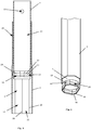
- Fig. 1 shows a formwork prop 1 according to the invention with an outer prop part 2 and an inner prop part 3 arranged therein.
- the inner prop part 3 can be pulled out of the outer prop part 2, ie telescoped.
- the formwork prop 1 can be brought from a fully retracted position into a fully telescoped position.
- the outer support part 2 has an anti-rotation area 4 with an octagonal outer contour and, in an upper end area 5, a guide area 6 with an essentially circular outer contour for guiding the inner support part 3.
- the outer contour of the guide area 6 is opposite to the outer contour of the anti-rotation area 4 tapered and has an external thread 7.
- Plates 8, namely a top plate 9 and a base plate 10, are located at both ends of the formwork prop 1.
- the base plate 10 is connected to a lower end of the outer prop part 2 opposite the guide area 6.
- the head plate 9 is connected to an end of the inner support part 3 protruding from the guide area 6.
- essentially the entire guide region 6 is surrounded on the outside by the external thread 7.
- the external thread 7 can be milled or stamped, for example.
- the guide area 6 with the essentially circular outer contour merges into the anti-rotation area 4 with that of the octagonal outer contour, preferably without a joint connection and in particular steplessly.
- the guide area 6 and the anti-rotation area 4 can in particular have been produced in one piece, ie from a single workpiece. It can be seen that the guide area 6 has a reduced outer diameter compared to the anti-rotation area 4.
- the transition area 11 between the anti-rotation area 4 and the guide area 6 is conically converging.
- a holding recess 40 in the form of an elongated holding hole 12 is provided in the guide region 6, within the external thread 7.
- a further, similar elongated holding hole 12 is provided (not visible).
- the two elongated holding holes 12 together form a pair of elongated holding holes.
- the inner prop part 3 has several securing holes 13. Two securing holes 13 located on opposite sides of the inner support part 3 in turn form a pair of holes. A plurality of such pairs of holes are arranged one below the other along a straight line on the inner support part 3.
- the formwork prop 1 With the help of the securing holes 13, the elongated holding holes 12 and a securing bolt (not shown), it is possible to lock the formwork prop 1 in a telescoped position, but displacements of the securing bolt within the elongated holding holes 11 are possible.
- the formwork prop 1 is brought into a position in which the elongated holding holes 12 lie over a pair of holes made up of two securing holes 13 and thus the securing bolt can be passed through the elongated retaining holes 12 and securing holes 13.
- a union nut 31 (see Fig. 5 ) be provided on which the securing bolt can rest and which has an internal thread that engages in the external thread 7. By turning the union nut 31, the position of the securing bolt in the elongated retaining holes 12 can be changed. The locking procedure is described below Fig. 5 explained.
- Fig. 3 shows part of the formwork prop 1 in longitudinal section. It can be seen here that the inner support part 3 in the embodiment shown has an anti-rotation section 14 and a pull-out section 15.
- the anti-rotation section 14 is provided in an end region 16 of the inner support part 3.
- the pull-out section 15 is formed by a hollow round tube and accordingly has an essentially circular outer contour over its entire longitudinal extent.
- the pull-out section 15 is that section which can be passed through the guide area 6 and thus extends the formwork prop 3 when telescoping.
- a part of the pull-out section 15 will always be covered by the guide area 6, since the anti-rotation section 14 cannot be passed through the guide area 6 due to its size.
- the anti-rotation area 4 has a first inner contour 17 and the guide area 6 has a second inner contour 18 different from the first outer contour 17 (covered by the inner support part 2), the second inner contour 18 preferably tapering compared to the first inner contour 17, i.e. smaller , is.
- the guide area 6 thus has a smaller inner end diameter than the anti-rotation area 4.
- the inner contour is the same in the entire guide area 6 and in the entire anti-rotation area 4. However, this does not necessarily have to be the case. It is important that the guide area 6 has a second inner contour 17 that is different from the first inner contour 17.
- the first inner contour 17 is intended to block rotation of the inner support part while the second inner contour 18 enables the inner support part 3 to be guided.
- the first inner contour 17 of the anti-rotation area 4, like its outer contour, has an octagonal shape.
- the second inner contour 18 of the guide region 6, like its outer contour, has an essentially circular shape.
- the inside diameter of the guide area 6 corresponds essentially to the largest outside diameter of the pull-out section 15, it being possible for a slight play to be provided between the pull-out section 15 and the guide area 6.
- the anti-rotation section 14 is designed to block a rotation of the inner support part 3 with respect to the outer support part 2, but allow translational displacements of the inner support part 3 with respect to the outer support part 2 in the longitudinal direction of the formwork support 1.
- the anti-rotation section 14 has several, in the exemplary embodiment shown, four, anti-rotation bulges 19.
- the anti-rotation indentations 19 slide in elongated anti-rotation indentations 20 on an inner side 21 of the outer support part 2 in the anti-rotation area 4, the anti-rotation indentations 20 being oriented in the longitudinal direction of the formwork prop 1.
- the inner side 21 is formed by the inner wall of the outer support part 2.
- the outer contour of the anti-rotation section 14 has the shape of a square with rounded corners 22, the corners 22 forming the anti-rotation bulges 19.
- the largest diameter of the anti-rotation section 14, in the illustrated case the diagonal of the square of the outer contour, is greater than the diameter of the cross section of the pull-out section 15.
- the outer support part 2 in the anti-rotation section 4 has not only a regular octagonal outer contour, but also a regular octagonal first inner contour 17.
- the Anti-rotation indentations 19 slide in the longitudinal direction in the anti-rotation indentations 20, which, with the exception of the guide region 6, extend essentially over the entire outer support part 2.
- the anti-rotation section 14 is dimensioned in such a way that the anti-rotation bulges 19, viewed in cross section, are blocked by the edges 24 connecting the corners 23 of the outer support part 2 and forming the corners 23 when the inner support part 3 is rotated.
- the largest outer diameter of the anti-rotation section 14 advantageously corresponds essentially to the largest internal diameter of the anti-rotation area 4 of the outer support part 2.
- the corners 22 of the anti-rotation section 14 therefore lie in the corners 23 of the outer support part 2 and are secured against twisting by the edges 24.
- the anti-rotation indentations 20 extend from the end of the outer support part 2 opposite the guide area 6 to the guide area 6.
- the guide area 6 or the second inner contour 18 has a smaller inner diameter than the largest outer diameter of the anti-rotation section 14.
- the base plate 10 prevents the inner prop part 3 from being pulled out.
- a securing bolt 25 is provided.
- the securing bolt 25 shown has two opposing U-shaped sections 26, 27 with different curve radii.
- the U-shaped section 26 with the smaller curve radius has a securing section 28, while the U-shaped section 27 with the larger curve radius has a gripping section 29.
- a leg 30 of the securing section 28 is designed to be passed through the elongated holding holes 12 and the securing holes 13 and to lock the formwork prop 1. This leg 30 of the securing section 28 thus forms the "actual" securing bolt.
- the safety bolt 25 is displaceable in the longitudinal direction in the elongated holding holes 12.
- a union nut 31 can be provided.
- the union nut 31 has an internal thread (not shown) and is arranged on the external thread 7 and can be moved up and down in the longitudinal direction of the formwork prop 1 by twisting it.
- the securing bolt 25 When the securing bolt 25 is inserted into the elongated retaining holes 12 which are arranged in the external thread 7, it can bear on the union nut 31.
- the securing bolt 25 By turning the union nut 31, the securing bolt 25 is displaced in the longitudinal direction of the elongated holes 12.
- the formwork prop 1 is loaded, the force is transmitted from the inner prop part 3 via the securing bolt 25 and the union nut 31 to the outer prop part 2.
- it In order to fix the union nut 31, it can have a securing element 32 which, when activated, prevents the union nut 31 from rotating.
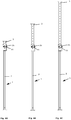
- Figures 6A-C show the formwork prop 1 in different positions, with in Figure 6A the inner support part 3 is pushed the furthest into the outer support part 2.
- the formwork prop 1 could be pushed in even further by turning the union nut 31 or removing the securing bolt 25.
- Figure 6B shows a more extended position of the formwork prop 1.
- Figure 6C shows an even more extended position. Another pulling out would be in accordance with the position Figure 6C no longer possible, since the anti-rotation section 14 is already in contact with the guide area 6.
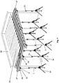
- Fig. 7 shows a ceiling formwork 33 according to the invention with a large number of similar formwork props 1.
- the formwork props 1 are arranged in parallel rows and each have a foldable tripod 34 in the lower area for stabilization and alignment.
- brackets 35 are provided, which secure the longitudinal beams 36 in the form of I-beams.
- Cross members 37 load on the longitudinal members 36 at right angles, so that the load of the concrete (not shown) to be poured later is carried evenly.
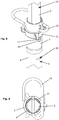
- Fig. 8 shows an alternative embodiment of the formwork prop 1.
- the thread 7 is not shown.
- the inner support part 3 is formed by an n-cornered tube.
- the anti-rotation section 14 of the inner support part 3 extends in this embodiment essentially over the entire length of the inner support part 3.
- the anti-rotation area 4 of the outer support part 2 has an anti-rotation element 39 in the form of an indentation which protrudes inward from the outer support part 2.
- the anti-rotation element 39 interacts with the anti-rotation section 14 of the inner support part 3 in such a way that a rotation of the inner support part 3 during telescopic copying is blocked by positive locking.
- the first inner contour 17 is defined here by the inner wall of the outer support part 2 and the anti-rotation elements 39 and differs from the second inner contour 18 of the guide area.
- the second inner contour 18 is essentially circular.
- Fig. 9 shows the formwork prop 1 in the alternative embodiment in a view from above.
- Fig. 10 shows a longitudinal section of the embodiment according to FIG Fig. 8 .
Landscapes
- Engineering & Computer Science (AREA)
- Architecture (AREA)
- Mechanical Engineering (AREA)
- Civil Engineering (AREA)
- Structural Engineering (AREA)
- General Engineering & Computer Science (AREA)
- Forms Removed On Construction Sites Or Auxiliary Members Thereof (AREA)
Priority Applications (3)
| Application Number | Priority Date | Filing Date | Title |
|---|---|---|---|
| EP19205726.3A EP3816367A1 (fr) | 2019-10-28 | 2019-10-28 | Support de coffrage |
| US17/082,980 US11319714B2 (en) | 2019-10-28 | 2020-10-28 | Telescoping formwork support with twist-proof region |
| CA3097575A CA3097575A1 (en) | 2019-10-28 | 2020-10-28 | Formwork support |
Applications Claiming Priority (1)
| Application Number | Priority Date | Filing Date | Title |
|---|---|---|---|
| EP19205726.3A EP3816367A1 (fr) | 2019-10-28 | 2019-10-28 | Support de coffrage |
Publications (1)
| Publication Number | Publication Date |
|---|---|
| EP3816367A1 true EP3816367A1 (fr) | 2021-05-05 |
Family
ID=68387161
Family Applications (1)
| Application Number | Title | Priority Date | Filing Date |
|---|---|---|---|
| EP19205726.3A Pending EP3816367A1 (fr) | 2019-10-28 | 2019-10-28 | Support de coffrage |
Country Status (3)
| Country | Link |
|---|---|
| US (1) | US11319714B2 (fr) |
| EP (1) | EP3816367A1 (fr) |
| CA (1) | CA3097575A1 (fr) |
Cited By (3)
| Publication number | Priority date | Publication date | Assignee | Title |
|---|---|---|---|---|
| DE102021202378A1 (de) | 2021-03-11 | 2022-09-15 | Peri Se | Verfahren zur Herstellung eines Innenrohres für eine Stützvorrichtung sowie Stützvorrichtung mit einem solchen Innenrohr |
| DE102021211507A1 (de) | 2021-10-12 | 2023-04-13 | Doka Gmbh | Stiel |
| DE102021211506A1 (de) | 2021-10-12 | 2023-04-13 | Doka Gmbh | Stiel |
Families Citing this family (4)
| Publication number | Priority date | Publication date | Assignee | Title |
|---|---|---|---|---|
| USD1029445S1 (en) * | 2022-07-15 | 2024-05-28 | Shenzhen Far-reaching Development Co., Ltd. | Support leg |
| USD1035210S1 (en) * | 2022-07-15 | 2024-07-09 | Shenzhen Far-reaching Development Co., Ltd. | Support leg |
| TWI854867B (zh) * | 2023-10-25 | 2024-09-01 | 龍慶工業有限公司 | 能夠結合模板支撐柱的壓條定位裝置 |
| PL449436A1 (pl) * | 2024-08-01 | 2026-02-02 | Sztobryn Grzegorz Pionart | Podpora stropowa |
Citations (8)
| Publication number | Priority date | Publication date | Assignee | Title |
|---|---|---|---|---|
| WO1992013156A1 (fr) * | 1991-01-28 | 1992-08-06 | Leeuw Petrus J L De | Element de support pour la construction |
| DE9421029U1 (de) | 1994-01-08 | 1995-03-09 | Dingler, Gerhard, 72221 Haiterbach | Stütze |
| EP1195479A2 (fr) * | 2000-10-03 | 2002-04-10 | ULMA C y E, S. COOP. | Etai de construction avec système de sécurité |
| DE20122664U1 (de) | 2001-07-04 | 2007-02-22 | Doka Industrie Gmbh | Rohr einer höhenverstellbaren Stütze sowie höhenverstellbare Stütze |
| KR20110039998A (ko) * | 2009-10-13 | 2011-04-20 | (주)거혁산업 | 서포터의 드럽장치 |
| DE102012211384A1 (de) | 2012-06-29 | 2014-01-02 | Hofin Gmbh | Stütze für Betonierungsschalungen |
| EP3356618A1 (fr) * | 2015-10-01 | 2018-08-08 | DOKA GmbH | Étai |
| EP3438376A1 (fr) * | 2017-07-31 | 2019-02-06 | DOKA GmbH | Appui de coffrage |
Family Cites Families (11)
| Publication number | Priority date | Publication date | Assignee | Title |
|---|---|---|---|---|
| US5314161A (en) * | 1992-05-29 | 1994-05-24 | Bochumer Eisenhutte Heintzmann Gmbh & Co. Kg | Mine prop |
| DE4329910A1 (de) * | 1993-09-04 | 1995-03-09 | Mueller & Baum | Höhenverstellbare Stütze für eine Deckenschalung |
| DE10132253B4 (de) * | 2001-07-04 | 2005-10-27 | Doka Industrie Gmbh | Außen- oder Ständerrohr einer axial verstellbaren Vorrichtung sowie höhenverstellbare Stütze |
| US7165361B2 (en) * | 2003-04-24 | 2007-01-23 | Peter Vanagan | Building construction shores |
| US20100005735A1 (en) * | 2004-08-27 | 2010-01-14 | Gillespie Enterprises Inc. | Telescoping shoring post with gross adjustment capacity |
| PL1975341T3 (pl) * | 2007-03-29 | 2011-12-30 | Ulma C Y E S Coop | Rozpórka z mechanizmem demontażowym |
| KR101243416B1 (ko) | 2009-07-07 | 2013-03-13 | (주)엘지하우시스 | 단열성능 개선을 위한 알루미늄 창호 |
| US20120042495A1 (en) * | 2010-08-23 | 2012-02-23 | Bacon David L | Shoring post with quick release feature |
| WO2012027356A1 (fr) * | 2010-08-23 | 2012-03-01 | Titan Formwork Systems, Llc | Poteau d'étayage doté d'un support de poutre complémentaire |
| KR20180107404A (ko) * | 2017-03-20 | 2018-10-02 | 백희정 | 2중 프롭헤드가 구비된 서포터 및 그를 이용한 시공방법 |
| DE102018125702A1 (de) * | 2018-10-17 | 2020-04-23 | Wilhelm Layher Verwaltungs-Gmbh | Stütze |
-
2019
- 2019-10-28 EP EP19205726.3A patent/EP3816367A1/fr active Pending
-
2020
- 2020-10-28 CA CA3097575A patent/CA3097575A1/en active Pending
- 2020-10-28 US US17/082,980 patent/US11319714B2/en active Active
Patent Citations (9)
| Publication number | Priority date | Publication date | Assignee | Title |
|---|---|---|---|---|
| WO1992013156A1 (fr) * | 1991-01-28 | 1992-08-06 | Leeuw Petrus J L De | Element de support pour la construction |
| DE9421029U1 (de) | 1994-01-08 | 1995-03-09 | Dingler, Gerhard, 72221 Haiterbach | Stütze |
| EP1195479A2 (fr) * | 2000-10-03 | 2002-04-10 | ULMA C y E, S. COOP. | Etai de construction avec système de sécurité |
| DE20122664U1 (de) | 2001-07-04 | 2007-02-22 | Doka Industrie Gmbh | Rohr einer höhenverstellbaren Stütze sowie höhenverstellbare Stütze |
| KR20110039998A (ko) * | 2009-10-13 | 2011-04-20 | (주)거혁산업 | 서포터의 드럽장치 |
| DE102012211384A1 (de) | 2012-06-29 | 2014-01-02 | Hofin Gmbh | Stütze für Betonierungsschalungen |
| EP3356618A1 (fr) * | 2015-10-01 | 2018-08-08 | DOKA GmbH | Étai |
| EP3356618B1 (fr) * | 2015-10-01 | 2022-04-27 | DOKA GmbH | Étai |
| EP3438376A1 (fr) * | 2017-07-31 | 2019-02-06 | DOKA GmbH | Appui de coffrage |
Cited By (3)
| Publication number | Priority date | Publication date | Assignee | Title |
|---|---|---|---|---|
| DE102021202378A1 (de) | 2021-03-11 | 2022-09-15 | Peri Se | Verfahren zur Herstellung eines Innenrohres für eine Stützvorrichtung sowie Stützvorrichtung mit einem solchen Innenrohr |
| DE102021211507A1 (de) | 2021-10-12 | 2023-04-13 | Doka Gmbh | Stiel |
| DE102021211506A1 (de) | 2021-10-12 | 2023-04-13 | Doka Gmbh | Stiel |
Also Published As
| Publication number | Publication date |
|---|---|
| CA3097575A1 (en) | 2021-04-28 |
| US20210123250A1 (en) | 2021-04-29 |
| US11319714B2 (en) | 2022-05-03 |
Similar Documents
| Publication | Publication Date | Title |
|---|---|---|
| DE69105034T2 (de) | Stahlrohrstütze für Bauschalungen. | |
| EP4056785B1 (fr) | Dispositif d'appui, élément d'appui du plafond, système de coffrage du plafond et procédé de décoffrage d'un panneau de coffrage du plafond | |
| EP2513391B1 (fr) | Étai télescopique pour le secteur de la construction | |
| EP3697983A1 (fr) | Étai destiné à étayer une zone de construction | |
| DE102012212603A1 (de) | Arretiervorrichtung mit Wandschalungsbefestigungseinrichtung und Verfahren | |
| DE102012211384A1 (de) | Stütze für Betonierungsschalungen | |
| DE202014002813U1 (de) | Temporäre Wandstütze | |
| DE2040328B2 (de) | Fahrbare Rauminnenschalung für Beton und Stahlbetonbauten | |
| EP4063588A1 (fr) | Composant de liaison | |
| EP0694659B1 (fr) | Echafaudage | |
| DE102017007131A1 (de) | Stahlrohrstütze und Stahlrohrstützenanordnung | |
| EP0625622A1 (fr) | Etai télescopique | |
| DE102018125702A1 (de) | Stütze | |
| DE202019102265U1 (de) | Gerüstknoten | |
| DE102007018851A1 (de) | Führungsschuh und Kombination eines Führungsschuhs mit einem Kletterprofil | |
| EP3330448B1 (fr) | Dispositif et procédé de raccordement de deux composants dans une orientation déterminée relative ainsi que construction en béton | |
| DE29906742U1 (de) | Gerüsttragvorrichtung | |
| EP3165693B1 (fr) | Dispositif basculant destiné à assembler un mât et son emplanture | |
| EP3748107B1 (fr) | Adaptateur d'assemblage, garde-corps de sécurité, kit de construction pour un échafaudage et échafaudage, procédé correspondant | |
| DE10132253A1 (de) | Rohr einer höhenverstellbaren Stütze sowie höhenverstellbare Stütze | |
| DE2949403A1 (de) | Geruest und zugehoeriges querelement | |
| DE8232446U1 (de) | Stahlrohrstütze für Deckenschalungen oder dergleichen mit Schnellabsenkung | |
| DE202011002571U1 (de) | Schrägstütze | |
| DE9218843U1 (de) | Absenkvorrichtung für lasttragende Systemteile | |
| DE2141055A1 (de) | Steckbolzenverbindung |
Legal Events
| Date | Code | Title | Description |
|---|---|---|---|
| PUAI | Public reference made under article 153(3) epc to a published international application that has entered the european phase |
Free format text: ORIGINAL CODE: 0009012 |
|
| STAA | Information on the status of an ep patent application or granted ep patent |
Free format text: STATUS: THE APPLICATION HAS BEEN PUBLISHED |
|
| AK | Designated contracting states |
Kind code of ref document: A1 Designated state(s): AL AT BE BG CH CY CZ DE DK EE ES FI FR GB GR HR HU IE IS IT LI LT LU LV MC MK MT NL NO PL PT RO RS SE SI SK SM TR |
|
| STAA | Information on the status of an ep patent application or granted ep patent |
Free format text: STATUS: REQUEST FOR EXAMINATION WAS MADE |
|
| 17P | Request for examination filed |
Effective date: 20211022 |
|
| RBV | Designated contracting states (corrected) |
Designated state(s): AL AT BE BG CH CY CZ DE DK EE ES FI FR GB GR HR HU IE IS IT LI LT LU LV MC MK MT NL NO PL PT RO RS SE SI SK SM TR |
|
| STAA | Information on the status of an ep patent application or granted ep patent |
Free format text: STATUS: EXAMINATION IS IN PROGRESS |
|
| 17Q | First examination report despatched |
Effective date: 20240313 |