EP3816396A2 - Einführungsvorrichtung zur verwendung mit drehmaschinen - Google Patents
Einführungsvorrichtung zur verwendung mit drehmaschinen Download PDFInfo
- Publication number
- EP3816396A2 EP3816396A2 EP20199193.2A EP20199193A EP3816396A2 EP 3816396 A2 EP3816396 A2 EP 3816396A2 EP 20199193 A EP20199193 A EP 20199193A EP 3816396 A2 EP3816396 A2 EP 3816396A2
- Authority
- EP
- European Patent Office
- Prior art keywords
- insertion apparatus
- annular cavity
- maintenance device
- accordance
- guide tube
- Prior art date
- Legal status (The legal status is an assumption and is not a legal conclusion. Google has not performed a legal analysis and makes no representation as to the accuracy of the status listed.)
- Pending
Links
- 238000003780 insertion Methods 0.000 title claims abstract description 219
- 230000037431 insertion Effects 0.000 title claims abstract description 219
- 238000012423 maintenance Methods 0.000 claims abstract description 73
- 230000007246 mechanism Effects 0.000 claims abstract description 32
- 238000006073 displacement reaction Methods 0.000 claims abstract description 27
- 239000003351 stiffener Substances 0.000 claims abstract description 23
- 239000012530 fluid Substances 0.000 claims description 9
- 230000003287 optical effect Effects 0.000 claims description 5
- 238000005452 bending Methods 0.000 claims description 3
- 238000004891 communication Methods 0.000 claims description 3
- 238000000034 method Methods 0.000 description 27
- 230000008439 repair process Effects 0.000 description 15
- 238000007689 inspection Methods 0.000 description 11
- 238000013519 translation Methods 0.000 description 6
- 230000006870 function Effects 0.000 description 4
- 230000008901 benefit Effects 0.000 description 2
- 239000000463 material Substances 0.000 description 2
- 230000008859 change Effects 0.000 description 1
- 239000004020 conductor Substances 0.000 description 1
- 238000013481 data capture Methods 0.000 description 1
- 230000000694 effects Effects 0.000 description 1
- 230000002708 enhancing effect Effects 0.000 description 1
- 239000000446 fuel Substances 0.000 description 1
- 238000011065 in-situ storage Methods 0.000 description 1
- 238000009413 insulation Methods 0.000 description 1
- 238000005259 measurement Methods 0.000 description 1
- 239000002184 metal Substances 0.000 description 1
- 230000008844 regulatory mechanism Effects 0.000 description 1
- 239000000523 sample Substances 0.000 description 1
- 230000007704 transition Effects 0.000 description 1
- 238000002604 ultrasonography Methods 0.000 description 1
- XLYOFNOQVPJJNP-UHFFFAOYSA-N water Substances O XLYOFNOQVPJJNP-UHFFFAOYSA-N 0.000 description 1
- 238000003466 welding Methods 0.000 description 1
Images



Classifications
-
- F—MECHANICAL ENGINEERING; LIGHTING; HEATING; WEAPONS; BLASTING
- F01—MACHINES OR ENGINES IN GENERAL; ENGINE PLANTS IN GENERAL; STEAM ENGINES
- F01D—NON-POSITIVE DISPLACEMENT MACHINES OR ENGINES, e.g. STEAM TURBINES
- F01D25/00—Component parts, details, or accessories, not provided for in, or of interest apart from, other groups
-
- F—MECHANICAL ENGINEERING; LIGHTING; HEATING; WEAPONS; BLASTING
- F01—MACHINES OR ENGINES IN GENERAL; ENGINE PLANTS IN GENERAL; STEAM ENGINES
- F01D—NON-POSITIVE DISPLACEMENT MACHINES OR ENGINES, e.g. STEAM TURBINES
- F01D21/00—Shutting-down of machines or engines, e.g. in emergency; Regulating, controlling, or safety means not otherwise provided for
- F01D21/003—Arrangements for testing or measuring
-
- F—MECHANICAL ENGINEERING; LIGHTING; HEATING; WEAPONS; BLASTING
- F01—MACHINES OR ENGINES IN GENERAL; ENGINE PLANTS IN GENERAL; STEAM ENGINES
- F01D—NON-POSITIVE DISPLACEMENT MACHINES OR ENGINES, e.g. STEAM TURBINES
- F01D25/00—Component parts, details, or accessories, not provided for in, or of interest apart from, other groups
- F01D25/002—Cleaning of turbomachines
-
- F—MECHANICAL ENGINEERING; LIGHTING; HEATING; WEAPONS; BLASTING
- F01—MACHINES OR ENGINES IN GENERAL; ENGINE PLANTS IN GENERAL; STEAM ENGINES
- F01D—NON-POSITIVE DISPLACEMENT MACHINES OR ENGINES, e.g. STEAM TURBINES
- F01D25/00—Component parts, details, or accessories, not provided for in, or of interest apart from, other groups
- F01D25/24—Casings; Casing parts, e.g. diaphragms, casing fastenings
-
- F—MECHANICAL ENGINEERING; LIGHTING; HEATING; WEAPONS; BLASTING
- F01—MACHINES OR ENGINES IN GENERAL; ENGINE PLANTS IN GENERAL; STEAM ENGINES
- F01D—NON-POSITIVE DISPLACEMENT MACHINES OR ENGINES, e.g. STEAM TURBINES
- F01D5/00—Blades; Blade-carrying members; Heating, heat-insulating, cooling or antivibration means on the blades or the members
- F01D5/005—Repairing methods or devices
-
- G—PHYSICS
- G01—MEASURING; TESTING
- G01K—MEASURING TEMPERATURE; MEASURING QUANTITY OF HEAT; THERMALLY-SENSITIVE ELEMENTS NOT OTHERWISE PROVIDED FOR
- G01K1/00—Details of thermometers not specially adapted for particular types of thermometer
- G01K1/14—Supports; Fastening devices; Arrangements for mounting thermometers in particular locations
-
- G—PHYSICS
- G01—MEASURING; TESTING
- G01M—TESTING STATIC OR DYNAMIC BALANCE OF MACHINES OR STRUCTURES; TESTING OF STRUCTURES OR APPARATUS, NOT OTHERWISE PROVIDED FOR
- G01M99/00—Subject matter not provided for in other groups of this subclass
- G01M99/005—Testing of complete machines, e.g. washing-machines or mobile phones
-
- F—MECHANICAL ENGINEERING; LIGHTING; HEATING; WEAPONS; BLASTING
- F05—INDEXING SCHEMES RELATING TO ENGINES OR PUMPS IN VARIOUS SUBCLASSES OF CLASSES F01-F04
- F05D—INDEXING SCHEME FOR ASPECTS RELATING TO NON-POSITIVE-DISPLACEMENT MACHINES OR ENGINES, GAS-TURBINES OR JET-PROPULSION PLANTS
- F05D2230/00—Manufacture
- F05D2230/72—Maintenance
-
- F—MECHANICAL ENGINEERING; LIGHTING; HEATING; WEAPONS; BLASTING
- F05—INDEXING SCHEMES RELATING TO ENGINES OR PUMPS IN VARIOUS SUBCLASSES OF CLASSES F01-F04
- F05D—INDEXING SCHEME FOR ASPECTS RELATING TO NON-POSITIVE-DISPLACEMENT MACHINES OR ENGINES, GAS-TURBINES OR JET-PROPULSION PLANTS
- F05D2260/00—Function
- F05D2260/83—Testing, e.g. methods, components or tools therefor
-
- F—MECHANICAL ENGINEERING; LIGHTING; HEATING; WEAPONS; BLASTING
- F05—INDEXING SCHEMES RELATING TO ENGINES OR PUMPS IN VARIOUS SUBCLASSES OF CLASSES F01-F04
- F05D—INDEXING SCHEME FOR ASPECTS RELATING TO NON-POSITIVE-DISPLACEMENT MACHINES OR ENGINES, GAS-TURBINES OR JET-PROPULSION PLANTS
- F05D2270/00—Control
- F05D2270/30—Control parameters, e.g. input parameters
- F05D2270/303—Temperature
-
- F—MECHANICAL ENGINEERING; LIGHTING; HEATING; WEAPONS; BLASTING
- F05—INDEXING SCHEMES RELATING TO ENGINES OR PUMPS IN VARIOUS SUBCLASSES OF CLASSES F01-F04
- F05D—INDEXING SCHEME FOR ASPECTS RELATING TO NON-POSITIVE-DISPLACEMENT MACHINES OR ENGINES, GAS-TURBINES OR JET-PROPULSION PLANTS
- F05D2270/00—Control
- F05D2270/30—Control parameters, e.g. input parameters
- F05D2270/331—Mechanical loads
-
- F—MECHANICAL ENGINEERING; LIGHTING; HEATING; WEAPONS; BLASTING
- F05—INDEXING SCHEMES RELATING TO ENGINES OR PUMPS IN VARIOUS SUBCLASSES OF CLASSES F01-F04
- F05D—INDEXING SCHEME FOR ASPECTS RELATING TO NON-POSITIVE-DISPLACEMENT MACHINES OR ENGINES, GAS-TURBINES OR JET-PROPULSION PLANTS
- F05D2270/00—Control
- F05D2270/30—Control parameters, e.g. input parameters
- F05D2270/333—Noise or sound levels
-
- F—MECHANICAL ENGINEERING; LIGHTING; HEATING; WEAPONS; BLASTING
- F05—INDEXING SCHEMES RELATING TO ENGINES OR PUMPS IN VARIOUS SUBCLASSES OF CLASSES F01-F04
- F05D—INDEXING SCHEME FOR ASPECTS RELATING TO NON-POSITIVE-DISPLACEMENT MACHINES OR ENGINES, GAS-TURBINES OR JET-PROPULSION PLANTS
- F05D2270/00—Control
- F05D2270/30—Control parameters, e.g. input parameters
- F05D2270/334—Vibration measurements
-
- F—MECHANICAL ENGINEERING; LIGHTING; HEATING; WEAPONS; BLASTING
- F05—INDEXING SCHEMES RELATING TO ENGINES OR PUMPS IN VARIOUS SUBCLASSES OF CLASSES F01-F04
- F05D—INDEXING SCHEME FOR ASPECTS RELATING TO NON-POSITIVE-DISPLACEMENT MACHINES OR ENGINES, GAS-TURBINES OR JET-PROPULSION PLANTS
- F05D2270/00—Control
- F05D2270/80—Devices generating input signals, e.g. transducers, sensors, cameras or strain gauges
- F05D2270/804—Optical devices
- F05D2270/8041—Cameras
-
- F—MECHANICAL ENGINEERING; LIGHTING; HEATING; WEAPONS; BLASTING
- F05—INDEXING SCHEMES RELATING TO ENGINES OR PUMPS IN VARIOUS SUBCLASSES OF CLASSES F01-F04
- F05D—INDEXING SCHEME FOR ASPECTS RELATING TO NON-POSITIVE-DISPLACEMENT MACHINES OR ENGINES, GAS-TURBINES OR JET-PROPULSION PLANTS
- F05D2270/00—Control
- F05D2270/80—Devices generating input signals, e.g. transducers, sensors, cameras or strain gauges
- F05D2270/808—Strain gauges; Load cells
-
- F—MECHANICAL ENGINEERING; LIGHTING; HEATING; WEAPONS; BLASTING
- F05—INDEXING SCHEMES RELATING TO ENGINES OR PUMPS IN VARIOUS SUBCLASSES OF CLASSES F01-F04
- F05D—INDEXING SCHEME FOR ASPECTS RELATING TO NON-POSITIVE-DISPLACEMENT MACHINES OR ENGINES, GAS-TURBINES OR JET-PROPULSION PLANTS
- F05D2270/00—Control
- F05D2270/80—Devices generating input signals, e.g. transducers, sensors, cameras or strain gauges
- F05D2270/809—Encoders
-
- F—MECHANICAL ENGINEERING; LIGHTING; HEATING; WEAPONS; BLASTING
- F05—INDEXING SCHEMES RELATING TO ENGINES OR PUMPS IN VARIOUS SUBCLASSES OF CLASSES F01-F04
- F05D—INDEXING SCHEME FOR ASPECTS RELATING TO NON-POSITIVE-DISPLACEMENT MACHINES OR ENGINES, GAS-TURBINES OR JET-PROPULSION PLANTS
- F05D2270/00—Control
- F05D2270/80—Devices generating input signals, e.g. transducers, sensors, cameras or strain gauges
- F05D2270/81—Microphones
Definitions
- the field of the disclosure relates generally to an insertion apparatus and, more particularly, to an insertion apparatus for use with rotary machines having annular cavities.
- At least some known rotary machines such as turbines for aircraft engines and gas and steam powered turbines for industrial applications, include an outer case and at least one rotor that carries multiple stages of rotating airfoils, i.e., blades, which rotate with respect to the outer case.
- the outer case carries multiple stages of stationary airfoils, i.e., guide vanes.
- the blades and guide vanes are arranged in alternating stages.
- shrouds are disposed on the radially inner surfaces of a stator to form a ring seal around tips of the blades.
- At least some rotary machines are inspected periodically to determine if components of the rotary machines need repair and/or replacement.
- some components of the rotary machine may be difficult to access and inspect without disassembly of the rotary machine.
- some components such as clips attaching the shrouds to shroud hangers, are positioned in annular cavities extending circumferentially around the shrouds.
- the size, shape, and location of the annular cavities prevent at least some known inspection apparatus from accessing and inspecting the clips.
- the annular cavities may be obstructed by components, such as the clips, that extend at least partially into the annular cavities.
- an insertion apparatus for use with a rotary machine that is configured to inspect components positioned along an annular cavity of the rotary machine.
- an insertion apparatus for use with a rotary machine.
- the rotary machine defines an annular cavity extending along a circumference.
- the insertion apparatus includes an insertion end positionable within the annular cavity and configured to travel through the annular cavity.
- the insertion apparatus also includes a steering end opposite the insertion end.
- the insertion apparatus further includes a body extending from the insertion end to the steering end and sized to fit within the annular cavity.
- the body has a first stiffness and curves along the circumference as the insertion end travels through the annular cavity.
- the insertion apparatus also includes a stiffener coupled to the body and extending from the steering end to the insertion end.
- the stiffener has a second stiffness greater than the first stiffness.
- the insertion apparatus further includes at least one maintenance device coupled to the insertion end of the insertion apparatus and a displacement mechanism configured to adjust a position of the at least one maintenance device relative to the body.
- a system for use with a rotary machine defines an annular cavity extending along a circumference.
- the system includes an insertion apparatus including a body extending from an insertion end to a steering end. The body is sized to fit within the annular cavity and is curves along the circumference.
- the system also includes at least one maintenance device coupled to the insertion end of the insertion apparatus and a displacement mechanism configured to adjust a position of the at least one maintenance device relative to the body.
- the system further includes a guide tube positionable in a port of the rotary machine and configured to define a path for the insertion apparatus into the annular cavity.
- the guide tube is curved to form an at least partially helical path around objects and is sized to extend adjacent an opening into the annular cavity.
- a method of inspecting a rotary machine defines an annular cavity extending along a circumference.
- the method includes positioning a guide tube in a port of the rotary machine to define a path for an insertion apparatus into the annular cavity.
- the guide tube is curved to form an at least partially helical shape.
- the method also includes positioning the insertion apparatus along the path and into the annular cavity.
- the insertion apparatus includes a body having an insertion end and a steering end opposite the insertion end. The body is sized to fit within the annular cavity and is curves along the circumference.
- the method further includes directing the insertion end of the insertion apparatus through the annular cavity.
- At least one maintenance device is coupled to the insertion end of the insertion apparatus.
- the method also includes positioning the at least one maintenance device adjacent a portion of the rotary machine using a displacement mechanism configured to adjust a position of the at least one maintenance device relative to the body.
- Approximating language may be applied to modify any quantitative representation that could permissibly vary without resulting in a change in the basic function to which it is related. Accordingly, a value modified by a term or terms, such as “about”, “approximately”, and “substantially”, are not to be limited to the precise value specified. In at least some instances, the approximating language may correspond to the precision of an instrument for measuring the value.
- range limitations may be combined and/or interchanged, such ranges are identified and include all the sub-ranges contained therein unless context or language indicates otherwise.
- Embodiments described herein provide a system for use with a rotary machine having an annular cavity.
- the system includes an insertion apparatus configured to position a maintenance device along the annular cavity of the rotary machine.
- the system includes a guide tube positionable in a port of the rotary machine and configured to guide the insertion apparatus into the annular cavity.
- the guide tube is curved and has a helical shape.
- the insertion apparatus is inserted along a path defined by the guide tube into the annular cavity and directed along the annular cavity.
- the insertion apparatus is sized and shaped to fit within and move along the annular cavity.
- the maintenance device is coupled to an insertion end of the insertion apparatus and is positionable relative to the rotary machine using a displacement mechanism. As a result, the system allows inspection and/or repair of components at locations within the annular cavity of the rotary machine.
- FIG. 1 is a cross-sectional schematic view of an exemplary rotary machine.
- the rotary machine includes a turbine assembly 100.
- the rotary machine includes any assembly.
- the rotary machine includes, without limitation, any of the following: a compressor, a blower, a pump, a turbine, a motor, and a generator.
- turbine assembly 100 includes an inlet 102, a compressor 104, a combustor 106, a turbine 108, an outer case 110, and an exhaust 112. Fluid flows from inlet 102, through compressor 104, through combustor 106, through turbine 108 and is discharged through exhaust 112.
- compressor 104 and turbine 108 include airfoils configured to direct fluid through turbine assembly 100.
- compressor 104 and turbine 108 include blades 114, 116 and guide vanes 118, 120. Together, blades 114, 116, guide vanes 118, 120, and shrouds 122 (shown in FIG. 2 ) define a primary flowpath 124 of turbine assembly 100. This flowpath, combined with a flowpath through combustor 106, defines a primary cavity within turbine assembly 100.
- turbine assembly 100 is configured in any manner that enables turbine assembly 100 to operate as described herein.
- Blades 114, 116 are operably coupled with rotating shafts 126, 128 such that blades 114, 116 rotate when rotating shafts 126, 128 rotate. Accordingly, blades 114, 116 and rotating shafts 126, 128 form a rotor of turbine assembly 100.
- Guide vanes 118, 120 and shrouds 122 are stationary components and are coupled to an interior surface 130 of outer case 110. Blades 114, 116 and guide vanes 118, 120 are generally positioned alternatingly along the rotor axis within turbine assembly 100.
- compressor 104 and/or turbine 108 includes any airfoils that enable turbine assembly 100 to operate as described herein.
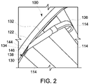
- FIG. 2 is a schematic view of a system 132 including an insertion apparatus 134 and a guide tube 136 positioned in the primary cavity of turbine assembly 100.
- FIG. 3 is a schematic view of insertion apparatus 134 traveling along an annular cavity 138 of turbine assembly 100. Annular cavity 138 extends along a circumference of a respective shroud 122 of turbine assembly 100.
- shrouds 122 are at least partially supported by a hanger and extend circumferentially around blades 114, 116 and alongside a turbine central frame 140.
- Clips 142 couple shrouds 122 to hangers and secure shrouds 122 in position during operation of turbine assembly 100.
- clips 142 are C-shaped and extend at least partially into annular cavity 138. Clips 142 are spaced apart along the circumference of each shroud 122. Accordingly, clips 142 are difficult to access from the exterior of turbine assembly 100 or from the primary cavity of turbine assembly 100.
- Insertion apparatus 134 is sized and shaped to fit within annular cavity 138 and facilitates inspection and/or repair at locations within annular cavity 138 that are difficult to access from an exterior of turbine assembly 100 by conventional means, such as using a borescope tool. Specifically, in contrast to at least some known insertion apparatus, insertion apparatus 134 is configured to extend into annular cavity 138 to facilitate inspection of clips 142.
- insertion apparatus 134 enters turbine assembly 100 through any suitable access port or opening of turbine assembly 100.
- insertion apparatus 134 enters and/or exits turbine assembly 100 through any of inlet 102 (shown in FIG. 1 ), exhaust 112 (shown in FIG. 1 ), and/or an access port, such as an igniter, borescope, or fuel nozzle port.
- insertion apparatus 134 is sized and shaped to fit within turbine assembly 100 and to travel along annular cavity 138.
- insertion apparatus 134 has a height, length, and width that are less than a clearance required to fit within annular cavity 138.
- insertion apparatus 134 is any size and shape that enables insertion apparatus 134 to operate as described herein.
- guide tube 136 extends through a port of turbine assembly 100 and defines a path for insertion apparatus 134.
- guide tube 136 defines an interior space sized to receive insertion apparatus 134 and allow insertion apparatus 134 to travel through guide tube 136.
- Guide tube 136 may be fixed to turbine assembly 100 by a flange (not shown) coupled to a port of turbine assembly 100.
- a flange extends around guide tube 136 and is sized to fit onto a port of turbine assembly 100.
- guide tube 136 is coupled to turbine assembly 100 in any manner that enables guide tube 136 to operate as described herein.
- guide tube 136 is configured to direct insertion apparatus 134 into annular cavity 138 of turbine assembly 100.
- guide tube 136 is curved and defines a curved path for insertion apparatus 134.
- guide tube 136 is curved in three-dimensions and has a helical shape. Accordingly, guide tube 136 is able to guide insertion apparatus 134 around obstacles in the primary cavity of turbine assembly 100.
- guide tube 136 is sized such that a tip 144 of guide tube 136 is positioned proximate a target area within turbine assembly 100, e.g., an opening into annular cavity 138.
- guide tube 136 is any size and shape that enables guide tube 136 to operate as described herein.
- insertion apparatus 134 is used to inspect and/or repair any interior components of turbine assembly 100.
- insertion apparatus 134 is positioned adjacent a portion of interior surface 130 of turbine assembly 100 within annular cavity 138. Interior surface 130 may include a surface of clips 142.
- insertion apparatus 134 detects a characteristic of interior surface 130.
- insertion apparatus 134 is used to generate an image of interior surface 130 and the image is examined to determine the condition of turbine assembly 100 and assess whether repairs are necessary.
- insertion apparatus 134 includes a sensor that detects characteristics of interior surface 130. If repairs are necessary, in some embodiments, insertion apparatus 134 is used to repair interior surface 130. After inspection and/or repair of interior surface 130, insertion apparatus 134 exits turbine assembly 100 through any suitable access port or opening of turbine assembly 100, such as via the route of entry.
- FIG. 4 is a side view of a portion of insertion apparatus 134.
- Insertion apparatus 134 includes an insertion end 146 and a steering end 148 opposite insertion end 146.
- Insertion end 146 is positionable within annular cavity 138 (shown in FIG. 3 ) of turbine assembly 100 (shown in FIG. 1 ) at target locations, such as adjacent clips 142 (shown in FIG. 3 ).
- insertion end 146 is shaped to facilitate movement of insertion apparatus 134 through annular cavity 138 (shown in FIG. 3 ) without insertion apparatus 134 being caught on objects.
- insertion end 146 is curved.
- insertion end 146 is angled, e.g., insertion end 146 has a V-shape.
- insertion apparatus 134 includes at least one maintenance device 150 coupled to insertion end 146 of insertion apparatus 134 to allow insertion apparatus 134 to perform an inspection and/or repair operation within annular cavity 138 (shown in FIG. 3 ) of turbine assembly 100 (shown in FIG. 1 ).
- maintenance device 150 includes at least one sensor 152 that is configured to contact surfaces.
- sensor 152 is an eddy current sensor.
- insertion apparatus 134 includes any maintenance device 150 that enables insertion apparatus 134 to operate as described herein.
- maintenance device 150 of insertion apparatus 134 includes, without limitation, any of the following: an applicator, a drill, a grinder, a heater, a welding electrode, a sprayer, an optical sensor (e.g., visible, infrared, and/or multi-spectral sensor), a mechanical sensor (e.g., stylus profilometer, coordinate measurement probe, load transducer, linear variable differential transformer), a thermal sensor (e.g., pyrometer, thermocouple, resistance temperature detector), a magnetic sensor, an acoustic sensor (e.g., piezoelectric, microphone, ultrasound), and an electromagnetic sensor (e.g., eddy current, potential drop, x-ray).
- an applicator e.g., visible, infrared, and/or multi-spectral sensor
- a mechanical sensor e.g., stylus profilometer, coordinate measurement probe, load transducer, linear variable differential transformer
- a thermal sensor e.g., pyrometer, thermocouple, resistance temperature detector
- maintenance device 150 is positionable in a plurality of orientations using a displacement mechanism 154.
- maintenance device 150 is pivotably coupled to insertion end 146 of insertion apparatus 134.
- Displacement mechanism 154 includes a cable 156 extending from maintenance device 150 to steering end 148.
- Maintenance device 150 is selectively pivoted by manipulating cable 156.
- maintenance device 150 is positionable between a first orientation in which maintenance device 150 is aligned with a translation direction 158 of insertion apparatus 134 and a second orientation in which insertion apparatus 134 extends at an angle relative to translation direction 158.
- the ability to position maintenance device 150 in a plurality of orientations facilitates precise positioning of maintenance device 150 relative to a target location.
- maintenance device 150 is positionable in any manner that enables insertion apparatus 134 to operate as described herein.
- insertion apparatus 134 includes a body 160 extending from insertion end 146 to steering end 148.
- Body 160 is sized and shaped to fit within annular cavity 138 (shown in FIG. 3 ).
- body 160 includes a first surface 162, a second surface 164 opposite first surface 162, and edges 166 extending along first surface 162 and second surface 164.
- First surface 162 and second surface 164 extend from steering end 148 to insertion end 146 and define a thickness 168 of body 160 therebetween. Thickness 168 is less than a width of each of first surface 162 and second surface 164.
- thickness 168 of body 160 is less than about 0.02 inches.
- first surface 162 and second surface 164 are substantially smooth, e.g., free of bumps, perforations, folds, or other surface features. Accordingly, body 160 is ribbon-shaped. In alternative embodiments, body 160 has any shape that enables insertion apparatus 134 to function as described herein.
- body 160 is flexible and conforms to a curve of annular cavity 138.
- body 160 has a first stiffness and is configured to curve in a direction perpendicular to first surface 162 and second surface 164 along the curve of annular cavity 138. Accordingly, insertion apparatus 134 is able to travel within annular cavity 138 circumferentially along shroud 122 (shown in FIG. 2 ).
- body 160 has a length that is greater than a circumference of shroud 122 such that insertion apparatus 134 is configured to extend from the exterior of turbine assembly 100 (shown in FIG. 2 ), into annular cavity 138 (shown in FIG. 2 ) and through the entirety of annular cavity 138.
- body 160 includes at least one conductor 170, e.g., a flexible metal wire, encased within insulation 172.
- insertion apparatus 134 includes any body 160 that enables insertion apparatus 134 to operate as described herein.
- insertion apparatus 134 includes a stiffener 174 coupled to and extending along body 160 from steering end 148 to insertion end 146.
- stiffener 174 is coupled to body 160 or formed integrally with body 160.
- Stiffener 174 is configured to resist bending of body 160 and facilitate translation and steering of insertion apparatus 134 within annular cavity 138 (shown in FIG. 3 ).
- stiffener 174 prevents body 160 from folding as insertion apparatus 134 is moved.
- Stiffener 174 has a second stiffness greater than the first stiffness of body 160.
- stiffener 174 includes a material that has a greater stiffness per unit volume than the material of body 160.
- stiffener 174 has a thickness greater than thickness 168 of body 160.
- stiffener 174 includes at least one cable and/or at least one hollow tube extending from steering end 148 to insertion end 146.
- Stiffener 174 has a width that is less than a width of body 160 and allows some flexing of body 160.
- insertion apparatus 134 includes any stiffener 174 that enables insertion apparatus 134 to operate as described herein. In further embodiments, stiffener 174 is omitted.
- body 160 and/or stiffener 174 is configured to convey power and communication signals for maintenance device 150.
- maintenance device 150 transmits and receives signals and/or power using any wired and/or wireless connections.
- a component such as a harness or tether, extends from maintenance device 150 to the exterior of turbine assembly 100 and provides power to maintenance device 150, allows maintenance device 150 to send and/or receive signals, and/or transmits mechanical force, fluids, or thermal energy to maintenance device 150.
- FIG. 5 is a perspective view of guide tube 136.
- Guide tube 136 includes a body 176 and tip 144. Together body 176 and tip 144 define an interior cavity 178 sized to receive insertion apparatus 134 (shown in FIG. 4 ).
- Guide tube 136 is configured to guide insertion apparatus 134 (shown in FIG. 2 ) toward annular cavity 138 (shown in FIG. 2 ).
- Body 176 is substantially rigid relative to insertion apparatus 134 (shown in FIG. 2 ) such that body 176 does not deform when insertion apparatus 134 travels through guide tube 136.
- body 176 is curved in 3-dimensions and forms a helical shape. When positioned in a port of turbine assembly 100 (shown in FIG.
- guide tube 136 defines a path for insertion apparatus 134 around components of turbine assembly 100, such as blades 114 (shown in FIG. 2 ), and into annular cavity 138 (shown in FIG. 2 ).
- guide tube 136 includes any body 176 that enables guide tube 136 to function as described herein.
- body 176 is segmented and the segments of body 176 are positionable relative to each other.
- tip 144 is pliable and has a stiffness less than the stiffness of body 176.
- tip (144) is relatively flexible compared to the rest of guide tube 136. Accordingly, tip 144 may deform when contacted by insertion apparatus 134. Tip 144 facilitates guiding insertion apparatus 134 into the opening of annular cavity 138 when guide tube 136 is positioned proximate annular cavity 138.
- guide tube 136 includes any tip that enables guide tube 136 to function as described herein.
- FIG. 6 is a perspective view of an alternative embodiment of a displacement mechanism 200 for use with the insertion apparatus 134 (shown in FIGS. 2-4 ).
- Displacement mechanism 200 is configured to adjust the orientation of maintenance device 150 (shown in FIG. 4 ) relative to insertion end 146 (shown in FIG. 4 ) of insertion apparatus 134.
- displacement mechanism 200 includes an inflatable bladder 202 and a flexible tube 204 configured to deliver a fluid to inflatable bladder 202.
- Inflatable bladder 202 is configured to couple to maintenance device 150 (shown in FIG. 4 ).
- inflatable bladder 202 is configured to switch between a deflated position and an at least partially inflated position to adjust the position of maintenance device 150 relative to body 160 (shown in FIG. 4 ) of insertion apparatus 134 (shown in FIG. 4 ).
- flexible tube 204 extends from insertion end 146 (shown in FIG. 4 ) to steering end 148 (shown in FIG. 4 ) and is configured to carry fluid such as air, water, and/or any other suitable fluid to inflatable bladder 202.
- displacement mechanism 200 includes a valve or other regulatory mechanism to allow control of the fluid flow through flexible tube 204.
- flexible tube 204 provides stiffness to body 160 (shown in FIG. 4 ) and acts as stiffener 174 (shown in FIG. 4 ) of insertion apparatus 134 (shown in FIG. 4 ).
- FIG. 7 is a flow chart of an exemplary method 300 of inspecting turbine assembly 100 (shown in FIG. 1 ).
- method 300 includes positioning 302 guide tube 136 in a port of the rotary machine to define a path for insertion apparatus 134 into annular cavity 138 defined by shroud 122.
- a flange fits onto a port of turbine assembly 100 and couples guide tube 136 to turbine assembly 100.
- Guide tube 136 defines a path from an exterior of turbine assembly 100, through the port, and into annular cavity 138.
- Guide tube 136 is shaped to curve around obstacles within turbine assembly 100 and is sized such that tip 144 of guide tube 136 is positioned adjacent an opening into annular cavity 138.
- guide tube 136 defines any path that enables system 132 to operate as described herein.
- method 300 includes positioning 304 insertion apparatus 134 along the path and into annular cavity 138.
- insertion apparatus 134 is inserted into the interior cavity 178 of guide tube 136 and moved through guide tube 136.
- Guide tube 136 guides insertion apparatus 134 around obstacles within turbine assembly 100 and into annular cavity 138 as insertion apparatus 134 is moved along the path defined by guide tube 136.
- method 300 includes deforming tip 144 to guide insertion apparatus 134 into annular cavity 138.
- tip 144 has a stiffness less than the stiffness of body 176 and allows insertion apparatus 134 to transition smoothly from guide tube 136 and into annular cavity 138.
- method 300 includes directing 306 insertion end 146 of insertion apparatus 134 through annular cavity 138.
- insertion end 146 of insertion apparatus 134 is directed through annular cavity 138 using a steering interface located at steering end 148.
- insertion end 146 is directed by moving body 160 along translation direction 158. Insertion end 146 moves along the circumference of shroud 122 within annular cavity 138 as body 160 is moved in translation direction 158. After insertion end 146 has traveled around substantially the entire circumference of shroud 122 or has passed a desired target location, insertion apparatus 134 may be moved backwards along translation direction 158 within annular cavity 138. In alternative embodiments, insertion apparatus 134 is moved in any manner that enables insertion apparatus 134 to operate as described herein.
- method 300 includes positioning 308 maintenance device 150 coupled to insertion end 146 of insertion apparatus 134 adjacent a portion of the rotary machine using displacement mechanism 154.
- cable 156 of displacement mechanism 154 is used to pivot maintenance device 150 about insertion end 146 of insertion apparatus 134 such that maintenance device 150 contacts interior surface 130 of clips 142.
- inflatable bladder 202 (shown in FIG. 6 ) is inflated/deflated to adjust the position of maintenance device 150.
- method 300 includes detecting 310 a characteristic of an interior portion of the rotary machine using maintenance device 150.
- maintenance device 150 includes sensor 152 with electrodes that contact clips 142 within annular cavity 138 to determine a characteristic of clips 142.
- Displacement mechanism 154 facilitates maintenance device 150 properly contacting clips 142 or other components of turbine assembly 100. Accordingly, insertion apparatus 134 is able to provide accurate and reliable information for components along annular cavity 138.
- the above described embodiments provide a system for use with a rotary machine having an annular cavity.
- the system includes an insertion apparatus configured to position a maintenance device along the annular cavity of the rotary machine.
- the system includes a guide tube positionable in a port of the rotary machine and configured to guide the insertion apparatus into the annular cavity.
- the guide tube is curved and has a helical shape.
- the insertion apparatus is inserted along a path defined by the guide tube into the annular cavity and directed along the annular cavity.
- the insertion apparatus is sized and shaped to fit within and move along the annular cavity.
- the maintenance device is coupled to an insertion end of the insertion apparatus and is positionable relative to the rotary machine using a displacement mechanism. As a result, the system allows inspection and/or repair of components at locations within the annular cavity of the rotary machine.
- An exemplary technical effect of the methods, systems, and apparatus described herein includes at least one of: (a) reducing the time to inspect and/or repair a rotary device or other applicable circular mechanism; (b) increasing the accessibility of difficult-to-reach locations within a turbine assembly for inspection and/or in situ repair; (c) reducing the time that circular mechanisms are out of service for maintenance; (d) increasing the precision and/or reliability of inspection and repair of circular mechanisms; (e) reducing unplanned service outages for a circular mechanisms; (f) enhancing data capture for use in quantifying and/or modeling the service condition of at least some components of the circular mechanism; and (g) providing a system and method for inspecting shroud hanger clips within an annular cavity.
- Exemplary embodiments of methods and systems for use with rotary machines are not limited to the specific embodiments described herein, but rather, components of systems and/or steps of the methods may be utilized independently and separately from other components and/or steps described herein.
- the methods and systems may also be used in combination with other systems requiring inspection and/or repair of components, and are not limited to practice with only the systems and methods as described herein.
- the exemplary embodiment can be implemented and utilized in connection with many other applications, equipment, and systems that may benefit from using a service apparatus for inspection and/or repair.
Landscapes
- Engineering & Computer Science (AREA)
- Mechanical Engineering (AREA)
- General Engineering & Computer Science (AREA)
- Physics & Mathematics (AREA)
- General Physics & Mathematics (AREA)
- Structures Of Non-Positive Displacement Pumps (AREA)
- Instruments For Viewing The Inside Of Hollow Bodies (AREA)
- Steering Controls (AREA)
Applications Claiming Priority (2)
| Application Number | Priority Date | Filing Date | Title |
|---|---|---|---|
| IN201941040204 | 2019-10-04 | ||
| US16/696,025 US12405187B2 (en) | 2019-10-04 | 2019-11-26 | Insertion apparatus for use with rotary machines |
Publications (2)
| Publication Number | Publication Date |
|---|---|
| EP3816396A2 true EP3816396A2 (de) | 2021-05-05 |
| EP3816396A3 EP3816396A3 (de) | 2021-08-11 |
Family
ID=72709060
Family Applications (1)
| Application Number | Title | Priority Date | Filing Date |
|---|---|---|---|
| EP20199193.2A Pending EP3816396A3 (de) | 2019-10-04 | 2020-09-30 | Einführungsvorrichtung zur verwendung mit drehmaschinen |
Country Status (2)
| Country | Link |
|---|---|
| EP (1) | EP3816396A3 (de) |
| CN (1) | CN112610291A (de) |
Family Cites Families (9)
| Publication number | Priority date | Publication date | Assignee | Title |
|---|---|---|---|---|
| GB0020461D0 (en) * | 2000-08-18 | 2000-10-11 | Oliver Crispin Consulting Ltd | Improvements in and relating to the robotic positioning of a work tool to a sensor |
| US7097539B2 (en) * | 2003-11-18 | 2006-08-29 | Dieter Moeller | Rotary grinding apparatus for blending defects on turbine blades and associated method of use |
| US7146674B2 (en) * | 2004-03-16 | 2006-12-12 | United Technologies Corporation | Rotary probe for cleaning an internal cavity |
| EP2194834A2 (de) * | 2007-09-24 | 2010-06-16 | Jetprep Ltd. | Virtuelle kanal-aktivierungsvorrichtung zur verwendung bei der einführung eines endoskopischen instruments und zur renigung von körperhöhlen |
| EP2499531A1 (de) * | 2009-11-10 | 2012-09-19 | Siemens Aktiengesellschaft | Inspektionsvorrichtung und verfahren zum positionieren einer inspektionsvorrichtung |
| JP6153410B2 (ja) * | 2013-07-30 | 2017-06-28 | オリンパス株式会社 | ブレード検査装置及びブレード検査方法 |
| EP3023600B1 (de) * | 2014-11-24 | 2018-01-03 | Ansaldo Energia IP UK Limited | Motorgehäuseelement |
| US10144096B2 (en) * | 2016-03-22 | 2018-12-04 | General Electric Company | Gas turbine in situ inflatable bladders for on-wing repair |
| GB2553144B (en) * | 2016-08-26 | 2019-10-30 | Rolls Royce Plc | Apparatus for insertion into a cavity of an object |
-
2020
- 2020-09-29 CN CN202011053563.9A patent/CN112610291A/zh active Pending
- 2020-09-30 EP EP20199193.2A patent/EP3816396A3/de active Pending
Also Published As
| Publication number | Publication date |
|---|---|
| EP3816396A3 (de) | 2021-08-11 |
| CN112610291A (zh) | 2021-04-06 |
Similar Documents
| Publication | Publication Date | Title |
|---|---|---|
| US12405187B2 (en) | Insertion apparatus for use with rotary machines | |
| US11103964B2 (en) | Service apparatus for use with rotary machines | |
| CN110073079B (zh) | 用于维护涡轮组件的维护设备和方法 | |
| US12091981B2 (en) | Insertion tool and method | |
| EP3926149A1 (de) | Inspektions- und reparaturwerkzeug | |
| US10976220B2 (en) | Wireless antenna system for sensors on circumferential interior surface of turbomachine casing | |
| CN110691890B (zh) | 与旋转机器一起使用的维修装置 | |
| US11248465B2 (en) | Reconfigurable maintenance apparatus | |
| US10774680B1 (en) | Optical sensor for circumferential interior surface of turbomachine casing, and related method | |
| EP2698502A1 (de) | Verfahren zum Messen des Kalt-Spaltmaßes der Laufschaufelspitze einer Turbomaschine und Spitzenabstandsmessanordnung zur Durchführung des Verfahrens | |
| EP3159661A1 (de) | Flüssiges sensorsystem mit selbstjustierend drehbare ummantelung | |
| CN112664278A (zh) | 维修涡轮机的系统及方法 | |
| EP3816396A2 (de) | Einführungsvorrichtung zur verwendung mit drehmaschinen | |
| US11179820B2 (en) | Mounting system for tool for machining circumferential interior surface of turbomachine casing | |
| US20200392867A1 (en) | Sensor mounting for circumferential interior surface of turbomachine casing | |
| US11248495B2 (en) | Systems and methods for sensors on circumferential interior surface of turbomachine casing | |
| EP3658880B1 (de) | Systeme und verfahren zur inspektion von schaufeln oder flügeln bei turbomaschinen | |
| US11608756B2 (en) | Service apparatus for use with rotary machines |
Legal Events
| Date | Code | Title | Description |
|---|---|---|---|
| PUAI | Public reference made under article 153(3) epc to a published international application that has entered the european phase |
Free format text: ORIGINAL CODE: 0009012 |
|
| STAA | Information on the status of an ep patent application or granted ep patent |
Free format text: STATUS: THE APPLICATION HAS BEEN PUBLISHED |
|
| AK | Designated contracting states |
Kind code of ref document: A2 Designated state(s): AL AT BE BG CH CY CZ DE DK EE ES FI FR GB GR HR HU IE IS IT LI LT LU LV MC MK MT NL NO PL PT RO RS SE SI SK SM TR |
|
| PUAL | Search report despatched |
Free format text: ORIGINAL CODE: 0009013 |
|
| AK | Designated contracting states |
Kind code of ref document: A3 Designated state(s): AL AT BE BG CH CY CZ DE DK EE ES FI FR GB GR HR HU IE IS IT LI LT LU LV MC MK MT NL NO PL PT RO RS SE SI SK SM TR |
|
| RIC1 | Information provided on ipc code assigned before grant |
Ipc: F01D 5/00 20060101AFI20210708BHEP Ipc: F01D 21/00 20060101ALI20210708BHEP |
|
| STAA | Information on the status of an ep patent application or granted ep patent |
Free format text: STATUS: REQUEST FOR EXAMINATION WAS MADE |
|
| 17P | Request for examination filed |
Effective date: 20220207 |
|
| RBV | Designated contracting states (corrected) |
Designated state(s): AL AT BE BG CH CY CZ DE DK EE ES FI FR GB GR HR HU IE IS IT LI LT LU LV MC MK MT NL NO PL PT RO RS SE SI SK SM TR |
|
| STAA | Information on the status of an ep patent application or granted ep patent |
Free format text: STATUS: EXAMINATION IS IN PROGRESS |
|
| 17Q | First examination report despatched |
Effective date: 20231121 |