EP3816407B1 - Prallkühlung mit prallzellen auf der prallfläche - Google Patents
Prallkühlung mit prallzellen auf der prallfläche Download PDFInfo
- Publication number
- EP3816407B1 EP3816407B1 EP20205461.5A EP20205461A EP3816407B1 EP 3816407 B1 EP3816407 B1 EP 3816407B1 EP 20205461 A EP20205461 A EP 20205461A EP 3816407 B1 EP3816407 B1 EP 3816407B1
- Authority
- EP
- European Patent Office
- Prior art keywords
- impingement
- cells
- component
- group
- plate
- Prior art date
- Legal status (The legal status is an assumption and is not a legal conclusion. Google has not performed a legal analysis and makes no representation as to the accuracy of the status listed.)
- Active
Links
Images


Classifications
-
- F—MECHANICAL ENGINEERING; LIGHTING; HEATING; WEAPONS; BLASTING
- F01—MACHINES OR ENGINES IN GENERAL; ENGINE PLANTS IN GENERAL; STEAM ENGINES
- F01D—NON-POSITIVE DISPLACEMENT MACHINES OR ENGINES, e.g. STEAM TURBINES
- F01D5/00—Blades; Blade-carrying members; Heating, heat-insulating, cooling or antivibration means on the blades or the members
- F01D5/12—Blades
- F01D5/14—Form or construction
- F01D5/18—Hollow blades, i.e. blades with cooling or heating channels or cavities; Heating, heat-insulating or cooling means on blades
- F01D5/187—Convection cooling
-
- F—MECHANICAL ENGINEERING; LIGHTING; HEATING; WEAPONS; BLASTING
- F01—MACHINES OR ENGINES IN GENERAL; ENGINE PLANTS IN GENERAL; STEAM ENGINES
- F01D—NON-POSITIVE DISPLACEMENT MACHINES OR ENGINES, e.g. STEAM TURBINES
- F01D25/00—Component parts, details, or accessories, not provided for in, or of interest apart from, other groups
- F01D25/24—Casings; Casing parts, e.g. diaphragms, casing fastenings
- F01D25/246—Fastening of diaphragms or stator-rings
-
- F—MECHANICAL ENGINEERING; LIGHTING; HEATING; WEAPONS; BLASTING
- F01—MACHINES OR ENGINES IN GENERAL; ENGINE PLANTS IN GENERAL; STEAM ENGINES
- F01D—NON-POSITIVE DISPLACEMENT MACHINES OR ENGINES, e.g. STEAM TURBINES
- F01D11/00—Preventing or minimising internal leakage of working-fluid, e.g. between stages
- F01D11/08—Preventing or minimising internal leakage of working-fluid, e.g. between stages for sealing space between rotor blade tips and stator
-
- F—MECHANICAL ENGINEERING; LIGHTING; HEATING; WEAPONS; BLASTING
- F01—MACHINES OR ENGINES IN GENERAL; ENGINE PLANTS IN GENERAL; STEAM ENGINES
- F01D—NON-POSITIVE DISPLACEMENT MACHINES OR ENGINES, e.g. STEAM TURBINES
- F01D5/00—Blades; Blade-carrying members; Heating, heat-insulating, cooling or antivibration means on the blades or the members
- F01D5/12—Blades
- F01D5/14—Form or construction
- F01D5/18—Hollow blades, i.e. blades with cooling or heating channels or cavities; Heating, heat-insulating or cooling means on blades
- F01D5/186—Film cooling
-
- F—MECHANICAL ENGINEERING; LIGHTING; HEATING; WEAPONS; BLASTING
- F01—MACHINES OR ENGINES IN GENERAL; ENGINE PLANTS IN GENERAL; STEAM ENGINES
- F01D—NON-POSITIVE DISPLACEMENT MACHINES OR ENGINES, e.g. STEAM TURBINES
- F01D5/00—Blades; Blade-carrying members; Heating, heat-insulating, cooling or antivibration means on the blades or the members
- F01D5/12—Blades
- F01D5/14—Form or construction
- F01D5/18—Hollow blades, i.e. blades with cooling or heating channels or cavities; Heating, heat-insulating or cooling means on blades
- F01D5/187—Convection cooling
- F01D5/188—Convection cooling with an insert in the blade cavity to guide the cooling fluid, e.g. forming a separation wall
-
- F—MECHANICAL ENGINEERING; LIGHTING; HEATING; WEAPONS; BLASTING
- F23—COMBUSTION APPARATUS; COMBUSTION PROCESSES
- F23R—GENERATING COMBUSTION PRODUCTS OF HIGH PRESSURE OR HIGH VELOCITY, e.g. GAS-TURBINE COMBUSTION CHAMBERS
- F23R3/00—Continuous combustion chambers using liquid or gaseous fuel
- F23R3/002—Wall structures
-
- F—MECHANICAL ENGINEERING; LIGHTING; HEATING; WEAPONS; BLASTING
- F23—COMBUSTION APPARATUS; COMBUSTION PROCESSES
- F23R—GENERATING COMBUSTION PRODUCTS OF HIGH PRESSURE OR HIGH VELOCITY, e.g. GAS-TURBINE COMBUSTION CHAMBERS
- F23R3/00—Continuous combustion chambers using liquid or gaseous fuel
- F23R3/005—Combined with pressure or heat exchangers
-
- F—MECHANICAL ENGINEERING; LIGHTING; HEATING; WEAPONS; BLASTING
- F01—MACHINES OR ENGINES IN GENERAL; ENGINE PLANTS IN GENERAL; STEAM ENGINES
- F01D—NON-POSITIVE DISPLACEMENT MACHINES OR ENGINES, e.g. STEAM TURBINES
- F01D25/00—Component parts, details, or accessories, not provided for in, or of interest apart from, other groups
- F01D25/08—Cooling; Heating; Heat-insulation
- F01D25/12—Cooling
-
- F—MECHANICAL ENGINEERING; LIGHTING; HEATING; WEAPONS; BLASTING
- F01—MACHINES OR ENGINES IN GENERAL; ENGINE PLANTS IN GENERAL; STEAM ENGINES
- F01D—NON-POSITIVE DISPLACEMENT MACHINES OR ENGINES, e.g. STEAM TURBINES
- F01D9/00—Stators
- F01D9/02—Nozzles; Nozzle boxes; Stator blades; Guide conduits, e.g. individual nozzles
- F01D9/04—Nozzles; Nozzle boxes; Stator blades; Guide conduits, e.g. individual nozzles forming ring or sector
- F01D9/041—Nozzles; Nozzle boxes; Stator blades; Guide conduits, e.g. individual nozzles forming ring or sector using blades
-
- F—MECHANICAL ENGINEERING; LIGHTING; HEATING; WEAPONS; BLASTING
- F05—INDEXING SCHEMES RELATING TO ENGINES OR PUMPS IN VARIOUS SUBCLASSES OF CLASSES F01-F04
- F05D—INDEXING SCHEME FOR ASPECTS RELATING TO NON-POSITIVE-DISPLACEMENT MACHINES OR ENGINES, GAS-TURBINES OR JET-PROPULSION PLANTS
- F05D2220/00—Application
- F05D2220/30—Application in turbines
- F05D2220/32—Application in turbines in gas turbines
- F05D2220/323—Application in turbines in gas turbines for aircraft propulsion, e.g. jet engines
-
- F—MECHANICAL ENGINEERING; LIGHTING; HEATING; WEAPONS; BLASTING
- F05—INDEXING SCHEMES RELATING TO ENGINES OR PUMPS IN VARIOUS SUBCLASSES OF CLASSES F01-F04
- F05D—INDEXING SCHEME FOR ASPECTS RELATING TO NON-POSITIVE-DISPLACEMENT MACHINES OR ENGINES, GAS-TURBINES OR JET-PROPULSION PLANTS
- F05D2240/00—Components
- F05D2240/10—Stators
- F05D2240/11—Shroud seal segments
-
- F—MECHANICAL ENGINEERING; LIGHTING; HEATING; WEAPONS; BLASTING
- F05—INDEXING SCHEMES RELATING TO ENGINES OR PUMPS IN VARIOUS SUBCLASSES OF CLASSES F01-F04
- F05D—INDEXING SCHEME FOR ASPECTS RELATING TO NON-POSITIVE-DISPLACEMENT MACHINES OR ENGINES, GAS-TURBINES OR JET-PROPULSION PLANTS
- F05D2240/00—Components
- F05D2240/80—Platforms for stationary or moving blades
- F05D2240/81—Cooled platforms
-
- F—MECHANICAL ENGINEERING; LIGHTING; HEATING; WEAPONS; BLASTING
- F05—INDEXING SCHEMES RELATING TO ENGINES OR PUMPS IN VARIOUS SUBCLASSES OF CLASSES F01-F04
- F05D—INDEXING SCHEME FOR ASPECTS RELATING TO NON-POSITIVE-DISPLACEMENT MACHINES OR ENGINES, GAS-TURBINES OR JET-PROPULSION PLANTS
- F05D2250/00—Geometry
- F05D2250/10—Two-dimensional
- F05D2250/18—Two-dimensional patterned
-
- F—MECHANICAL ENGINEERING; LIGHTING; HEATING; WEAPONS; BLASTING
- F05—INDEXING SCHEMES RELATING TO ENGINES OR PUMPS IN VARIOUS SUBCLASSES OF CLASSES F01-F04
- F05D—INDEXING SCHEME FOR ASPECTS RELATING TO NON-POSITIVE-DISPLACEMENT MACHINES OR ENGINES, GAS-TURBINES OR JET-PROPULSION PLANTS
- F05D2260/00—Function
- F05D2260/20—Heat transfer, e.g. cooling
- F05D2260/201—Heat transfer, e.g. cooling by impingement of a fluid
-
- F—MECHANICAL ENGINEERING; LIGHTING; HEATING; WEAPONS; BLASTING
- F05—INDEXING SCHEMES RELATING TO ENGINES OR PUMPS IN VARIOUS SUBCLASSES OF CLASSES F01-F04
- F05D—INDEXING SCHEME FOR ASPECTS RELATING TO NON-POSITIVE-DISPLACEMENT MACHINES OR ENGINES, GAS-TURBINES OR JET-PROPULSION PLANTS
- F05D2260/00—Function
- F05D2260/20—Heat transfer, e.g. cooling
- F05D2260/202—Heat transfer, e.g. cooling by film cooling
-
- F—MECHANICAL ENGINEERING; LIGHTING; HEATING; WEAPONS; BLASTING
- F05—INDEXING SCHEMES RELATING TO ENGINES OR PUMPS IN VARIOUS SUBCLASSES OF CLASSES F01-F04
- F05D—INDEXING SCHEME FOR ASPECTS RELATING TO NON-POSITIVE-DISPLACEMENT MACHINES OR ENGINES, GAS-TURBINES OR JET-PROPULSION PLANTS
- F05D2260/00—Function
- F05D2260/20—Heat transfer, e.g. cooling
- F05D2260/221—Improvement of heat transfer
- F05D2260/2214—Improvement of heat transfer by increasing the heat transfer surface
- F05D2260/22141—Improvement of heat transfer by increasing the heat transfer surface using fins or ribs
-
- F—MECHANICAL ENGINEERING; LIGHTING; HEATING; WEAPONS; BLASTING
- F23—COMBUSTION APPARATUS; COMBUSTION PROCESSES
- F23R—GENERATING COMBUSTION PRODUCTS OF HIGH PRESSURE OR HIGH VELOCITY, e.g. GAS-TURBINE COMBUSTION CHAMBERS
- F23R2900/00—Special features of, or arrangements for continuous combustion chambers; Combustion processes therefor
- F23R2900/03044—Impingement cooled combustion chamber walls or subassemblies
-
- F—MECHANICAL ENGINEERING; LIGHTING; HEATING; WEAPONS; BLASTING
- F23—COMBUSTION APPARATUS; COMBUSTION PROCESSES
- F23R—GENERATING COMBUSTION PRODUCTS OF HIGH PRESSURE OR HIGH VELOCITY, e.g. GAS-TURBINE COMBUSTION CHAMBERS
- F23R2900/00—Special features of, or arrangements for continuous combustion chambers; Combustion processes therefor
- F23R2900/03045—Convection cooled combustion chamber walls provided with turbolators or means for creating turbulences to increase cooling
-
- Y—GENERAL TAGGING OF NEW TECHNOLOGICAL DEVELOPMENTS; GENERAL TAGGING OF CROSS-SECTIONAL TECHNOLOGIES SPANNING OVER SEVERAL SECTIONS OF THE IPC; TECHNICAL SUBJECTS COVERED BY FORMER USPC CROSS-REFERENCE ART COLLECTIONS [XRACs] AND DIGESTS
- Y02—TECHNOLOGIES OR APPLICATIONS FOR MITIGATION OR ADAPTATION AGAINST CLIMATE CHANGE
- Y02T—CLIMATE CHANGE MITIGATION TECHNOLOGIES RELATED TO TRANSPORTATION
- Y02T50/00—Aeronautics or air transport
- Y02T50/60—Efficient propulsion technologies, e.g. for aircraft
Definitions
- the present invention relates to impingement cooling with increased cross-flow area, for example, for components of gas turbine engines.
- Impingement is an effective, widely used type of cooling system that is employed in jet propulsion type systems (e.g., gas turbine engines).
- Various components of gas turbine engines can benefit from impingement cooling in order to maintain, for example, appropriate operational conditions and/or to maximize component life.
- impingement cooling may be employed on vanes, blades, combustor panels, and blade outer air seals ("BOAS"). Accordingly, it may be advantageous to provide improved impingement cooling to improve part life or provide other features/benefits.
- EP0905353A1 , EP1043479A2 , JP2013019348A , EP3214270A1 , CN103075202A , EP3048262A1 , EP3379148A1 and US 2003/140632 disclose impingement assembly configurations.
- an impingement assembly as claimed in claim 1.
- the geometric shape of the impingement cells of the first group may be rounded rectangular.
- the geometric shape of the impingement cells of the first group may be one of a rectangle, a square, a triangle, a pentagon, a circle, an oval, and a hexagon.
- the raised walls may be one of curved, bumper-shaped, or rib-shaped in cross-section.
- a component of a gas turbine engine comprising the impingement assembly according to the first aspect.
- the impingement surface of the impingement assembly may be a hot portion of the component of the gas turbine engine.
- the component may be an airfoil and the impingement surface is a hot section surface of the airfoil.
- the component may be a blade outer air seal and the impingement surface is a hot section surface of the blade outer air seal.
- the component may be a combustor panel and the impingement surface is a hot section surface of the combustor panel.
- a gas turbine engine comprising: a hot section component having a hot wall; and the impingement assembly according to the first aspect; wherein the impingement surface is defined on a surface of the hot wall and the impingement plate is arranged relative to the hot wall.
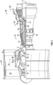
- FIG. 1 schematically illustrates a gas turbine engine 20.
- the exemplary gas turbine engine 20 is a two-spool turbofan engine that generally incorporates a fan section 22, a compressor section 24, a combustor section 26, and a turbine section 28.
- the fan section 22 drives air along a bypass flow path B, while the compressor section 24 drives air along a core flow path C for compression and communication into the combustor section 26.
- Hot combustion gases generated in the combustor section 26 are expanded through the turbine section 28.
- FIG. 1 schematically illustrates a gas turbine engine 20.
- the exemplary gas turbine engine 20 is a two-spool turbofan engine that generally incorporates a fan section 22, a compressor section 24, a combustor section 26, and a turbine section 28.
- the fan section 22 drives air along a bypass flow path B
- the compressor section 24 drives air along a core flow path C for compression and communication into the combustor section 26.
- Hot combustion gases generated in the combustor section 26 are expanded through the turbine section
- the gas turbine engine 20 generally includes a low speed spool 30 and a high speed spool 32 mounted for rotation about an engine centerline longitudinal axis A.
- the low speed spool 30 and the high speed spool 32 may be mounted relative to an engine static structure 33 via several bearing systems 31. It should be understood that other bearing systems 31 may alternatively or additionally be provided.
- the low speed spool 30 generally includes an inner shaft 34 that interconnects a fan 36, a low pressure compressor 38 and a low pressure turbine 39.
- the inner shaft 34 can be connected to the fan 36 through a geared architecture 45 to drive the fan 36 at a lower speed than the low speed spool 30.
- the high speed spool 32 includes an outer shaft 35 that interconnects a high pressure compressor 37 and a high pressure turbine 40.
- the inner shaft 34 and the outer shaft 35 are supported at various axial locations by bearing systems 31 positioned within the engine static structure 33.
- a combustor 42 is arranged between the high pressure compressor 37 and the high pressure turbine 40.
- a mid-turbine frame 44 may be arranged generally between the high pressure turbine 40 and the low pressure turbine 39.
- the mid-turbine frame 44 can support one or more bearing systems 31 of the turbine section 28.
- the mid-turbine frame 44 may include one or more airfoils 46 that extend within the core flow path C.
- the inner shaft 34 and the outer shaft 35 are concentric and rotate via the bearing systems 31 about the engine centerline longitudinal axis A, which is co-linear with their longitudinal axes.
- the core airflow is compressed by the low pressure compressor 38 and the high pressure compressor 37, is mixed with fuel and burned in the combustor 42, and is then expanded over the high pressure turbine 40 and the low pressure turbine 39.
- the high pressure turbine 40 and the low pressure turbine 39 rotationally drive the respective high speed spool 32 and the low speed spool 30 in response to the expansion.
- Each of the compressor section 24 and the turbine section 28 may include alternating rows of rotor assemblies and vane assemblies (shown schematically) that carry airfoils that extend into the core flow path C.
- the rotor assemblies can carry a plurality of rotating blades 25, while each vane assembly can carry a plurality of vanes 27 that extend into the core flow path C.
- the blades 25 of the rotor assemblies add or extract energy from the core airflow that is communicated through the gas turbine engine 20 along the core flow path C.
- the vanes 27 of the vane assemblies direct the core airflow to the blades 25 to either add or extract energy.
- Various components of a gas turbine engine 20 including but not limited to the airfoils of the blades 25 and the vanes 27 of the compressor section 24 and the turbine section 28, may be subjected to repetitive thermal cycling under widely ranging temperatures and pressures.
- the hardware of the turbine section 28 is particularly subjected to relatively extreme operating conditions. Therefore, some components may require internal cooling circuits for cooling the parts during engine operation.
- Example cooling circuits that include features such as airflow bleed ports are discussed below.
- an intermediate spool includes an intermediate pressure compressor ("IPC") between a low pressure compressor (“LPC”) and a high pressure compressor (“HPC”), and an intermediate pressure turbine (“IPT”) between the high pressure turbine (“HPT”) and the low pressure turbine (“LPT”)).
- IPC intermediate pressure compressor
- HPC low pressure compressor
- HPC high pressure compressor
- IPT intermediate pressure turbine
- FIG. 2 is a schematic view of a turbine section.
- Turbine 200 includes a plurality of airfoils, including, for example, one or more blades 201 and vanes 202.
- the airfoils 201, 202 may be hollow bodies with internal cavities defining a number of channels or cavities, hereinafter airfoil cavities, formed therein and extending from an inner diameter 206 to an outer diameter 208, or vice-versa.
- the airfoil cavities may be separated by partitions within the airfoils 201, 202 that may extend either from the inner diameter 206 or the outer diameter 208 of the airfoil 201, 202.
- the partitions may extend for a portion of the length of the airfoil 201, 202, but may stop or end prior to forming a complete wall within the airfoil 201, 202.
- each of the airfoil cavities may be fluidly connected and form a fluid path within the respective airfoil 201, 202.
- the blades 201 and the vanes 202 may include platforms 210 located proximal to the inner diameter thereof. Located below the platforms 210 may be airflow ports and/or bleed orifices that enable air to bleed from the internal cavities of the airfoils 201, 202. A root of the airfoil may connected to or be part of the platform 210.
- the turbine 200 is housed within a case 212, which may have multiple parts (e.g., turbine case, diffuser case, etc.). In various locations, components, such as seals, may be positioned between airfoils 201, 202 and the case 212.
- blade outer air seals 214 (hereafter "BOAS") are located radially outward from the blades 201.
- the BOAS 214 can include BOAS supports that are configured to fixedly connect or attach the BOAS 214 to the case 212 (e.g., the BOAS supports can be located between the BOAS and the case).
- the case 212 includes a plurality of hooks 218 that engage with the hooks 216 to secure the BOAS 214 between the case 212 and a tip of the blade 201.
- Impingement cooling can be used to provide cooling to various components of gas turbine engines, including, but not limited to, blades, vanes, blade outer air seals, combustor panels, other hot section components, etc.
- Impingement-type cooling can be adjusted or optimized by selecting or defining a specific or desired arrangement of the characteristics or parameters of the impingement holes. For example, impingement hole diameter, impingement hole spacing, and depth-to-diameter ratio of the impingement hole can all be adjusted, selected, or otherwise designed to achieve desired impingement cooling.
- the impingement hole depth is an important factor for effective cooling and optimal or preferred impingement hole depth may tend toward being small (e.g., a short or shallow impingement hole). However, having a small (e.g., short depth) impingement hole depth can increase cross-flow air velocity that "blows away" impingement jets and therefore reduces impingement effectiveness.
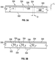
- FIGS. 3A-3B side view illustrations of an impingement plate 320 positioned proximate to an impingement surface 322 in accordance with the prior art is shown.
- the impingement surface 322 is a surface of a component that is to be cooled (e.g., a surface of an airfoil, a surface of a combustor, a surface of a BOAS, etc.).
- the impingement surface 322 may be a backside of a hot wall or portion of a hot section component of a gas turbine engine.
- the impingement plate 320 is positioned about and near the impingement surface 322 to provide cooling to the impingement surface 322. As shown, the impingement plate 320 includes a plurality of impingement holes 324. The impingement holes 324 can be arranged in a grid-like pattern on the impingement plate 320 or may be otherwise arranged or positioned to provide a desired cooling to the impingement surface 322. An impingement cavity is defined as the space between the impingement plate 320 and the impingement surface 322.
- the impingement plate 320 has a first surface 326 and a second surface 328, with the impingement holes 324 extending through the impingement plate 320 from the first surface 326 to the second surface 328.
- the impingement plate 320 has an impingement plate thickness (i.e., the distance from the first surface 326 to the second surface 328) that defines an impingement hole depth L. Further, each impingement hole 324 has an impingement hole diameter D.
- a cross-flow area 330 is defined between the impingement surface 322 and the first surface 326 of the impingement plate 320.
- the cross-flow area 330 has an impingement cavity height X that is defined as the distance between the first surface 326 and the impingement surface 322, as shown.
- the cross-flow area 330 defines at least a portion of the impingement cavity that is defined between the impingement plate 320 and the impingement surface 322.
- impingement cooling typically it is desirable to provide impingement cooling by optimizing the impingement hole diameter D and positioning the impingement plate 320 at a specific impingement hole height X from the impingement surface 322.
- having a small (e.g., short depth) impingement hole depth can increase cross-flow air velocity that "blows away" impingement jets and therefore can reduce impingement effectiveness. That is, air flowing within the cross-flow area 330 can reduce the effectiveness of impingement cooling by having too high of a velocity as the cross-flow air passes through the cross-flow area 330. As shown in FIG.
- the cross-flow air 332 flows in a cross-flow direction between the impingement plate 320 and the impingement surface 322 (e.g., left-to-right in FIG. 3 , and indicated by the arrows of cross-flow air 332).
- static zones 334 may be formed at areas of the impingement surface 322 that are between the location of the impingement holes 324.
- the static zones 334 are formed as a result of adjacent impinging air 336 that interacts and cancel each other out such that no cooling (or minimal cooling) may result. That is, as the impinging air 336 impinges upon the impingement surface 322, the cooling air may be reflected off the impingement surface 322 and cancel by interaction with adjacent flows of impinging air 336. Accordingly, the combination of cross-flow air 332 in the cross-flow direction and the static zones 334, cooling effectiveness provided by the impingement holes 324 may be reduced.
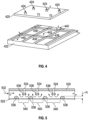
- FIG. 4 an isometric illustration of an impingement plate 420 positioned proximate to an impingement surface 422 is shown.
- the impingement surface 422 is a surface of a component that is to be cooled (e.g., a surface of an airfoil, a surface of a combustor, a surface of a BOAS, etc.).
- the impingement plate 420 is positioned relative and near the impingement surface 422 to provide cooling to the impingement surface 422.
- the impingement plate 420 includes a plurality of impingement holes 424.
- the impingement holes 424 can be arranged in a grid-like pattern on the impingement plate 420 or may be otherwise arranged or positioned to provide a desired cooling to the impingement surface 422.
- the impingement surface 422 includes a gridded pattern defined by a raised wall 438 that extends from the impingement surface 422 toward the impingement plate 420.
- the raised wall 438 defines a plurality of impingement cells 440.
- the impingement cells 440 are defined by a flat surface that is part of the impingement surface 422 and bounded by the raised wall 438.
- the gridded pattern of the raised wall 438 defines the geometric shape of each impingement cell 440.
- the gridded pattern of the raised wall 438 may be arranged relative to anticipated or modeled static zones (e.g., static zones 334 shown in FIG. 3B ), such that the raised walls 438 are arranged where a static zone would exist if no raised wall was present.
- the impingement cells 440 may be associated with an impingement hole 424 of the impingement plate 420.
- the impingement cells 440 defined by the raised walls 438 may be centered relative to a corresponding impingement hole 424 such that impinging air through a respective impingement hole 424 and toward the impingement surface 422 will be centered within a respective impingement cell 440 defined on the impingement surface 422.
- the raised walls 438 are arranged at the locations of anticipated static zones, as the impinging air reflects off the impingement surface 422 and back toward the impingement plate 420, the air will flow along surfaces of the raised walls 438 and provide cooling to the material thereof. As such, the static zones of reduced or no cooling may be eliminated. Furthermore, the raised walls may also address cross-flow concerns. For example, the raised walls 438 may protect the floor of each impingement cell 440 (i.e., part of the impingement surface 422) from a cross-flow. That is, the raised walls 438 may block a portion of the cross-flow, and particularly a portion of the cross-flow around the location at which an impinging air impinges upon the impingement surface 422. As such, the cross-flow will have reduced impact, such as a reduced ability to push or distort the impinging air, thereby increasing an efficiency or efficacy of the impinging air directed on the impingement surface 422 within each impingement cell 440.
- the raised walls 438 may be curved, bumper-shaped, or rib-shaped such that they may be conducive to cooling flow flowing along the surface of the raised walls 438 from a respective impingement cell 440. As such, in cross-section, the geometry of the raised wall 438 may be domed or protruding from the impingement surface 422.
- FIG. 5 a cross-sectional illustration of an impingement surface 522 arranged relative to an impingement plate 520 is shown.
- the impingement plate 520 includes a plurality of impingement holes 524 that are arranged to directed impinging air 536 toward the impingement surface 522.
- the impingement surface 522 includes a gridded pattern defined by a raised wall 538 that extends from the impingement surface 522 toward the impingement plate 520.
- the raised wall 538 may be a continuous wall structure or pattern that defines a plurality of impingement cells 540, with a floor of each impingement cell 540 being a portion of the impingement surface 522.
- a portion of the impinging air 536, after impinging upon the floor of the impingement cells 540, will flow along or over surfaces of the raised wall 538.
- This flow may enable heat flux conduction from the material of the impingement surface 522 (e.g., a hot section surface of a gas turbine engine) and thus maximum temperatures of the material may be reduced.
- typical static zones (described above) may be reduced or eliminated, and additional or improved cooling may be provided at locations of an impingement surface between impingement holes of an impingement plate.
- the raised wall 538 may also reduce the impacts of cross-flow 532. Specifically, because the raised wall 538 extends from the impingement surface 522 toward the impingement plate 520, the cross-flow 532 may be blocked and thus will not reduce the effectiveness of the impinging air 536 as it is impinged upon the impingement surface 522. As shown in FIG. 5 , the raised wall 538 has a wall height H that is a height of the raised wall 538 in a direction extending from the impingement surface 522 toward the impingement plate 520.
- the cross-flow 532 will have less volume to pass through, which will increase a velocity of the cross-flow 532, which can encourage improved heat removal at the location of the raised wall 538.
- improved convection cooling may be provided in locations of typical or conventional static zones (described above). That is, the raised wall 538 will modify the volume of the impingement cavity defined between the impingement plate 520 and the impingement surface 522.
- the impingement cells defined by a patterned raised wall, described above may be substantially uniform.
- the size, shape, and geometry of each impingement cell may be different, or sets of different size, shape, and geometry impingement cells may be employed and defined by a raised wall that is on an impingement surface.
- FIG. 6 at top down plan view illustration of an impingement surface 622 having a raised wall 638 extending therefrom is shown.
- the raised wall 638 defines a plurality of impingement cells 640, as described above.
- each impingement cell is aligned and centered on the location of a respective impingement hole 624 that is in an impingement plate that is arranged relative to the impingement surface 622.
- the impingement cells 640 have generally rectangular geometry (e.g., bath-tub shaped, rounded rectangle, etc.), with curved corners. Although shown with the impingement cells 640 having a substantially rectangular shape, with curved corners, such geometry is not so limiting. Furthermore, in FIG. 6 , each of the impingement cells 640 is shown being the same as all other impingement cells 640. However, in other examples, there may be variation in the shape, size, geometry, etc. of the impingement cells. Additionally, in this example, the impingement cells 640 are arranged such that the respective impingement holes 624 are center-aligned with the shape/geometry of the respective impingement cell 640. However, such alignment is not to be limiting.
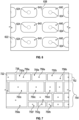
- FIG. 7 a top down plan view illustration of an impingement surface 722 having a raised wall 738 extending therefrom is shown.
- the raised wall 738 defines a plurality of impingement cells 750a-h, which will be described in two groups, a first group 752 and a second group 754.
- the first group 752 of impingement cells 750a-750b includes substantially similar and uniform impingement cell size and geometry. Some of the impingement cells 750a of the first group 752 are geometrically aligned with respective impingement holes 756a and other impingement cells 750b are arranged with a geometric center that is offset from a respective impingement hole 756b.
- the offset location of the impingement hole 756b relative to the geometry of the impingement cell 750b may be set based on cross-flow velocities, heating conditions on a hot side of the impingement surface 722, or based on other parameters.
- the second group 754 of impingement cells 750c-750h includes a variety of geometries and sizes of impingement cells. Each impingement cell 750c-750h is geometrically center-aligned with a respective impingement hole. As illustrated, some impingement cells 750c, 750e, 750f, 750g may be rectangular in shape, and other impingement cells 750d, 750h may be square in shape. Further, as shown, some impingement cells may be larger (or smaller) in one or more dimensions (e.g., length or width within the plane of the impingement surface 722) as compared to other impingement cells.
- impingement cells 9 pattern 970 with raised walls 972 and hexagon impingement cells 974), and other polygons (with or without curved corners), circular, oval, rounded, and/or combinations thereof.
- various different geometries of impingement cells may be arranged on a single impingement surface such that different geometric shapes are arranged adjacent to each other (e.g., triangle next to rectangular).
- a raised wall extends in a direction toward an impingement plate (when installed relative thereto) such that respective impingement cells are defined and arranged relative to respective impingement holes within the impingement plate (whether geometrically center-aligned or geometrically center-offset).
- FIG. 10 illustrates a geometric pattern 1080 of impingement cells 1084 defined by raised walls 1082, as described above, but with a set of triangular bath tub impingement cells, with sub-bath tub impingement cells 1086, and multiple impingement holes 1088 associated therewith.
- examples described herein provide improved impingement cooling by partially blocking a cross-flow (with a raised wall) and enabling cooling at typical static zones because the raised wall is arranged at the static zones.
- Such raised walls may partially block local cross-flow and provide conduction cooling into the otherwise dead zones (static zones).
- the term "about” is intended to include the degree of error associated with measurement of the particular quantity based upon the equipment available at the time of filing the application. For example, “about” may include a range of ⁇ 8%, or 5%, or 2% of a given value or other percentage change as will be appreciated by those of skill in the art for the particular measurement and/or dimensions referred to herein.
Landscapes
- Engineering & Computer Science (AREA)
- Mechanical Engineering (AREA)
- General Engineering & Computer Science (AREA)
- Chemical & Material Sciences (AREA)
- Combustion & Propulsion (AREA)
- Turbine Rotor Nozzle Sealing (AREA)
Claims (11)
- Prallbaugruppe, umfassend:eine Prallplatte (520), die eine Vielzahl von Pralllöchern (524; 756a, 756b) aufweist, die darin ausgebildet ist, um auftreffende Luft (536) in Richtung einer Prallfläche (522; 722) zu leiten;wobei die Prallfläche (522; 722) relativ zu der Prallplatte mit einem Prallhohlraum angeordnet ist, der zwischen der Prallplatte und der Prallfläche definiert ist, wobei die Prallfläche (522; 722) ein Gittermuster aus Prallzellen (540; 750a-h) beinhaltet, die durch erhöhte Wände (438; 538; 738) definiert sind;wobei sich die erhöhten Wände (438; 538; 738) in einer Richtung von der Prallfläche in Richtung der Prallplatte erstrecken, wobei sich eine Wandhöhe (H) der erhöhten Wände, die sich in der Richtung von der Prallfläche in Richtung der Prallplatte erstreckt, nicht bis zu der Prallplatte erstreckt, um das Volumen des Querstroms (532), der durch den Prallhohlraum strömt, zu verringern und die Wirksamkeit der auftreffenden Luft (536) beim Auftreffen auf die Prallfläche nicht zu verringern, und wobei die Vielzahl von Prallzellen jeweils eine geometrische Form auf der Prallfläche aufweist, wobei die Vielzahl von Prallzellen Folgendes umfasst:eine erste Gruppe (752) von Prallzellen (750a, 750b) und eine zweite Gruppe (754) von Prallzellen (750c-750h),wobei die erste Gruppe (752) eine im Wesentlichen ähnliche und einheitliche Prallzellengröße und -geometrie beinhaltet, undwobei die zweite Gruppe (754) eine Vielfalt von Geometrien von Prallzellen beinhaltet, wobei jede Prallzelle (750c-750h) einen geometrischen Mittelpunkt aufweist, der mit einem jeweiligen Prallloch ausgerichtet ist;gekennzeichnet durcheine Vielzahl von Prallzellen (750a) der ersten Gruppe (752), die jeweils geometrisch mit einem jeweiligen Prallloch (756a) ausgerichtet ist, und eine weitere Vielzahl von Prallzellen (750b) der ersten Gruppe, die jeweils einen geometrischen Mittelpunkt aufweist, der von einem jeweiligen Prallloch (756b) versetzt ist;wobei die zweite Gruppe (754) eine Vielfalt von Geometrien und Größen von Prallzellen (750c-750h) beinhaltet, wobei jede Prallzelle der zweiten Gruppe einen geometrischen Mittelpunkt aufweist, der mit einem jeweiligen Prallloch ausgerichtet ist; undwobei die erhöhten Wände (438; 538; 738) an Stellen statischer Zonen positioniert sind, die ohne das Vorhandensein der erhöhten Wände (438; 538; 738) zwischen den Pralllöchern existieren würden, wobei derartige statische Zonen Zonen verringerter Kühlung sind, die als ein Ergebnis der Wechselwirkung und Aufhebung benachbarter direkt auftreffender Luft (536) in der Abwesenheit der erhöhten Wände (438; 538; 738) ausgebildet würden.
- Prallbaugruppe nach Anspruch 1, wobei die geometrische Form der Prallzellen (750a-b) der ersten Gruppe (752) abgerundet rechteckig ist.
- Prallbaugruppe nach Anspruch 1, wobei die geometrische Form der Prallzellen (750a-b) der ersten Gruppe (752) eines von einem Rechteck, einem Quadrat, einem Dreieck, einem Fünfeck, einem Kreis, einem Oval oder einem Sechseck ist.
- Prallbaugruppe nach einem der vorhergehenden Ansprüche, wobei die erhöhten Wände (438; 538; 738) im Querschnitt stoßfängerförmig sind.
- Prallbaugruppe nach einem der Ansprüche 1 bis 3, wobei die erhöhten Wände (438; 538; 738) im Querschnitt gekrümmt oder rippenförmig sind.
- Komponente (201, 202, 214) eines Gasturbinentriebwerks (20), wobei die Komponente die Prallbaugruppe nach einem der vorhergehenden Ansprüche umfasst.
- Komponente nach Anspruch 6, wobei die Prallfläche (522; 722) der Prallbaugruppe ein heißer Teil der Komponente (201, 202, 214) des Gasturbinentriebwerks (20) ist.
- Komponente nach Anspruch 7, wobei die Komponente ein Schaufelblatt (201, 202) ist und die Prallfläche eine Heißabschnittsfläche des Schaufelblatts ist.
- Komponente nach Anspruch 7, wobei die Komponente eine äußere Laufschaufelluftdichtung (214) ist und die Prallfläche eine Heißabschnittsfläche der äußeren Laufschaufelluftdichtung ist.
- Komponente nach Anspruch 7, wobei die Komponente eine Brennkammerplatte ist und die Prallfläche eine Heißabschnittsfläche der Brennkammerplatte ist.
- Gasturbinentriebwerk (20), umfassend:eine Heißabschnittskomponente (201, 202, 214), die eine heiße Wand aufweist; unddie Prallbaugruppe nach einem der Ansprüche 1 bis 5;wobei die Prallfläche (522; 722) auf einer Fläche der heißen Wand definiert ist und die Prallplatte (520) relativ zu der heißen Wand angeordnet ist.
Applications Claiming Priority (1)
| Application Number | Priority Date | Filing Date | Title |
|---|---|---|---|
| US16/672,781 US11131199B2 (en) | 2019-11-04 | 2019-11-04 | Impingement cooling with impingement cells on impinged surface |
Publications (2)
| Publication Number | Publication Date |
|---|---|
| EP3816407A1 EP3816407A1 (de) | 2021-05-05 |
| EP3816407B1 true EP3816407B1 (de) | 2024-07-17 |
Family
ID=73059584
Family Applications (1)
| Application Number | Title | Priority Date | Filing Date |
|---|---|---|---|
| EP20205461.5A Active EP3816407B1 (de) | 2019-11-04 | 2020-11-03 | Prallkühlung mit prallzellen auf der prallfläche |
Country Status (2)
| Country | Link |
|---|---|
| US (1) | US11131199B2 (de) |
| EP (1) | EP3816407B1 (de) |
Families Citing this family (5)
| Publication number | Priority date | Publication date | Assignee | Title |
|---|---|---|---|---|
| US10651112B2 (en) * | 2016-11-01 | 2020-05-12 | Massachusetts Institute Of Technology | Thermal management of RF devices using embedded microjet arrays |
| US10665529B2 (en) | 2017-07-21 | 2020-05-26 | Massachusetts Institute Of Technology | Modular microjet cooling of packaged electronic components |
| KR102502652B1 (ko) * | 2020-10-23 | 2023-02-21 | 두산에너빌리티 주식회사 | 물결 형태 유로를 구비한 배열 충돌제트 냉각구조 |
| CN113225997A (zh) * | 2021-05-13 | 2021-08-06 | 西北工业大学 | 一种带多级圆柱形凸台的强化冲击换热结构 |
| EP4276283B1 (de) * | 2022-05-13 | 2026-01-28 | Siemens Energy Global GmbH & Co. KG | Ringsegmentanordnung in einem gasturbinenmotor |
Citations (3)
| Publication number | Priority date | Publication date | Assignee | Title |
|---|---|---|---|---|
| EP0905353B1 (de) * | 1997-09-30 | 2003-01-15 | ALSTOM (Switzerland) Ltd | Prallanordnung für ein konvektives Kühl- oder Heizverfahren |
| EP1043479B1 (de) * | 1999-04-06 | 2005-12-07 | General Electric Company | Turbinenwand mit Rillen an der Innenseite |
| EP3379148B1 (de) * | 2017-03-20 | 2019-11-20 | United Technologies Corporation | Brennkammerauskleidung mit dichtung für einen gasturbinenmotor |
Family Cites Families (17)
| Publication number | Priority date | Publication date | Assignee | Title |
|---|---|---|---|---|
| US5259730A (en) * | 1991-11-04 | 1993-11-09 | General Electric Company | Impingement cooled airfoil with bonding foil insert |
| JP3110227B2 (ja) | 1993-11-22 | 2000-11-20 | 株式会社東芝 | タービン冷却翼 |
| DE59709153D1 (de) * | 1997-07-03 | 2003-02-20 | Alstom Switzerland Ltd | Prallanordnung für ein konvektives Kühl-oder Heizverfahren |
| US6688110B2 (en) * | 2000-01-18 | 2004-02-10 | Rolls-Royce Plc | Air impingement cooling system |
| GB0405322D0 (en) | 2004-03-10 | 2004-04-21 | Rolls Royce Plc | Impingement cooling arrangement |
| US8667682B2 (en) * | 2011-04-27 | 2014-03-11 | Siemens Energy, Inc. | Method of fabricating a nearwall nozzle impingement cooled component for an internal combustion engine |
| JP5791405B2 (ja) | 2011-07-12 | 2015-10-07 | 三菱重工業株式会社 | 回転機械の翼体 |
| JP5927893B2 (ja) | 2011-12-15 | 2016-06-01 | 株式会社Ihi | インピンジ冷却機構、タービン翼及び燃焼器 |
| JP5834876B2 (ja) | 2011-12-15 | 2015-12-24 | 株式会社Ihi | インピンジ冷却機構、タービン翼及び燃焼器 |
| US9181813B2 (en) * | 2012-07-05 | 2015-11-10 | Siemens Aktiengesellschaft | Air regulation for film cooling and emission control of combustion gas structure |
| CN103075202A (zh) | 2013-01-15 | 2013-05-01 | 上海交通大学 | 涡轮叶片内部带有栅格扰流的冲击冷却结构 |
| DE102013003444A1 (de) * | 2013-02-26 | 2014-09-11 | Rolls-Royce Deutschland Ltd & Co Kg | Prall-effusionsgekühlte Schindel einer Gasturbinenbrennkammer mit verlängerten Effusionsbohrungen |
| WO2015130377A2 (en) * | 2013-12-12 | 2015-09-03 | United Technologies Corporation | Structural honeycomb panel |
| EP3048262A1 (de) | 2015-01-20 | 2016-07-27 | Alstom Technology Ltd | Wand für einen Heißgaskanal in einer Gasturbine |
| EP3332095A1 (de) * | 2015-08-06 | 2018-06-13 | Siemens Aktiengesellschaft | Komponente mit prallgekühlten taschen, die durch erhöhte rippen gebildet sind, und einer deckblechdiffusion, die mit den erhöhten rippen verbunden ist |
| US10352177B2 (en) | 2016-02-16 | 2019-07-16 | General Electric Company | Airfoil having impingement openings |
| EP3425174A1 (de) | 2017-07-03 | 2019-01-09 | Siemens Aktiengesellschaft | Anordnung mit geführtem kühlluftstrom zur querflussverringerung in einer gasturbine |
-
2019
- 2019-11-04 US US16/672,781 patent/US11131199B2/en active Active
-
2020
- 2020-11-03 EP EP20205461.5A patent/EP3816407B1/de active Active
Patent Citations (3)
| Publication number | Priority date | Publication date | Assignee | Title |
|---|---|---|---|---|
| EP0905353B1 (de) * | 1997-09-30 | 2003-01-15 | ALSTOM (Switzerland) Ltd | Prallanordnung für ein konvektives Kühl- oder Heizverfahren |
| EP1043479B1 (de) * | 1999-04-06 | 2005-12-07 | General Electric Company | Turbinenwand mit Rillen an der Innenseite |
| EP3379148B1 (de) * | 2017-03-20 | 2019-11-20 | United Technologies Corporation | Brennkammerauskleidung mit dichtung für einen gasturbinenmotor |
Also Published As
| Publication number | Publication date |
|---|---|
| EP3816407A1 (de) | 2021-05-05 |
| US20210131290A1 (en) | 2021-05-06 |
| US11131199B2 (en) | 2021-09-28 |
Similar Documents
| Publication | Publication Date | Title |
|---|---|---|
| EP3816407B1 (de) | Prallkühlung mit prallzellen auf der prallfläche | |
| JP5072277B2 (ja) | 逆向きの流れ膜冷却壁 | |
| US7186084B2 (en) | Hot gas path component with mesh and dimpled cooling | |
| US11448076B2 (en) | Engine component with cooling hole | |
| EP1445424B1 (de) | Hohlschaufel mit eingebautem Kreislauf zur Schaufelspitzenkühlung | |
| US9470096B2 (en) | Turbine bucket with notched squealer tip | |
| EP3290639B1 (de) | Prallkühlung mit erhöhtem querströmungsbereich | |
| EP3734015B1 (de) | Schaufelblatt und zugehöriges gasturbinentriebwerk | |
| US11773729B2 (en) | Component for a gas turbine engine with a film hole | |
| EP3088675A1 (de) | Laufschaufel mit aufgeweiteter spitze und zugehörige gasturbine | |
| EP2878767A1 (de) | Turbine mit Endwandmikroschaltungskühlung | |
| US7967568B2 (en) | Gas turbine component with reduced cooling air requirement | |
| US9045988B2 (en) | Turbine bucket with squealer tip | |
| US11927110B2 (en) | Component for a turbine engine with a cooling hole | |
| JP4433139B2 (ja) | タービンブレード壁の冷却装置及び製造方法 | |
| CA1190480A (en) | Vane structure having improved cooled operation in stationary combustion turbines | |
| EP2912276B1 (de) | Filmkühlkanalanordnung | |
| EP3246519B1 (de) | Aktiv gekühltes bauteil | |
| EP3567218B1 (de) | Schaufelblatt mit verbessertem vorderkantenkühlschema und beschädigungswiderstand | |
| EP3564486B1 (de) | Schaufel mit verbessertem kühlschema | |
| EP1533481A2 (de) | Heissgaskomponente mit einer netzartigen Vertiefungen aufweisenden Kühlstruktur | |
| CA2967099C (en) | Actively cooled component |
Legal Events
| Date | Code | Title | Description |
|---|---|---|---|
| PUAI | Public reference made under article 153(3) epc to a published international application that has entered the european phase |
Free format text: ORIGINAL CODE: 0009012 |
|
| STAA | Information on the status of an ep patent application or granted ep patent |
Free format text: STATUS: THE APPLICATION HAS BEEN PUBLISHED |
|
| AK | Designated contracting states |
Kind code of ref document: A1 Designated state(s): AL AT BE BG CH CY CZ DE DK EE ES FI FR GB GR HR HU IE IS IT LI LT LU LV MC MK MT NL NO PL PT RO RS SE SI SK SM TR |
|
| STAA | Information on the status of an ep patent application or granted ep patent |
Free format text: STATUS: REQUEST FOR EXAMINATION WAS MADE |
|
| 17P | Request for examination filed |
Effective date: 20211103 |
|
| RBV | Designated contracting states (corrected) |
Designated state(s): AL AT BE BG CH CY CZ DE DK EE ES FI FR GB GR HR HU IE IS IT LI LT LU LV MC MK MT NL NO PL PT RO RS SE SI SK SM TR |
|
| STAA | Information on the status of an ep patent application or granted ep patent |
Free format text: STATUS: EXAMINATION IS IN PROGRESS |
|
| 17Q | First examination report despatched |
Effective date: 20230424 |
|
| RAP3 | Party data changed (applicant data changed or rights of an application transferred) |
Owner name: RTX CORPORATION |
|
| GRAP | Despatch of communication of intention to grant a patent |
Free format text: ORIGINAL CODE: EPIDOSNIGR1 |
|
| STAA | Information on the status of an ep patent application or granted ep patent |
Free format text: STATUS: GRANT OF PATENT IS INTENDED |
|
| INTG | Intention to grant announced |
Effective date: 20240207 |
|
| GRAS | Grant fee paid |
Free format text: ORIGINAL CODE: EPIDOSNIGR3 |
|
| GRAA | (expected) grant |
Free format text: ORIGINAL CODE: 0009210 |
|
| STAA | Information on the status of an ep patent application or granted ep patent |
Free format text: STATUS: THE PATENT HAS BEEN GRANTED |
|
| AK | Designated contracting states |
Kind code of ref document: B1 Designated state(s): AL AT BE BG CH CY CZ DE DK EE ES FI FR GB GR HR HU IE IS IT LI LT LU LV MC MK MT NL NO PL PT RO RS SE SI SK SM TR |
|
| REG | Reference to a national code |
Ref country code: CH Ref legal event code: EP |
|
| REG | Reference to a national code |
Ref country code: DE Ref legal event code: R096 Ref document number: 602020034027 Country of ref document: DE |
|
| REG | Reference to a national code |
Ref country code: IE Ref legal event code: FG4D |
|
| REG | Reference to a national code |
Ref country code: LT Ref legal event code: MG9D |
|
| REG | Reference to a national code |
Ref country code: NL Ref legal event code: MP Effective date: 20240717 |
|
| PG25 | Lapsed in a contracting state [announced via postgrant information from national office to epo] |
Ref country code: PT Free format text: LAPSE BECAUSE OF FAILURE TO SUBMIT A TRANSLATION OF THE DESCRIPTION OR TO PAY THE FEE WITHIN THE PRESCRIBED TIME-LIMIT Effective date: 20241118 |
|
| REG | Reference to a national code |
Ref country code: AT Ref legal event code: MK05 Ref document number: 1704330 Country of ref document: AT Kind code of ref document: T Effective date: 20240717 |
|
| PG25 | Lapsed in a contracting state [announced via postgrant information from national office to epo] |
Ref country code: NL Free format text: LAPSE BECAUSE OF FAILURE TO SUBMIT A TRANSLATION OF THE DESCRIPTION OR TO PAY THE FEE WITHIN THE PRESCRIBED TIME-LIMIT Effective date: 20240717 |
|
| PG25 | Lapsed in a contracting state [announced via postgrant information from national office to epo] |
Ref country code: PT Free format text: LAPSE BECAUSE OF FAILURE TO SUBMIT A TRANSLATION OF THE DESCRIPTION OR TO PAY THE FEE WITHIN THE PRESCRIBED TIME-LIMIT Effective date: 20241118 Ref country code: NL Free format text: LAPSE BECAUSE OF FAILURE TO SUBMIT A TRANSLATION OF THE DESCRIPTION OR TO PAY THE FEE WITHIN THE PRESCRIBED TIME-LIMIT Effective date: 20240717 |
|
| PG25 | Lapsed in a contracting state [announced via postgrant information from national office to epo] |
Ref country code: NO Free format text: LAPSE BECAUSE OF FAILURE TO SUBMIT A TRANSLATION OF THE DESCRIPTION OR TO PAY THE FEE WITHIN THE PRESCRIBED TIME-LIMIT Effective date: 20241017 |
|
| PG25 | Lapsed in a contracting state [announced via postgrant information from national office to epo] |
Ref country code: GR Free format text: LAPSE BECAUSE OF FAILURE TO SUBMIT A TRANSLATION OF THE DESCRIPTION OR TO PAY THE FEE WITHIN THE PRESCRIBED TIME-LIMIT Effective date: 20241018 Ref country code: FI Free format text: LAPSE BECAUSE OF FAILURE TO SUBMIT A TRANSLATION OF THE DESCRIPTION OR TO PAY THE FEE WITHIN THE PRESCRIBED TIME-LIMIT Effective date: 20240717 Ref country code: PL Free format text: LAPSE BECAUSE OF FAILURE TO SUBMIT A TRANSLATION OF THE DESCRIPTION OR TO PAY THE FEE WITHIN THE PRESCRIBED TIME-LIMIT Effective date: 20240717 |
|
| PG25 | Lapsed in a contracting state [announced via postgrant information from national office to epo] |
Ref country code: BG Free format text: LAPSE BECAUSE OF FAILURE TO SUBMIT A TRANSLATION OF THE DESCRIPTION OR TO PAY THE FEE WITHIN THE PRESCRIBED TIME-LIMIT Effective date: 20240717 |
|
| PG25 | Lapsed in a contracting state [announced via postgrant information from national office to epo] |
Ref country code: LV Free format text: LAPSE BECAUSE OF FAILURE TO SUBMIT A TRANSLATION OF THE DESCRIPTION OR TO PAY THE FEE WITHIN THE PRESCRIBED TIME-LIMIT Effective date: 20240717 |
|
| PG25 | Lapsed in a contracting state [announced via postgrant information from national office to epo] |
Ref country code: IS Free format text: LAPSE BECAUSE OF FAILURE TO SUBMIT A TRANSLATION OF THE DESCRIPTION OR TO PAY THE FEE WITHIN THE PRESCRIBED TIME-LIMIT Effective date: 20241117 Ref country code: AT Free format text: LAPSE BECAUSE OF FAILURE TO SUBMIT A TRANSLATION OF THE DESCRIPTION OR TO PAY THE FEE WITHIN THE PRESCRIBED TIME-LIMIT Effective date: 20240717 |
|
| PG25 | Lapsed in a contracting state [announced via postgrant information from national office to epo] |
Ref country code: HR Free format text: LAPSE BECAUSE OF FAILURE TO SUBMIT A TRANSLATION OF THE DESCRIPTION OR TO PAY THE FEE WITHIN THE PRESCRIBED TIME-LIMIT Effective date: 20240717 |
|
| PG25 | Lapsed in a contracting state [announced via postgrant information from national office to epo] |
Ref country code: ES Free format text: LAPSE BECAUSE OF FAILURE TO SUBMIT A TRANSLATION OF THE DESCRIPTION OR TO PAY THE FEE WITHIN THE PRESCRIBED TIME-LIMIT Effective date: 20240717 Ref country code: RS Free format text: LAPSE BECAUSE OF FAILURE TO SUBMIT A TRANSLATION OF THE DESCRIPTION OR TO PAY THE FEE WITHIN THE PRESCRIBED TIME-LIMIT Effective date: 20241017 |
|
| PG25 | Lapsed in a contracting state [announced via postgrant information from national office to epo] |
Ref country code: RS Free format text: LAPSE BECAUSE OF FAILURE TO SUBMIT A TRANSLATION OF THE DESCRIPTION OR TO PAY THE FEE WITHIN THE PRESCRIBED TIME-LIMIT Effective date: 20241017 Ref country code: PL Free format text: LAPSE BECAUSE OF FAILURE TO SUBMIT A TRANSLATION OF THE DESCRIPTION OR TO PAY THE FEE WITHIN THE PRESCRIBED TIME-LIMIT Effective date: 20240717 Ref country code: NO Free format text: LAPSE BECAUSE OF FAILURE TO SUBMIT A TRANSLATION OF THE DESCRIPTION OR TO PAY THE FEE WITHIN THE PRESCRIBED TIME-LIMIT Effective date: 20241017 Ref country code: LV Free format text: LAPSE BECAUSE OF FAILURE TO SUBMIT A TRANSLATION OF THE DESCRIPTION OR TO PAY THE FEE WITHIN THE PRESCRIBED TIME-LIMIT Effective date: 20240717 Ref country code: IS Free format text: LAPSE BECAUSE OF FAILURE TO SUBMIT A TRANSLATION OF THE DESCRIPTION OR TO PAY THE FEE WITHIN THE PRESCRIBED TIME-LIMIT Effective date: 20241117 Ref country code: HR Free format text: LAPSE BECAUSE OF FAILURE TO SUBMIT A TRANSLATION OF THE DESCRIPTION OR TO PAY THE FEE WITHIN THE PRESCRIBED TIME-LIMIT Effective date: 20240717 Ref country code: GR Free format text: LAPSE BECAUSE OF FAILURE TO SUBMIT A TRANSLATION OF THE DESCRIPTION OR TO PAY THE FEE WITHIN THE PRESCRIBED TIME-LIMIT Effective date: 20241018 Ref country code: FI Free format text: LAPSE BECAUSE OF FAILURE TO SUBMIT A TRANSLATION OF THE DESCRIPTION OR TO PAY THE FEE WITHIN THE PRESCRIBED TIME-LIMIT Effective date: 20240717 Ref country code: ES Free format text: LAPSE BECAUSE OF FAILURE TO SUBMIT A TRANSLATION OF THE DESCRIPTION OR TO PAY THE FEE WITHIN THE PRESCRIBED TIME-LIMIT Effective date: 20240717 Ref country code: BG Free format text: LAPSE BECAUSE OF FAILURE TO SUBMIT A TRANSLATION OF THE DESCRIPTION OR TO PAY THE FEE WITHIN THE PRESCRIBED TIME-LIMIT Effective date: 20240717 Ref country code: AT Free format text: LAPSE BECAUSE OF FAILURE TO SUBMIT A TRANSLATION OF THE DESCRIPTION OR TO PAY THE FEE WITHIN THE PRESCRIBED TIME-LIMIT Effective date: 20240717 |
|
| PG25 | Lapsed in a contracting state [announced via postgrant information from national office to epo] |
Ref country code: RO Free format text: LAPSE BECAUSE OF FAILURE TO SUBMIT A TRANSLATION OF THE DESCRIPTION OR TO PAY THE FEE WITHIN THE PRESCRIBED TIME-LIMIT Effective date: 20240717 Ref country code: DK Free format text: LAPSE BECAUSE OF FAILURE TO SUBMIT A TRANSLATION OF THE DESCRIPTION OR TO PAY THE FEE WITHIN THE PRESCRIBED TIME-LIMIT Effective date: 20240717 Ref country code: SM Free format text: LAPSE BECAUSE OF FAILURE TO SUBMIT A TRANSLATION OF THE DESCRIPTION OR TO PAY THE FEE WITHIN THE PRESCRIBED TIME-LIMIT Effective date: 20240717 |
|
| REG | Reference to a national code |
Ref country code: DE Ref legal event code: R097 Ref document number: 602020034027 Country of ref document: DE |
|
| PG25 | Lapsed in a contracting state [announced via postgrant information from national office to epo] |
Ref country code: EE Free format text: LAPSE BECAUSE OF FAILURE TO SUBMIT A TRANSLATION OF THE DESCRIPTION OR TO PAY THE FEE WITHIN THE PRESCRIBED TIME-LIMIT Effective date: 20240717 |
|
| PG25 | Lapsed in a contracting state [announced via postgrant information from national office to epo] |
Ref country code: CZ Free format text: LAPSE BECAUSE OF FAILURE TO SUBMIT A TRANSLATION OF THE DESCRIPTION OR TO PAY THE FEE WITHIN THE PRESCRIBED TIME-LIMIT Effective date: 20240717 |
|
| PG25 | Lapsed in a contracting state [announced via postgrant information from national office to epo] |
Ref country code: SK Free format text: LAPSE BECAUSE OF FAILURE TO SUBMIT A TRANSLATION OF THE DESCRIPTION OR TO PAY THE FEE WITHIN THE PRESCRIBED TIME-LIMIT Effective date: 20240717 |
|
| PLBE | No opposition filed within time limit |
Free format text: ORIGINAL CODE: 0009261 |
|
| STAA | Information on the status of an ep patent application or granted ep patent |
Free format text: STATUS: NO OPPOSITION FILED WITHIN TIME LIMIT |
|
| 26N | No opposition filed |
Effective date: 20250422 |
|
| REG | Reference to a national code |
Ref country code: CH Ref legal event code: PL |
|
| PG25 | Lapsed in a contracting state [announced via postgrant information from national office to epo] |
Ref country code: MC Free format text: LAPSE BECAUSE OF FAILURE TO SUBMIT A TRANSLATION OF THE DESCRIPTION OR TO PAY THE FEE WITHIN THE PRESCRIBED TIME-LIMIT Effective date: 20240717 |
|
| PG25 | Lapsed in a contracting state [announced via postgrant information from national office to epo] |
Ref country code: LU Free format text: LAPSE BECAUSE OF NON-PAYMENT OF DUE FEES Effective date: 20241103 |
|
| REG | Reference to a national code |
Ref country code: CH Ref legal event code: PL |
|
| PG25 | Lapsed in a contracting state [announced via postgrant information from national office to epo] |
Ref country code: CH Free format text: LAPSE BECAUSE OF NON-PAYMENT OF DUE FEES Effective date: 20241130 |
|
| REG | Reference to a national code |
Ref country code: BE Ref legal event code: MM Effective date: 20241130 |
|
| PG25 | Lapsed in a contracting state [announced via postgrant information from national office to epo] |
Ref country code: SE Free format text: LAPSE BECAUSE OF FAILURE TO SUBMIT A TRANSLATION OF THE DESCRIPTION OR TO PAY THE FEE WITHIN THE PRESCRIBED TIME-LIMIT Effective date: 20240717 |
|
| PG25 | Lapsed in a contracting state [announced via postgrant information from national office to epo] |
Ref country code: BE Free format text: LAPSE BECAUSE OF NON-PAYMENT OF DUE FEES Effective date: 20241130 |
|
| PG25 | Lapsed in a contracting state [announced via postgrant information from national office to epo] |
Ref country code: IE Free format text: LAPSE BECAUSE OF NON-PAYMENT OF DUE FEES Effective date: 20241103 |
|
| PGFP | Annual fee paid to national office [announced via postgrant information from national office to epo] |
Ref country code: DE Payment date: 20251022 Year of fee payment: 6 |
|
| PGFP | Annual fee paid to national office [announced via postgrant information from national office to epo] |
Ref country code: GB Payment date: 20251023 Year of fee payment: 6 |
|
| PGFP | Annual fee paid to national office [announced via postgrant information from national office to epo] |
Ref country code: FR Payment date: 20251022 Year of fee payment: 6 |
|
| PG25 | Lapsed in a contracting state [announced via postgrant information from national office to epo] |
Ref country code: IT Free format text: LAPSE BECAUSE OF FAILURE TO SUBMIT A TRANSLATION OF THE DESCRIPTION OR TO PAY THE FEE WITHIN THE PRESCRIBED TIME-LIMIT Effective date: 20240717 |
|
| PG25 | Lapsed in a contracting state [announced via postgrant information from national office to epo] |
Ref country code: HU Free format text: LAPSE BECAUSE OF FAILURE TO SUBMIT A TRANSLATION OF THE DESCRIPTION OR TO PAY THE FEE WITHIN THE PRESCRIBED TIME-LIMIT; INVALID AB INITIO Effective date: 20201103 |
|
| PG25 | Lapsed in a contracting state [announced via postgrant information from national office to epo] |
Ref country code: CY Free format text: LAPSE BECAUSE OF FAILURE TO SUBMIT A TRANSLATION OF THE DESCRIPTION OR TO PAY THE FEE WITHIN THE PRESCRIBED TIME-LIMIT; INVALID AB INITIO Effective date: 20201103 |