EP3816464B1 - Bouchon à vis - Google Patents
Bouchon à vis Download PDFInfo
- Publication number
- EP3816464B1 EP3816464B1 EP20190974.4A EP20190974A EP3816464B1 EP 3816464 B1 EP3816464 B1 EP 3816464B1 EP 20190974 A EP20190974 A EP 20190974A EP 3816464 B1 EP3816464 B1 EP 3816464B1
- Authority
- EP
- European Patent Office
- Prior art keywords
- screw cap
- screw
- head
- screw head
- wheel
- Prior art date
- Legal status (The legal status is an assumption and is not a legal conclusion. Google has not performed a legal analysis and makes no representation as to the accuracy of the status listed.)
- Active
Links
Images


Classifications
-
- F—MECHANICAL ENGINEERING; LIGHTING; HEATING; WEAPONS; BLASTING
- F16—ENGINEERING ELEMENTS AND UNITS; GENERAL MEASURES FOR PRODUCING AND MAINTAINING EFFECTIVE FUNCTIONING OF MACHINES OR INSTALLATIONS; THERMAL INSULATION IN GENERAL
- F16B—DEVICES FOR FASTENING OR SECURING CONSTRUCTIONAL ELEMENTS OR MACHINE PARTS TOGETHER, e.g. NAILS, BOLTS, CIRCLIPS, CLAMPS, CLIPS OR WEDGES; JOINTS OR JOINTING
- F16B37/00—Nuts or like thread-engaging members
- F16B37/14—Cap nuts; Nut caps or bolt caps
-
- B—PERFORMING OPERATIONS; TRANSPORTING
- B60—VEHICLES IN GENERAL
- B60B—VEHICLE WHEELS; CASTORS; AXLES FOR WHEELS OR CASTORS; INCREASING WHEEL ADHESION
- B60B3/00—Disc wheels, i.e. wheels with load-supporting disc body
- B60B3/14—Attaching disc body to hub ; Wheel adapters
- B60B3/16—Attaching disc body to hub ; Wheel adapters by bolts or the like
- B60B3/165—Attaching disc body to hub ; Wheel adapters by bolts or the like with locking devices for the fixing means, e.g. screw or nut covers
-
- F—MECHANICAL ENGINEERING; LIGHTING; HEATING; WEAPONS; BLASTING
- F16—ENGINEERING ELEMENTS AND UNITS; GENERAL MEASURES FOR PRODUCING AND MAINTAINING EFFECTIVE FUNCTIONING OF MACHINES OR INSTALLATIONS; THERMAL INSULATION IN GENERAL
- F16B—DEVICES FOR FASTENING OR SECURING CONSTRUCTIONAL ELEMENTS OR MACHINE PARTS TOGETHER, e.g. NAILS, BOLTS, CIRCLIPS, CLAMPS, CLIPS OR WEDGES; JOINTS OR JOINTING
- F16B41/00—Measures against loss of bolts, nuts, or pins; Measures against unauthorised operation of bolts, nuts or pins
- F16B41/005—Measures against unauthorised operation of bolts, nuts or pins
Definitions
- the invention concerns a screw cap for covering wheel screws including wheel fasteners, such as wheel bolts, and anti-theft wheel fasteners.
- present invention relates to a screw cap suitable for installation with two different screw head types.
- the screw cap of the present invention is generally used in the automotive industry, for example, the screw cap may be installed onto wheel fasteners and anti-theft wheel fasteners of cars, vans, heavy goods vehicles, buses and the like.
- Wheel screws generally include wheel fasteners, including bolts, screws, nuts and the like, and serve to affix a wheel of a vehicle to a wheel hub of a vehicle.
- Some screw sets for wheels may include at least one anti-theft wheel fasteners, which are substantially similar to wheel fasteners, except that they include a specifically designed head that can only be used with a corresponding key for installation or removal of the anti-theft wheel fasteners.
- the key and the head of an anti-theft wheel fastener are generally unique.
- each wheel may include a single anti-theft wheel fastener, and a plurality of normal wheel fasteners (i.e. normal screw heads). In this way, the anti-theft wheel fastener prevents theft of the wheel from the vehicle.
- a screw cap 10 having a generally hexagonal engaging portion may be used to affix the screw cap to a hexagonal head of a wheel fastener.
- a screw cap 10 having a generally cylindrical engaging portion may be used to affix the screw cap to a circular head of an anti-theft wheel fasteners. In this way, two different screw caps are required to protect wheel fasteners and anti-theft wheel fasteners.
- the present invention proposes a single screw cap that can be used with two types of screw head. More particularly, the screw cap can be used with both wheel fastener screw heads and anti-theft wheel fastener screw heads. More particularly, the present invention proposes a screw cap that reduces manufacturing time, costs and is more aesthetically suitable for the end user.
- a screw cap for a screw head comprising a tubular body, having an end wall at a distal end portion and an opening at a proximal end portion along a centre axis; at least one first coupling member arranged coaxially to said centre axis at said distal end portion, adapted to retainingly receive at least a portion of a first-type screw head; and at least one second coupling member arranged coaxially with, and axially proximal to, said at least one first coupling member, adapted to retainingly receive at least a portion of a second-type screw head.
- This provides the advantage that a single screw cap can be manufactured and installed to accommodate two types of wheel screw head.
- this provides the advantage that a single screw cap may be manufactured and installed to accommodate both a head of a wheel fastener and a head of an anti-theft wheel fasteners.
- said second coupling member comprises at least two circumferentially spaced apart rib members, each rib member extending radially inwardly from an inner surface of said tubular body so as to couplingly engage with at least a portion of the second-type screw head, during use.
- said at least two rib members are adapted to provide a friction fit with at least a portion of the second-type screw head, during use.
- the screw cap comprises at least six circumferentially equidistantly spaced apart rib members.
- the diameter defined by the circumferentially spaced apart rib members is greater than the diameter defined by the annularly shaped recess.
- each screw cap installed to a wheel screw on a wheel of a vehicle appears substantially identical in height and form once installed, irrespective of the wheel screw to which the screw cap is affixed.
- the first-type screw head is a hexagonal screw head.
- the second-type screw head is a circular screw head.
- the screw cap comprises a resilient material.
- the screw cap comprises a polymer material.
- the end wall comprises a central bore adapted to receive a corresponding tool key.
- the described example embodiment relates to a screw cap, and in particular a screw cap which can be installed onto two different types of screw heads. More particularly, the screw cap can be installed onto both a head of a wheel fastener and a head of an-anti theft wheel fastener.
- the terms 'connected', ⁇ affixed' and the like are intended to include direct connections between two members without any other members interposed therebetween, as well as, indirect connections between members in which one or more other members are interposed therebetween.
- the terminology includes the words specifically mentioned above, derivatives thereof, and words of similar import.
- the terms 'wheel screw', 'wheel fastener', 'screw', 'fastener' and the like may be used interchangeably.
- the terms 'screw cap', 'wheel cap', 'wheel screw cap', 'wheel fastener cap' and the like may be used interchangeably.
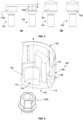
- a screw, or a wheel fastener 102 for example a bolt, includes a first-type screw head 102a, which is hexagonal in the depicted embodiment.
- the head 102a may have another shape in another embodiment.
- the wheel fastener 102 generally includes a threaded shank extending outwardly from the head 102a at a distal end thereof.
- Figure 2(b) shows another screw, or an anti-theft wheel fastener 104, for example a bolt, including a second-type screw head 104a, which is circular in the depicted embodiment.
- the anti-theft wheel fastener 104 generally includes a threaded shank extending outwardly from the head 104a at a distal end thereof.
- the first-type screw head 102a and the second-type screw head 104a are different.
- the head 104a includes a cut-out 104b for engaging with a corresponding tool key (not shown) in use, thereby allowing the user to install or remove the anti-theft wheel fastener 104.
- the head 104a and the cut-out 104b may have another shape in another embodiment.
- the wheel fastener 102 and the anti-theft wheel fastener 104, or indeed other appropriate screw means having any other appropriate shape or size, may be used with the screw cap of the present invention.
- the head 102a of the wheel fastener 102 may have a greater height than that of the head 104a of the anti-theft wheel fastener 104 (i.e. anti-theft screw).
- the difference between the height of each fastener 102, 104 is indicated by the double-headed arrow in Figure 3(a) .
- a screw cap 100 is placed over the head 102a, 104a of each fastener 102, 104 and pushed towards a threaded end of the respective fastener 102, 104 to attach the screw cap 100 to the fasteners 102, 104 as shown in Figure 3(b) .
- the screw cap 100 may generally be a push-fit or a friction-fit with respect to the respective fastener 102, 104. Additionally, as discussed in more detail below, the screw cap 100 is configured to accommodate the difference in height, diameter or shape of the heads 102a, 104a of the fasteners 102, 104 such that, after installation, the screw cap 100 provides a standardized visual appearance, as shown in Figure 3(b) .
- the screw cap 100 includes a generally tubular body 106 having a side wall 108.
- the body 106 of the present example is shown as a generally round tubular shape, but other shapes are contemplated in other embodiments.
- the body 106 includes an end wall 110 at a first, distal, end portion 130 and an opening 112 at a second, proximal, end portion 132.
- the proximal end portion 132 is generally formed at one end of a centre axis A, and the distal end portion 130 is generally formed to the other end of the centre axis A.
- the end wall 110 is the outermost portion of the screw cap 100, i.e. furthest away from the screw head, after installation.
- the body 106 includes a first coupling member including a plurality of first surrounding wall members 114.
- the screw cap 100 includes a generally cylindrical upstanding wall 122 located proximal the centre axis A of the screw cap 100 and internally of the first surrounding wall members 114.
- the upstanding wall 122 may be any shape.
- the upstanding wall 122 extends towards the open end 112 of the body 106 from the end wall 110.
- the upstanding wall 122 and the first surrounding wall members 114 generally define a substantially annularly shaped recess that is coaxial with the centre axis A of the body 106.
- the upstanding wall 122 generally encloses, and defines, a central bore 124 within the end wall 110.
- the central bore 124 may be arranged to receive a corresponding tool key.
- the central bore 124 provided within the end wall 110 may be any appropriate shape. Indeed, the central bore 124 may not be provided in some embodiments, such that the end wall 110 forms a closed end of the screw cap 100.
- the plurality of first surrounding I wall members 114 are arranged generally concentrically and facing the upstanding wall 122 thereby forming the substantially annularly shaped recess.
- first surrounding wall members 114 provided in a hexagonal arrangement are contemplated, however any number or arrangement of surrounding wall members 114 may be used in another embodiment.
- each of the surrounding wall members 114 may be formed as a unitary, or integral, component, thus providing a single surrounding wall member 114.
- the side wall 108 of the body 106 also includes a second coupling member including a plurality of circumferentially spaced apart rib members 118.
- Each rib member 118 extends radially inwardly from an inner surface of the side wall 108 towards the centre axis A of the body 106.
- the second coupling member, formed by the rib members 118 is coaxial and/or concentric with respect to the first coupling member, formed by the surrounding wall members 114.
- six rib members 118 that are equidistantly spaced apart are contemplated, however any number or arrangement of rib members 118 may be used in another embodiment.
- first shoulder members 116 connect each of the surrounding wall members 114 to a respective rib member 118. Each first shoulder member 116 generally defines a stop for the second-type screw head, as discussed below.
- second shoulder members 120 connect each of the surrounding wall members 114 to the upstanding wall 122. Each second shoulder member 120 generally defines a stop, or provides a predetermined height, for the first-type screw head, as discussed below.
- the predetermined height may be measured from a respective shoulder to the opening 112 of the body 106. In this way, the screw cap 100 can accommodate differences in the height of wheel screw heads, as discussed below.
- a first-type wheel screw having a first-type screw head for example the wheel fastener 102 as described above.
- the wheel fastener head 102a is generally hexagonal in the depicted embodiment, but other shapes are contemplated in other embodiments.
- the screw cap 100 is installed over the head 102a by pushing the screw cap 100 onto the head 102a. In this way the head 102a is clamped between the upstanding wall 122 and the plurality of surrounding I wall members 114. That is, the head 102a is secured between the upstanding wall 122 and each of the surrounding wall members 114 by a friction-fit.
- a second-type wheel screw having a second-type screw head for example an anti-theft wheel fastener 104 as described above.
- the second-type wheel screw is different to the first-type wheel screw.
- the first-type screw head is different to the second-type screw head.
- the shape and height of the screw heads are different, as described in relation to Figure 3 .
- the screw cap 100 is installed over the head 104a by pushing the screw cap 100 onto the head 104a.
- the head 104a is clamped by the plurality of rib members 118. That is, the head 104a is secured by each of the rib members 118 by a friction-fit.
- the difference in the predetermined height of the shoulders 116, 120 accommodates a difference in height of the screw heads 102a, 104a.
- the visual appearance is identical after installation, such that a user does not perceive a difference between the wheel screws 102, 104.
- the screw cap 100 After installation, if it is desired to remove the screw cap 100, the screw cap 100 is simply pulled in a direction opposition to that of the installation. More particularly, the central bore 124 may receive a corresponding tool key to aid removal.
- the screw cap 100 may comprise any suitable material, for example, a resilient material or a polymer material.
- the screw cap 100 may assume any appropriate shape, size, arrangement or the like.
Landscapes
- Engineering & Computer Science (AREA)
- Mechanical Engineering (AREA)
- General Engineering & Computer Science (AREA)
- Connection Of Plates (AREA)
- Dowels (AREA)
- Bolts, Nuts, And Washers (AREA)
Claims (9)
- Bouchon à vis (100) pour une tête de vis, comprenant :un corps tubulaire (106), ayant une paroi d'extrémité (110) au niveau d'une partie d'extrémité distale (130) et une ouverture (112) au niveau d'une partie d'extrémité proximale (132) le long d'un axe central (A) ;au moins un premier élément de d'accouplement (114, 122) agencé coaxialement audit axe central (A) au niveau de ladite partie d'extrémité distale (130), adapté pour recevoir de manière retenue au moins une partie d'une tête de vis de premier type (102a) ; etau moins un second élément d'accouplement (108, 118) agencé coaxialement avec ledit au moins un premier élément d'accouplement (114, 122) et axialement proche de celui-ci, adapté pour recevoir de manière retenue au moins une partie d'une tête de vis de second type (104a) ;dans lequel ledit au moins un premier élément d'accouplement comprend au moins un premier élément de paroi environnant (114), et au moins un second élément de paroi radial (122) agencé de manière concentrique par rapport audit premier élément de paroi environnant (114) et faisant face à celui-ci, ledit au moins un premier élément de paroi périphérique (114) et ledit au moins un second élément de paroi radial (122) faisant saillie à partir de ladite paroi d'extrémité (110) vers ladite partie d'extrémité proximale (132) le long dudit axe central (A), de manière à former un évidement de forme sensiblement annulaire coaxial avec ledit corps tubulaire (106) et adapté pour recevoir par accouplement au moins une partie de la tête de vis de premier type (102a) ;dans lequel ledit second élément d'accouplement comprend au moins deux éléments de nervure espacés (118), chaque élément de nervure (118) s'étendant radialement vers l'intérieur à partir d'une surface interne (108) dudit corps tubulaire de manière à se mettre en prise de manière accouplée avec au moins une partie de la tête de vis de second type (104a), durant l'utilisation ; etdans lequel le diamètre défini par les éléments de nervure espacés circonférentiellement (118) est supérieur au diamètre défini par l'évidement de forme annulaire.
- Bouchon à vis selon la revendication 1,
dans lequel ledit évidement de forme sensiblement annulaire est configuré pour fournir un ajustement par friction avec au moins une partie de la tête de vis de premier type (102a). - Bouchon à vis selon l'une quelconque des revendications précédentes, dans lequel lesdits au moins deux éléments de nervure (118) sont adaptés pour fournir un ajustement par friction avec au moins une partie de la tête de vis de second type (104a), durant l'utilisation.
- Bouchon à vis selon l'une quelconque des revendications précédentes, comprenant au moins six éléments de nervure (118) espacés de manière équidistante circonférentiellement.
- Bouchon à vis selon l'une quelconque des revendications précédentes, dans lequel la tête de vis de premier type (102a) est une tête de vis hexagonale.
- Bouchon à vis selon l'une quelconque des revendications précédentes, dans lequel la tête de vis de second type (104a) est une tête de vis circulaire.
- Bouchon à vis selon l'une quelconque des revendications précédentes, dans lequel le bouchon à vis (100) comprend un matériau élastique.
- Bouchon à vis selon l'une quelconque des revendications précédentes, dans lequel le bouchon à vis (100) comprend un matériau polymère.
- Bouchon à vis selon l'une quelconque des revendications précédentes, dans lequel la paroi d'extrémité (110) comprend un alésage central (124) adapté pour recevoir une clé d'outil correspondante.
Priority Applications (2)
| Application Number | Priority Date | Filing Date | Title |
|---|---|---|---|
| PCT/US2020/057671 WO2021091740A1 (fr) | 2019-11-04 | 2020-10-28 | Capuchon à vis |
| CN202080074873.0A CN114667398A (zh) | 2019-11-04 | 2020-10-28 | 一种螺钉帽 |
Applications Claiming Priority (1)
| Application Number | Priority Date | Filing Date | Title |
|---|---|---|---|
| EP19382959 | 2019-11-04 |
Publications (2)
| Publication Number | Publication Date |
|---|---|
| EP3816464A1 EP3816464A1 (fr) | 2021-05-05 |
| EP3816464B1 true EP3816464B1 (fr) | 2024-10-23 |
Family
ID=68503040
Family Applications (1)
| Application Number | Title | Priority Date | Filing Date |
|---|---|---|---|
| EP20190974.4A Active EP3816464B1 (fr) | 2019-11-04 | 2020-08-13 | Bouchon à vis |
Country Status (3)
| Country | Link |
|---|---|
| EP (1) | EP3816464B1 (fr) |
| CN (1) | CN114667398A (fr) |
| WO (1) | WO2021091740A1 (fr) |
Families Citing this family (1)
| Publication number | Priority date | Publication date | Assignee | Title |
|---|---|---|---|---|
| CN116292575B (zh) * | 2023-05-19 | 2023-08-22 | 福建省华盖机械制造有限公司 | 一种高密封稳定螺母及其生产装置 |
Family Cites Families (12)
| Publication number | Priority date | Publication date | Assignee | Title |
|---|---|---|---|---|
| US6293744B1 (en) * | 2000-06-14 | 2001-09-25 | Illinois Tool Works Inc. | Fastener system including a fastener and a cap |
| GB0127734D0 (en) * | 2001-11-20 | 2002-01-09 | Itw Ltd | Fastening Element |
| JP2003278732A (ja) * | 2002-03-22 | 2003-10-02 | Itabashi Yohin Seisakusho:Kk | ホイールナット用キャップ |
| CN101344111A (zh) * | 2007-07-09 | 2009-01-14 | 协永产业株式会社 | 锁紧螺母 |
| JP3138476U (ja) * | 2007-07-09 | 2008-01-10 | 協永産業株式会社 | ロックナット |
| EP3106683B1 (fr) * | 2015-06-18 | 2019-04-10 | Bulten AB | Dispositif de fixation |
| US9879711B2 (en) * | 2016-06-16 | 2018-01-30 | Honda Motor Co., Ltd. | Wheel bolt cap |
| US10087974B2 (en) * | 2016-12-06 | 2018-10-02 | David Szymczak | Protection cap assembly for one or more bolts |
| FR3067768B1 (fr) * | 2017-06-15 | 2019-07-19 | Lisi Aerospace | Fixation a verrouillage positif |
| FR3067769B1 (fr) * | 2017-06-15 | 2019-07-19 | Lisi Aerospace | Fixation a verrouillage positif |
| JP6666325B2 (ja) * | 2017-12-15 | 2020-03-13 | 日本ボデーパーツ工業株式会社 | ナットキャップ |
| US20190234448A1 (en) * | 2018-01-26 | 2019-08-01 | Illinois Tool Works Inc. | Compression limiting fastening system |
-
2020
- 2020-08-13 EP EP20190974.4A patent/EP3816464B1/fr active Active
- 2020-10-28 CN CN202080074873.0A patent/CN114667398A/zh active Pending
- 2020-10-28 WO PCT/US2020/057671 patent/WO2021091740A1/fr not_active Ceased
Also Published As
| Publication number | Publication date |
|---|---|
| WO2021091740A1 (fr) | 2021-05-14 |
| EP3816464A1 (fr) | 2021-05-05 |
| CN114667398A (zh) | 2022-06-24 |
Similar Documents
| Publication | Publication Date | Title |
|---|---|---|
| US7351020B1 (en) | High security fastener constructions | |
| US11339821B2 (en) | High security fastener with external shroud retainer | |
| US2076789A (en) | Wheel | |
| US5707113A (en) | Wheel cover assembly for a vehicle wheel | |
| US7445414B1 (en) | High security fastener constructions | |
| EP0692641A2 (fr) | Dispositif de fixation pour éléments ayant des alésages à entraxes variables | |
| US10816023B2 (en) | Tamper-resistant fastener for connecting a wheel rim to a hub flange of a motor vehicle | |
| US6070946A (en) | Dual wheel mounting system | |
| US4961611A (en) | Vehicle wheel cover | |
| EP3816464B1 (fr) | Bouchon à vis | |
| EP1680286B1 (fr) | Dispositif et procede de montage d'un enjoliveur de roue sur un vehicule | |
| EP3056748B1 (fr) | Dispositif de verrouillage réalisé sous la forme d'un écrou ou d'un boulon | |
| US6036419A (en) | Fastener structure | |
| JPH021681B2 (fr) | ||
| EP3963218B1 (fr) | Agencement avec une attache servant à lier un panneau de recouvrement à une carrosserie de véhicule, et véhicule | |
| EP3628507B1 (fr) | Dispositif de verrouillage antivol pour la roue d'un véhicule | |
| US4046481A (en) | Gland nut retaining means | |
| EP3006746B1 (fr) | Fixation intégrée pour composants en plastique | |
| US20060181139A1 (en) | Wheel nut and cap assembly | |
| EP3670939A1 (fr) | Dispositif de fixation équipé d'une rondelle rotative | |
| EP3495173B1 (fr) | Capuchon de valve de pneumatique | |
| AU2018355420B2 (en) | Wheel retention system | |
| KR100853919B1 (ko) | 자동차용 센서류의 체결구조 |
Legal Events
| Date | Code | Title | Description |
|---|---|---|---|
| PUAI | Public reference made under article 153(3) epc to a published international application that has entered the european phase |
Free format text: ORIGINAL CODE: 0009012 |
|
| STAA | Information on the status of an ep patent application or granted ep patent |
Free format text: STATUS: THE APPLICATION HAS BEEN PUBLISHED |
|
| AK | Designated contracting states |
Kind code of ref document: A1 Designated state(s): AL AT BE BG CH CY CZ DE DK EE ES FI FR GB GR HR HU IE IS IT LI LT LU LV MC MK MT NL NO PL PT RO RS SE SI SK SM TR |
|
| STAA | Information on the status of an ep patent application or granted ep patent |
Free format text: STATUS: REQUEST FOR EXAMINATION WAS MADE |
|
| 17P | Request for examination filed |
Effective date: 20211102 |
|
| RBV | Designated contracting states (corrected) |
Designated state(s): AL AT BE BG CH CY CZ DE DK EE ES FI FR GB GR HR HU IE IS IT LI LT LU LV MC MK MT NL NO PL PT RO RS SE SI SK SM TR |
|
| STAA | Information on the status of an ep patent application or granted ep patent |
Free format text: STATUS: EXAMINATION IS IN PROGRESS |
|
| 17Q | First examination report despatched |
Effective date: 20230406 |
|
| GRAP | Despatch of communication of intention to grant a patent |
Free format text: ORIGINAL CODE: EPIDOSNIGR1 |
|
| STAA | Information on the status of an ep patent application or granted ep patent |
Free format text: STATUS: GRANT OF PATENT IS INTENDED |
|
| INTG | Intention to grant announced |
Effective date: 20240618 |
|
| GRAS | Grant fee paid |
Free format text: ORIGINAL CODE: EPIDOSNIGR3 |
|
| GRAA | (expected) grant |
Free format text: ORIGINAL CODE: 0009210 |
|
| STAA | Information on the status of an ep patent application or granted ep patent |
Free format text: STATUS: THE PATENT HAS BEEN GRANTED |
|
| AK | Designated contracting states |
Kind code of ref document: B1 Designated state(s): AL AT BE BG CH CY CZ DE DK EE ES FI FR GB GR HR HU IE IS IT LI LT LU LV MC MK MT NL NO PL PT RO RS SE SI SK SM TR |
|
| REG | Reference to a national code |
Ref country code: GB Ref legal event code: FG4D |
|
| REG | Reference to a national code |
Ref country code: CH Ref legal event code: EP |
|
| P01 | Opt-out of the competence of the unified patent court (upc) registered |
Free format text: CASE NUMBER: APP_53092/2024 Effective date: 20240923 |
|
| REG | Reference to a national code |
Ref country code: DE Ref legal event code: R096 Ref document number: 602020039801 Country of ref document: DE |
|
| REG | Reference to a national code |
Ref country code: IE Ref legal event code: FG4D |
|
| REG | Reference to a national code |
Ref country code: LT Ref legal event code: MG9D |
|
| REG | Reference to a national code |
Ref country code: NL Ref legal event code: MP Effective date: 20241023 |
|
| REG | Reference to a national code |
Ref country code: AT Ref legal event code: MK05 Ref document number: 1735052 Country of ref document: AT Kind code of ref document: T Effective date: 20241023 |
|
| PG25 | Lapsed in a contracting state [announced via postgrant information from national office to epo] |
Ref country code: NL Free format text: LAPSE BECAUSE OF FAILURE TO SUBMIT A TRANSLATION OF THE DESCRIPTION OR TO PAY THE FEE WITHIN THE PRESCRIBED TIME-LIMIT Effective date: 20241023 |
|
| PG25 | Lapsed in a contracting state [announced via postgrant information from national office to epo] |
Ref country code: NL Free format text: LAPSE BECAUSE OF FAILURE TO SUBMIT A TRANSLATION OF THE DESCRIPTION OR TO PAY THE FEE WITHIN THE PRESCRIBED TIME-LIMIT Effective date: 20241023 |
|
| PG25 | Lapsed in a contracting state [announced via postgrant information from national office to epo] |
Ref country code: HR Free format text: LAPSE BECAUSE OF FAILURE TO SUBMIT A TRANSLATION OF THE DESCRIPTION OR TO PAY THE FEE WITHIN THE PRESCRIBED TIME-LIMIT Effective date: 20241023 Ref country code: IS Free format text: LAPSE BECAUSE OF FAILURE TO SUBMIT A TRANSLATION OF THE DESCRIPTION OR TO PAY THE FEE WITHIN THE PRESCRIBED TIME-LIMIT Effective date: 20250223 Ref country code: PT Free format text: LAPSE BECAUSE OF FAILURE TO SUBMIT A TRANSLATION OF THE DESCRIPTION OR TO PAY THE FEE WITHIN THE PRESCRIBED TIME-LIMIT Effective date: 20250224 |
|
| PG25 | Lapsed in a contracting state [announced via postgrant information from national office to epo] |
Ref country code: FI Free format text: LAPSE BECAUSE OF FAILURE TO SUBMIT A TRANSLATION OF THE DESCRIPTION OR TO PAY THE FEE WITHIN THE PRESCRIBED TIME-LIMIT Effective date: 20241023 |
|
| PG25 | Lapsed in a contracting state [announced via postgrant information from national office to epo] |
Ref country code: BG Free format text: LAPSE BECAUSE OF FAILURE TO SUBMIT A TRANSLATION OF THE DESCRIPTION OR TO PAY THE FEE WITHIN THE PRESCRIBED TIME-LIMIT Effective date: 20241023 |
|
| PG25 | Lapsed in a contracting state [announced via postgrant information from national office to epo] |
Ref country code: ES Free format text: LAPSE BECAUSE OF FAILURE TO SUBMIT A TRANSLATION OF THE DESCRIPTION OR TO PAY THE FEE WITHIN THE PRESCRIBED TIME-LIMIT Effective date: 20241023 |
|
| PG25 | Lapsed in a contracting state [announced via postgrant information from national office to epo] |
Ref country code: NO Free format text: LAPSE BECAUSE OF FAILURE TO SUBMIT A TRANSLATION OF THE DESCRIPTION OR TO PAY THE FEE WITHIN THE PRESCRIBED TIME-LIMIT Effective date: 20250123 |
|
| PG25 | Lapsed in a contracting state [announced via postgrant information from national office to epo] |
Ref country code: LV Free format text: LAPSE BECAUSE OF FAILURE TO SUBMIT A TRANSLATION OF THE DESCRIPTION OR TO PAY THE FEE WITHIN THE PRESCRIBED TIME-LIMIT Effective date: 20241023 Ref country code: AT Free format text: LAPSE BECAUSE OF FAILURE TO SUBMIT A TRANSLATION OF THE DESCRIPTION OR TO PAY THE FEE WITHIN THE PRESCRIBED TIME-LIMIT Effective date: 20241023 Ref country code: GR Free format text: LAPSE BECAUSE OF FAILURE TO SUBMIT A TRANSLATION OF THE DESCRIPTION OR TO PAY THE FEE WITHIN THE PRESCRIBED TIME-LIMIT Effective date: 20250124 |
|
| PG25 | Lapsed in a contracting state [announced via postgrant information from national office to epo] |
Ref country code: PL Free format text: LAPSE BECAUSE OF FAILURE TO SUBMIT A TRANSLATION OF THE DESCRIPTION OR TO PAY THE FEE WITHIN THE PRESCRIBED TIME-LIMIT Effective date: 20241023 |
|
| PG25 | Lapsed in a contracting state [announced via postgrant information from national office to epo] |
Ref country code: RS Free format text: LAPSE BECAUSE OF FAILURE TO SUBMIT A TRANSLATION OF THE DESCRIPTION OR TO PAY THE FEE WITHIN THE PRESCRIBED TIME-LIMIT Effective date: 20250123 |
|
| PG25 | Lapsed in a contracting state [announced via postgrant information from national office to epo] |
Ref country code: SM Free format text: LAPSE BECAUSE OF FAILURE TO SUBMIT A TRANSLATION OF THE DESCRIPTION OR TO PAY THE FEE WITHIN THE PRESCRIBED TIME-LIMIT Effective date: 20241023 |
|
| PG25 | Lapsed in a contracting state [announced via postgrant information from national office to epo] |
Ref country code: DK Free format text: LAPSE BECAUSE OF FAILURE TO SUBMIT A TRANSLATION OF THE DESCRIPTION OR TO PAY THE FEE WITHIN THE PRESCRIBED TIME-LIMIT Effective date: 20241023 |
|
| PG25 | Lapsed in a contracting state [announced via postgrant information from national office to epo] |
Ref country code: EE Free format text: LAPSE BECAUSE OF FAILURE TO SUBMIT A TRANSLATION OF THE DESCRIPTION OR TO PAY THE FEE WITHIN THE PRESCRIBED TIME-LIMIT Effective date: 20241023 |
|
| PG25 | Lapsed in a contracting state [announced via postgrant information from national office to epo] |
Ref country code: RO Free format text: LAPSE BECAUSE OF FAILURE TO SUBMIT A TRANSLATION OF THE DESCRIPTION OR TO PAY THE FEE WITHIN THE PRESCRIBED TIME-LIMIT Effective date: 20241023 |
|
| REG | Reference to a national code |
Ref country code: DE Ref legal event code: R097 Ref document number: 602020039801 Country of ref document: DE |
|
| PG25 | Lapsed in a contracting state [announced via postgrant information from national office to epo] |
Ref country code: SK Free format text: LAPSE BECAUSE OF FAILURE TO SUBMIT A TRANSLATION OF THE DESCRIPTION OR TO PAY THE FEE WITHIN THE PRESCRIBED TIME-LIMIT Effective date: 20241023 |
|
| PG25 | Lapsed in a contracting state [announced via postgrant information from national office to epo] |
Ref country code: CZ Free format text: LAPSE BECAUSE OF FAILURE TO SUBMIT A TRANSLATION OF THE DESCRIPTION OR TO PAY THE FEE WITHIN THE PRESCRIBED TIME-LIMIT Effective date: 20241023 |
|
| PG25 | Lapsed in a contracting state [announced via postgrant information from national office to epo] |
Ref country code: IT Free format text: LAPSE BECAUSE OF FAILURE TO SUBMIT A TRANSLATION OF THE DESCRIPTION OR TO PAY THE FEE WITHIN THE PRESCRIBED TIME-LIMIT Effective date: 20241023 |
|
| PLBE | No opposition filed within time limit |
Free format text: ORIGINAL CODE: 0009261 |
|
| STAA | Information on the status of an ep patent application or granted ep patent |
Free format text: STATUS: NO OPPOSITION FILED WITHIN TIME LIMIT |
|
| PG25 | Lapsed in a contracting state [announced via postgrant information from national office to epo] |
Ref country code: SE Free format text: LAPSE BECAUSE OF FAILURE TO SUBMIT A TRANSLATION OF THE DESCRIPTION OR TO PAY THE FEE WITHIN THE PRESCRIBED TIME-LIMIT Effective date: 20241023 |
|
| 26N | No opposition filed |
Effective date: 20250724 |
|
| PGFP | Annual fee paid to national office [announced via postgrant information from national office to epo] |
Ref country code: DE Payment date: 20250827 Year of fee payment: 6 |
|
| REG | Reference to a national code |
Ref country code: CH Ref legal event code: H13 Free format text: ST27 STATUS EVENT CODE: U-0-0-H10-H13 (AS PROVIDED BY THE NATIONAL OFFICE) Effective date: 20260324 |
|
| PG25 | Lapsed in a contracting state [announced via postgrant information from national office to epo] |
Ref country code: MC Free format text: LAPSE BECAUSE OF FAILURE TO SUBMIT A TRANSLATION OF THE DESCRIPTION OR TO PAY THE FEE WITHIN THE PRESCRIBED TIME-LIMIT Effective date: 20241023 |
|
| PG25 | Lapsed in a contracting state [announced via postgrant information from national office to epo] |
Ref country code: LU Free format text: LAPSE BECAUSE OF NON-PAYMENT OF DUE FEES Effective date: 20250813 |