EP3816521B1 - Ensemble hydraulique pour une pompe à chaleur pour le chauffage des pièces et pour la production d'eau chaude domestique et de pompe à chaleur fourni avec dit ensemble - Google Patents
Ensemble hydraulique pour une pompe à chaleur pour le chauffage des pièces et pour la production d'eau chaude domestique et de pompe à chaleur fourni avec dit ensemble Download PDFInfo
- Publication number
- EP3816521B1 EP3816521B1 EP20204477.2A EP20204477A EP3816521B1 EP 3816521 B1 EP3816521 B1 EP 3816521B1 EP 20204477 A EP20204477 A EP 20204477A EP 3816521 B1 EP3816521 B1 EP 3816521B1
- Authority
- EP
- European Patent Office
- Prior art keywords
- axis
- heat pump
- assembly
- valve
- union
- Prior art date
- Legal status (The legal status is an assumption and is not a legal conclusion. Google has not performed a legal analysis and makes no representation as to the accuracy of the status listed.)
- Active
Links
Images




Classifications
-
- F—MECHANICAL ENGINEERING; LIGHTING; HEATING; WEAPONS; BLASTING
- F24—HEATING; RANGES; VENTILATING
- F24D—DOMESTIC- OR SPACE-HEATING SYSTEMS, e.g. CENTRAL HEATING SYSTEMS; DOMESTIC HOT-WATER SUPPLY SYSTEMS; ELEMENTS OR COMPONENTS THEREFOR
- F24D3/00—Hot-water central heating systems
- F24D3/10—Feed-line arrangements, e.g. providing for heat-accumulator tanks, expansion tanks ; Hydraulic components of a central heating system
- F24D3/105—Feed-line arrangements, e.g. providing for heat-accumulator tanks, expansion tanks ; Hydraulic components of a central heating system pumps combined with multiple way valves
-
- F—MECHANICAL ENGINEERING; LIGHTING; HEATING; WEAPONS; BLASTING
- F24—HEATING; RANGES; VENTILATING
- F24D—DOMESTIC- OR SPACE-HEATING SYSTEMS, e.g. CENTRAL HEATING SYSTEMS; DOMESTIC HOT-WATER SUPPLY SYSTEMS; ELEMENTS OR COMPONENTS THEREFOR
- F24D17/00—Domestic hot-water supply systems
- F24D17/02—Domestic hot-water supply systems using heat pumps
-
- F—MECHANICAL ENGINEERING; LIGHTING; HEATING; WEAPONS; BLASTING
- F24—HEATING; RANGES; VENTILATING
- F24D—DOMESTIC- OR SPACE-HEATING SYSTEMS, e.g. CENTRAL HEATING SYSTEMS; DOMESTIC HOT-WATER SUPPLY SYSTEMS; ELEMENTS OR COMPONENTS THEREFOR
- F24D3/00—Hot-water central heating systems
- F24D3/18—Hot-water central heating systems using heat pumps
-
- F—MECHANICAL ENGINEERING; LIGHTING; HEATING; WEAPONS; BLASTING
- F24—HEATING; RANGES; VENTILATING
- F24H—FLUID HEATERS, e.g. WATER OR AIR HEATERS, HAVING HEAT-GENERATING MEANS, e.g. HEAT PUMPS, IN GENERAL
- F24H9/00—Details
- F24H9/14—Arrangements for connecting different sections, e.g. in water heaters
- F24H9/142—Connecting hydraulic components
-
- F—MECHANICAL ENGINEERING; LIGHTING; HEATING; WEAPONS; BLASTING
- F24—HEATING; RANGES; VENTILATING
- F24D—DOMESTIC- OR SPACE-HEATING SYSTEMS, e.g. CENTRAL HEATING SYSTEMS; DOMESTIC HOT-WATER SUPPLY SYSTEMS; ELEMENTS OR COMPONENTS THEREFOR
- F24D2220/00—Components of central heating installations excluding heat sources
- F24D2220/02—Fluid distribution means
- F24D2220/0207—Pumps
-
- F—MECHANICAL ENGINEERING; LIGHTING; HEATING; WEAPONS; BLASTING
- F24—HEATING; RANGES; VENTILATING
- F24D—DOMESTIC- OR SPACE-HEATING SYSTEMS, e.g. CENTRAL HEATING SYSTEMS; DOMESTIC HOT-WATER SUPPLY SYSTEMS; ELEMENTS OR COMPONENTS THEREFOR
- F24D2220/00—Components of central heating installations excluding heat sources
- F24D2220/02—Fluid distribution means
- F24D2220/0235—Three-way-valves
-
- F—MECHANICAL ENGINEERING; LIGHTING; HEATING; WEAPONS; BLASTING
- F24—HEATING; RANGES; VENTILATING
- F24D—DOMESTIC- OR SPACE-HEATING SYSTEMS, e.g. CENTRAL HEATING SYSTEMS; DOMESTIC HOT-WATER SUPPLY SYSTEMS; ELEMENTS OR COMPONENTS THEREFOR
- F24D2220/00—Components of central heating installations excluding heat sources
- F24D2220/02—Fluid distribution means
- F24D2220/0278—Expansion vessels
-
- Y—GENERAL TAGGING OF NEW TECHNOLOGICAL DEVELOPMENTS; GENERAL TAGGING OF CROSS-SECTIONAL TECHNOLOGIES SPANNING OVER SEVERAL SECTIONS OF THE IPC; TECHNICAL SUBJECTS COVERED BY FORMER USPC CROSS-REFERENCE ART COLLECTIONS [XRACs] AND DIGESTS
- Y02—TECHNOLOGIES OR APPLICATIONS FOR MITIGATION OR ADAPTATION AGAINST CLIMATE CHANGE
- Y02B—CLIMATE CHANGE MITIGATION TECHNOLOGIES RELATED TO BUILDINGS, e.g. HOUSING, HOUSE APPLIANCES OR RELATED END-USER APPLICATIONS
- Y02B30/00—Energy efficient heating, ventilation or air conditioning [HVAC]
- Y02B30/12—Hot water central heating systems using heat pumps
Definitions
- the present invention relates to a hydraulic assembly for a heat pump designed for room heating and for the production of domestic hot water and to a heat pump provided with such assembly.
- a heat pump system for room heating and for the production of domestic hot water comprises a heat pump and a hydraulic network connected to one another.
- the hydraulic network comprises, in turn, in a known manner, a high-temperature (55-60°C) heating circuit, in which the hot water flows to feed the radiators and, possibly, a low-temperature (30-35°C) heating circuit, in which the mixed water flows to feed the radiant floor panels.
- the high-temperature and low-temperature circuits comprise respective hot water delivery ducts towards at least one respective heating element and respective cold water return ducts from the heating elements towards the heat pump.
- the domestic hot water heating circuit also comprises in turn a hot water delivery duct towards at least one heating element (heat exchanger) located inside the storage tank and a water return duct from the heating element towards the heat pump.
- a hot water delivery duct towards at least one heating element (heat exchanger) located inside the storage tank and a water return duct from the heating element towards the heat pump.
- the system comprises: a primary heat exchanger advantageously, but not necessarily, of the plate type, to which a refrigerant gas supply circuit is associated, comprising a refrigerant gas delivery duct towards a condenser and a refrigerant gas return duct from the condenser towards the primary heat exchanger; an auxiliary heater in hydraulic connection by means of ducts with the primary heat exchanger; a pumping assembly hydraulically connected by means of ducts to the auxiliary heater; a filtering element, preferably of the magnetic type, for the magnetic capture of the impurities of ferrous origin released into the water in hydraulic connection by means of ducts with the primary heat exchanger.
- a primary heat exchanger advantageously, but not necessarily, of the plate type, to which a refrigerant gas supply circuit is associated, comprising a refrigerant gas delivery duct towards a condenser and a refrigerant gas return duct from the condenser towards the primary heat exchanger
- an auxiliary heater in hydraulic connection by means of
- the auxiliary heater is provided with electric resistance for heating the water and an automatic air relief valve.
- the heat pump further comprises a flow meter which detects the flow of circulating water, a pressure switch for controlling the pressure of the hydraulic circuit, a safety valve against overpressure, a three-way diverter valve designed to activate the domestic step or the heating step, diverting the water flow coming from the pumping assembly and three probes for controlling the temperature of the water entering/leaving the primary heat exchanger and the auxiliary heater.
- US4924069 relates to a hydraulic assembly for a heat pump system for room heating and for the production of domestic hot water of the above described type.
- the system described thus far comprises a plurality of single-function components connected to one another by means of numerous pipes which define layouts with considerable dimensions, wherein it is particularly difficult to access some of said single-function components to carry out maintenance operations.
- the need is increasingly felt to contain the dimensions of heat pump systems and, at the same time, to improve and simplify the ordinary and extraordinary maintenance through an accurate design of new multifunctional hydraulic assemblies aimed at obtaining a substantial reduction of the components, of the dimensions and of the costs of the product.
- the object of the present invention is therefore to provide a multifunctional hydraulic assembly for a heat pump for room heating and for the production of domestic hot water which is free from the drawbacks of the prior art and is, in particular, easy and cost-effective to implement.
- a multifunctional hydraulic assembly for a heat pump for room heating and for the production of domestic hot water and a heat pump provided with a hydraulic assembly is provided in accordance with the appended claims.
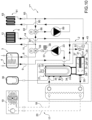
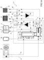
- reference numeral 1 indicates as a whole a heat pump system for room heating and for the production of domestic hot water.
- the system 1 comprises a heat pump 2 and a hydraulic network 3 hydraulically connected to one another.
- the hydraulic network 3 comprises, in turn, in a known manner, a high-temperature heating circuit 5 and a circuit 4 for the production of domestic hot water.
- the circuit 4 comprises a hot water delivery duct 6 towards at least one heating element 7 and a cold water return duct 9 from the heating element 7 towards the heat pump 2.
- the circuit 5 comprises, in turn, a hot water delivery duct 11 towards at least one radiator 12 and a cold water return duct 14 towards the heat pump 2 from the radiator 12.
- the heat pump 2 comprises:
- the auxiliary heater 21 is provided with a number of electric resistances 32 for heating the water and is provided with an air relief valve 33, with a tap 34 for discharging the water which, in case of need, sends the water to be discharged through a discharge duct; a safety valve 35 which, in case of need, is designed to send the water to be discharged through a discharge duct; and an expansion tank 36.
- the heat pump 2 comprises a flow meter 37 which detects the flow of water circulating in the system, a pressure switch 38, and a three-way diverter valve 39 designed to activate the domestic step and/or the heating step by diverting the water flow coming from the pumping assembly 23.
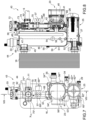
- the pumping assembly 23 comprises, in turn, an electric motor 40 which sets in rotation an impeller 41 which, in turn, is enclosed in a pump body 42 (or screw) illustrated in Figure 8 .
- the heat pump system 1 comprises a hydraulic valve assembly 43 designed to regulate the water flows from/to the heat exchanger 16 and from/to the hydraulic network 3.
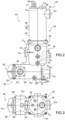
- the hydraulic assembly 43 is made by means of a support body 44 comprising a tubular-shaped upper portion 45 which defines, at least partially, a housing of the auxiliary heater 21.
- the upper portion 45 is provided with a side wall 46 with cylindrical symmetry around an axis X 45 and a head wall 47.
- the upper portion 45 is provided with a union 48 for the heat exchanger 16 having an axis X 48 transverse (preferably orthogonal) to the axis X 45 and arranged on the side wall 46, in proximity to the head wall 47.
- the upper portion 45 is provided with a union 49 for the air relief valve 33 having an axis X 49 parallel to (and preferably non-coinciding with) the axis X 45 and arranged on the head wall 47.
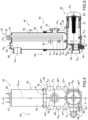
- the support body 44 further comprises a housing made by means of a tubular-shaped lower portion 50 which defines, together with the upper portion 45, the housing of the auxiliary heater 21.
- the lower portion 50 is provided with a side wall 51 with cylindrical symmetry around the axis X 45 and a bottom wall 52.
- the lower portion 50 is provided with a union 53 for the pumping assembly 23 having an axis X 53 transverse (preferably orthogonal) to the axis X 45 and arranged on the side wall 51, in proximity to the bottom wall 52.
- the lower portion 50 is provided with a pair of unions 54*, 54** diametrically opposite with respect to the axis X 45 for the safety valve 35 having a common axis X 54 orthogonal to the axis X 45 and to the axis X 53 and formed on the side wall 51, in proximity to a flange 55 for the connection with the upper portion 45.
- the lower portion 50 is provided with a pair of unions 56*, 56** diametrically opposite with respect to the axis X 45 for the expansion tank 36 having a common axis X 56 orthogonal to the axis X 45 and parallel to the axis X 54 and formed on the side wall 51, below the unions 54.
- the lower portion 50 is finally provided with a pair of unions 57*, 57** diametrically opposite with respect to the axis X 45 for the tap 34, having a common axis X 57 orthogonal to the axis X 45 and parallel to the axis X 54 and arranged on the side wall 51, below the unions 56, in proximity to the bottom wall 52.
- the upper and lower portions 45, 50 are connected to one another in a known manner (for example by welding or by attachment means at the flange 55).
- the particular embodiment of the auxiliary heater 21, whose main body is made by means of the connection of the upper portion 45 to the lower portion 50, allows adapting to the dimensions of any type of heat exchanger 16 by varying (increasing/reducing) the longitudinal extension of the upper portion 45.
- the housing of the auxiliary heater 21 is manufactured as one single body having a side wall with cylindrical symmetry around the axis X 45 , a bottom wall and a head wall.
- the support body 44 further comprises a tubular-shaped body 58 which defines the housing of the filtering element 25.
- the body 58 is provided with a side wall 59 with cylindrical symmetry around an axis X 59 , orthogonal to the axis X 45 and a pair of end walls 60, 61.
- the body 58 is provided with a pair of diametrically opposite unions 62*, 62** for the tap 29 having a common axis X 62 orthogonal to the axis X 59 and arranged on the side wall 59.
- the body 58 is provided with a union 63 for the shut-off valve 30 having an axis X 63 parallel to (and preferably non-coinciding with) the axis X 59 and orthogonal to the axis X 62 and arranged on the end wall 61.
- the union 63 is designed to accommodate a shut-off ball with suitable sealing gaskets.
- a sleeve 64 is fitted on the union 63 which defines the union for the heat exchanger 16 coaxial to the axis X 63 with the interposition of the shut-off valve 30.
- the body 58 is provided with a pair of unions 65*, 65** diametrically opposite with respect to the axis X 59 for the return ducts 9, 14 with the interposition of the shut-off valve 31 having a common axis X 65 orthogonal to the axis X 59 and parallel to the axis X 62 and formed on the side wall 59.
- the body 58 is manufactured as one single piece with the lower portion 50.
- the pump body 42 is connected to the union 53 and is provided with a lower appendage 66 for resting against the side wall 59. Furthermore, the pump body 42 is provided with an upper union 67, opposite to the appendage 66 and having an axis X 67 , which is arranged, in use, parallel to the axis X 45 and is designed to implement the connection with a manifold 68.
- the manifold 68 is made as a tubular body with cylindrical symmetry around the axis X 67 and is provided with a pair of unions 69*, 69**, arranged at the same height as the tubular body and having respective axes orthogonal to one another for implementing the connection with the flow meter 37 and the pressure switch 38, respectively.
- the manifold 68 defines at one end a union 70 for a support body 71 of the three-way diverter valve 39 designed to divert the water flow and having an electric motor 72, which in turn drives a relative diverter shutter 73 subjected to the action of a helical spring 74.
- the support body 71 further comprises a pair of unions 75*, 75** diametrically opposite with respect to the axis X 67 for the delivery duct 11 having a common axis X 75 orthogonal to the axis X 67 .
- the support body 71 comprises a union 92 for the delivery duct 6 having an axis X 92 orthogonal both to the axis X 67 and to the axis X 75 .
- the hydraulic assembly 43 comprises a connection bracket 93 interposed between the side wall defining the manifold 68 and the side wall 46.
- the heat pump system 1* for room heating and for the production of domestic hot water is of the glycol water/water type; the heat pump system 1* is alternative to the system illustrated in Figure 1 and the corresponding parts are indicated, where possible, with the same reference numerals.
- the system 1* is not provided with the heat exchanger 16; but it is rather provided with a glycol water supply circuit 76 comprising a glycol water delivery duct 77 towards the auxiliary heater 21 from a storage tank 78 and a glycol water return duct 79 from the filtering element 25 towards a storage tank 80.
- the union 48 is designed to implement the connection with the delivery duct 79 and the union, on the other hand, is designed to implement the connection with the return duct 77.
- the heat pump system 1** illustrated in Figure 10 is an alternative to the systems 1, 1* illustrated in Figures 1 and 9 and the corresponding parts are indicated, where possible, with the same reference numerals.
- the hydraulic network 3 comprises a low-temperature heating circuit 81 comprising a hot water delivery duct 82 towards at least one heating element 83 and a cold water return duct 85 from the heating element 83 towards the heat pump 2.
- the system 1** comprises a duct which supplies water from the three-way diverter valve 39 to a three-way mixing valve 88 and a pumping assembly 89 hydraulically connected to the three-way mixing valve 88 and to the delivery duct 82.
- system 1** comprises a return duct 90 from the low-temperature heating circuit 81 to the three-way mixing valve 88.
- system 1** comprises a pair of unidirectional valves 91, arranged upstream of the shut-off valve 31 along the return duct 85 and along the return ducts 9, 14.
- the union 75* is connected to a sleeve 94 coaxial to the axis X 75 which defines at one end a union having an axis orthogonal to the axis X 75 for a support body 95 of the three-way mixing valve 88 and having an electric motor 96, which in turn drives a relative diverter shutter subjected to the action of a helical spring.
- the support body 95 is provided with a further union 97 coaxial to the axis X 75 for the return duct 90 and a union having an axis orthogonal to the axis X 75 for a duct 98 connecting the three-way mixing valve 88 to the pumping assembly 89.
- the pumping assembly 89 comprises, in turn, an electric motor which sets in rotation an impeller enclosed in a pump body 99 (or screw).
- the pump body 99 is provided with an upper union 100 having an axis X 100 which is arranged, in use, parallel to the axis X 67 for the delivery duct 82.
- the shut-off valve 31 is made by means of a T-shaped body designed to accommodate a shut-off ball with suitable sealing gaskets and the two unidirectional valves 91 having a common axis X 91 .
- the heat pump system 1*** for room heating and for the production of domestic hot water is of the glycol water/water type; the heat pump system 1*** is alternative to the systems 1, 1*, 1** illustrated in Figures 1 , 9 and 10 and the corresponding parts are indicated, where possible, with the same reference numerals.
- the system 1*** is not provided with the heat exchanger 16; but it is provided with a glycol water supply circuit 76 comprising a duct 77 for delivering glycol water to the auxiliary heater 21 from a storage tank 78 and a duct 79 for returning glycol water from the filtering element 25 to a storage tank 80.
- the union 48 is designed to implement the connection with the delivery duct 79 and the union 30, on the other hand, is designed to implement the connection with the return duct 77.
- both the support body 44 and the manifold 38 can be provided with further unions in addition to those listed and possibly closed by means of suitable closing caps.
- the hydraulic assembly 43 described thus far is hydraulically connected directly to the heat exchanger 16 through quick couplings.
- the main advantage of the hydraulic assembly 43 consists in providing a rational arrangement of the components of the heat pump system 1 and a consequent reduction of the overall dimensions thanks to the reduction of the pipes necessary for the connection of said components.
- the particular construction of the support body 44 allows a significant reduction in investment costs in moulds and equipment and a consequent reduction in manufacturing costs.
Landscapes
- Engineering & Computer Science (AREA)
- Physics & Mathematics (AREA)
- Thermal Sciences (AREA)
- Chemical & Material Sciences (AREA)
- Combustion & Propulsion (AREA)
- Mechanical Engineering (AREA)
- General Engineering & Computer Science (AREA)
- Steam Or Hot-Water Central Heating Systems (AREA)
- Heat-Pump Type And Storage Water Heaters (AREA)
- Central Heating Systems (AREA)
- Domestic Hot-Water Supply Systems And Details Of Heating Systems (AREA)
Claims (18)
- Ensemble hydraulique (43) pour un système de pompe à chaleur (1, 1*, 1**, 1***) pour le chauffage de locaux et pour la production d'eau chaude sanitaire, dans lequel une pompe à chaleur (2) est connectée hydrauliquement à un réseau hydraulique (3) ayant un circuit de chauffage de locaux (5) et un circuit de chauffage d'eau chaude sanitaire (4) ; la pompe à chaleur (2) est pourvue d'un échangeur de chaleur (16), d'un élément de chauffage auxiliaire (21) en connexion hydraulique avec l'échangeur de chaleur (16) et pourvu d'un certain nombre de résistances électriques (32) agencées à l'intérieur d'un boîtier, et d'un élément filtrant (25) en connexion hydraulique avec l'échangeur de chaleur (16) pour les impuretés libérées dans l'eau et ayant un réservoir (26) extérieur ; dans lequel l'ensemble hydraulique (43) peut être connecté hydrauliquement à l'échangeur de chaleur (16) de manière directe, et comprend un corps de support (44) comprenant une première partie (45) et une deuxième partie (58) ; dans lequel la première partie (45) définit au moins partiellement ledit boîtier, a un premier axe (X45) et est pourvue d'un premier raccord (48) pour la connexion à l'échangeur de chaleur (16) ; la deuxième partie (58) comprend un corps ayant un deuxième axe (X58) orthogonal au premier axe (X45), qui définit ledit réservoir (26), et est pourvue d'un deuxième raccord (63) pour la connexion à l'échangeur de chaleur (16) ;
l'ensemble hydraulique (43) est caractérisé en ce que le corps de support (44) est en outre pourvu :- d'un troisième raccord (49) ayant un troisième axe (X49) pour la connexion à une soupape de décharge d'air (33) ; et/ou- d'une paire de quatrièmes raccords (54) ayant un quatrième axe (X54) commun pour une soupape de sécurité (35) ; et/ou- une paire de cinquièmes raccords (56) ayant un cinquième axe (X56) commun pour un réservoir d'expansion (36) ; et/ou- une paire de sixièmes raccords (57) ayant un sixième axe (X57) commun pour un robinet (34). - Ensemble selon la revendication 1, dans lequel le corps de support (44) comprend une troisième partie (50) coaxiale au premier axe (X45) et fabriquée en un seul tenant avec la deuxième partie (58), qui définit avec la première partie (45) à laquelle elle est connectée ledit boîtier de l'élément de chauffage auxiliaire (21).
- Ensemble selon la revendication 1 ou 2, dans lequel les premier et deuxième raccords (48, 63) sont pourvus d'un septième axe (X45) et d'un huitième axe (X63), respectivement, qui sont parallèles l'un à l'autre et qui sont tous deux transversaux, de préférence orthogonaux au premier axe (X45).
- Ensemble selon l'une des revendications précédentes, dans lequel la pompe à chaleur (2) est pourvue d'un premier ensemble de pompage (23) connecté hydrauliquement à l'élément de chauffage auxiliaire (21) ; et dans lequel le corps de support (44) est pourvu d'un septième raccord (53) ayant un neuvième axe (X53) respectif, qui est transversal, de préférence orthogonal, au premier axe (X45).
- Ensemble selon les revendications 3 et 4, dans lequel le septième raccord (53) est diamétralement opposé par rapport aux premier et deuxième raccords (48, 63).
- Ensemble selon l'une des revendications précédentes, dans lequel lesdits troisième raccord (49), quatrièmes raccords (54), cinquièmes raccords (56) et sixièmes raccords (57) sont obtenus dans la troisième partie (50) ou dans la première partie (45).
- Ensemble selon l'une des revendications précédentes, dans lequel le troisième axe (X49) est parallèle au premier axe (X45) et de préférence ne coïncide pas avec celui-ci ; et/ou dans lequel le quatrième axe (X54), le cinquième axe (X56) et le sixième axe (X57) sont transversaux, de préférence orthogonaux, au premier axe (X45).
- Ensemble selon l'une des revendications précédentes, dans lequel la deuxième partie (58) est pourvue d'une paire de huitièmes raccords (62*, 62**) diamétralement opposés pour un robinet (29).
- Ensemble selon l'une des revendications précédentes, dans lequel la pompe à chaleur (2) comprend une première soupape d'arrêt (30) de débit d'eau interposée entre l'échangeur de chaleur (16) et l'élément filtrant (25) ; et une deuxième soupape d'arrêt (31) de débit agencée immédiatement en amont de l'élément filtrant (25) ; et dans lequel la deuxième partie (58) est pourvue de neuvièmes raccords (63) respectifs pour la première soupape d'arrêt (30) et pour la deuxième soupape d'arrêt (31) ayant des axes respectifs qui sont orthogonaux l'un par rapport à l'autre.
- Ensemble selon l'une des revendications précédentes, dans lequel la pompe à chaleur (2) est pourvue d'un premier ensemble de pompage (23) connecté hydrauliquement à l'élément de chauffage auxiliaire (21) ; et l'ensemble hydraulique (43) comprend un collecteur (68) ayant une forme tubulaire et pourvu d'un dixième axe (X67) agencé, en cours d'utilisation, parallèlement au premier axe (X45), et peut être connecté à un dixième raccord (67) d'un corps de pompe (42) du premier ensemble de pompage (23).
- Ensemble selon la revendication 10, dans lequel le collecteur (68) est pourvu d'une paire de onzièmes raccords (69*, 69**) ayant des axes orthogonaux respectifs de sorte à établir une connexion à un débitmètre (37) et à un commutateur de pression (38), respectivement.
- Ensemble selon la revendication 10 ou 11, dans lequel
le collecteur (68) est connecté à un corps de support (71) d'une soupape de dérivation à trois voies (39) coaxiale au dixième axe (X67) et ayant une pluralité de deux douzièmes raccords (75, 92) pour un conduit de distribution (11) du circuit secondaire (5) et pour un conduit de distribution (6) du circuit primaire (4). - Ensemble selon l'une des revendications de 10 à 12, dans lequel l'ensemble hydraulique (43) comprend un support de connexion (93) interposé entre le collecteur (68) et une paroi latérale (46) de la première partie (45).
- Pompe à chaleur (2), caractérisée en ce qu'elle est pourvue d'au moins un ensemble hydraulique (43) selon l'une des revendications de 1 à 13.
- Pompe à chaleur selon la revendication 14, comprenant une soupape d'arrêt (31) de débit agencée immédiatement en amont de l'élément filtrant (25) ; et une paire de soupapes unidirectionnelles (91) agencées en amont de la soupape d'arrêt (31) ; dans laquelle ladite soupape d'arrêt (31) est obtenue au moyen d'un corps en forme de T conçu pour recevoir une bille d'arrêt, et les deux soupapes unidirectionnelles (91) ayant un axe (X91) commun.
- Pompe à chaleur selon la revendication 14 ou 15, dans laquelle
le premier ensemble de pompage (23) a un corps de pompe (42) pourvu d'un appendice inférieur (66) contre lequel repose une paroi (59) latérale de la deuxième partie (58). - Pompe à chaleur selon l'une des revendications de 14 à 16, dans laquelle le réseau hydraulique (3) comprend un circuit de chauffage à basse température (81) et la pompe à chaleur (2) est pourvue d'un mitigeur à trois voies (88) et d'un deuxième ensemble de pompage (89) connecté hydrauliquement au mitigeur à trois voies (88) ; dans laquelle le mitigeur à trois voies (88) a un corps de support (95) pourvu de raccords respectifs pour un conduit de retour (90) et pour un conduit de connexion (98) pour la connexion au deuxième ensemble de pompage (89) et à la soupape de dérivation à trois voies (39).
- Pompe à chaleur selon la revendication 17, dans laquelle le deuxième ensemble de pompage (89) est pourvu d'un corps de pompe (99) pourvu d'un raccord supérieur (100) pour un conduit de distribution (82) du circuit de chauffage à basse température (81).
Applications Claiming Priority (1)
| Application Number | Priority Date | Filing Date | Title |
|---|---|---|---|
| IT102019000019874A IT201900019874A1 (it) | 2019-10-28 | 2019-10-28 | Gruppo idraulico per una pompa di calore per il riscaldamento di ambienti e/o per la produzione di acqua calda sanitaria e pompa di calore provvista di tale gruppo |
Publications (2)
| Publication Number | Publication Date |
|---|---|
| EP3816521A1 EP3816521A1 (fr) | 2021-05-05 |
| EP3816521B1 true EP3816521B1 (fr) | 2023-10-18 |
Family
ID=69743792
Family Applications (1)
| Application Number | Title | Priority Date | Filing Date |
|---|---|---|---|
| EP20204477.2A Active EP3816521B1 (fr) | 2019-10-28 | 2020-10-28 | Ensemble hydraulique pour une pompe à chaleur pour le chauffage des pièces et pour la production d'eau chaude domestique et de pompe à chaleur fourni avec dit ensemble |
Country Status (4)
| Country | Link |
|---|---|
| EP (1) | EP3816521B1 (fr) |
| ES (1) | ES2967011T3 (fr) |
| IT (1) | IT201900019874A1 (fr) |
| PL (1) | PL3816521T3 (fr) |
Families Citing this family (4)
| Publication number | Priority date | Publication date | Assignee | Title |
|---|---|---|---|---|
| SK9474Y1 (sk) | 2021-06-13 | 2022-04-13 | Protherm Production S.R.O. | Hydraulický modul pre vykurovacie zariadenie s tepelným čerpadlom |
| CN120604087A (zh) * | 2023-01-31 | 2025-09-05 | 格兰富控股公司 | 用于热泵的集成水回路 |
| DE102023128874A1 (de) * | 2023-10-20 | 2025-04-24 | Stiebel Eltron Gmbh & Co. Kg | Haustechnik-Heizeinheit |
| EP4614076A1 (fr) * | 2024-03-07 | 2025-09-10 | OTMA S.r.l. con unico socio | Ensemble hydraulique pour une pompe à chaleur pour le chauffage de locaux et/ou pour la production d'eau chaude sanitaire et pompe à chaleur équipée de cet ensemble |
Family Cites Families (5)
| Publication number | Priority date | Publication date | Assignee | Title |
|---|---|---|---|---|
| CH538076A (de) * | 1972-05-05 | 1973-06-15 | Lins Albert | Steuereinrichtung für eine Zentralheizungsanlage |
| US4924069A (en) * | 1987-11-19 | 1990-05-08 | Teledyne Industries, Inc. | Hot water supply for tubs |
| DK2942583T3 (da) * | 2014-05-06 | 2017-11-20 | O T M A S N C Di Spaggiari & C | En bloc-støttelegeme til en hydraulisk ventilgruppe til anvendelse i en vægmonteret kedel |
| FR3043174B1 (fr) * | 2015-10-29 | 2017-10-20 | Paul Emile Ivars | Systeme de chauffage et dispositif de production d'eau chaude sanitaire et de chauffage incorporant ledit systeme de chauffage |
| IT201700022780A1 (it) * | 2017-03-01 | 2018-09-01 | O T M A S N C Di Spaggiari & C | Corpo di supporto monoblocco per un gruppo idraulico valvolare utilizzato in una caldaia |
-
2019
- 2019-10-28 IT IT102019000019874A patent/IT201900019874A1/it unknown
-
2020
- 2020-10-28 PL PL20204477.2T patent/PL3816521T3/pl unknown
- 2020-10-28 ES ES20204477T patent/ES2967011T3/es active Active
- 2020-10-28 EP EP20204477.2A patent/EP3816521B1/fr active Active
Also Published As
| Publication number | Publication date |
|---|---|
| IT201900019874A1 (it) | 2021-04-28 |
| PL3816521T3 (pl) | 2024-04-08 |
| EP3816521A1 (fr) | 2021-05-05 |
| ES2967011T3 (es) | 2024-04-25 |
Similar Documents
| Publication | Publication Date | Title |
|---|---|---|
| EP3816521B1 (fr) | Ensemble hydraulique pour une pompe à chaleur pour le chauffage des pièces et pour la production d'eau chaude domestique et de pompe à chaleur fourni avec dit ensemble | |
| EP2833072B1 (fr) | Chauffage et système d'alimentation en eau chaude | |
| EP4108996A1 (fr) | Station de chaleur modulaire | |
| WO2017122028A1 (fr) | Vanne d'entretien et de maintenance de chaudière | |
| EP2148149A2 (fr) | Ensemble de vanne hydraulique pour chaudières à montage mural | |
| EP3370011B1 (fr) | Corps multifonction monobloc pour un ensemble soupape hydraulique utilisé dans une centrale combinée | |
| EP4108998A1 (fr) | Station de chauffage monolithique avec dérivation | |
| US11988395B2 (en) | Thermal energy extraction assembly | |
| EP3680574B1 (fr) | Groupe hydraulique | |
| EP4107447A1 (fr) | Système de climatisation centralisé | |
| EP4614076A1 (fr) | Ensemble hydraulique pour une pompe à chaleur pour le chauffage de locaux et/ou pour la production d'eau chaude sanitaire et pompe à chaleur équipée de cet ensemble | |
| JP2017180945A (ja) | 貯湯式給湯機 | |
| EP4108997A1 (fr) | Dispositif d'interconnexion pour station de chauffage | |
| EP3084316B1 (fr) | Appareil échangeur de chaleur | |
| EP2362154B1 (fr) | Unité de distribution creuse monobloc pour systèmes de chauffage | |
| CN219141171U (zh) | 一种采暖提温式热泵以及供暖系统 | |
| EP4194767B1 (fr) | Cumulus instantané de liquides pour la consommation humaine et/ou pour des liquides alimentaires | |
| CN108050697A (zh) | 多功能热水器水罐及供水系统 | |
| US12173932B2 (en) | Valve | |
| CN101799083A (zh) | 带有旁路的全封闭式三通阀 | |
| GB2459893A (en) | Water heating system | |
| WO2024188425A1 (fr) | Kit de cadre de pompe à chaleur hybride doté d'une partie de réception | |
| CN208567177U (zh) | 一种节水节能的太阳能供水器 | |
| CN207081198U (zh) | 带外置加热装置的储水式电热水器 | |
| WO2024188423A1 (fr) | Kit de cadre de pompe à chaleur hybride |
Legal Events
| Date | Code | Title | Description |
|---|---|---|---|
| PUAI | Public reference made under article 153(3) epc to a published international application that has entered the european phase |
Free format text: ORIGINAL CODE: 0009012 |
|
| STAA | Information on the status of an ep patent application or granted ep patent |
Free format text: STATUS: THE APPLICATION HAS BEEN PUBLISHED |
|
| AK | Designated contracting states |
Kind code of ref document: A1 Designated state(s): AL AT BE BG CH CY CZ DE DK EE ES FI FR GB GR HR HU IE IS IT LI LT LU LV MC MK MT NL NO PL PT RO RS SE SI SK SM TR |
|
| STAA | Information on the status of an ep patent application or granted ep patent |
Free format text: STATUS: REQUEST FOR EXAMINATION WAS MADE |
|
| 17P | Request for examination filed |
Effective date: 20210913 |
|
| RBV | Designated contracting states (corrected) |
Designated state(s): AL AT BE BG CH CY CZ DE DK EE ES FI FR GB GR HR HU IE IS IT LI LT LU LV MC MK MT NL NO PL PT RO RS SE SI SK SM TR |
|
| GRAP | Despatch of communication of intention to grant a patent |
Free format text: ORIGINAL CODE: EPIDOSNIGR1 |
|
| STAA | Information on the status of an ep patent application or granted ep patent |
Free format text: STATUS: GRANT OF PATENT IS INTENDED |
|
| INTG | Intention to grant announced |
Effective date: 20230508 |
|
| P01 | Opt-out of the competence of the unified patent court (upc) registered |
Effective date: 20230511 |
|
| GRAS | Grant fee paid |
Free format text: ORIGINAL CODE: EPIDOSNIGR3 |
|
| GRAA | (expected) grant |
Free format text: ORIGINAL CODE: 0009210 |
|
| STAA | Information on the status of an ep patent application or granted ep patent |
Free format text: STATUS: THE PATENT HAS BEEN GRANTED |
|
| AK | Designated contracting states |
Kind code of ref document: B1 Designated state(s): AL AT BE BG CH CY CZ DE DK EE ES FI FR GB GR HR HU IE IS IT LI LT LU LV MC MK MT NL NO PL PT RO RS SE SI SK SM TR |
|
| REG | Reference to a national code |
Ref country code: GB Ref legal event code: FG4D |
|
| REG | Reference to a national code |
Ref country code: CH Ref legal event code: EP |
|
| REG | Reference to a national code |
Ref country code: IE Ref legal event code: FG4D |
|
| REG | Reference to a national code |
Ref country code: DE Ref legal event code: R096 Ref document number: 602020019372 Country of ref document: DE |
|
| REG | Reference to a national code |
Ref country code: LT Ref legal event code: MG9D |
|
| REG | Reference to a national code |
Ref country code: NL Ref legal event code: MP Effective date: 20231018 |
|
| REG | Reference to a national code |
Ref country code: AT Ref legal event code: MK05 Ref document number: 1622766 Country of ref document: AT Kind code of ref document: T Effective date: 20231018 |
|
| PG25 | Lapsed in a contracting state [announced via postgrant information from national office to epo] |
Ref country code: NL Free format text: LAPSE BECAUSE OF FAILURE TO SUBMIT A TRANSLATION OF THE DESCRIPTION OR TO PAY THE FEE WITHIN THE PRESCRIBED TIME-LIMIT Effective date: 20231018 |
|
| PG25 | Lapsed in a contracting state [announced via postgrant information from national office to epo] |
Ref country code: GR Free format text: LAPSE BECAUSE OF FAILURE TO SUBMIT A TRANSLATION OF THE DESCRIPTION OR TO PAY THE FEE WITHIN THE PRESCRIBED TIME-LIMIT Effective date: 20240119 |
|
| PG25 | Lapsed in a contracting state [announced via postgrant information from national office to epo] |
Ref country code: IS Free format text: LAPSE BECAUSE OF FAILURE TO SUBMIT A TRANSLATION OF THE DESCRIPTION OR TO PAY THE FEE WITHIN THE PRESCRIBED TIME-LIMIT Effective date: 20240218 |
|
| PG25 | Lapsed in a contracting state [announced via postgrant information from national office to epo] |
Ref country code: LT Free format text: LAPSE BECAUSE OF FAILURE TO SUBMIT A TRANSLATION OF THE DESCRIPTION OR TO PAY THE FEE WITHIN THE PRESCRIBED TIME-LIMIT Effective date: 20231018 |
|
| PG25 | Lapsed in a contracting state [announced via postgrant information from national office to epo] |
Ref country code: AT Free format text: LAPSE BECAUSE OF FAILURE TO SUBMIT A TRANSLATION OF THE DESCRIPTION OR TO PAY THE FEE WITHIN THE PRESCRIBED TIME-LIMIT Effective date: 20231018 |
|
| REG | Reference to a national code |
Ref country code: ES Ref legal event code: FG2A Ref document number: 2967011 Country of ref document: ES Kind code of ref document: T3 Effective date: 20240425 |
|
| PG25 | Lapsed in a contracting state [announced via postgrant information from national office to epo] |
Ref country code: LT Free format text: LAPSE BECAUSE OF FAILURE TO SUBMIT A TRANSLATION OF THE DESCRIPTION OR TO PAY THE FEE WITHIN THE PRESCRIBED TIME-LIMIT Effective date: 20231018 Ref country code: IT Free format text: LAPSE BECAUSE OF NON-PAYMENT OF DUE FEES Effective date: 20231028 Ref country code: IS Free format text: LAPSE BECAUSE OF FAILURE TO SUBMIT A TRANSLATION OF THE DESCRIPTION OR TO PAY THE FEE WITHIN THE PRESCRIBED TIME-LIMIT Effective date: 20240218 Ref country code: GR Free format text: LAPSE BECAUSE OF FAILURE TO SUBMIT A TRANSLATION OF THE DESCRIPTION OR TO PAY THE FEE WITHIN THE PRESCRIBED TIME-LIMIT Effective date: 20240119 Ref country code: BG Free format text: LAPSE BECAUSE OF FAILURE TO SUBMIT A TRANSLATION OF THE DESCRIPTION OR TO PAY THE FEE WITHIN THE PRESCRIBED TIME-LIMIT Effective date: 20240118 Ref country code: AT Free format text: LAPSE BECAUSE OF FAILURE TO SUBMIT A TRANSLATION OF THE DESCRIPTION OR TO PAY THE FEE WITHIN THE PRESCRIBED TIME-LIMIT Effective date: 20231018 Ref country code: PT Free format text: LAPSE BECAUSE OF FAILURE TO SUBMIT A TRANSLATION OF THE DESCRIPTION OR TO PAY THE FEE WITHIN THE PRESCRIBED TIME-LIMIT Effective date: 20240219 |
|
| PG25 | Lapsed in a contracting state [announced via postgrant information from national office to epo] |
Ref country code: SE Free format text: LAPSE BECAUSE OF FAILURE TO SUBMIT A TRANSLATION OF THE DESCRIPTION OR TO PAY THE FEE WITHIN THE PRESCRIBED TIME-LIMIT Effective date: 20231018 Ref country code: RS Free format text: LAPSE BECAUSE OF FAILURE TO SUBMIT A TRANSLATION OF THE DESCRIPTION OR TO PAY THE FEE WITHIN THE PRESCRIBED TIME-LIMIT Effective date: 20231018 Ref country code: NO Free format text: LAPSE BECAUSE OF FAILURE TO SUBMIT A TRANSLATION OF THE DESCRIPTION OR TO PAY THE FEE WITHIN THE PRESCRIBED TIME-LIMIT Effective date: 20240118 Ref country code: LV Free format text: LAPSE BECAUSE OF FAILURE TO SUBMIT A TRANSLATION OF THE DESCRIPTION OR TO PAY THE FEE WITHIN THE PRESCRIBED TIME-LIMIT Effective date: 20231018 Ref country code: HR Free format text: LAPSE BECAUSE OF FAILURE TO SUBMIT A TRANSLATION OF THE DESCRIPTION OR TO PAY THE FEE WITHIN THE PRESCRIBED TIME-LIMIT Effective date: 20231018 |
|
| REG | Reference to a national code |
Ref country code: CH Ref legal event code: PL |
|
| REG | Reference to a national code |
Ref country code: BE Ref legal event code: MM Effective date: 20231031 |
|
| PG25 | Lapsed in a contracting state [announced via postgrant information from national office to epo] |
Ref country code: LU Free format text: LAPSE BECAUSE OF NON-PAYMENT OF DUE FEES Effective date: 20231028 |
|
| PG25 | Lapsed in a contracting state [announced via postgrant information from national office to epo] |
Ref country code: LU Free format text: LAPSE BECAUSE OF NON-PAYMENT OF DUE FEES Effective date: 20231028 |
|
| PG25 | Lapsed in a contracting state [announced via postgrant information from national office to epo] |
Ref country code: DK Free format text: LAPSE BECAUSE OF FAILURE TO SUBMIT A TRANSLATION OF THE DESCRIPTION OR TO PAY THE FEE WITHIN THE PRESCRIBED TIME-LIMIT Effective date: 20231018 |
|
| PG25 | Lapsed in a contracting state [announced via postgrant information from national office to epo] |
Ref country code: CH Free format text: LAPSE BECAUSE OF NON-PAYMENT OF DUE FEES Effective date: 20231031 |
|
| REG | Reference to a national code |
Ref country code: DE Ref legal event code: R097 Ref document number: 602020019372 Country of ref document: DE |
|
| PG25 | Lapsed in a contracting state [announced via postgrant information from national office to epo] |
Ref country code: CZ Free format text: LAPSE BECAUSE OF FAILURE TO SUBMIT A TRANSLATION OF THE DESCRIPTION OR TO PAY THE FEE WITHIN THE PRESCRIBED TIME-LIMIT Effective date: 20231018 |
|
| PG25 | Lapsed in a contracting state [announced via postgrant information from national office to epo] |
Ref country code: SK Free format text: LAPSE BECAUSE OF FAILURE TO SUBMIT A TRANSLATION OF THE DESCRIPTION OR TO PAY THE FEE WITHIN THE PRESCRIBED TIME-LIMIT Effective date: 20231018 |
|
| PG25 | Lapsed in a contracting state [announced via postgrant information from national office to epo] |
Ref country code: SM Free format text: LAPSE BECAUSE OF FAILURE TO SUBMIT A TRANSLATION OF THE DESCRIPTION OR TO PAY THE FEE WITHIN THE PRESCRIBED TIME-LIMIT Effective date: 20231018 Ref country code: SK Free format text: LAPSE BECAUSE OF FAILURE TO SUBMIT A TRANSLATION OF THE DESCRIPTION OR TO PAY THE FEE WITHIN THE PRESCRIBED TIME-LIMIT Effective date: 20231018 Ref country code: RO Free format text: LAPSE BECAUSE OF FAILURE TO SUBMIT A TRANSLATION OF THE DESCRIPTION OR TO PAY THE FEE WITHIN THE PRESCRIBED TIME-LIMIT Effective date: 20231018 Ref country code: EE Free format text: LAPSE BECAUSE OF FAILURE TO SUBMIT A TRANSLATION OF THE DESCRIPTION OR TO PAY THE FEE WITHIN THE PRESCRIBED TIME-LIMIT Effective date: 20231018 Ref country code: DK Free format text: LAPSE BECAUSE OF FAILURE TO SUBMIT A TRANSLATION OF THE DESCRIPTION OR TO PAY THE FEE WITHIN THE PRESCRIBED TIME-LIMIT Effective date: 20231018 Ref country code: CZ Free format text: LAPSE BECAUSE OF FAILURE TO SUBMIT A TRANSLATION OF THE DESCRIPTION OR TO PAY THE FEE WITHIN THE PRESCRIBED TIME-LIMIT Effective date: 20231018 Ref country code: CH Free format text: LAPSE BECAUSE OF NON-PAYMENT OF DUE FEES Effective date: 20231031 |
|
| PLBE | No opposition filed within time limit |
Free format text: ORIGINAL CODE: 0009261 |
|
| STAA | Information on the status of an ep patent application or granted ep patent |
Free format text: STATUS: NO OPPOSITION FILED WITHIN TIME LIMIT |
|
| PG25 | Lapsed in a contracting state [announced via postgrant information from national office to epo] |
Ref country code: MC Free format text: LAPSE BECAUSE OF FAILURE TO SUBMIT A TRANSLATION OF THE DESCRIPTION OR TO PAY THE FEE WITHIN THE PRESCRIBED TIME-LIMIT Effective date: 20231018 |
|
| PG25 | Lapsed in a contracting state [announced via postgrant information from national office to epo] |
Ref country code: MC Free format text: LAPSE BECAUSE OF FAILURE TO SUBMIT A TRANSLATION OF THE DESCRIPTION OR TO PAY THE FEE WITHIN THE PRESCRIBED TIME-LIMIT Effective date: 20231018 Ref country code: BE Free format text: LAPSE BECAUSE OF NON-PAYMENT OF DUE FEES Effective date: 20231031 |
|
| 26N | No opposition filed |
Effective date: 20240719 |
|
| PG25 | Lapsed in a contracting state [announced via postgrant information from national office to epo] |
Ref country code: IE Free format text: LAPSE BECAUSE OF NON-PAYMENT OF DUE FEES Effective date: 20231028 |
|
| PG25 | Lapsed in a contracting state [announced via postgrant information from national office to epo] |
Ref country code: SI Free format text: LAPSE BECAUSE OF FAILURE TO SUBMIT A TRANSLATION OF THE DESCRIPTION OR TO PAY THE FEE WITHIN THE PRESCRIBED TIME-LIMIT Effective date: 20231018 |
|
| PG25 | Lapsed in a contracting state [announced via postgrant information from national office to epo] |
Ref country code: SI Free format text: LAPSE BECAUSE OF FAILURE TO SUBMIT A TRANSLATION OF THE DESCRIPTION OR TO PAY THE FEE WITHIN THE PRESCRIBED TIME-LIMIT Effective date: 20231018 Ref country code: IE Free format text: LAPSE BECAUSE OF NON-PAYMENT OF DUE FEES Effective date: 20231028 |
|
| PG25 | Lapsed in a contracting state [announced via postgrant information from national office to epo] |
Ref country code: IT Free format text: LAPSE BECAUSE OF NON-PAYMENT OF DUE FEES Effective date: 20231028 |
|
| PGRI | Patent reinstated in contracting state [announced from national office to epo] |
Ref country code: IT Effective date: 20231031 |
|
| PG25 | Lapsed in a contracting state [announced via postgrant information from national office to epo] |
Ref country code: IT Free format text: LAPSE BECAUSE OF NON-PAYMENT OF DUE FEES Effective date: 20231028 |
|
| PGRI | Patent reinstated in contracting state [announced from national office to epo] |
Ref country code: IT Effective date: 20231031 |
|
| PG25 | Lapsed in a contracting state [announced via postgrant information from national office to epo] |
Ref country code: FI Free format text: LAPSE BECAUSE OF FAILURE TO SUBMIT A TRANSLATION OF THE DESCRIPTION OR TO PAY THE FEE WITHIN THE PRESCRIBED TIME-LIMIT Effective date: 20231019 |
|
| PG25 | Lapsed in a contracting state [announced via postgrant information from national office to epo] |
Ref country code: CY Free format text: LAPSE BECAUSE OF FAILURE TO SUBMIT A TRANSLATION OF THE DESCRIPTION OR TO PAY THE FEE WITHIN THE PRESCRIBED TIME-LIMIT; INVALID AB INITIO Effective date: 20201028 |
|
| PG25 | Lapsed in a contracting state [announced via postgrant information from national office to epo] |
Ref country code: HU Free format text: LAPSE BECAUSE OF FAILURE TO SUBMIT A TRANSLATION OF THE DESCRIPTION OR TO PAY THE FEE WITHIN THE PRESCRIBED TIME-LIMIT; INVALID AB INITIO Effective date: 20201028 |
|
| PGFP | Annual fee paid to national office [announced via postgrant information from national office to epo] |
Ref country code: DE Payment date: 20251028 Year of fee payment: 6 |
|
| PGFP | Annual fee paid to national office [announced via postgrant information from national office to epo] |
Ref country code: GB Payment date: 20251023 Year of fee payment: 6 |
|
| PGFP | Annual fee paid to national office [announced via postgrant information from national office to epo] |
Ref country code: IT Payment date: 20251006 Year of fee payment: 6 |
|
| PGFP | Annual fee paid to national office [announced via postgrant information from national office to epo] |
Ref country code: FR Payment date: 20251027 Year of fee payment: 6 |
|
| PGFP | Annual fee paid to national office [announced via postgrant information from national office to epo] |
Ref country code: TR Payment date: 20251008 Year of fee payment: 6 |
|
| PGFP | Annual fee paid to national office [announced via postgrant information from national office to epo] |
Ref country code: PL Payment date: 20251010 Year of fee payment: 6 |
|
| PGFP | Annual fee paid to national office [announced via postgrant information from national office to epo] |
Ref country code: ES Payment date: 20251118 Year of fee payment: 6 |