EP3816657B1 - Mehrstrahlmessvorrichtung zur 3d-abtastung einer umgebung mit nahtlos gestapelten empfangsmodulen - Google Patents
Mehrstrahlmessvorrichtung zur 3d-abtastung einer umgebung mit nahtlos gestapelten empfangsmodulen Download PDFInfo
- Publication number
- EP3816657B1 EP3816657B1 EP19205917.8A EP19205917A EP3816657B1 EP 3816657 B1 EP3816657 B1 EP 3816657B1 EP 19205917 A EP19205917 A EP 19205917A EP 3816657 B1 EP3816657 B1 EP 3816657B1
- Authority
- EP
- European Patent Office
- Prior art keywords
- receiver
- laser
- arrays
- array
- measurement device
- Prior art date
- Legal status (The legal status is an assumption and is not a legal conclusion. Google has not performed a legal analysis and makes no representation as to the accuracy of the status listed.)
- Active
Links
Images


Classifications
-
- G—PHYSICS
- G01—MEASURING; TESTING
- G01S—RADIO DIRECTION-FINDING; RADIO NAVIGATION; DETERMINING DISTANCE OR VELOCITY BY USE OF RADIO WAVES; LOCATING OR PRESENCE-DETECTING BY USE OF THE REFLECTION OR RERADIATION OF RADIO WAVES; ANALOGOUS ARRANGEMENTS USING OTHER WAVES
- G01S17/00—Systems using the reflection or reradiation of electromagnetic waves other than radio waves, e.g. lidar systems
- G01S17/02—Systems using the reflection of electromagnetic waves other than radio waves
- G01S17/06—Systems determining position data of a target
- G01S17/08—Systems determining position data of a target for measuring distance only
- G01S17/10—Systems determining position data of a target for measuring distance only using transmission of interrupted, pulse-modulated waves
-
- G—PHYSICS
- G01—MEASURING; TESTING
- G01C—MEASURING DISTANCES, LEVELS OR BEARINGS; SURVEYING; NAVIGATION; GYROSCOPIC INSTRUMENTS; PHOTOGRAMMETRY OR VIDEOGRAMMETRY
- G01C15/00—Surveying instruments or accessories not provided for in groups G01C1/00 - G01C13/00
- G01C15/002—Active optical surveying means
-
- G—PHYSICS
- G01—MEASURING; TESTING
- G01S—RADIO DIRECTION-FINDING; RADIO NAVIGATION; DETERMINING DISTANCE OR VELOCITY BY USE OF RADIO WAVES; LOCATING OR PRESENCE-DETECTING BY USE OF THE REFLECTION OR RERADIATION OF RADIO WAVES; ANALOGOUS ARRANGEMENTS USING OTHER WAVES
- G01S17/00—Systems using the reflection or reradiation of electromagnetic waves other than radio waves, e.g. lidar systems
- G01S17/02—Systems using the reflection of electromagnetic waves other than radio waves
- G01S17/06—Systems determining position data of a target
- G01S17/42—Simultaneous measurement of distance and other co-ordinates
-
- G—PHYSICS
- G01—MEASURING; TESTING
- G01S—RADIO DIRECTION-FINDING; RADIO NAVIGATION; DETERMINING DISTANCE OR VELOCITY BY USE OF RADIO WAVES; LOCATING OR PRESENCE-DETECTING BY USE OF THE REFLECTION OR RERADIATION OF RADIO WAVES; ANALOGOUS ARRANGEMENTS USING OTHER WAVES
- G01S17/00—Systems using the reflection or reradiation of electromagnetic waves other than radio waves, e.g. lidar systems
- G01S17/88—Lidar systems specially adapted for specific applications
- G01S17/89—Lidar systems specially adapted for specific applications for mapping or imaging
-
- G—PHYSICS
- G01—MEASURING; TESTING
- G01S—RADIO DIRECTION-FINDING; RADIO NAVIGATION; DETERMINING DISTANCE OR VELOCITY BY USE OF RADIO WAVES; LOCATING OR PRESENCE-DETECTING BY USE OF THE REFLECTION OR RERADIATION OF RADIO WAVES; ANALOGOUS ARRANGEMENTS USING OTHER WAVES
- G01S17/00—Systems using the reflection or reradiation of electromagnetic waves other than radio waves, e.g. lidar systems
- G01S17/88—Lidar systems specially adapted for specific applications
- G01S17/93—Lidar systems specially adapted for specific applications for anti-collision purposes
- G01S17/931—Lidar systems specially adapted for specific applications for anti-collision purposes of land vehicles
-
- G—PHYSICS
- G01—MEASURING; TESTING
- G01S—RADIO DIRECTION-FINDING; RADIO NAVIGATION; DETERMINING DISTANCE OR VELOCITY BY USE OF RADIO WAVES; LOCATING OR PRESENCE-DETECTING BY USE OF THE REFLECTION OR RERADIATION OF RADIO WAVES; ANALOGOUS ARRANGEMENTS USING OTHER WAVES
- G01S7/00—Details of systems according to groups G01S13/00, G01S15/00, G01S17/00
- G01S7/48—Details of systems according to groups G01S13/00, G01S15/00, G01S17/00 of systems according to group G01S17/00
- G01S7/481—Constructional features, e.g. arrangements of optical elements
- G01S7/4814—Constructional features, e.g. arrangements of optical elements of transmitters alone
- G01S7/4815—Constructional features, e.g. arrangements of optical elements of transmitters alone using multiple transmitters
-
- G—PHYSICS
- G01—MEASURING; TESTING
- G01S—RADIO DIRECTION-FINDING; RADIO NAVIGATION; DETERMINING DISTANCE OR VELOCITY BY USE OF RADIO WAVES; LOCATING OR PRESENCE-DETECTING BY USE OF THE REFLECTION OR RERADIATION OF RADIO WAVES; ANALOGOUS ARRANGEMENTS USING OTHER WAVES
- G01S7/00—Details of systems according to groups G01S13/00, G01S15/00, G01S17/00
- G01S7/48—Details of systems according to groups G01S13/00, G01S15/00, G01S17/00 of systems according to group G01S17/00
- G01S7/481—Constructional features, e.g. arrangements of optical elements
- G01S7/4816—Constructional features, e.g. arrangements of optical elements of receivers alone
-
- G—PHYSICS
- G01—MEASURING; TESTING
- G01S—RADIO DIRECTION-FINDING; RADIO NAVIGATION; DETERMINING DISTANCE OR VELOCITY BY USE OF RADIO WAVES; LOCATING OR PRESENCE-DETECTING BY USE OF THE REFLECTION OR RERADIATION OF RADIO WAVES; ANALOGOUS ARRANGEMENTS USING OTHER WAVES
- G01S7/00—Details of systems according to groups G01S13/00, G01S15/00, G01S17/00
- G01S7/48—Details of systems according to groups G01S13/00, G01S15/00, G01S17/00 of systems according to group G01S17/00
- G01S7/483—Details of pulse systems
- G01S7/484—Transmitters
-
- G—PHYSICS
- G01—MEASURING; TESTING
- G01S—RADIO DIRECTION-FINDING; RADIO NAVIGATION; DETERMINING DISTANCE OR VELOCITY BY USE OF RADIO WAVES; LOCATING OR PRESENCE-DETECTING BY USE OF THE REFLECTION OR RERADIATION OF RADIO WAVES; ANALOGOUS ARRANGEMENTS USING OTHER WAVES
- G01S7/00—Details of systems according to groups G01S13/00, G01S15/00, G01S17/00
- G01S7/48—Details of systems according to groups G01S13/00, G01S15/00, G01S17/00 of systems according to group G01S17/00
- G01S7/483—Details of pulse systems
- G01S7/486—Receivers
- G01S7/4865—Time delay measurement, e.g. time-of-flight measurement, time of arrival measurement or determining the exact position of a peak
-
- G—PHYSICS
- G01—MEASURING; TESTING
- G01S—RADIO DIRECTION-FINDING; RADIO NAVIGATION; DETERMINING DISTANCE OR VELOCITY BY USE OF RADIO WAVES; LOCATING OR PRESENCE-DETECTING BY USE OF THE REFLECTION OR RERADIATION OF RADIO WAVES; ANALOGOUS ARRANGEMENTS USING OTHER WAVES
- G01S7/00—Details of systems according to groups G01S13/00, G01S15/00, G01S17/00
- G01S7/48—Details of systems according to groups G01S13/00, G01S15/00, G01S17/00 of systems according to group G01S17/00
- G01S7/497—Means for monitoring or calibrating
Definitions
- the present invention relates to a measurement device for the three-dimensional geometric capture of an environment by means of a plurality of transmission beams.
- Such measurement devices may be used in the fields of mobile mapping, surveying, or autonomous driving, and are known from, for instance, US 2018/364334 A1 , US 2019/235058 A1 and WO 2018/121009 A1 .
- the devices are mounted on vehicles, backpacks or drones, e.g. unmanned ground vehicles (UGVs) or unmanned aerial vehicles (UAVs), to measure the environment or to detect obstacles.
- the measurement devices may be used in a static assembly, e.g. to monitor certain areas (surveillance) or to measure, detect, count or classify objects moving past the measuring device, such as workpieces on a conveyor belt or motor vehicles on the highway.
- Scanning objects or surfaces in surroundings is carried out by means of a distance measurement beam, e.g. a directional pulsed laser beam, wherein the spatial position of a surface point is determined from the measured distance to the targeted surface point and angle information providing the direction of the distance measurement beam.
- Typical measurement devices are able to move, e.g. rotate, one or multiple distance measurement beams to different pointing directions, wherein individual measurement directions and associated distances are linked with one another to generate a so-called 3D point cloud.
- Such 3D scanning is a very effective technology for producing millions of individual measurement points, in particular 3D coordinates, within minutes or seconds.
- an image recording is additionally carried out by a camera, providing not only the visual overall view but also further information, e.g. with respect to the surface texture.
- 3D point cloud acquisition can also be carried out during a spatial movement of the measurement device, wherein the own movement of the measurement device is taken into account, e.g. by means of a global satellite positioning system (GSNS, "global navigation satellite system"), an inertial measuring system (IMU, "inertial measuring unit”), and/or by means of simultaneous position determination and mapping (SLAM, "Simultaneous Localization and Mapping").
- GSNS global satellite positioning system
- IMU inertial measuring system
- SLAM simultaneous position determination and mapping
- One approach consists in emitting pulsed electromagnetic radiation, such as e.g. laser light, at a target to be measured and subsequently receiving an echo from said target as backscattering object, wherein the distance to the target to be measured can be determined for example on the basis of the time of flight, the shape, and/or the phase of the pulse.
- pulsed electromagnetic radiation such as e.g. laser light
- Such laser distance measuring devices have in the meantime gained acceptance as standard solutions in many fields.
- Multi-beam measurement devices have various advantages, e.g. the provision of a higher point rate or a higher point density even with a slower rotational speed of a transmitter unit, no need of mechanical beam deflection, and the provision of a homogenous point distribution at the measurement object.
- individual partial beams of jointly emitted laser beams have to be aligned with corresponding reception regions.
- interfering crosstalks can occur between individual reception beams, wherein a specific reception region corresponding to a first beam detects light of a second beam emitted near the first beam.
- the distance measurement accuracy is limited.
- various measures are known, e.g. reducing the scanning density, beam masking, e.g. by means of the use of LCDs, or complicated optical arrangements in order to precisely align a plurality of emitter-detector pairings.
- the high (e.g. vertical) number of measuring points is achieved by a discrete arrangement of individual electronic boards or transmitter modules.
- a single laser transmitter is placed on its own board with associated control electronics.
- the high number of points is achieved by arranging several such boards.
- the same effort is required by arranging a single photodetector, e.g. an avalanche photodiode (APD) or a silicon photomultiplier (SiPM) with a corresponding read-out electronics on a circuit board and arranging a corresponding number of such boards to achieve the high point resolution.
- APD avalanche photodiode
- SiPM silicon photomultiplier
- the invention relates to a measurement device for the three-dimensional geometric capture of an environment, comprising a base and a rotating member comprising a transmission unit and a receiver unit, the rotating member being rotatable relative to the base about an axis of rotation and configured to rotate a beam exit area of the transmission unit and a beam entry area of the receiver unit about the axis of rotation, wherein the device further comprises an angle determining unit configured to determine angular data relating to the angular orientation of the rotating member about the axis of rotation.
- the rotating member rotates with a frequency between 10 Hz to 200 Hz.
- the transmission unit is configured to emit a plurality of transmission beams via the beam exit area, wherein transmission beams of the plurality of transmission beams are respectively emitted at different elevation angles with respect to the axis of rotation.
- the receiver unit is configured to detect transmission beams returning via the beam entry area and to generate distance measurement data relating to the plurality of transmission beams.
- the measurement device comprises a computing unit configured to derive three-dimensional point cloud data by combining the angle data, the distance measurement data, and stored directional data providing the beam direction of each of the plurality of transmission beams relative to the rotating member.
- the transmission unit comprises multiple receiver arrays arranged on separate array packages, wherein each receiver array comprises multiple receiving surfaces arranged along a respective receiver array axis for separately capturing individual transmission beams.
- each receiver array comprises multiple receiving surfaces arranged along a respective receiver array axis for separately capturing individual transmission beams.
- the individual receiving surfaces of their respective receiver array are tightly packed next to each other such that they define an oblong shape of the respective receiver array, which has an oblong extension along the respective receiver array axis.
- the extension of the receiver surface free array package area e.g.
- the separate array packages are shifted from one another and/or rotated with respect to each other such that the receiving surfaces are arranged in an oblong receiver section, wherein, measured along a longitudinal axis of the oblong receiver section, the receiving surfaces are arranged in a seamless fashion, namely, measured along the longitudinal axis of the receiver section, the gaps between adjoining receiving surfaces within the oblong receiver section are less than or equal to the gaps between receiving surfaces that belong to the same receiver array.
- the separate receiver packages are shifted from one another and/or rotated with respect to each other, e.g. wherein the packages have a horizontal offset to each other, such that at least in one direction the arrays can be stacked without additional spacing (the resulting parallax or different angle in the object space compared to a purely linear alignment in the other, e.g. the horizontal, direction is negligible or compensated through the rotation of the device).
- this provides for reduced manufacturing and set-up costs because only the complete arrays need to be aligned, rather than every single emitter.
- At least two of the receiver array axes are aligned parallel to each other, e.g. wherein the parallel axes are parallel to the longitudinal axis of the oblong receiver section, more particularly wherein the longitudinal axis of the oblong receiver section is parallel to the axis of rotation.
- the receiver array axes are horizontally offset to each other.
- the receiver arrays are embodied as avalanche photodiode (APD) or silicon photomultiplier (SiPM) arrays, in which a plurality of detection elements are produced from a monolithic silicon block.
- APD avalanche photodiode
- SiPM silicon photomultiplier
- the photolithographic processes used in semiconductor fabrication allow APD arrays or SiPM arrays to be manufactured with a high reproducible accuracy with respect to the spacing of the components from each other (e.g. 100 ⁇ m, 250 ⁇ m, 500 ⁇ m).
- the number of elements of an array is limited.
- the higher the number of elements (APD's or SiPM) on an array the smaller the yield of optimally functioning arrays. Consequently, since at both ends of the array arrangement additional space is required for the package (housing), the electronics, or for sawing the electronics chip, sequencing several such arrays inevitably leads to gaps.
- the detector arrays are embodied as avalanche photodiode arrays, each avalanche photodiode representing one of the multiple receiving surfaces.
- each receiver array is based on a sensor configured to provide different, e.g. pre-defined selectable or dynamically settable, acquisition regions on the same detection surface, such that the different acquisition regions are used as different receiving surfaces.
- the receiver unit comprises an objective lens, which is shared by the multiple receiver arrays.
- each of the receiver arrays comprises its own objective lens.
- the transmission unit comprises multiple laser arrays, each laser array being associated to one of the multiple receiver arrays (or to a set of receiver arrays) and comprising multiple laser emitters arranged along a respective laser array axis, wherein the transmission unit is configured that transmission beams generated by respective laser arrays are detected by the receiver surfaces of their associated receiver array.
- the transmission unit is configured that, based on each laser array, a corresponding set of transmission beams is generated, wherein the angular difference in elevation angle of adjacent transmission beams within a respective set of transmission beams is less than or equal to a maximum angular difference, wherein the combination of the sets of transmission beams of two laser arrays forms an arrangement of transmission beams, wherein the angular difference in elevation angle of adjacent transmission beams within the arrangement of transmission beams is less than or equal to the maximum angular difference (associated to an individual set of transmission beams).
- the laser array comprises multiple laser emitters made from a monolithic silicon block allowing to produce arrays with high reproducible accuracy with respect to the gap between emitters (e.g. 100 ⁇ m, 250 ⁇ m, 500 ⁇ m).
- the number of emitters on such an array is typically limited, e.g. wherein the higher the number of emitters, the smaller the yield of optimally functioning arrays.
- currently laser arrays typically have eight emitters. Therefore, multiple such laser arrays are necessary to reach a high point density or resolution, respectively.
- an optical beam splitting component such as a diffractive optical element (DOE), configured to split an incoming beam into a defined number of outgoing beams having well-defined angular separations with respect to each other, wherein the gap is "filled” by the multiplication of the beams by the DOE.
- DOE diffractive optical element
- the transmission unit comprises an optical beam splitting component arranged in the optical path associated to at least part of the multiple laser arrays and configured to split an incoming beam generated by a respective laser emitter into a defined number of outgoing beams having well-defined angular separations with respect to each other, e.g. wherein the optical beam splitting component comprises at least one of a diffractive optical element, a diffraction grating, e.g. a Dammann grating, and a holographic optical element.
- the optical beam splitting component comprises at least one of a diffractive optical element, a diffraction grating, e.g. a Dammann grating, and a holographic optical element.
- a diffraction grating may be used such that for each individual laser beam passing through the grating the first four diffraction maxima will generate four beams emitted at well-defined angles.
- the multiple laser arrays are arranged on separate array packages, which are shifted from another and/or rotated with respect to each other such that the laser emitters are arranged in an oblong emitter section, wherein, measured along a longitudinal axis of the oblong emitter section, the laser emitters are arranged in a seamless fashion, namely, measured along the longitudinal axis of the emitter section, the gaps between adjoining laser emitters within the oblong emitter section are less than or equal to the gaps between laser emitters that belong to the same laser array.
- the packages have a horizontal offset to each other, such that at least in one direction the arrays can be stacked without additional spacing (the resulting parallax or respectively different angle in the object space compared to a purely linear alignment in the other, e.g. the horizontal, direction is negligible or compensated through the rotation of the device).
- this provides for reduced manufacturing and set-up costs because only the complete arrays need to be aligned, rather than every single emitter.
- the transmission unit comprises an objective lens, which is shared by the multiple laser arrays, e.g. wherein the transmission unit is configured to provide an elevation field of view of at least 10°.
- each laser array comprises its own objective lens, e.g. wherein the transmission unit is configured to provide an elevation field of view of at least 40°.
- the receiver unit and/or the transmission unit comprises a zoom component configured to compensate a focal length mismatch between the receiver unit and the transmission unit, e.g. to adjust focal length tolerances of the receiver unit relative to focal length tolerances of the transmission unit relating to the optical beam splitting component.
- the focal length manufacturing tolerances of the transmission unit have to match with angles of the optical beam splitting component and the pitch of the laser arrays.
- the laser arrays and/or the receiver arrays are arranged along respective arcs defined by the image field curvature caused by the transmitting optics or the receiving optics, respectively.
- the arrays are assigned to different tangents of the corresponding arc and respective receiver array axes or respective laser array axes are arranged parallel their assigned tangents.
- each laser array may be configured that its laser emitters are individually controlled, particularly wherein the transmission unit is configured that each laser array is controlled by its own laser pulser.
- the measurement device is configured that in each of the multiple laser arrays the respective laser emitters are sequentially activated, and in each of the multiple laser arrays at least two immediately adjacent laser emitters are assigned to the same receiving surface, which, for example, has a double-keyhole shaped aperture.
- the beams generated by the two immediately adjacent laser emitters are detected by the same receiving surface, e.g. the same avalanche photodiode.
- the total number of different beams associated to different elevations can be larger than the number of individual receiving surfaces.
- each laser array comprises eight laser diodes
- the optical beam splitting component is arranged in a common optical path section of the multiple laser arrays and configured to split a respective incoming beam into at least two, particularly at least four, outgoing beams
- each receiver array comprises eight, particularly sixteen, receiving surfaces.
- sixteen beams are generated, each beam being associated with a different elevation, wherein the returning beams are detected by eight individual receiving surfaces, i.e. an individual receiver surface sequentially receives two sequentially emitted laser beams.
- the measurement device comprises an optical component, which is shared by the transmission unit and the receiver unit.
- the shared component is a common objective, this is typically referred to as so-called coaxial design.
- all the optics of the transmission unit are separated from the optics of the receiver unit, which is also referred to as so-called biaxial design.
- the (e.g. vertical) spatial resolution may be increased by at least one of the following measures: at least part of the laser arrays being tilted towards the direction of rotation of the rotating member about the axis of rotation; the laser arrays being arranged with respect to each other that, measured along the longitudinal axis of the oblong emitter section, the laser emitters of two different laser arrays are arranged in an interleaving fashion; the receiver arrays being arranged with respect to each other that, measured along the longitudinal axis of the oblong receiver section, the receiving surfaces of two different receiver arrays are arranged in an interleaving fashion; and at least part of the receiver arrays being tilted towards the direction of rotation of the rotating member about the axis of rotation.
- optical components may be arranged in the optical transmission and/or reception path to correct influences such as beam deflection, blur, and/or aberration of a lighthouse encasing the transmission unit and the receiver unit.
- Another aspect of the invention relates to the transfer of data and energy between the rotating member and the base.
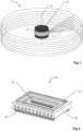
- Figure 1 shows an outer view of an exemplary measurement device 1, formed with a base and a rotating member (not shown, see Fig. 5 ) arranged rotatably on the base about a rotation axis 2 relative to the base.
- the rotating member is enclosed by a protective housing 3, which is fixed to the base and has a circumferential window 4 allowing the transmitted and the returning radiation to pass.
- the protective housing 3 could also be configured to rotate with the rotating member.
- the protective housing may be dustproof and/or waterproof (IP65), wherein the measurement device is configured to compensate for beam deflections of the transmitted and received beams caused by the circumferential window 4.
- the measurement device 1 is configured to generate a plurality of transmission beams for transmitting pulsed distance measuring radiation, wherein different elevations can be scanned by different transmission beams.
- the elevation here refers to an angle to the axis of rotation 2, typically measured from a ground plane orthogonal to the axis of rotation 2. With exactly vertical alignment of the axis of rotation 2, as shown in the figure, the elevation thus corresponds to a certain distance of height above ground.
- the measurement device 1 can be arranged in any orientation to the ground.
- the elevation in a horizontal orientation of the axis of rotation 2 corresponds to an angle to the rotation axis measured from a vertical plane.
- the plurality of transmission beams thus defines a fan 5 of distance measuring beams rotating about the rotation axis 2 (lying in a vertical plane).
- a circumferential field of view (field of the scanning area) may be generated, e.g. of 360 ° x 25 °, by rotating the fan 5 about the rotation axis 2.
- a partial field of view e.g. 80 ° x 25 ° may be scanned by oscillating the fan 5 back and forth or by only generating coordinate measuring data for a particular observation window, e.g. a particular azimuthal range.
- the measurement device can also be configured to provide an extension of the vertical field of view by tilting the rotating member with respect to the rotation axis 2.
- the plurality of transmission beams is generated by means of a plurality of laser arrays (see below).
- Returning distance measuring beams of the different transmission beams entering a receiver objective unit are directed, e.g. in a straight or angled fashion, to a plurality of receiver arrays (see below), e.g. based on semiconductor photomultiplier sensors (SPM sensors) or avalanche photo diodes (APD) configured for distance measurements.
- SPM sensors semiconductor photomultiplier sensors
- APD avalanche photo diodes
- the rotating member comprises a computing unit configured to derive a three-dimensional point cloud based on angle data providing the angular orientation of the rotating member about the rotation axis 2, the distance measurement data, and stored directional data providing the beam direction of each of the plurality of transmission beams.
- the computing unit can also be arranged statically, e.g. in the base.
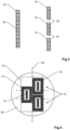
- Figure 2 shows a schematic representation of a receiver array 6.
- the receiver array 6 is embodied as APD array comprising a plurality of closely stacked APDs 9 arranged in a housing with corresponding connectors 10.
- the housing further comprises a protection window 11, e.g. to protect the APDs 9 and the electronics from dust and/or humidity.
- a keyhole shaped aperture can be applied on the protection window or on the surface of the APD array.
- a laser bar of a certain number of laser diodes e.g. eight laser diodes, may be used, wherein the laser diodes and corresponding connectors are typically arranged on an insulator substrate.
- each laser diode has three stacked active emission zones.
- the width of the emission zones of pulse laser diodes is typically between 70 ⁇ m and 350 ⁇ m.
- a very narrow emission zone e.g. 70 ⁇ m
- a cylindrical rod lens is placed close to the emission strip, also known as fast axis collimation (FAC) lens, e.g. to reduce the divergence of the laser beam in the fast axis-direction, to reduce the transverse emission angle and to symmetrize the beam profile.
- FAC fast axis collimation
- the higher the number of elements on an array the smaller the yield of optimally functioning arrays.
- suitable laser arrays are not available with more than eight elements and suitable receiver arrays are limited to about 24 elements. Therefore, for producing a distance measuring unit with many laser emitters to achieve a high density of points stacking of several laser and receiver arrays is required.
- the receiver array is installed in an electronics package and thus, as depicted on the right of Fig. 3 , only interrupted receiver lines can be generated, i.e. wherein the receiving surface free package area inevitably leads to gaps 15 in the scan pattern.
- Homogeneous scanning of the object to be measured can be achieved by arranging the arrays 6 according to the invention, by shifting and/or rotating the arrays 6 with respect to each other, such that at least in one direction the arrays 6 are stacked without additional spacing.
- FIG. 4 One example is depicted by figure 4 showing a frontal view onto an inventive arrangement of three receiver arrays 6.
- the receiver arrays 6 are embodied as shown by Fig. 2 .
- the receiver arrays 6 are arranged along a longitudinal axis 16 of an oblong receiver section 17, wherein one of the receiver arrays is horizontally displaced with respect to the other two. Therefore, measured along the longitudinal axis 16 of the oblong receiver section 17, e.g. wherein the longitudinal axis is parallel to the vertical axis, the receiving surfaces 9 are arranged in a seamless fashion. In other words, measured along the longitudinal axis 16 the height difference (e.g. in the vertical direction) between two successive receiving surfaces within the oblong receiving section 17 corresponds to the pitch or spacing between adjacent receiving surfaces 9 within the receiver arrays 6.
- the receiver arrays 6 are aligned with the help of micromanipulators on the plane on which the arrays are located and then glued or soldered to a common electronics board 18.
- the electronic board 18 is then installed and aligned in the rotating member (see below).
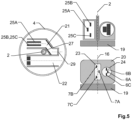
- Figure 5 schematically depicts the measurement device in a top view on the left, from behind on the top right, and up front in the bottom right.
- the axis of rotation 2 is defined by a hollow shaft (see Fig. 9 ), extending from the base 19 along the axis of rotation into the rotating member 20.
- the rotating member 20 comprises a transmission optical path 21 and a reception optical path 22.
- the rotating member is configured to rotate a beam exit area 23 of the transmission unit and a beam entry area 24 of the receiver unit about the axis of rotation 2.
- the transmission unit comprises three laser arrays 7A, 7B, 7C arranged on separate electronic boards 25A, 25B, 25C.
- the separate electronic boards 25A, 25B, 25C are arranged parallel with respect to each other such that the laser arrays 7A, 7B, 7C are arranged along a longitudinal axis 16 of an oblong emitter section.
- the gaps between the emitters of the laser arrays are filled by the multiplication of the beams of individual laser emitters by means of a diffractive optical element 29 (DOE) in order to generate a seamless scanning arrangement in the vertical direction.
- DOE diffractive optical element 29
- the laser arrays 7A, 7B, 7C share an objective unit, wherein, for example, the transmission optical path 21 is configured that the transmission beams are guided by mirrors 27 in such a way that the beam exit area 23 is arranged radially symmetric with respect to the axis of rotation 2.
- the receiving optical path 22 comprises three separately packed receiver arrays 6A, 6B, 6C arranged as described by Fig. 4 , wherein each receiver array is assigned to one of the three laser arrays 7A, 7B, 7C. Further, in the example shown the receiving optical path 22 comprises a common objective for all receiver arrays 6A, 6B, 6C.
- the pitch between the laser diodes of one laser array and the focal length of the transmission optical path 21 and the pitch between the receiving surfaces of the receiver arrays and the focal length of the receiving optical path as well as the angular spacing of the different beams of the DOE 29 have a well-defined relationship so that the angles of the transmission beams matches the angles of the receiver optics.
- the number of laser diodes per laser array as well as the number of receiver surfaces per receiver array as well as the total number of laser arrays and receiver arrays as well as the number of the different beams of the DOE have a well-defined relationship so that the numbers of transmission beams matches the number of receiving surfaces.
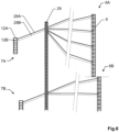
- Figure 6 schematically depicts the paths 28A,28B of laser beams emitted from different laser diodes 12A,12B of a laser array 7A, here comprising eight laser diodes.
- the laser beams are transmitting through a beam splitting component 29, e.g. a diffraction grating, traveling to a target, and being detected by a corresponding receiver array 6A.
- a beam splitting component 29 e.g. a diffraction grating
- each individual laser beam passing through the grating 29 is split into four beams emitted at well-defined angles based on the first four diffraction maxima.
- the optical beam splitting component 29 is arranged in a common optical path section of the laser arrays 7A,7B.
- the receiver array 6A comprises sixteen receiving surfaces (detection areas) 9, e.g. APDs.
- the measurement device is configured that in each of the multiple laser arrays 7A,7B the respective laser emitters are sequentially activated, and in each of the multiple laser arrays at least two immediately adjacent laser emitters 12A,12B are assigned to the same receiving surface, which, for example, has a double-keyhole shaped aperture for background light suppression.
- the beams generated by the two immediately adjacent laser emitters 12A,12B are detected by the same detection area, e.g. the same avalanche photodiode.
- the optical beam splitting component 29 multiplies the incoming beams with "small” angles, wherein the "large” angles are effected by arranging the laser arrays 7A,7B having a (here a vertical) gap between each other.
- the gap is "filled” by the beam multiplication due to the beam splitting component 29.
- a laser beam e.g. a laser beam at the top or bottom array along the vertical direction
- a laser beam at the top or bottom array along the vertical direction can be used for an internal optical reference path to allow calibration of the absolute distance. Because of choosing a marginal ray, the seamless manner of the spatial or angular spacing of the measurement beams is not interrupted.
- Figure 7 schematically depicts a further embodiment of the invention using a beam splitting component 29, wherein here, the beam splitting component multiplies the incoming beams with "large" angles.
- the laser arrays 7A,7B are arranged in a seamless manner, i.e. similarly as described above in Fig. 4 for the receiver side, wherein the complete bundle of beams of a respective laser array 7A,7B is multiplied.
- the beam splitting component 29 is a diffractive optical element and multiplies the beam bundles into three beam bundles based on the first three diffraction maxima, wherein the three beam bundles which are detected by three separate receiver arrays 60A, 61A, 62A, 60B, 61B, 62B respectively associated to the different laser arrays 7A,7B.
- Figure 8 schematically depicts a further embodiment of the invention using a beam splitting component 29, wherein here, the beam splitting component 29 effects a beam splitting at very small angles for generating an additional smaller angle than that predetermined by the pitch of the laser array 7A,7B. For example, this can be used to increase the resolution.
- this embodiment can additionally be combined with a transmitter-side seamless array arrangement.
- Figure 9 schematically depicts a further embodiment of the invention where interleaving or tilting of the laser arrays or the receiver arrays, respectively, is used to increase the spatial resolution.
- an interleaved arrangement of four receiver arrays 6 is shown, namely the upper left showing a side view and the upper right showing a front view.
- the resolution in the vertical direction i.e. in the orthogonal to the direction of rotation
- the resolution in the vertical direction is doubled.
- two of the receiver arrays 6 are tilted towards the direction of rotation 30 of the measurement device. This also leads to an increased vertical resolution.
- Figure 10 shows an aspect of the invention relating to the transfer of data and energy between the rotating member 100 and the static base 101.
- the figure shows a vertical cut through the rotation mechanics of the measurement device (without optical elements).
- the base 100 comprises a hollow shaft 102 defining the axis of rotation, the hollow shaft 102 extending along the axis of rotation into the rotating member 100, wherein the rotating member 100 is rotatable relative to the base 101 about the axis of rotation, i.e. about the hollow shaft 102.
- the embodiment further comprises an optical data transmission unit configured to provide wireless data exchange between the base 101 and the rotating member 100 by means of an optical signal 103.
- the optical data transmission unit comprises a data transmitter 104A, which may particularly be embodied as data transceiver, being mounted to the rotating member 100 such that it is located at one distal end of the shaft. Furthermore, a data receiver 104B, which may particularly be embodied as data transceiver, is mounted to the base 101 at the other distal end of the shaft 102.
- the data transmitter 104A and receiver 104B are configured and arranged to exchange data by an optical signal 103 propagating in a free-beam manner in the inside of the hollow shaft 102.
- the data transmitter 104A and receiver 104B may be embodied as data transceivers which allow to simultaneously send and receive data via the optical signal 103.
- the measurement device further comprises an inductive power exchange unit, configured to provide power exchange between the base 101 and the rotating member 100 and comprising a power transmitter 105A and a power receiver 105B.
- the power receiver 105B and the power transmitter 105A of the inductive power exchange unit are arranged about the hollow shaft 102 in an area axially displaced from the data transmitter 104A and receiver 104B, which reduces mutual interferences between the transmission unit and the power exchange unit.
Landscapes
- Engineering & Computer Science (AREA)
- Physics & Mathematics (AREA)
- General Physics & Mathematics (AREA)
- Radar, Positioning & Navigation (AREA)
- Remote Sensing (AREA)
- Computer Networks & Wireless Communication (AREA)
- Electromagnetism (AREA)
- Optical Radar Systems And Details Thereof (AREA)
- Photometry And Measurement Of Optical Pulse Characteristics (AREA)
- Length Measuring Devices By Optical Means (AREA)
Claims (13)
- Messvorrichtung (1) für das dreidimensionale geometrische Aufnehmen einer Umgebung, umfassend• eine Basis (19, 101),• ein Drehbauteil (20, 100), umfassend eine Übertragungseinheit und eine Empfängereinheit, wobei das Drehbauteil (20, 100) relativ zur Basis (19, 101) um eine Drehachse (2) drehbar und dazu konfiguriert ist, einen Strahlaustrittsbereich (23) der Übertragungseinheit und einen Strahleintrittsbereich (24) der Empfängereinheit um die Drehachse (2) zu drehen,• eine Winkelbestimmungseinheit, die dazu konfiguriert ist, Winkeldaten in Bezug auf die Winkelausrichtung des Drehbauteils (20, 100) um die Drehachse (2) zu bestimmen,• wobei die Übertragungseinheit dazu konfiguriert ist, eine Vielzahl von Übertragungsstrahlen über den Strahlaustrittsbereich (23) zu emittieren, wobei Übertragungsstrahlen der Vielzahl von Übertragungsstrahlen jeweils in unterschiedlichen Elevationswinkeln in Bezug auf die Drehachse (2) emittiert werden,• wobei die Empfängereinheit dazu konfiguriert ist, Übertragungsstrahlen, die über den Strahleintrittsbereich (24) zurückkehren, zu erkennen und Entfernungsmessungsdaten in Bezug auf die Vielzahl der Übertragungsstrahlen zu generieren, und• eine Recheneinheit, die dazu konfiguriert ist, dreidimensionale Punktwolkendaten durch Kombinieren der Winkeldaten, der Entfernungsmessungsdaten und der gespeicherten Richtungsdaten, die die Stahlrichtung jedes der Vielzahl von Übertragungsstrahlen relativ zu dem Drehbauteil bereitstellen, abzuleiten,
dadurch gekennzeichnet, dass• die Empfängereinheit mehrere Empfängerarrays (6, 6A, 6B, 6C, 60A, 61A, 62A, 60B, 61B, 62B) umfasst, die auf getrennten Arraypaketen (8) angeordnet sind, wobei jedes Empfängerarray mehrere Empfängerflächen (9) umfasst, die entlang einer jeweiligen Empfängerarrayachse zum getrennten Aufnehmen einzelner Übertragungsstrahlen angeordnet sind, wobei jedes Empfängerarray als Folgendes ausgebildet isto Lawinenphotodiode oder Silizium-Photovervielfacher-Array, umfassend eine Vielzahl von Erkennungselementen, die aus einem monolithischen Siliziumblock hergestellt und entlang der jeweiligen Empfängerarraysachse angeordnet sind, odero ein Sensor, der dazu konfiguriert ist, verschiedene Erfassungsregionen auf der gleichen Erkennungsfläche bereitzustellen, so dass die verschiedenen Erfassungsregionen als die verschiedenen Empfängerflächen (9) verwendet werden,wobei an beiden axialen Enden des Empfängerarrays (6, 6A, 6B, 6C, 60A, 61A, 62A, 60B, 61B, 62B), gemessen entlang der jeweiligen Empfängerarraysachse, die Ausdehnung des Arraypaketbereichs, welcher frei von Empfängerflächen ist, länger ist als die Lücken zwischen angrenzenden Empfängerflächen (9) innerhalb des jeweiligen Empfängerarrays (6, 6A, 6B, 6C, 60A, 61A, 62A, 60B, 61B, 62B), und• die getrennten Arraypakete (8) voneinander verschoben und/oder in Bezug aufeinander gedreht sind, so dass die Empfängerflächen (9) in einem länglichen Empfängerabschnitt (17) angeordnet sind, wobei, gemessen entlang einer Längsachse (16) des länglichen Empfängerabschnitts (17), die Empfängerflächen (9) in einer nahtlosen Weise angeordnet sind, nämlich so, dass, gemessen entlang der Längsachse (16) des Empfängerabschnitts (17), die Lücken zwischen angrenzenden Empfängerflächen (9) der angrenzenden Empfängerarrays (6, 6A, 6B, 6C, 60A, 61A, 62A, 60B, 61B, 62B) innerhalb des länglichen Empfängerabschnitts (17) kleiner oder gleich den Lücken zwischen den Empfängerflächen (9) sind, die zu dem gleichen Empfängerarray (6, 6A, 6B, 6C, 60A, 61A, 62A, 60B, 61B, 62B) gehören. - Messvorrichtung (1) nach Anspruch 1,
dadurch gekennzeichnet, dass
mindestens zwei der Empfängerarraysachsen parallel zueinander ausgerichtet sind, wobei die parallelen Achsen parallel zu der Längsachse (16) des länglichen Empfängerabschnitts (17) sind und wobei die Längsachse (16) des länglichen Empfängerabschnitts (17) parallel zu der Drehachse (2) ist. - Messvorrichtung (1) nach einem der vorhergehenden Ansprüche,
dadurch gekennzeichnet, dassdie Übertragungseinheit mehrere Laserarrays (7, 7A, 7B, 7C) umfasst, wobei jedes Laserarray mit einem der mehreren Empfängerarrays (6, 6A, 6B, 6C, 60A, 61A, 62A, 60B, 61B, 62B) assoziiert ist und mehrere Laseremitter (12A, 12B) umfasst, die entlang einer jeweiligen Laserarraysachse angeordnet sind, wobei die Übertragungseinheit so konfiguriert ist, dass Übertragungsstrahlen, die von den jeweiligen Laserarrays generiert werden, von den Empfängerflächen ihrer assoziierten Empfängerarrays erkannt werden,wobei die Übertragungseinheit so konfiguriert ist, dass, auf Grundlage jedes Laserarrays (7, 7A, 7B, 7C), ein entsprechender Satz Übertragungsstrahlen generiert wird, wobei der Winkelunterschied des Elevationswinkels von angrenzenden Übertragungsstrahlen innerhalb eines jeweiligen Satzes von Übertragungsstrahlen kleiner oder gleich einem maximalen Winkelunterschied ist, wobei die Kombination der Sätze von Übertragungsstrahlen von zwei Laserarrays eine Anordnung von Übertragungsstrahlen bildet, wobei der Winkelunterschied des Elevationswinkels von angrenzenden Übertragungsstrahlen innerhalb der Anordnung von Übertragungsstrahlen kleiner oder gleich dem maximalen Winkelunterschied ist. - Messvorrichtung (1) nach Anspruch 3,
dadurch gekennzeichnet, dassdie Übertragungseinheit eine optische Strahlteilerkomponente (29) umfasst, die in dem optischen Pfad, der mit mindestens einem Teil der mehreren Laserarrays (7, 7A, 7B, 7C) assoziiert ist, angeordnet und dazu konfiguriert ist, einen eingehenden Strahl (28A, 28B), der von einem jeweiligen Laseremitter (12A, 12B) generiert wurde, in eine festgelegte Anzahl von ausgehenden Strahlen, die gut definierte Winkelabstände in Bezug aufeinander aufweisen, zu teilen,insbesondere wobei die optische Strahlteilerkomponente (29) mindestens eines der Folgenden umfasst• ein beugendes optisches Element,• ein Beugungsgitter, insbesondere ein Dammannprofil, und• ein holografisches optisches Element. - Messvorrichtung (1) nach Anspruch 3 oder 4,
dadurch gekennzeichnet, dass
die mehreren Laserarrays (7, 7A, 7B, 7C) auf getrennten Arraypaketen angeordnet sind, die voneinander verschoben und/oder in Bezug aufeinander gedreht sind, so dass die Laseremitter (12A, 12B) in einem länglichen Emitterabschnitt angeordnet sind, wobei, gemessen entlang einer Längsachse des länglichen Emitterabschnitts, die Laseremitter in einer nahtlosen Weise angeordnet sind, nämlich so, dass, gemessen entlang der Längsachse des Emitterabschnitts, die Lücken zwischen angrenzenden Laseremittern innerhalb des länglichen Emitterabschnitts kleiner oder gleich den Lücken zwischen den Laseremittern sind, die zu dem gleichen Laserarray gehören. - Messvorrichtung (1) nach einem der Ansprüche 3 bis 5,
dadurch gekennzeichnet, dass• die Empfängereinheit eine Objektivlinse umfasst, die sich die mehreren Empfängerarrays (6, 6A, 6B, 6C, 60A, 61A, 62A, 60B, 61B, 62B) teilen, oder• jedes der Empfängerarrays (6, 6A, 6B, 6C, 60A, 61A, 62A, 60B, 61B, 62B) seine eigene Objektivlinse umfasst,
und/oder• die Übertragungseinheit eine Objektivlinse umfasst, die sich die mehreren Laserarrays (7, 7A, 7B, 7C) teilen, insbesondere wobei die Übertragungseinheit dazu konfiguriert ist, ein Elevationssichtsfeld von mindestens 10° bereitzustellen, oder• jedes Laserarray (7, 7A, 7B, 7C) seine eigene Objektivlinse umfasst, insbesondere wobei die Übertragungseinheit dazu konfiguriert ist, ein Elevationssichtsfeld von mindestens 40° bereitzustellen. - Messvorrichtung (1) nach einem der vorhergehenden Ansprüche,
dadurch gekennzeichnet, dass
die Empfängereinheit und/oder die Übertragungseinheit eine Zoomkomponente umfasst, die dazu konfiguriert ist, eine Brennweitendiskrepanz zwischen der Empfängereinheit und der Übertragungseinheit auszugleichen, insbesondere zum Anpassen von Brennweitentoleranzen der Empfängereinheit relativ zu Brennweitentoleranzen der Übertragungseinheit in Bezug auf die optische Strahlteilerkomponente (29). - Messvorrichtung (1) nach einem der Ansprüche 3-6,
dadurch gekennzeichnet, dass
die Laserarrays (7, 7A, 7B, 7C) und/oder Empfängerarrays (6, 6A, 6B, 6C, 60A, 61A, 62A, 60B, 61B, 62B) entlang jeweiliger Lichtbögen, die durch die Bildfeldkrümmung definiert sind, die von der Übertragungsoptik bzw. der Empfängeroptik verursacht wird, angeordnet sind, insbesondere wobei die Arrays (6, 6A, 6B, 6C, 60A, 61A, 62A, 60B, 61B, 62B, 7, 7A, 7B, 7C) verschiedenen Tangenten der entsprechenden Lichtbögen und jeweiligen Empfängerarrayachsen oder jeweiligen Laserarrayachsen, die parallel zu den ihnen zugeordneten Tangenten angeordnet sind, zugeordnet sind. - Messvorrichtung (1) nach einem der Ansprüche 3-6, 8,
dadurch gekennzeichnet, dass• jedes Laserarray (7, 7A, 7B, 7C) so konfiguriert ist, dass seine Laseremitter (12A, 12B) einzeln gesteuert werden, insbesondere wobei die Übertragungseinheit so konfiguriert ist, dass jedes Laserarray durch seinen eigenen Laserimpulsgeber gesteuert wird. - Messvorrichtung (1) nach einem der Ansprüche 3-6, 8-9,
dadurch gekennzeichnet, dass
die Messvorrichtung (1) so konfiguriert ist, dass• in jedem der mehreren Laserarrays (7, 7A, 7B, 7C) die jeweiligen Laseremitter (12A, 12B) nacheinander aktiviert werden, und• in jedem der mehreren Laserarrays mindestens zwei direkt angrenzende Laseremitter (12A, 12B) der gleichen Empfängerfläche zugeordnet sind, nämlich so, dass die Strahlen, die durch die mindestens zwei direkt angrenzenden Laseremitter (12A, 12B) generiert werden, durch die gleiche Empfängerfläche erkannt werden. - Messvorrichtung (1) nach einem der Ansprüche 3-6, 8-10,
dadurch gekennzeichnet, dass
jedes Laserarray (7, 7A, 7B, 7C) acht Laserdioden umfasst, wobei• die optische Strahlteilerkomponente (29) in einem gemeinsamen optischen Pfadabschnitt der mehreren Laserarrays angeordnet und dazu konfiguriert ist, einen jeweiligen eingehenden Strahl in mindestens zwei, insbesondere mindestens vier, ausgehende Strahlen zu teilen, und• jedes Empfängerarray (6, 6A, 6B, 6C, 60A, 61A, 62A, 60B, 61B, 62B) acht, insbesondere sechzehn, Empfängerflächen (9) umfasst. - Messvorrichtung (1) nach einem der vorhergehenden Ansprüche,
dadurch gekennzeichnet, dass• die Messvorrichtung eine optische Komponente umfasst, die sich die Übertragungseinheit und die Empfängereinheit teilen, oder• die gesamte Optik der Übertragungseinheit von der Optik der Empfängereinheit getrennt ist. - Messvorrichtung (1) nach einem der Ansprüche 3-6, 8-11,
dadurch gekennzeichnet, dass• mindestens ein Teil der Laserarrays zur Drehrichtung (30) des Drehbauteils (20, 100) um die Drehachse (2) geneigt ist,• die Laserarrays in Bezug aufeinander so angeordnet sind, dass, gemessen entlang der Längsachse des länglichen Emitterabschnitts, die Laseremitter von zwei verschiedenen Laserarrays in einer verschachtelten Weise angeordnet sind,• die Empfängerarrays in Bezug aufeinander so angeordnet sind, dass, gemessen entlang der Längsachse (16) des länglichen Empfängerabschnitts (17), die Empfängerflächen (9) von zwei verschiedenen Empfängerarrays in einer verschachtelten Weise angeordnet sind, und• mindestens ein Teil der Empfängerarrays zur Drehrichtung (30) des Drehbauteils (20, 100) um die Drehachse (2) geneigt ist.
Priority Applications (6)
| Application Number | Priority Date | Filing Date | Title |
|---|---|---|---|
| EP19205917.8A EP3816657B1 (de) | 2019-10-29 | 2019-10-29 | Mehrstrahlmessvorrichtung zur 3d-abtastung einer umgebung mit nahtlos gestapelten empfangsmodulen |
| EP20204461.6A EP3816661B1 (de) | 2019-10-29 | 2020-10-28 | Mehrstrahl-messvorrichtung zur 3d-abtastung einer umgebung mit mehreren halbleiterlaser-arrays und gleichförmiger strahlverteilung |
| EP25156762.4A EP4530678B1 (de) | 2019-10-29 | 2020-10-28 | Mehrstrahlmessvorrichtung zur 3d-abtastung einer umgebung mit mehreren halbleiterlaserarrays und gleichmässiger strahlverteilung |
| EP20204389.9A EP3816660B1 (de) | 2019-10-29 | 2020-10-28 | Mehrstrahl-messvorrichtung |
| US17/082,910 US12339360B2 (en) | 2019-10-29 | 2020-10-28 | Multi-beam measuring device |
| US19/220,216 US20250284004A1 (en) | 2019-10-29 | 2025-05-28 | Multi-beam measuring device |
Applications Claiming Priority (1)
| Application Number | Priority Date | Filing Date | Title |
|---|---|---|---|
| EP19205917.8A EP3816657B1 (de) | 2019-10-29 | 2019-10-29 | Mehrstrahlmessvorrichtung zur 3d-abtastung einer umgebung mit nahtlos gestapelten empfangsmodulen |
Publications (2)
| Publication Number | Publication Date |
|---|---|
| EP3816657A1 EP3816657A1 (de) | 2021-05-05 |
| EP3816657B1 true EP3816657B1 (de) | 2024-04-24 |
Family
ID=68392760
Family Applications (4)
| Application Number | Title | Priority Date | Filing Date |
|---|---|---|---|
| EP19205917.8A Active EP3816657B1 (de) | 2019-10-29 | 2019-10-29 | Mehrstrahlmessvorrichtung zur 3d-abtastung einer umgebung mit nahtlos gestapelten empfangsmodulen |
| EP20204461.6A Active EP3816661B1 (de) | 2019-10-29 | 2020-10-28 | Mehrstrahl-messvorrichtung zur 3d-abtastung einer umgebung mit mehreren halbleiterlaser-arrays und gleichförmiger strahlverteilung |
| EP25156762.4A Active EP4530678B1 (de) | 2019-10-29 | 2020-10-28 | Mehrstrahlmessvorrichtung zur 3d-abtastung einer umgebung mit mehreren halbleiterlaserarrays und gleichmässiger strahlverteilung |
| EP20204389.9A Active EP3816660B1 (de) | 2019-10-29 | 2020-10-28 | Mehrstrahl-messvorrichtung |
Family Applications After (3)
| Application Number | Title | Priority Date | Filing Date |
|---|---|---|---|
| EP20204461.6A Active EP3816661B1 (de) | 2019-10-29 | 2020-10-28 | Mehrstrahl-messvorrichtung zur 3d-abtastung einer umgebung mit mehreren halbleiterlaser-arrays und gleichförmiger strahlverteilung |
| EP25156762.4A Active EP4530678B1 (de) | 2019-10-29 | 2020-10-28 | Mehrstrahlmessvorrichtung zur 3d-abtastung einer umgebung mit mehreren halbleiterlaserarrays und gleichmässiger strahlverteilung |
| EP20204389.9A Active EP3816660B1 (de) | 2019-10-29 | 2020-10-28 | Mehrstrahl-messvorrichtung |
Country Status (2)
| Country | Link |
|---|---|
| US (2) | US12339360B2 (de) |
| EP (4) | EP3816657B1 (de) |
Families Citing this family (13)
| Publication number | Priority date | Publication date | Assignee | Title |
|---|---|---|---|---|
| EP3657203B1 (de) * | 2018-11-22 | 2026-04-01 | Hexagon Innovation Hub GmbH | Elektrooptischer entfernungsmesser und entfernungsmessverfahren |
| US20230098766A1 (en) * | 2021-09-30 | 2023-03-30 | Topcon Corporation | Surveying instrument |
| JP7765929B2 (ja) * | 2021-09-30 | 2025-11-07 | 株式会社トプコン | 測量装置 |
| JP7765930B2 (ja) * | 2021-09-30 | 2025-11-07 | 株式会社トプコン | 測量装置 |
| CN115980778A (zh) * | 2021-10-15 | 2023-04-18 | 华为技术有限公司 | 激光雷达、接收系统、发射系统以及控制方法 |
| CN114325741B (zh) * | 2021-12-31 | 2023-04-07 | 探维科技(北京)有限公司 | 探测模组及激光测距系统 |
| CN116400325B (zh) * | 2022-09-14 | 2024-01-26 | 苏州睿新微系统技术有限公司 | 一种光发射组件及激光雷达 |
| CN115568793A (zh) * | 2022-09-27 | 2023-01-06 | 北京石头世纪科技股份有限公司 | 激光测距装置及自动清洁设备 |
| US12656115B2 (en) | 2022-11-10 | 2026-06-16 | Milwaukee Electric Tool Corporation | Laser level with adjustable direct projection to targets |
| CN116499422B (zh) * | 2023-04-27 | 2025-12-26 | 阿维塔科技(重庆)有限公司 | 一种辅助测试装置及测试方法 |
| CN116879911B (zh) * | 2023-09-06 | 2023-12-05 | 成都量芯集成科技有限公司 | 一种提高激光测距距离的装置及其实现方法 |
| CN118187482B (zh) * | 2024-03-19 | 2024-08-20 | 太原市第一建筑工程集团有限公司 | 一种曲面壳体空间施工测量放线辅助装置及其使用方法 |
| EP4756722A1 (de) | 2024-12-05 | 2026-06-10 | Hexagon Innovation Hub GmbH | Inkrementelle parametrische modellierung auf basis von 3d-scandaten |
Family Cites Families (18)
| Publication number | Priority date | Publication date | Assignee | Title |
|---|---|---|---|---|
| DE4316348A1 (de) * | 1993-05-15 | 1994-11-17 | Wild Heerbrugg Ag | Vorrichtung zur Distanzmessung |
| EP1176430B1 (de) * | 2000-07-27 | 2008-09-10 | Leuze electronic GmbH + Co. KG | Optoelektronische Vorrichtung |
| AU2003228550A1 (en) * | 2002-04-15 | 2003-11-03 | Toolz, Ltd. | Distance measurement device with short distance optics |
| US7236235B2 (en) | 2004-07-06 | 2007-06-26 | Dimsdale Engineering, Llc | System and method for determining range in 3D imaging systems |
| GB2432707A (en) | 2006-11-27 | 2007-05-30 | Dynascan Technology Corp | Rotating display with interleaved LEDs |
| US9831630B2 (en) * | 2014-02-06 | 2017-11-28 | GM Global Technology Operations LLC | Low cost small size LiDAR for automotive |
| US9823352B2 (en) * | 2014-10-31 | 2017-11-21 | Rockwell Automation Safety Ag | Absolute distance measurement for time-of-flight sensors |
| JP6763971B2 (ja) * | 2016-01-29 | 2020-09-30 | アウスター インコーポレイテッド | 光学距離センサを較正するためのシステム及び方法 |
| US10762651B2 (en) * | 2016-09-30 | 2020-09-01 | Magic Leap, Inc. | Real time calibration for time-of-flight depth measurement |
| US10845466B2 (en) | 2016-12-23 | 2020-11-24 | Cepton Technologies, Inc. | Mounting apparatuses for optical components in a scanning lidar system |
| CN107153193B (zh) * | 2016-12-29 | 2019-02-22 | 深圳市速腾聚创科技有限公司 | 多线激光雷达和多线激光雷达控制方法 |
| CN107153182A (zh) * | 2017-03-21 | 2017-09-12 | 深圳市速腾聚创科技有限公司 | 激光雷达及激光雷达控制方法 |
| US10473767B2 (en) * | 2017-06-19 | 2019-11-12 | Hesai Photonics Technology Co., Ltd. | Lidar system and method |
| EP4468029A3 (de) * | 2017-09-22 | 2025-01-29 | ams AG | Verfahren zur kalibrierung eines flugzeitsystems sowie flugzeitsystem |
| EP3460519B1 (de) | 2017-09-25 | 2026-03-04 | Hexagon Innovation Hub GmbH | Laserscanner |
| EP3489714B1 (de) * | 2017-11-28 | 2026-07-29 | Hexagon Innovation Hub GmbH | Optischer distanzmesser mit schaltbarer empfangsapertur |
| DE102018101846A1 (de) * | 2018-01-26 | 2019-08-01 | Sick Ag | Optoelektronischer Sensor und Verfahren zur Erfassung von Objekten |
| US10939089B1 (en) * | 2018-12-13 | 2021-03-02 | Facebook Technologies, Llc | Calibration apparatus for time of flight depth sensor |
-
2019
- 2019-10-29 EP EP19205917.8A patent/EP3816657B1/de active Active
-
2020
- 2020-10-28 US US17/082,910 patent/US12339360B2/en active Active
- 2020-10-28 EP EP20204461.6A patent/EP3816661B1/de active Active
- 2020-10-28 EP EP25156762.4A patent/EP4530678B1/de active Active
- 2020-10-28 EP EP20204389.9A patent/EP3816660B1/de active Active
-
2025
- 2025-05-28 US US19/220,216 patent/US20250284004A1/en active Pending
Also Published As
| Publication number | Publication date |
|---|---|
| US20250284004A1 (en) | 2025-09-11 |
| US20210124049A1 (en) | 2021-04-29 |
| EP3816661B1 (de) | 2025-04-16 |
| EP3816657A1 (de) | 2021-05-05 |
| EP3816660B1 (de) | 2024-03-13 |
| EP3816660A1 (de) | 2021-05-05 |
| US12339360B2 (en) | 2025-06-24 |
| EP4530678B1 (de) | 2026-07-08 |
| EP3816661A2 (de) | 2021-05-05 |
| EP4530678A3 (de) | 2025-04-16 |
| EP4530678A2 (de) | 2025-04-02 |
| EP3816661A3 (de) | 2021-09-29 |
Similar Documents
| Publication | Publication Date | Title |
|---|---|---|
| EP3816661B1 (de) | Mehrstrahl-messvorrichtung zur 3d-abtastung einer umgebung mit mehreren halbleiterlaser-arrays und gleichförmiger strahlverteilung | |
| US20220137189A1 (en) | Method and device for optically measuring distances | |
| CN110118959B (zh) | 检测监测区域中的对象的光电传感器和方法 | |
| EP3857260B1 (de) | Verfahren und systeme zur abbildung von retroreflektoren | |
| EP3460520B1 (de) | Mehrstrahllaserscanner | |
| CN110082771B (zh) | 用于检测对象的光电传感器和方法 | |
| EP3850398B1 (de) | Detektionssystem für ein fahrzeug | |
| EP2972081B1 (de) | Tiefenabtastung mit mehreren emittern | |
| JP2022541007A (ja) | プリズム及びマルチビームレーザーレーダー | |
| US20170299700A1 (en) | Three-dimensional lidar sensor based on two-dimensional scanning of one-dimensional optical emitter and method of using same | |
| EP3658949A1 (de) | Lidar-sender eines vcsel-arrays mit kleiner winkeldivergenz | |
| US11237255B2 (en) | LiDAR system | |
| US20210132196A1 (en) | Flat optics with passive elements functioning as a transformation optics and a compact scanner to cover the vertical elevation field-of-view | |
| US11947106B2 (en) | Optoelectronic sensor and method of detecting objects | |
| KR101884781B1 (ko) | 3차원 스캐닝 시스템 | |
| US20200271788A1 (en) | Three-dimensional scanning lidar system | |
| CN115267727B (zh) | 光探测装置及行驶载具 | |
| US20210257815A1 (en) | Laser diode chip, package, transmission apparatus, ranging apparatus, and electronic device | |
| US10353055B2 (en) | 3D laser scanning apparatus and 3D laser scanning system including the same | |
| EP3226024B1 (de) | Optisches 3-dimensionales sensorsystem und verfahren zum betrieb | |
| EP3822657B1 (de) | Mehrstrahlmessvorrichtung mit hoher richtstabilität zur 3d-abtastung einer umgebung | |
| US20230042957A1 (en) | Lidar device | |
| KR102852783B1 (ko) | 스캐닝 미러 기반의 라이다 장치 | |
| KR20230064859A (ko) | 라이다 장치 | |
| US20160216356A1 (en) | Non-Contact Fiber Optic Localization And Tracking System |
Legal Events
| Date | Code | Title | Description |
|---|---|---|---|
| PUAI | Public reference made under article 153(3) epc to a published international application that has entered the european phase |
Free format text: ORIGINAL CODE: 0009012 |
|
| STAA | Information on the status of an ep patent application or granted ep patent |
Free format text: STATUS: THE APPLICATION HAS BEEN PUBLISHED |
|
| AK | Designated contracting states |
Kind code of ref document: A1 Designated state(s): AL AT BE BG CH CY CZ DE DK EE ES FI FR GB GR HR HU IE IS IT LI LT LU LV MC MK MT NL NO PL PT RO RS SE SI SK SM TR |
|
| STAA | Information on the status of an ep patent application or granted ep patent |
Free format text: STATUS: REQUEST FOR EXAMINATION WAS MADE |
|
| 17P | Request for examination filed |
Effective date: 20211105 |
|
| RBV | Designated contracting states (corrected) |
Designated state(s): AL AT BE BG CH CY CZ DE DK EE ES FI FR GB GR HR HU IE IS IT LI LT LU LV MC MK MT NL NO PL PT RO RS SE SI SK SM TR |
|
| RIN1 | Information on inventor provided before grant (corrected) |
Inventor name: BESTLER, SIMON Inventor name: HINDERLING, JUERG Inventor name: WOHLGENANNT, RAINER |
|
| REG | Reference to a national code |
Ref country code: DE Ref legal event code: R079 Free format text: PREVIOUS MAIN CLASS: G01S0007481000 Ipc: G01C0015000000 Ref country code: DE Ref legal event code: R079 Ref document number: 602019050774 Country of ref document: DE Free format text: PREVIOUS MAIN CLASS: G01S0007481000 Ipc: G01C0015000000 |
|
| RIC1 | Information provided on ipc code assigned before grant |
Ipc: G01S 17/931 20200101ALI20230501BHEP Ipc: G01S 17/89 20200101ALI20230501BHEP Ipc: G01S 17/42 20060101ALI20230501BHEP Ipc: G01S 17/10 20200101ALI20230501BHEP Ipc: G01S 7/481 20060101ALI20230501BHEP Ipc: G01C 15/00 20060101AFI20230501BHEP |
|
| GRAP | Despatch of communication of intention to grant a patent |
Free format text: ORIGINAL CODE: EPIDOSNIGR1 |
|
| STAA | Information on the status of an ep patent application or granted ep patent |
Free format text: STATUS: GRANT OF PATENT IS INTENDED |
|
| INTG | Intention to grant announced |
Effective date: 20231211 |
|
| GRAS | Grant fee paid |
Free format text: ORIGINAL CODE: EPIDOSNIGR3 |
|
| GRAA | (expected) grant |
Free format text: ORIGINAL CODE: 0009210 |
|
| STAA | Information on the status of an ep patent application or granted ep patent |
Free format text: STATUS: THE PATENT HAS BEEN GRANTED |
|
| AK | Designated contracting states |
Kind code of ref document: B1 Designated state(s): AL AT BE BG CH CY CZ DE DK EE ES FI FR GB GR HR HU IE IS IT LI LT LU LV MC MK MT NL NO PL PT RO RS SE SI SK SM TR |
|
| REG | Reference to a national code |
Ref country code: GB Ref legal event code: FG4D |
|
| REG | Reference to a national code |
Ref country code: CH Ref legal event code: EP |
|
| REG | Reference to a national code |
Ref country code: DE Ref legal event code: R096 Ref document number: 602019050774 Country of ref document: DE |
|
| REG | Reference to a national code |
Ref country code: IE Ref legal event code: FG4D |
|
| REG | Reference to a national code |
Ref country code: LT Ref legal event code: MG9D |
|
| REG | Reference to a national code |
Ref country code: NL Ref legal event code: MP Effective date: 20240424 |
|
| REG | Reference to a national code |
Ref country code: AT Ref legal event code: MK05 Ref document number: 1680029 Country of ref document: AT Kind code of ref document: T Effective date: 20240424 |
|
| PG25 | Lapsed in a contracting state [announced via postgrant information from national office to epo] |
Ref country code: NL Free format text: LAPSE BECAUSE OF FAILURE TO SUBMIT A TRANSLATION OF THE DESCRIPTION OR TO PAY THE FEE WITHIN THE PRESCRIBED TIME-LIMIT Effective date: 20240424 |
|
| PG25 | Lapsed in a contracting state [announced via postgrant information from national office to epo] |
Ref country code: NL Free format text: LAPSE BECAUSE OF FAILURE TO SUBMIT A TRANSLATION OF THE DESCRIPTION OR TO PAY THE FEE WITHIN THE PRESCRIBED TIME-LIMIT Effective date: 20240424 |
|
| PG25 | Lapsed in a contracting state [announced via postgrant information from national office to epo] |
Ref country code: IS Free format text: LAPSE BECAUSE OF FAILURE TO SUBMIT A TRANSLATION OF THE DESCRIPTION OR TO PAY THE FEE WITHIN THE PRESCRIBED TIME-LIMIT Effective date: 20240824 |
|
| PG25 | Lapsed in a contracting state [announced via postgrant information from national office to epo] |
Ref country code: BG Free format text: LAPSE BECAUSE OF FAILURE TO SUBMIT A TRANSLATION OF THE DESCRIPTION OR TO PAY THE FEE WITHIN THE PRESCRIBED TIME-LIMIT Effective date: 20240424 |
|
| PG25 | Lapsed in a contracting state [announced via postgrant information from national office to epo] |
Ref country code: HR Free format text: LAPSE BECAUSE OF FAILURE TO SUBMIT A TRANSLATION OF THE DESCRIPTION OR TO PAY THE FEE WITHIN THE PRESCRIBED TIME-LIMIT Effective date: 20240424 Ref country code: FI Free format text: LAPSE BECAUSE OF FAILURE TO SUBMIT A TRANSLATION OF THE DESCRIPTION OR TO PAY THE FEE WITHIN THE PRESCRIBED TIME-LIMIT Effective date: 20240424 |
|
| PG25 | Lapsed in a contracting state [announced via postgrant information from national office to epo] |
Ref country code: GR Free format text: LAPSE BECAUSE OF FAILURE TO SUBMIT A TRANSLATION OF THE DESCRIPTION OR TO PAY THE FEE WITHIN THE PRESCRIBED TIME-LIMIT Effective date: 20240725 |
|
| PG25 | Lapsed in a contracting state [announced via postgrant information from national office to epo] |
Ref country code: PT Free format text: LAPSE BECAUSE OF FAILURE TO SUBMIT A TRANSLATION OF THE DESCRIPTION OR TO PAY THE FEE WITHIN THE PRESCRIBED TIME-LIMIT Effective date: 20240826 |
|
| PG25 | Lapsed in a contracting state [announced via postgrant information from national office to epo] |
Ref country code: ES Free format text: LAPSE BECAUSE OF FAILURE TO SUBMIT A TRANSLATION OF THE DESCRIPTION OR TO PAY THE FEE WITHIN THE PRESCRIBED TIME-LIMIT Effective date: 20240424 |
|
| PG25 | Lapsed in a contracting state [announced via postgrant information from national office to epo] |
Ref country code: AT Free format text: LAPSE BECAUSE OF FAILURE TO SUBMIT A TRANSLATION OF THE DESCRIPTION OR TO PAY THE FEE WITHIN THE PRESCRIBED TIME-LIMIT Effective date: 20240424 |
|
| PG25 | Lapsed in a contracting state [announced via postgrant information from national office to epo] |
Ref country code: PL Free format text: LAPSE BECAUSE OF FAILURE TO SUBMIT A TRANSLATION OF THE DESCRIPTION OR TO PAY THE FEE WITHIN THE PRESCRIBED TIME-LIMIT Effective date: 20240424 |
|
| PG25 | Lapsed in a contracting state [announced via postgrant information from national office to epo] |
Ref country code: LV Free format text: LAPSE BECAUSE OF FAILURE TO SUBMIT A TRANSLATION OF THE DESCRIPTION OR TO PAY THE FEE WITHIN THE PRESCRIBED TIME-LIMIT Effective date: 20240424 |
|
| PG25 | Lapsed in a contracting state [announced via postgrant information from national office to epo] |
Ref country code: PT Free format text: LAPSE BECAUSE OF FAILURE TO SUBMIT A TRANSLATION OF THE DESCRIPTION OR TO PAY THE FEE WITHIN THE PRESCRIBED TIME-LIMIT Effective date: 20240826 Ref country code: PL Free format text: LAPSE BECAUSE OF FAILURE TO SUBMIT A TRANSLATION OF THE DESCRIPTION OR TO PAY THE FEE WITHIN THE PRESCRIBED TIME-LIMIT Effective date: 20240424 Ref country code: NO Free format text: LAPSE BECAUSE OF FAILURE TO SUBMIT A TRANSLATION OF THE DESCRIPTION OR TO PAY THE FEE WITHIN THE PRESCRIBED TIME-LIMIT Effective date: 20240724 Ref country code: LV Free format text: LAPSE BECAUSE OF FAILURE TO SUBMIT A TRANSLATION OF THE DESCRIPTION OR TO PAY THE FEE WITHIN THE PRESCRIBED TIME-LIMIT Effective date: 20240424 Ref country code: IS Free format text: LAPSE BECAUSE OF FAILURE TO SUBMIT A TRANSLATION OF THE DESCRIPTION OR TO PAY THE FEE WITHIN THE PRESCRIBED TIME-LIMIT Effective date: 20240824 Ref country code: HR Free format text: LAPSE BECAUSE OF FAILURE TO SUBMIT A TRANSLATION OF THE DESCRIPTION OR TO PAY THE FEE WITHIN THE PRESCRIBED TIME-LIMIT Effective date: 20240424 Ref country code: GR Free format text: LAPSE BECAUSE OF FAILURE TO SUBMIT A TRANSLATION OF THE DESCRIPTION OR TO PAY THE FEE WITHIN THE PRESCRIBED TIME-LIMIT Effective date: 20240725 Ref country code: FI Free format text: LAPSE BECAUSE OF FAILURE TO SUBMIT A TRANSLATION OF THE DESCRIPTION OR TO PAY THE FEE WITHIN THE PRESCRIBED TIME-LIMIT Effective date: 20240424 Ref country code: ES Free format text: LAPSE BECAUSE OF FAILURE TO SUBMIT A TRANSLATION OF THE DESCRIPTION OR TO PAY THE FEE WITHIN THE PRESCRIBED TIME-LIMIT Effective date: 20240424 Ref country code: BG Free format text: LAPSE BECAUSE OF FAILURE TO SUBMIT A TRANSLATION OF THE DESCRIPTION OR TO PAY THE FEE WITHIN THE PRESCRIBED TIME-LIMIT Effective date: 20240424 Ref country code: AT Free format text: LAPSE BECAUSE OF FAILURE TO SUBMIT A TRANSLATION OF THE DESCRIPTION OR TO PAY THE FEE WITHIN THE PRESCRIBED TIME-LIMIT Effective date: 20240424 Ref country code: RS Free format text: LAPSE BECAUSE OF FAILURE TO SUBMIT A TRANSLATION OF THE DESCRIPTION OR TO PAY THE FEE WITHIN THE PRESCRIBED TIME-LIMIT Effective date: 20240724 |
|
| PG25 | Lapsed in a contracting state [announced via postgrant information from national office to epo] |
Ref country code: DK Free format text: LAPSE BECAUSE OF FAILURE TO SUBMIT A TRANSLATION OF THE DESCRIPTION OR TO PAY THE FEE WITHIN THE PRESCRIBED TIME-LIMIT Effective date: 20240424 |
|
| PG25 | Lapsed in a contracting state [announced via postgrant information from national office to epo] |
Ref country code: EE Free format text: LAPSE BECAUSE OF FAILURE TO SUBMIT A TRANSLATION OF THE DESCRIPTION OR TO PAY THE FEE WITHIN THE PRESCRIBED TIME-LIMIT Effective date: 20240424 |
|
| PG25 | Lapsed in a contracting state [announced via postgrant information from national office to epo] |
Ref country code: CZ Free format text: LAPSE BECAUSE OF FAILURE TO SUBMIT A TRANSLATION OF THE DESCRIPTION OR TO PAY THE FEE WITHIN THE PRESCRIBED TIME-LIMIT Effective date: 20240424 |
|
| PG25 | Lapsed in a contracting state [announced via postgrant information from national office to epo] |
Ref country code: SK Free format text: LAPSE BECAUSE OF FAILURE TO SUBMIT A TRANSLATION OF THE DESCRIPTION OR TO PAY THE FEE WITHIN THE PRESCRIBED TIME-LIMIT Effective date: 20240424 Ref country code: RO Free format text: LAPSE BECAUSE OF FAILURE TO SUBMIT A TRANSLATION OF THE DESCRIPTION OR TO PAY THE FEE WITHIN THE PRESCRIBED TIME-LIMIT Effective date: 20240424 |
|
| REG | Reference to a national code |
Ref country code: DE Ref legal event code: R097 Ref document number: 602019050774 Country of ref document: DE |
|
| PG25 | Lapsed in a contracting state [announced via postgrant information from national office to epo] |
Ref country code: SM Free format text: LAPSE BECAUSE OF FAILURE TO SUBMIT A TRANSLATION OF THE DESCRIPTION OR TO PAY THE FEE WITHIN THE PRESCRIBED TIME-LIMIT Effective date: 20240424 |
|
| PG25 | Lapsed in a contracting state [announced via postgrant information from national office to epo] |
Ref country code: SM Free format text: LAPSE BECAUSE OF FAILURE TO SUBMIT A TRANSLATION OF THE DESCRIPTION OR TO PAY THE FEE WITHIN THE PRESCRIBED TIME-LIMIT Effective date: 20240424 Ref country code: SK Free format text: LAPSE BECAUSE OF FAILURE TO SUBMIT A TRANSLATION OF THE DESCRIPTION OR TO PAY THE FEE WITHIN THE PRESCRIBED TIME-LIMIT Effective date: 20240424 Ref country code: RO Free format text: LAPSE BECAUSE OF FAILURE TO SUBMIT A TRANSLATION OF THE DESCRIPTION OR TO PAY THE FEE WITHIN THE PRESCRIBED TIME-LIMIT Effective date: 20240424 Ref country code: EE Free format text: LAPSE BECAUSE OF FAILURE TO SUBMIT A TRANSLATION OF THE DESCRIPTION OR TO PAY THE FEE WITHIN THE PRESCRIBED TIME-LIMIT Effective date: 20240424 Ref country code: DK Free format text: LAPSE BECAUSE OF FAILURE TO SUBMIT A TRANSLATION OF THE DESCRIPTION OR TO PAY THE FEE WITHIN THE PRESCRIBED TIME-LIMIT Effective date: 20240424 Ref country code: CZ Free format text: LAPSE BECAUSE OF FAILURE TO SUBMIT A TRANSLATION OF THE DESCRIPTION OR TO PAY THE FEE WITHIN THE PRESCRIBED TIME-LIMIT Effective date: 20240424 |
|
| PLBE | No opposition filed within time limit |
Free format text: ORIGINAL CODE: 0009261 |
|
| STAA | Information on the status of an ep patent application or granted ep patent |
Free format text: STATUS: NO OPPOSITION FILED WITHIN TIME LIMIT |
|
| 26N | No opposition filed |
Effective date: 20250127 |
|
| PG25 | Lapsed in a contracting state [announced via postgrant information from national office to epo] |
Ref country code: SI Free format text: LAPSE BECAUSE OF FAILURE TO SUBMIT A TRANSLATION OF THE DESCRIPTION OR TO PAY THE FEE WITHIN THE PRESCRIBED TIME-LIMIT Effective date: 20240424 |
|
| REG | Reference to a national code |
Ref country code: CH Ref legal event code: PL |
|
| PG25 | Lapsed in a contracting state [announced via postgrant information from national office to epo] |
Ref country code: MC Free format text: LAPSE BECAUSE OF FAILURE TO SUBMIT A TRANSLATION OF THE DESCRIPTION OR TO PAY THE FEE WITHIN THE PRESCRIBED TIME-LIMIT Effective date: 20240424 |
|
| PG25 | Lapsed in a contracting state [announced via postgrant information from national office to epo] |
Ref country code: LU Free format text: LAPSE BECAUSE OF NON-PAYMENT OF DUE FEES Effective date: 20241029 Ref country code: BE Free format text: LAPSE BECAUSE OF NON-PAYMENT OF DUE FEES Effective date: 20241031 |
|
| PG25 | Lapsed in a contracting state [announced via postgrant information from national office to epo] |
Ref country code: CH Free format text: LAPSE BECAUSE OF NON-PAYMENT OF DUE FEES Effective date: 20241031 |
|
| REG | Reference to a national code |
Ref country code: BE Ref legal event code: MM Effective date: 20241031 |
|
| PG25 | Lapsed in a contracting state [announced via postgrant information from national office to epo] |
Ref country code: SE Free format text: LAPSE BECAUSE OF FAILURE TO SUBMIT A TRANSLATION OF THE DESCRIPTION OR TO PAY THE FEE WITHIN THE PRESCRIBED TIME-LIMIT Effective date: 20240424 |
|
| PG25 | Lapsed in a contracting state [announced via postgrant information from national office to epo] |
Ref country code: IE Free format text: LAPSE BECAUSE OF NON-PAYMENT OF DUE FEES Effective date: 20241029 |
|
| PGFP | Annual fee paid to national office [announced via postgrant information from national office to epo] |
Ref country code: DE Payment date: 20251021 Year of fee payment: 7 |
|
| PGFP | Annual fee paid to national office [announced via postgrant information from national office to epo] |
Ref country code: GB Payment date: 20251022 Year of fee payment: 7 |
|
| REG | Reference to a national code |
Ref country code: DE Ref legal event code: R081 Ref document number: 602019050774 Country of ref document: DE Owner name: HEXAGON INNOVATION HUB GMBH, CH Free format text: FORMER OWNER: HEXAGON TECHNOLOGY CENTER GMBH, HEERBRUGG, CH |
|
| PGFP | Annual fee paid to national office [announced via postgrant information from national office to epo] |
Ref country code: FR Payment date: 20251030 Year of fee payment: 7 |
|
| PG25 | Lapsed in a contracting state [announced via postgrant information from national office to epo] |
Ref country code: IT Free format text: LAPSE BECAUSE OF FAILURE TO SUBMIT A TRANSLATION OF THE DESCRIPTION OR TO PAY THE FEE WITHIN THE PRESCRIBED TIME-LIMIT Effective date: 20240424 |
|
| PG25 | Lapsed in a contracting state [announced via postgrant information from national office to epo] |
Ref country code: HU Free format text: LAPSE BECAUSE OF FAILURE TO SUBMIT A TRANSLATION OF THE DESCRIPTION OR TO PAY THE FEE WITHIN THE PRESCRIBED TIME-LIMIT; INVALID AB INITIO Effective date: 20191029 |
|
| PG25 | Lapsed in a contracting state [announced via postgrant information from national office to epo] |
Ref country code: CY Free format text: LAPSE BECAUSE OF FAILURE TO SUBMIT A TRANSLATION OF THE DESCRIPTION OR TO PAY THE FEE WITHIN THE PRESCRIBED TIME-LIMIT; INVALID AB INITIO Effective date: 20191029 |
|
| REG | Reference to a national code |
Ref country code: GB Ref legal event code: 732E Free format text: REGISTERED BETWEEN 20260305 AND 20260311 |
|
| PG25 | Lapsed in a contracting state [announced via postgrant information from national office to epo] |
Ref country code: TR Free format text: LAPSE BECAUSE OF FAILURE TO SUBMIT A TRANSLATION OF THE DESCRIPTION OR TO PAY THE FEE WITHIN THE PRESCRIBED TIME-LIMIT Effective date: 20240424 |
|
| PG25 | Lapsed in a contracting state [announced via postgrant information from national office to epo] |
Ref country code: LT Free format text: LAPSE BECAUSE OF FAILURE TO SUBMIT A TRANSLATION OF THE DESCRIPTION OR TO PAY THE FEE WITHIN THE PRESCRIBED TIME-LIMIT Effective date: 20240424 |