EP3816663A2 - Verfahren, vorrichtung, ausrüstung und speichermedium zur bestimmung einer sensorlösung - Google Patents
Verfahren, vorrichtung, ausrüstung und speichermedium zur bestimmung einer sensorlösung Download PDFInfo
- Publication number
- EP3816663A2 EP3816663A2 EP21152299.0A EP21152299A EP3816663A2 EP 3816663 A2 EP3816663 A2 EP 3816663A2 EP 21152299 A EP21152299 A EP 21152299A EP 3816663 A2 EP3816663 A2 EP 3816663A2
- Authority
- EP
- European Patent Office
- Prior art keywords
- simulation
- sensor
- sensor solution
- unmanned vehicle
- simulated
- Prior art date
- Legal status (The legal status is an assumption and is not a legal conclusion. Google has not performed a legal analysis and makes no representation as to the accuracy of the status listed.)
- Granted
Links
Images


Classifications
-
- B—PERFORMING OPERATIONS; TRANSPORTING
- B60—VEHICLES IN GENERAL
- B60W—CONJOINT CONTROL OF VEHICLE SUB-UNITS OF DIFFERENT TYPE OR DIFFERENT FUNCTION; CONTROL SYSTEMS SPECIALLY ADAPTED FOR HYBRID VEHICLES; ROAD VEHICLE DRIVE CONTROL SYSTEMS FOR PURPOSES NOT RELATED TO THE CONTROL OF A PARTICULAR SUB-UNIT
- B60W60/00—Drive control systems specially adapted for autonomous road vehicles
- B60W60/001—Planning or execution of driving tasks
- B60W60/0011—Planning or execution of driving tasks involving control alternatives for a single driving scenario, e.g. planning several paths to avoid obstacles
-
- B—PERFORMING OPERATIONS; TRANSPORTING
- B60—VEHICLES IN GENERAL
- B60W—CONJOINT CONTROL OF VEHICLE SUB-UNITS OF DIFFERENT TYPE OR DIFFERENT FUNCTION; CONTROL SYSTEMS SPECIALLY ADAPTED FOR HYBRID VEHICLES; ROAD VEHICLE DRIVE CONTROL SYSTEMS FOR PURPOSES NOT RELATED TO THE CONTROL OF A PARTICULAR SUB-UNIT
- B60W40/00—Estimation or calculation of non-directly measurable driving parameters for road vehicle drive control systems not related to the control of a particular sub unit, e.g. by using mathematical models
- B60W40/02—Estimation or calculation of non-directly measurable driving parameters for road vehicle drive control systems not related to the control of a particular sub unit, e.g. by using mathematical models related to ambient conditions
-
- B—PERFORMING OPERATIONS; TRANSPORTING
- B60—VEHICLES IN GENERAL
- B60W—CONJOINT CONTROL OF VEHICLE SUB-UNITS OF DIFFERENT TYPE OR DIFFERENT FUNCTION; CONTROL SYSTEMS SPECIALLY ADAPTED FOR HYBRID VEHICLES; ROAD VEHICLE DRIVE CONTROL SYSTEMS FOR PURPOSES NOT RELATED TO THE CONTROL OF A PARTICULAR SUB-UNIT
- B60W40/00—Estimation or calculation of non-directly measurable driving parameters for road vehicle drive control systems not related to the control of a particular sub unit, e.g. by using mathematical models
- B60W40/10—Estimation or calculation of non-directly measurable driving parameters for road vehicle drive control systems not related to the control of a particular sub unit, e.g. by using mathematical models related to vehicle motion
-
- G—PHYSICS
- G01—MEASURING; TESTING
- G01S—RADIO DIRECTION-FINDING; RADIO NAVIGATION; DETERMINING DISTANCE OR VELOCITY BY USE OF RADIO WAVES; LOCATING OR PRESENCE-DETECTING BY USE OF THE REFLECTION OR RERADIATION OF RADIO WAVES; ANALOGOUS ARRANGEMENTS USING OTHER WAVES
- G01S17/00—Systems using the reflection or reradiation of electromagnetic waves other than radio waves, e.g. lidar systems
- G01S17/86—Combinations of lidar systems with systems other than lidar, radar or sonar, e.g. with direction finders
-
- G—PHYSICS
- G01—MEASURING; TESTING
- G01S—RADIO DIRECTION-FINDING; RADIO NAVIGATION; DETERMINING DISTANCE OR VELOCITY BY USE OF RADIO WAVES; LOCATING OR PRESENCE-DETECTING BY USE OF THE REFLECTION OR RERADIATION OF RADIO WAVES; ANALOGOUS ARRANGEMENTS USING OTHER WAVES
- G01S17/00—Systems using the reflection or reradiation of electromagnetic waves other than radio waves, e.g. lidar systems
- G01S17/87—Combinations of systems using electromagnetic waves other than radio waves
-
- G—PHYSICS
- G01—MEASURING; TESTING
- G01S—RADIO DIRECTION-FINDING; RADIO NAVIGATION; DETERMINING DISTANCE OR VELOCITY BY USE OF RADIO WAVES; LOCATING OR PRESENCE-DETECTING BY USE OF THE REFLECTION OR RERADIATION OF RADIO WAVES; ANALOGOUS ARRANGEMENTS USING OTHER WAVES
- G01S17/00—Systems using the reflection or reradiation of electromagnetic waves other than radio waves, e.g. lidar systems
- G01S17/88—Lidar systems specially adapted for specific applications
- G01S17/89—Lidar systems specially adapted for specific applications for mapping or imaging
-
- G—PHYSICS
- G01—MEASURING; TESTING
- G01S—RADIO DIRECTION-FINDING; RADIO NAVIGATION; DETERMINING DISTANCE OR VELOCITY BY USE OF RADIO WAVES; LOCATING OR PRESENCE-DETECTING BY USE OF THE REFLECTION OR RERADIATION OF RADIO WAVES; ANALOGOUS ARRANGEMENTS USING OTHER WAVES
- G01S17/00—Systems using the reflection or reradiation of electromagnetic waves other than radio waves, e.g. lidar systems
- G01S17/88—Lidar systems specially adapted for specific applications
- G01S17/93—Lidar systems specially adapted for specific applications for anti-collision purposes
- G01S17/931—Lidar systems specially adapted for specific applications for anti-collision purposes of land vehicles
-
- G—PHYSICS
- G01—MEASURING; TESTING
- G01S—RADIO DIRECTION-FINDING; RADIO NAVIGATION; DETERMINING DISTANCE OR VELOCITY BY USE OF RADIO WAVES; LOCATING OR PRESENCE-DETECTING BY USE OF THE REFLECTION OR RERADIATION OF RADIO WAVES; ANALOGOUS ARRANGEMENTS USING OTHER WAVES
- G01S7/00—Details of systems according to groups G01S13/00, G01S15/00, G01S17/00
- G01S7/48—Details of systems according to groups G01S13/00, G01S15/00, G01S17/00 of systems according to group G01S17/00
- G01S7/497—Means for monitoring or calibrating
-
- G—PHYSICS
- G05—CONTROLLING; REGULATING
- G05D—SYSTEMS FOR CONTROLLING OR REGULATING NON-ELECTRIC VARIABLES
- G05D1/00—Control of position, course, altitude or attitude of land, water, air or space vehicles, e.g. using automatic pilots
- G05D1/02—Control of position or course in two dimensions
- G05D1/021—Control of position or course in two dimensions specially adapted to land vehicles
- G05D1/0231—Control of position or course in two dimensions specially adapted to land vehicles using optical position detecting means
- G05D1/0246—Control of position or course in two dimensions specially adapted to land vehicles using optical position detecting means using a video camera in combination with image processing means
- G05D1/0248—Control of position or course in two dimensions specially adapted to land vehicles using optical position detecting means using a video camera in combination with image processing means in combination with a laser
-
- G—PHYSICS
- G05—CONTROLLING; REGULATING
- G05D—SYSTEMS FOR CONTROLLING OR REGULATING NON-ELECTRIC VARIABLES
- G05D1/00—Control of position, course, altitude or attitude of land, water, air or space vehicles, e.g. using automatic pilots
- G05D1/20—Control system inputs
- G05D1/24—Arrangements for determining position or orientation
- G05D1/247—Arrangements for determining position or orientation using signals provided by artificial sources external to the vehicle, e.g. navigation beacons
-
- G—PHYSICS
- G06—COMPUTING OR CALCULATING; COUNTING
- G06F—ELECTRIC DIGITAL DATA PROCESSING
- G06F30/00—Computer-aided design [CAD]
- G06F30/10—Geometric CAD
- G06F30/15—Vehicle, aircraft or watercraft design
-
- G—PHYSICS
- G08—SIGNALLING
- G08G—TRAFFIC CONTROL SYSTEMS
- G08G1/00—Traffic control systems for road vehicles
- G08G1/01—Detecting movement of traffic to be counted or controlled
- G08G1/0104—Measuring and analyzing of parameters relative to traffic conditions
-
- B—PERFORMING OPERATIONS; TRANSPORTING
- B60—VEHICLES IN GENERAL
- B60W—CONJOINT CONTROL OF VEHICLE SUB-UNITS OF DIFFERENT TYPE OR DIFFERENT FUNCTION; CONTROL SYSTEMS SPECIALLY ADAPTED FOR HYBRID VEHICLES; ROAD VEHICLE DRIVE CONTROL SYSTEMS FOR PURPOSES NOT RELATED TO THE CONTROL OF A PARTICULAR SUB-UNIT
- B60W50/00—Details of control systems for road vehicle drive control not related to the control of a particular sub-unit, e.g. process diagnostic or vehicle driver interfaces
- B60W2050/0001—Details of the control system
- B60W2050/0002—Automatic control, details of type of controller or control system architecture
- B60W2050/0004—In digital systems, e.g. discrete-time systems involving sampling
- B60W2050/0005—Processor details or data handling, e.g. memory registers or chip architecture
-
- B—PERFORMING OPERATIONS; TRANSPORTING
- B60—VEHICLES IN GENERAL
- B60W—CONJOINT CONTROL OF VEHICLE SUB-UNITS OF DIFFERENT TYPE OR DIFFERENT FUNCTION; CONTROL SYSTEMS SPECIALLY ADAPTED FOR HYBRID VEHICLES; ROAD VEHICLE DRIVE CONTROL SYSTEMS FOR PURPOSES NOT RELATED TO THE CONTROL OF A PARTICULAR SUB-UNIT
- B60W50/00—Details of control systems for road vehicle drive control not related to the control of a particular sub-unit, e.g. process diagnostic or vehicle driver interfaces
- B60W2050/0001—Details of the control system
- B60W2050/0019—Control system elements or transfer functions
- B60W2050/0028—Mathematical models, e.g. for simulation
-
- B—PERFORMING OPERATIONS; TRANSPORTING
- B60—VEHICLES IN GENERAL
- B60W—CONJOINT CONTROL OF VEHICLE SUB-UNITS OF DIFFERENT TYPE OR DIFFERENT FUNCTION; CONTROL SYSTEMS SPECIALLY ADAPTED FOR HYBRID VEHICLES; ROAD VEHICLE DRIVE CONTROL SYSTEMS FOR PURPOSES NOT RELATED TO THE CONTROL OF A PARTICULAR SUB-UNIT
- B60W2420/00—Indexing codes relating to the type of sensors based on the principle of their operation
- B60W2420/40—Photo, light or radio wave sensitive means, e.g. infrared sensors
- B60W2420/403—Image sensing, e.g. optical camera
-
- B—PERFORMING OPERATIONS; TRANSPORTING
- B60—VEHICLES IN GENERAL
- B60W—CONJOINT CONTROL OF VEHICLE SUB-UNITS OF DIFFERENT TYPE OR DIFFERENT FUNCTION; CONTROL SYSTEMS SPECIALLY ADAPTED FOR HYBRID VEHICLES; ROAD VEHICLE DRIVE CONTROL SYSTEMS FOR PURPOSES NOT RELATED TO THE CONTROL OF A PARTICULAR SUB-UNIT
- B60W2420/00—Indexing codes relating to the type of sensors based on the principle of their operation
- B60W2420/40—Photo, light or radio wave sensitive means, e.g. infrared sensors
- B60W2420/408—Radar; Laser, e.g. lidar
-
- B—PERFORMING OPERATIONS; TRANSPORTING
- B60—VEHICLES IN GENERAL
- B60W—CONJOINT CONTROL OF VEHICLE SUB-UNITS OF DIFFERENT TYPE OR DIFFERENT FUNCTION; CONTROL SYSTEMS SPECIALLY ADAPTED FOR HYBRID VEHICLES; ROAD VEHICLE DRIVE CONTROL SYSTEMS FOR PURPOSES NOT RELATED TO THE CONTROL OF A PARTICULAR SUB-UNIT
- B60W2422/00—Indexing codes relating to the special location or mounting of sensors
Definitions
- the present application relates to the technical field of unmanned vehicles and, in particular, to a method, a device, equipment and a storage medium for determining a sensor solution.
- unmanned vehicles With the rapid development of unmanned vehicle technology, unmanned vehicles have been more and more widely promoted and applied.
- sensors installed on the unmanned vehicle are used to collect sensor data.
- An unmanned vehicle system formulates an automatic driving solution of the unmanned vehicle and analyzes automatic driving situation of the unmanned vehicle based on collected sensor data. Therefore, perception capability of the sensors installed on the unmanned vehicle is an important factor affecting safe driving of the unmanned vehicle.
- the sensor data corresponding to obstacles with different sizes at different distances is calculated according to the physical parameters of the sensor, detection distance of the sensor is estimated according to the sensor data, and occlusion of obstacles is estimated according to model size of the unmanned vehicle to determine the sensor solution.
- a designed sensor solution has weak perception capability and low perception accuracy; at the same time, the detection distance accuracy of the sensor estimated only based on the size of the obstacle and the model size of the unmanned vehicle is poor, which is not beneficial to safe operation of the unmanned vehicle.
- Embodiments of the present application provide a method, a device, equipment and a storage medium for determining a sensor solution, which are used to solve the problems of weak sensor perception capability and low perception accuracy in existing sensor solution design methods.
- the present application provides a method for determining a sensor solution, where the method includes:
- the simulated unmanned vehicle, the simulation scene and the simulated sensor are established, the first sensor solution is determined according to the initialization parameter, and then based on the established simulated unmanned vehicle, simulation scene and simulated sensor, the first sensor solution is corrected by using simulation experiments to obtain a sensor solution applied to the unmanned vehicle.
- This method fully considers and combines physical parameters of the sensor, an obstacle shape and motion characteristics, model size and appearance of the unmanned vehicle, and the traffic environment in which the vehicle is running. Therefore, the determined sensor solution for the unmanned vehicle has strong perception capability and higher perception accuracy, which can better guarantee the safe operation of the unmanned vehicle.
- the simulation scene includes a static simulation scene
- the determining, according to the first sensor solution, the simulation data generated by the simulated unmanned vehicle during the simulation driving in the simulation scene includes:
- the first sensor solution is corrected, which fully considers the static scene that the unmanned vehicle may experience during the actual driving process. Therefore, the sensor solution made for the unmanned vehicle is more suitable for the demand of the actual driving process of the unmanned vehicle.
- the simulation scene includes a static simulation scene and a dynamic simulation scene
- the dynamic simulation scene includes at least one dynamic sub-simulation scene
- the determining, according to the first sensor solution, the simulation data generated by the simulated unmanned vehicle during the simulation driving in the simulation scene includes:
- the second sensor solution is corrected based on at least one second sub-simulation data generated by the unmanned vehicle during the simulation driving in each dynamic sub-simulation scene.
- the correction process fully considers various dynamic scenes that unmanned vehicles may experience during the actual driving process.
- the determined perception capability and perception accuracy of the sensor solution applied to the unmanned vehicle are more in line with the various scenes that may be experienced in the actual driving process of unmanned vehicles, and can better guarantee the safe operation of the unmanned vehicle.
- the determining, according to the first sensor solution, the simulation data generated by the simulated unmanned vehicle during the simulation driving in the simulation scene includes:
- a simulated sensor is firstly established, the simulated sensor is installed in the simulation unmanned vehicle according to the first sensor solution, and then the simulation data generated by the simulated unmanned vehicle installed with the simulated sensor during the simulation driving in the simulation scene is determined.
- the solution fully considers and combines the physical parameters of the sensor, the obstacle shape and movement characteristics, the model size and appearance of the unmanned vehicle, and the traffic environment in which the vehicle is running. And the determined sensor solution applied to the unmanned vehicle has strong perception capability and higher perception accuracy, which can better guarantee the safe operation of the unmanned vehicle.
- the determining a first sensing parameter of the first sensor solution according to the simulation data and correcting the first sensor solution according to the first sensing parameter to obtain the sensor solution applied to the unmanned vehicle includes:
- the preset sensor perception algorithm is used to obtain the first perception parameter represented by the simulation data, and the first sensor solution is corrected according to the perception parameter and the preset sensor perception capability requirement. Due to the reference of point cloud perception algorithm, obtaining the perception parameter from the dimension of the point cloud perception results is more scientific and accurate than calculating the perception parameter from sensor data.
- the senor includes a lidar and a camera.
- the sensor solution includes one or more of the following: sensor model, number of sensors, and sensor installation location.
- the present application provides a device for determining a sensor solution which includes:
- the simulation scene includes a static simulation scene
- the second processing unit includes:
- the simulation scene includes a static simulation scene and a dynamic simulation scene
- the dynamic simulation scene includes at least one dynamic sub-simulation scene
- the second processing unit includes:
- the second processing unit includes:
- the third processing unit includes:
- the senor includes a lidar and a camera.
- the sensor solution includes one or more of the following: sensor model, number of sensors, and sensor installation location.
- the present application provides electronic equipment, which includes:
- the present application provides a non-transitory computer-readable storage medium storing computer instructions, where the computer instructions are used for causing the computer to execute the method described in any one of the first aspect.
- the present application provides a computer program product, where the program product includes: a computer program, the computer program is stored in a readable storage medium, at least one processor of the electronic device can read the computer program from the readable storage medium, and the at least one processor executes the computer program such that the electronic device executes the method described in the first aspect.
- the present application establishes the simulated unmanned vehicle and the simulation scene, where the simulation scene is used for the simulated unmanned vehicle to perform simulation driving; determines the first sensor solution according to the initialization parameter,, and determines the simulation data generated by the simulated unmanned vehicle during the simulation driving in the simulation scene according to the first sensor solution; and determines the first perception parameter of the first sensor solution according to the simulation data, and corrects the first sensor solution according to the first perception parameter, so as to obtain the sensor solution applied to the unmanned vehicle.
- the method of the present application firstly establishes a simulated unmanned vehicle, a simulation scene and a simulated sensor, and determines the first sensor solution according to the initialization parameter, and then corrects the first sensor solution by using simulation experiment and based on the established simulated unmanned vehicle, simulation scene and simulated sensor to obtain the sensor solution applied to unmanned vehicle.
- This method fully considers and combines the physical parameter of the sensor, the size of the obstacle, the model size of the unmanned vehicle, and the determined sensor solution applied to the unmanned vehicle has strong perception capability and high perception accuracy, which can better guarantee the safe operation of the unmanned vehicle.
- unmanned vehicles have been more and more widely promoted and applied.
- sensors installed on the unmanned vehicle are used to collect sensor data.
- An unmanned vehicle system formulates an automatic driving solution of the unmanned vehicle and analyzes automatic driving situation of the unmanned vehicle based on collected sensor data. Therefore, the perception capability of sensors installed on the unmanned vehicle is an important factor affecting safe driving of the unmanned vehicle.
- the sensor data corresponding to obstacles with different sizes at different distances is calculated according to the physical parameters of the sensor, detection distance of the sensor is estimated according to the sensor data, and occlusion of obstacles is estimated according to model size of the unmanned vehicle to determine the sensor solution.
- a sensor designed solution has weak perception capability and low perception accuracy; at the same time, the detection distance accuracy of the sensor estimated only based on the size of the obstacle and the model size of the unmanned vehicles is poor, which is not beneficial to safe operation of the unmanned vehicle.
- the method, the device, the equipment and the storage medium for determining the sensor solution provided by the present application aim to solve the above technical problems.
- FIG. 1 is a method for determining a sensor solution provided by an embodiment of the present application. As shown in FIG. 1 , the method includes: Step 101: establishing a simulated unmanned vehicle and a simulation scene, where the simulation scene is used for the simulated unmanned vehicle to perform simulation driving.
- the executive subject of the embodiment is terminal equipment or a server set on the terminal equipment, or a controller, or other devices or equipment that can implement the embodiment.
- This embodiment takes the executive subject being an application program set on the terminal equipment as an example for illustration.
- the method of establishing a simulated unmanned vehicle includes: driving performance data of a real unmanned vehicle is obtained, and a simulated unmanned vehicle corresponding to the real unmanned vehicle based on the driving performance data is established.
- the simulation scene of the simulated driving of the unmanned vehicle is established.
- the simulation scenes include the static simulation scene and the dynamic simulation scene.
- the static simulation scene is a visual scene composed of environmental information during the simulation driving of the unmanned vehicle, for example, a static scene composed of element models such as roads, houses, green plants, and roadblocks; and the dynamic simulation scene is a visual scene composed of driving behaviors of the unmanned vehicle during the simulation driving, for example, including visual scenes composed of driving behaviors such as following a car on a straight road, overtaking on a straight road, being overtaken on a straight road, and turning at an intersection.
- the establishment of simulated unmanned vehicle and the simulation scene can be implemented by using existing simulated software, which will not be repeated in the present application.
- Step 102 determining a first sensor solution according to a initialization parameter, and determining, according to the first sensor solution, simulation data generated by the simulated unmanned vehicle during the simulation driving in the simulation scene.
- the first sensor solution includes the models, number and installation position information of sensors.
- the first sensor solution is determined.
- the initialization parameter can be the installation parameter of the simulated sensor determined according to the simulation experience of the tester or according to the fixed simulation process.
- a simulated sensor is established and the simulated sensor is installed in the simulation unmanned vehicle according to the models, number and installation location information of the sensors described in the first sensor solution.
- the specific content of the first sensor solution may be different.
- the sensor includes a lidar and a camera.
- the installation position of the lidar in the unmanned vehicle includes the lidar installed around the unmanned vehicle, and its laser beam is generally less than 8 lines.
- the common ones are single line lidar and four lines lidar.
- it also includes the lidar installed on the top of unmanned vehicle, and its laser beam is generally no less than 16 lines, and the common one is 16/32/64 lines lidar.
- the initialization parameters include that the model of lidar is S, the number is two, and the installation position is 40cm position of the air intake grille of the unmanned vehicle and the position of the rear windshield of the unmanned vehicle.
- a lidar is the core component of multi-sensor fusion of unmanned vehicle system.
- multiple lidars are usually required to realize high-precision perception of the environment.
- the lidar target simulator is used to carry out the semi-physical simulation of the functions and performance of the lidar to obtain the corresponding simulated lidar.
- the simulated lidar is installed in the simulated unmanned vehicle according to the model, the number, and the installation location information of the lidar described in the first lidar solution.
- the simulated lidar is installed at the 40 cm position of the air intake grille and the position of the rear windshield of the simulated unmanned vehicle.
- the simulated unmanned vehicle is used to drive automatically in the simulation scene, and the simulated lidar installed on the simulated unmanned vehicle scans the simulation scene to obtain the point cloud data corresponding to the simulation scene. That is, the simulation point cloud corresponding to the simulation scene is obtained.
- the simulated four lines lidar polls four laser transmitters and obtains a frame of simulated point cloud after each polling cycle.
- the four simulated point clouds corresponding to the four laser transmitters can form surface information, and the height information of obstacles can be obtained from the surface information.
- the distance information of the obstacle is obtained according to the single-frame simulation point cloud, and the differential processing is performed on the distance information according to the coordinates of the multi-frame simulation point cloud to obtain the speed information of the obstacle.
- the installation position of the camera in the unmanned vehicle includes the installing around the unmanned vehicle and the installing on the top of the unmanned vehicle. Its main contribution is detecting and interpreting visual cues, such as a road sign and a position, as well as a curvature of lane markings, to keep the vehicle driving in the correct lane and complete basic lane changing operations.
- the initialization parameters include that the camera model is S, the number is two, and the installation positions are above the front headlights and on the rear reversing lights of the unmanned vehicle.
- the camera is an important component of the multi-sensor perception system of the unmanned vehicle system. It is a basis of realizing lots of automatic data acquisition system (ADAS) functions with warning and recognition. Among lots of ADAS functions, the visual image processing system is more basic and more intuitive for the driver, and the camera is the basis of the visual image processing system, therefore, the on-board camera is essential for unmanned vehicle driving. Lane departure warning (LDW), forward collision warning (FCW), traffic sign recognition (TSR), lane keeping assist (LKA), pedestrian collision warning (PCW), surround view parking (SVP), driver fatigue warning and many other functions can all be realized by the camera, and some functions can only be realized by the camera. According to the requirements of different ADAS functions, the installation position of the camera is different.
- LDW Lane departure warning
- FCW forward collision warning
- TSR traffic sign recognition
- LKA lane keeping assist
- PCW pedestrian collision warning
- SVP surround view parking
- the camera According to the different installation positions of the camera, it can be divided into four parts: front view, side view, rear view and built-in.
- a single unmanned vehicle usually needs to install multiple cameras.
- the semi-physical simulation of the function and performance of the camera is carried out by using the camera target simulator to obtain the corresponding simulated camera.
- the hardware-in-the-loop system and through realistically simulating the actual road scene of the automatic driving of the unmanned vehicle the role of the camera in the automatic driving assistance system and the high-level intelligent driving system is verified.
- the simulated camera is installed in the simulated unmanned vehicle according to the model, the number, and the installation location information of the camera described in the first camera solution.
- two simulated cameras with the model S are installed at the positions of the front headlights position and the positions of the rear reversing lights of the simulated unmanned vehicle.
- the simulation unmanned vehicle is used to automatically drive in the simulation scene, and the simulation camera installed on the simulation unmanned vehicle scans the simulation scene to obtain the image corresponding to the simulation scene, that is, the simulation image corresponding to the simulation scene is obtained.
- Step 103 determining a first perception parameter of the first sensor solution according to the simulation data, and correcting the first sensor solution according to the first perception parameter to obtain a sensor solution applied to an unmanned vehicle.
- the first perception parameter of the first sensor solution is determined based on the simulation data generated by the simulated unmanned vehicle during the automatically driving in the simulation scene.
- the first perception parameter includes information such as detection range, detection stability, detection accuracy, and detection speed.
- the first perception parameter is a numerical representation of the perception capability of the first sensor solution.
- the simulation data is input into the preset sensor perception algorithm to obtain the first perception parameter of the first sensor solution represented by the simulation data.
- the first sensor solution is corrected to obtain a corrected sensor solution that meets the preset sensor perception capability requirements.
- the corrected sensor solution is a sensor solution suitable for the unmanned vehicle.
- the preset sensor perception capability requirement is a numerical representation of the perception capability requirement of the preset sensor solution, which specifically includes the preset requirement values of multiple parameters such as detection range, detection stability, detection accuracy, and detection speed. According to the difference between the first perception parameter and the corresponding parameter values in the preset sensor perception capability requirements, the first sensor solution is corrected to obtain a sensor solution suitable for the unmanned vehicle that meets the preset requirements.
- a simulated unmanned vehicle and a simulation scene are established, where the simulation scene is used for the simulated unmanned vehicle to perform simulation driving; the first sensor solution is determined according to the initialization parameter, and according to the first sensor solution, the simulation data generated by the simulated unmanned vehicle during the simulation driving in the simulation scene is determined; and according to the simulation data, the first perception parameter of the first sensor solution is determined, and according to the first perception parameter, the first sensor solution is corrected to obtain the sensor solution applied to the unmanned vehicle.
- This embodiment determines the first sensor solution according to the initialization parameter by establishing the simulation unmanned vehicle, the simulation scene and the simulated sensor, and corrects the first sensor solution according to the first perception parameter by acquiring the simulation data obtained by the simulated unmanned vehicle during the driving and determining the first perception parameter represented by the simulation data to obtain the sensor solution applied to the unmanned vehicle. Since the first perception parameter is determined by the first sensor solution, the physical parameters of the sensor, the obstacle size and motion morphology, the model size of the unmanned vehicle and other factors etc., the first sensor solution is corrected according to the first perception parameter. The correction process of the sensor solution fully considers the physical parameters of the sensor, the size and motion morphology of the obstacle, the model size of the unmanned vehicle and other factors. Therefore, the determined sensor solution applied to the unmanned vehicle has strong perception capability and high perception accuracy, which can better guarantee the safe operation of the unmanned vehicle.
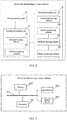
- FIG. 2 is another method for determining a sensor solution provided by an embodiment of the present application. Based on FIG. 1 , as shown in FIG. 2 : Step 201: establishing the simulated unmanned vehicle and the simulation scene, where the simulation scene is used for the simulated unmanned vehicle to perform simulation driving; and determining the first sensor solution according to the initialization parameter.
- step 201 The method and principle of step 201 are similar or the same as those of step 101 and step 102, please refer to the record of step 101 and step 102, which will not be repeated in this embodiment.
- Step 202 determining, according to the first sensor solution, a first sub-simulation data generated by the simulated unmanned vehicle during the simulation driving in a static simulation scene; determining the first perception parameter of the first sensor solution according to the first sub-simulation data, and correcting the first sensor solution according to the first perception parameter to obtain a second sensor solution.
- the static simulation scene may be a visualization scene composed of environmental information when the unmanned vehicle is driving.
- static simulation scenes include visual scenes composed of element models such as roads, houses, green plants, or roadblocks.
- the simulated sensor is installed in the unmanned vehicle.
- the simulated unmanned vehicle automatically drives in the static simulation scene, the simulated sensor scans the static simulation scene to obtain the first sub-simulation data.
- the first sub-simulation data reflects the static simulation scene perceived by the simulated sensor under the first sensor solution, but the static simulation scene perceived by the simulated sensor is not completely consistent with the real static simulation scene. Therefore, the first sensor solution needs to be corrected according to the first sub-simulation data to obtain the second sensor solution.
- the simulated sensor is installed in the simulated unmanned vehicle, and the simulated unmanned vehicle is used to perform simulated driving in the static simulation scene.
- the first sub-simulation data generated by the unmanned vehicle during the simulation driving is input into a preset sensor perception algorithm to obtain the first perception parameter represented by the first sub-simulation data.
- the first perception parameter is a numerical representation of the perception capability of the first sensor solution, and the first perception parameter includes information such as detection range, detection stability, detection accuracy, and detection speed.
- the first sensor solution is corrected to obtain the second sensor solution. Specifically, when the first perception parameter does not meet the preset sensor perception capability requirements, the number, the model, and the installation position of the sensor are adjusted to obtain the adjusted second sensor solution.
- a lidar is the core component of the unmanned vehicle perception system.
- Lidar solutions usually involve multiple lidars.
- the installation solution of multiple lidars is an important factor in determining the perception capability of lidar, and good lidar perception capability is an important factor to guarantee the safe driving of the unmanned vehicle.
- the first lidar solution is determined according to the initialization parameter of the lidar, where the initialization parameter can be determined based on the experience of those skilled in the art, or based on theoretical knowledge, basic requirements, etc. in the field.
- the sensor data generated by the simulated unmanned vehicle during the driving in the simulation scene is point cloud data, and the method of obtaining point cloud data can be implemented by using an existing method, which will not be repeated here.
- the first sub-simulation point cloud is generated by the simulated unmanned vehicle during the driving in the static simulation scene, and the first sub-simulation point cloud is input into the preset point cloud perception algorithm to obtain the first perception parameter represented by the first sub-simulation point cloud.
- the first perception parameter describes the detection range, detection stability, detection accuracy, detection speed and other information of the lidar.
- the first lidar solution is corrected. Specifically, the number, the model, and the installation location of the lidar are adjusted to obtain the adjusted second lidar solution.
- the camera is also the core component of the unmanned vehicle perception system.
- the sensor is a camera
- the sensor data generated by the simulated unmanned vehicle during the driving in the simulation scene is image data.
- the first sub simulation image is generated by the simulated unmanned vehicle during the driving in the static simulation scene, and the first sub simulation image is input into the preset image perception algorithm to obtain the first perception parameter represented by the first sub simulation image; and according to the first perception parameters and the preset camera perception requirements, the first camera solution is corrected to obtain the second camera perception solution.
- y 1 is used to represent the first perception parameter of the first sensor solution
- y 2 is used to represent the second perception parameter of the second sensor solution.
- the perception parameter represented by the first sub-simulation data is the first perception parameter y 1
- the second perception parameter y 2 is determined according to the preset sensor perception capability requirements.
- a 1 x 1 + b 1 y 1 + c 1 0, x 1 represents the variable corresponding to the simulation scene. For a certain simulation scene, the corresponding variable is known and remains unchanged.
- the single factor control experiment is a conventional experimental method in the field, and this embodiment will not be repeated here.
- the process and principle that the first sensor solution is adjusted according to the first perception parameter to obtain the second sensor solution are the same as the above description, which will not be repeated here.
- Step 203 determining, according to the second sensor solution, second sub-simulation data generated by the unmanned vehicle during the simulation driving in a dynamic simulation scene; and determining a second perception parameter of the second sensor solution according to the second sub-simulation data, correcting the second sensor solution according to the second perception parameter to obtain the third sensor solution, and using the third sensor solution as a sensor solution applied to the unmanned vehicle.
- the simulation scene for simulating the driving of the unmanned vehicle includes a static simulation scene as well as a dynamic simulation scene.
- the dynamic simulation scene includes at least one dynamic sub-simulation scene.
- Dynamic sub-simulation scenes can be various driving dynamic scenes that the unmanned vehicle may experience during the driving. For example, it can be a driving dynamic scene such as following the car in a straight lane, overtaking in a straight lane, being overtaken in a straight lane, going straight at an intersection, or turning at an intersection, etc.
- At least one second sub-simulation data generated by the simulated unmanned vehicle during the simulating driving in at least one dynamic sub-simulation scene is determined, each second sub-simulation data in the at least one second sub-simulation data can represent the perception capability of the second sensor solution in the corresponding dynamic sub-simulation scene.
- At least one second sub-simulation data is input into the preset sensor perception algorithm to obtain the second perception parameter of the second sensor solution.
- the second perception parameter is calculated based on at least one second sub-simulation data, which reflects the comprehensive perception capability of the second sensor solution in multiple dynamic sub-simulation scenes.
- the second perception parameter is a numerical representation of the comprehensive perception capability of the second sensor solution. According to the difference between the second perception parameter and the preset sensor perception capability requirement, the number, the model and the installation position of the sensor in the second sensor solution are adjusted.
- the second sensor solution is the determined sensor solution of the simulated unmanned vehicle in the static simulation scene. According to the second sub-simulation data generated by the simulation unmanned vehicle during the driving in the dynamic simulation scene, the second sensor solution is continuously optimized and adjusted to obtain the third sensor solution suitable for the dynamic simulation scene.
- the second sub-simulation data reflects the dynamic simulation scene perceived by the simulated sensor under the second sensor solution.
- the second sub-simulation data is used to correct the second sensor solution, improve the perception capability of the second sensor solution, and obtain the third sensor solution, which can make the dynamic simulation scene perceived by the simulated sensor under the third sensor solution consistent with the real dynamic simulation scene as much as possible.
- the method and principle of correcting the second sensor solution to obtain the third sensor solution are similar or the same as those of correcting the first sensor solution to obtain the second sensor perception solution in step 202. Referring to the relevant records in step 202, and this embodiment will not be repeated here.
- the third sensor solution is a sensor solution that can be applied to the actual unmanned vehicle.
- the model, the number, and the installation location of the simulated sensor installed on the simulated unmanned vehicle are the model, the number, and the installation location of the sensor installed in the actual unmanned vehicle.
- the simulation data is obtained by using the simulated unmanned vehicle during the driving in the simulation scene, the simulation data is used to continuously correct the sensor solution, and finally a sensor solution suitable for the actual unmanned vehicle is obtained.
- the actual driving environment of the unmanned vehicle, the physical parameters of the sensor, the size and appearance of the unmanned vehicle, the morphology of the obstacles and the movement characteristics are fully considered.
- the perception accuracy and perception capability of the sensor solution are guaranteed, which is beneficial to guarantee the safe operation of the unmanned vehicle.
- the embodiment establishes a simulation unmanned vehicle and a simulation scene, where the simulation scene is used for the simulated unmanned vehicle to perform simulation driving; determines the first sensor solution according to the initialization parameter;, determines, according to the first sensor solution, the first sub-simulation data generated by the unmanned vehicle during the simulation driving in the static simulation scene; determines, according to the first sub-simulation data, the first perception parameter of the first sensor solution and corrects the first sensor solution according to the first perception parameter to obtain the second sensor solution; determines, according to the second sensor solution, the second sub-simulation point cloud generated by the unmanned vehicle during the simulation driving in the dynamic simulation scene; and determines, according to the second sub-simulation point cloud, the second perception parameter of the second sensor solution, corrects the second sensor solution according to the second perception parameter to obtain the third sensor solution, and uses the third sensor solution as a sensor solution applied to the unmanned vehicle.
- the first sub-simulation data collected by the simulated sensor in the static simulation scene is used to correct the first sensor solution
- the second sub-simulation data collected by the simulated sensor in the dynamic simulation scene is used to correct the second sensor solution, which fully consider the various static scenes and dynamic scenes that the unmanned vehicle may experience in the actual driving process
- the determined sensor solution applied to the unmanned vehicle is more suitable for the actual driving process requirements of the unmanned vehicle
- the perception capability and the perception accuracy of the sensor solution are more suitable for the various scenes that the unmanned vehicle may experience in the actual driving process. Therefore, the sensor solution applied to the unmanned vehicle determined by this method is more beneficial to guarantee the safe operation of the unmanned vehicle.
- the determined sensor solution Since the perception parameters of the sensor solution are influenced by the physical parameters of the sensor, the size of the obstacle, the size of the unmanned vehicle and other factors, by correcting the sensor solution according to the perception parameter, the determined sensor solution has high perception accuracy and strong perception capability, which is beneficial to guarantee the safe operation of the unmanned vehicle.
- FIG. 3 is a schematic structural diagram of a device for determining a sensor solution provided by an embodiment of the present application. As shown in FIG. 3 , the device includes:
- a simulated unmanned vehicle and a simulation scene are established, where the simulation scene is used for the simulated unmanned vehicle to perform simulation driving; the first sensor solution is determined according to the initialization parameter, and according to the first sensor solution, the simulation data generated by the simulated unmanned vehicle during the simulation driving in the simulation scene is determined; and according to the simulation data, the first perception parameter of the first sensor solution is determined, and according to the first perception parameter, the first sensor solution is corrected to obtain the sensor solution applied to the unmanned vehicle.
- This embodiment determines the first sensor solution according to the initialization parameter by establishing the simulation unmanned vehicle, the simulation scene and the simulated sensor, and corrects the first sensor solution according to the first perception parameter by acquiring the simulation data obtained by the simulated unmanned vehicle during the driving and determining the first perception parameter represented by the simulation data to obtain the sensor solution applied to the unmanned vehicle. Since the first perception parameter is determined by the first sensor solution, the physical parameters of the sensor, the obstacle size and the model size of the unmanned vehicle, the first sensor solution is corrected according to the first perception parameter. The correction process of the sensor solution fully considers the influence of the physical parameters of the sensor, the size of the obstacle and the model size of the unmanned vehicle. Therefore, the determined sensor solution applied to the unmanned vehicle has strong perception capability and high perception accuracy, which can better guarantee the safe operation of the unmanned vehicle.
- FIG. 4 is a schematic structural diagram of another device for determining a sensor solution provided by an embodiment of the present application.
- the simulation scene includes a static simulation scene
- the second processing unit 2 includes:
- the simulation scene includes a static simulation scene and a dynamic simulation scene.
- the dynamic simulation scene includes at least one dynamic sub-simulation scene; and the second processing unit 2 includes:
- the second processing unit 2 includes:
- the third processing unit 3 includes:
- the Sensor includes a lidar and a camera.
- the sensor solution includes one or more of the following: sensor model, number of sensors, and sensor installation location.
- the embodiment establishes a simulation unmanned vehicle and a simulation scene, where the simulation scene is used for the simulated unmanned vehicle to perform simulation driving; determines the first sensor solution according to the initialization parameter;, determines, according to the first sensor solution, the first sub-simulation data generated by the unmanned vehicle during the simulation driving in the static simulation scene; determines, according to the first sub-simulation data, the first perception parameter of the first sensor solution and corrects the first sensor solution according to the first perception parameter to obtain the second sensor solution; determines, according to the second sensor solution, the second sub-simulation point cloud generated by the unmanned vehicle during the simulation driving in the dynamic simulation scene; and determines, according to the second sub-simulation point cloud, the second perception parameter of the second sensor solution, corrects the second sensor solution according to the second perception parameter to obtain the third sensor solution, and uses the third sensor solution as a sensor solution applied to the unmanned vehicle.
- the first sub-simulation data collected by the simulated sensor in the static simulation scene is used to correct the first sensor solution
- the second sub-simulation data collected by the simulated sensor in the dynamic simulation scene is used to correct the second sensor solution, which fully consider the various static scenes and dynamic scenes that the unmanned vehicle may experience in the actual driving process
- the determined sensor solution applied to the unmanned vehicle is more suitable for the actual driving process requirements of the unmanned vehicle
- the perception capability and the perception accuracy of the sensor solution are more suitable for the various scenes that the unmanned vehicle may experience in the actual driving process. Therefore, the sensor solution applied to the unmanned vehicle determined by this method is more beneficial to guarantee the safe operation of the unmanned vehicle.
- the determined sensor solution Since the perception parameters of the sensor solution are influenced by the physical parameters of the sensor, the size of the obstacle, the size of the unmanned vehicle and other factors, by correcting the sensor solution according to the perception parameter, the determined sensor solution has high perception accuracy and strong perception capability, which is beneficial to guarantee the safe operation of the unmanned vehicle.
- the present application also provides electronic equipment and a readable storage medium.
- FIG. 5 it is a block diagram of electronic equipment according to the method for determining a sensor solution in the embodiment of the present application.
- Electronic equipment is intended to represent various forms of digital computers, such as a laptop computer, a desktop computer, a workstation, a personal digital assistant, a server, a blade server, a mainframe computer, and other suitable computers.
- Electronic equipment can also represent various forms of mobile devices, such as personal digital processing, a cellular phone, a smart phone, wearable equipment, and other similar computing devices.
- the components shown herein, their connections and relationships, and their functions are merely examples, and are not intended to limit the implementation of the present application described and/or required herein.
- the electronic equipment includes: one or more processors 501, a memory 502, and interfaces for connecting various components which includes a high-speed interface and a low-speed interface.
- the various components are connected to each other by using different buses, and can be installed on a common motherboard or installed in other ways as required.
- the processor may process instructions executed in the electronic equipment, which includes instructions stored in or on the memory to display graphical information of the graphical user interface (GUI) on an external input/output device (such as display equipment coupled to the interface).
- GUI graphical user interface
- multiple processors and/or multiple buses may be used with multiple memories if necessary.
- multiple electronic equipment can be connected, and each equipment provides some necessary operations (for example, as a server array, a group of blade servers, or a multi-processor system).
- a processor 501 is taken as an example.
- the memory 502 is the non-transitory computer-readable storage medium provided by the present application. Where the memory stores instructions that can be executed by at least one processor, so that the at least one processor executes the method for determining the sensor solution provided in the present application.
- the non-transitory computer-readable storage medium of the present application stores computer instructions, and the computer instructions are used to make the computer execute the method for determining the sensor solution provided in the present application.
- the memory 502 can be used to store non-transitory software programs, non-transitory computer- executable programs, and modules, such as the program instructions/modules corresponding to the method for determining the sensor solution in the embodiment of the present application (for example, the acquisition unit 1, the first processing unit 2, and the second processing unit 3 shown in FIG. 3 ).
- the processor 501 executes various functional applications and data processing of the server by running non instantaneous software programs, instructions and modules stored in the memory 502, that is, implements the method for determining the sensor solution in the foregoing method embodiment.
- the memory 502 may include a storage program area and a storage data area, where the storage program area can store an operating system and an application program required by at least one function; and the storage data area can store data created by the use of electronic equipment determined according to the sensor solution, etc.
- the memory 502 may include a high-speed random access memory, and may also include a non-transitory memory, such as at least one magnetic disk storage component, a flash memory component, or other non-transitory solid-state storage components.
- the memory 502 may optionally include a memory set remotely relative to the processor 501, which may be connected, through the network, to the electronic equipment determined by the sensor solution. Examples of the aforementioned networks include, but are not limited to, the Internet, corporate intranets, local area networks, mobile communication networks, and combinations thereof.
- the electronic equipment of the method for determining the sensor solution may also include: an input device 503 and an output device 504.
- the processor 501, the memory 502, the input device 503, and the output device 504 may be connected by a bus or other methods. In FIG. 5 , the connection by a bus is taken as an example.
- the input device 503 can receive input numeric or character information, and generate key signal input related to the user settings and function control of the electronic equipment determined by the sensor solution, such as a touch screen, a keypad, a mouse, a trackpad, a touchpad, a pointer, one or more mouse buttons, a trackball, a joystick and other input devices.
- the output device 504 may include a display equipment, an auxiliary lighting device (for example, LED), a tactile feedback device (for example, a vibration motor), and the like.
- the display equipment may include, but is not limited to, a liquid crystal display (LCD), a light emitting diode (LED) display, and a plasma display. In some embodiments, the display plasma may be a touch screen.
- Various implementations of the systems and technologies described herein can be implemented in a digital electronic circuit system, an integrated circuit system, an application specific ASIC (application specific integrated circuit), computer hardware, firmware, software, and/or combinations thereof.
- These various embodiments may include: being implemented in one or more computer programs, the one or more computer programs may be executed and/or interpreted on a programmable system including at least one programmable processor,
- the programmable processor may be a dedicated or general programmable processor, which can receive data and instructions from a storage system, at least one input device, and at least one output device, and transmit data and instructions to the storage system, the at least one input device, and the at least one output device.
- the program product includes: a computer program, the computer program is stored in a readable storage medium, at least one processor of the electronic device can read the computer program from a readable storage medium, and at least one processor executes the computer program to make the electronic device execute the solution provided by any one of the foregoing embodiments.
- the system and technology described here can be implemented on a computer.
- the computer has a display device for displaying information to the user (for example, CRT (Cathode Ray Tube) or LCD (Liquid Crystal Display) monitor); and a keyboard and a pointing device (for example, a mouse or a trackball), where the user can provide input to the computer through the keyboard and the pointing device.
- a display device for example, CRT (Cathode Ray Tube) or LCD (Liquid Crystal Display) monitor
- a keyboard and a pointing device for example, a mouse or a trackball
- Other types of devices can also be used to provide interaction with the user.
- the feedback provided to the user can be any form of sensory feedback (for example, visual feedback, auditory feedback, or tactile feedback); and the input from the user can be received by any form (including acoustic input, voice input, or tactile input).
- the systems and technologies described here can be implemented in a computing system that includes back-end components (for example, as a data server), or a computing system that includes middleware components (for example, an application server), or a computing system that includes front-end components (for example, a user computer with a graphical user interface or a web browser through which the user can interact with the implementation of the system and technology described here), or a computing system that includes any combination of such back-end components, middleware components, and front-end components.
- the components of the system can be connected to each other through any form or medium of digital data communication (for example, a communication network). Examples of communication networks include: local area network (LAN), wide area network (WAN), and the Internet.
- Computer systems can include a client and a server.
- the client and server are generally far away from each other and usually interact through a communication network.
- the client and server are generally far away from each other and usually interact through a communication network.
- the relationship between the client and the server is generated by running computer programs that have a client-server relationship with each other on the corresponding computer.
- the above embodiments can refer to and learn from each other, and the same or similar steps and terms will not be repeated one by one. It should be understood that steps can be reordered, added, or deleted by using the various forms of processes shown above. For example, the steps described in the present application can be performed in parallel, sequentially, or a different order, as long as the desired result of the technical solution disclosed in the present application can be achieved, which is not limited herein.
Landscapes
- Engineering & Computer Science (AREA)
- Physics & Mathematics (AREA)
- General Physics & Mathematics (AREA)
- Radar, Positioning & Navigation (AREA)
- Remote Sensing (AREA)
- Electromagnetism (AREA)
- Computer Networks & Wireless Communication (AREA)
- Automation & Control Theory (AREA)
- Geometry (AREA)
- Aviation & Aerospace Engineering (AREA)
- Mechanical Engineering (AREA)
- Transportation (AREA)
- Theoretical Computer Science (AREA)
- Mathematical Physics (AREA)
- Evolutionary Computation (AREA)
- General Engineering & Computer Science (AREA)
- Computational Mathematics (AREA)
- Pure & Applied Mathematics (AREA)
- Chemical & Material Sciences (AREA)
- Analytical Chemistry (AREA)
- Mathematical Optimization (AREA)
- Mathematical Analysis (AREA)
- Computer Vision & Pattern Recognition (AREA)
- Optics & Photonics (AREA)
- Computer Hardware Design (AREA)
- Multimedia (AREA)
- Human Computer Interaction (AREA)
- Traffic Control Systems (AREA)
- Control Of Driving Devices And Active Controlling Of Vehicle (AREA)
- Control Of Position, Course, Altitude, Or Attitude Of Moving Bodies (AREA)
- Business, Economics & Management (AREA)
- Medical Informatics (AREA)
- Game Theory and Decision Science (AREA)
- Artificial Intelligence (AREA)
- Health & Medical Sciences (AREA)
Applications Claiming Priority (1)
| Application Number | Priority Date | Filing Date | Title |
|---|---|---|---|
| CN202010066495.3A CN111324945B (zh) | 2020-01-20 | 2020-01-20 | 传感器方案确定方法、装置、设备及存储介质 |
Publications (3)
| Publication Number | Publication Date |
|---|---|
| EP3816663A2 true EP3816663A2 (de) | 2021-05-05 |
| EP3816663A3 EP3816663A3 (de) | 2021-07-14 |
| EP3816663B1 EP3816663B1 (de) | 2024-08-07 |
Family
ID=71173127
Family Applications (1)
| Application Number | Title | Priority Date | Filing Date |
|---|---|---|---|
| EP21152299.0A Active EP3816663B1 (de) | 2020-01-20 | 2021-01-19 | Verfahren, vorrichtung, ausrüstung und speichermedium zur bestimmung einer sensorlösung |
Country Status (5)
| Country | Link |
|---|---|
| US (1) | US11953605B2 (de) |
| EP (1) | EP3816663B1 (de) |
| JP (1) | JP7274515B2 (de) |
| KR (1) | KR20210038444A (de) |
| CN (1) | CN111324945B (de) |
Cited By (1)
| Publication number | Priority date | Publication date | Assignee | Title |
|---|---|---|---|---|
| AT527251A1 (de) * | 2023-05-22 | 2024-12-15 | Avl List Gmbh | Computerimplementiertes Verfahren zur automatischen Bestimmung einer Anordnung einer Sensoreinrichtung an einem Fahrzeug |
Families Citing this family (11)
| Publication number | Priority date | Publication date | Assignee | Title |
|---|---|---|---|---|
| CN114578322B (zh) * | 2020-11-30 | 2025-08-08 | 阿里巴巴集团控股有限公司 | 激光遮挡率确定方法、设备及存储介质 |
| CN113111513B (zh) * | 2021-04-13 | 2024-04-12 | 上海商汤临港智能科技有限公司 | 传感器配置方案确定方法、装置、计算机设备及存储介质 |
| WO2023010540A1 (zh) * | 2021-08-06 | 2023-02-09 | 深圳市大疆创新科技有限公司 | 激光雷达的扫描结果的验证方法、装置、设备及存储介质 |
| CN113806862B (zh) * | 2021-09-07 | 2022-08-30 | 北京三快在线科技有限公司 | 无人车仿真方法、装置、存储介质及电子设备 |
| US20230145082A1 (en) * | 2021-11-08 | 2023-05-11 | Kinetic Automation Inc. | System and method for automated extrinsic calibration of lidars, cameras, radars and ultrasonic sensors on vehicles and robots |
| CN114419882B (zh) * | 2021-12-30 | 2023-05-02 | 联通智网科技股份有限公司 | 感知系统布置参数优化方法、设备终端及存储介质 |
| CN115278220B (zh) * | 2022-07-29 | 2024-04-30 | 重庆长安汽车股份有限公司 | 车载摄像头仿真测试方法、系统、电子设备及存储介质 |
| CN115452408A (zh) * | 2022-08-26 | 2022-12-09 | 交控科技股份有限公司 | 车载感知设备的测试方法及装置 |
| EP4345491A1 (de) * | 2022-09-30 | 2024-04-03 | Aptiv Technologies Limited | Radarsensor für ein fahrzeug und verfahren zum integrieren eines radarsensors in ein fahrzeug |
| CN115616937B (zh) * | 2022-12-02 | 2023-04-04 | 广汽埃安新能源汽车股份有限公司 | 自动驾驶仿真测试方法、装置、设备和计算机可读介质 |
| CN117434855B (zh) * | 2023-11-09 | 2025-08-26 | 苏州同元软控信息技术有限公司 | 一种自动驾驶仿真方法和系统 |
Family Cites Families (29)
| Publication number | Priority date | Publication date | Assignee | Title |
|---|---|---|---|---|
| DE102004058703B4 (de) * | 2004-09-27 | 2006-11-16 | Daimlerchrysler Ag | Anordnung und Verfahren zum Bestimmen einer Anordnung von Sensoren an einem Kraftfahrzeug |
| PT1788461E (pt) * | 2005-11-22 | 2009-09-24 | Faculte Polytechnique De Mons | Dispositivo e método para conceber uma configuração de sensores para um sistema de segurança automatizado sistema automatizado, elemento de programa e um meio legível por computador |
| JP4861355B2 (ja) * | 2008-02-13 | 2012-01-25 | 株式会社東芝 | 道路交通情報システム |
| WO2014203389A1 (ja) * | 2013-06-21 | 2014-12-24 | 株式会社日立製作所 | センサ配置決定装置およびセンサ配置決定方法 |
| US9671214B2 (en) * | 2013-07-17 | 2017-06-06 | Infineon Technologies Ag | Discrete magnetic angle sensor device, a magnetic angle sensor arrangement, a method for generating an angle signal and a method for providing a sensor signal |
| CN103455663B (zh) * | 2013-08-01 | 2016-09-07 | 上海汽车集团股份有限公司 | 新能源客车切氢切电安全系统的传感器布置方法 |
| JP5829306B2 (ja) * | 2014-05-12 | 2015-12-09 | ファナック株式会社 | レンジセンサの配置位置評価装置 |
| US20160314224A1 (en) * | 2015-04-24 | 2016-10-27 | Northrop Grumman Systems Corporation | Autonomous vehicle simulation system |
| DE102015109169A1 (de) * | 2015-06-10 | 2016-12-15 | Valeo Schalter Und Sensoren Gmbh | Verfahren zum Bestimmen einer Verbauposition einer Sensoreinheit, Kommunikationssystem und Kraftfahrzeug |
| JP7036732B2 (ja) * | 2015-11-04 | 2022-03-15 | ズークス インコーポレイテッド | 自律車両のためのシミュレーションシステムおよび方法 |
| US10496766B2 (en) | 2015-11-05 | 2019-12-03 | Zoox, Inc. | Simulation system and methods for autonomous vehicles |
| EP3371023B1 (de) | 2015-11-04 | 2025-06-04 | Zoox, Inc. | Simulationssystem und -verfahren für autonome fahrzeuge |
| US10489529B2 (en) | 2016-10-14 | 2019-11-26 | Zoox, Inc. | Scenario description language |
| WO2018125928A1 (en) * | 2016-12-29 | 2018-07-05 | DeepScale, Inc. | Multi-channel sensor simulation for autonomous control systems |
| US10401866B2 (en) | 2017-05-03 | 2019-09-03 | GM Global Technology Operations LLC | Methods and systems for lidar point cloud anomalies |
| CN109032102B (zh) * | 2017-06-09 | 2020-12-18 | 百度在线网络技术(北京)有限公司 | 无人驾驶车辆测试方法、装置、设备及存储介质 |
| CN110799804A (zh) * | 2017-06-30 | 2020-02-14 | 深圳市大疆创新科技有限公司 | 地图生成系统和方法 |
| CN107436986A (zh) * | 2017-08-07 | 2017-12-05 | 北京汽车研究总院有限公司 | 车辆主动安全系统的集成装置及仿真应用方法 |
| CN107844858B (zh) * | 2017-10-25 | 2021-11-02 | 驭势科技(北京)有限公司 | 一种用于智能驾驶场景确定定位特征及布局的方法与系统 |
| US20190179979A1 (en) * | 2017-12-13 | 2019-06-13 | Uber Technologies, Inc. | Simulated Sensor Testing |
| WO2019169604A1 (en) * | 2018-03-08 | 2019-09-12 | Baidu.Com Times Technology (Beijing) Co., Ltd. | Simulation-based method to evaluate perception requirement for autonomous driving vehicles |
| GB2573738A (en) * | 2018-03-27 | 2019-11-20 | Points Protector Ltd | Driving monitoring |
| CN109515448B (zh) * | 2018-12-12 | 2021-06-01 | 安徽江淮汽车集团股份有限公司 | 一种自动驾驶传感器布置方法和结构 |
| CN109444350B (zh) * | 2018-12-27 | 2021-09-24 | 中山大学 | 一种基于无人机的大气污染物监测传感器的布局方法 |
| CN109709824A (zh) * | 2018-12-29 | 2019-05-03 | 百度在线网络技术(北京)有限公司 | 在环仿真方法、平台及系统、服务器、计算机可读介质 |
| EP3921811A4 (de) * | 2019-02-06 | 2023-03-15 | Foretellix Ltd. | Simulation und validierung eines autonomen fahrzeugsystems und von komponenten |
| CN109960857B (zh) | 2019-02-28 | 2023-05-23 | 东软睿驰汽车技术(沈阳)有限公司 | 一种激光雷达的仿真方法、装置及仿真平台 |
| CN110162089B (zh) * | 2019-05-30 | 2020-11-03 | 北京三快在线科技有限公司 | 一种无人驾驶的仿真方法及装置 |
| CN110412374B (zh) * | 2019-07-24 | 2024-02-23 | 苏州瑞地测控技术有限公司 | 一种基于多传感器的adas hil测试系统 |
-
2020
- 2020-01-20 CN CN202010066495.3A patent/CN111324945B/zh active Active
-
2021
- 2021-01-18 US US17/151,482 patent/US11953605B2/en active Active
- 2021-01-19 KR KR1020210007319A patent/KR20210038444A/ko not_active Ceased
- 2021-01-19 EP EP21152299.0A patent/EP3816663B1/de active Active
- 2021-01-19 JP JP2021006472A patent/JP7274515B2/ja active Active
Cited By (1)
| Publication number | Priority date | Publication date | Assignee | Title |
|---|---|---|---|---|
| AT527251A1 (de) * | 2023-05-22 | 2024-12-15 | Avl List Gmbh | Computerimplementiertes Verfahren zur automatischen Bestimmung einer Anordnung einer Sensoreinrichtung an einem Fahrzeug |
Also Published As
| Publication number | Publication date |
|---|---|
| JP2021098506A (ja) | 2021-07-01 |
| US11953605B2 (en) | 2024-04-09 |
| JP7274515B2 (ja) | 2023-05-16 |
| KR20210038444A (ko) | 2021-04-07 |
| CN111324945A (zh) | 2020-06-23 |
| CN111324945B (zh) | 2023-09-26 |
| EP3816663A3 (de) | 2021-07-14 |
| US20210190961A1 (en) | 2021-06-24 |
| EP3816663B1 (de) | 2024-08-07 |
Similar Documents
| Publication | Publication Date | Title |
|---|---|---|
| US11953605B2 (en) | Method, device, equipment, and storage medium for determining sensor solution | |
| US11698262B2 (en) | Method and apparatus for generating route planning model, and storage medium | |
| US11586218B2 (en) | Method and apparatus for positioning vehicle, electronic device and storage medium | |
| JP2021119507A (ja) | 車線の決定方法、車線測位精度の評価方法、車線の決定装置、車線測位精度の評価装置、電子デバイス、コンピュータ可読記憶媒体、及びプログラム | |
| EP3893148A1 (de) | Verfahren und vorrichtung zur steuerung eines fahrzeugs und fahrzeug | |
| EP3869399A2 (de) | Fahrzeuginformationdetektionsverfahren und -einrichtung, elektronische vorrichtung, speichermedium und programm | |
| EP3862723A2 (de) | Verfahren und vorrichtung zur erfassung der kartenqualität | |
| CN110793544B (zh) | 路侧感知传感器参数标定方法、装置、设备及存储介质 | |
| CN110723079B (zh) | 车载传感器的位姿调整方法、装置、设备和介质 | |
| JP2021152906A (ja) | 車両軌跡の予測方法、装置、機器及び記憶媒体 | |
| CN111177869B (zh) | 传感器布局方案的确定方法、装置及设备 | |
| KR102694715B1 (ko) | 장애물의 검출 방법, 전자 기기, 노변 기기 및 클라우드 컨트롤 플랫폼 | |
| CN110794844B (zh) | 自动驾驶方法、装置、电子设备及可读存储介质 | |
| CN112184914B (zh) | 目标对象三维位置的确定方法、装置和路侧设备 | |
| CN111368760B (zh) | 一种障碍物检测方法、装置、电子设备及存储介质 | |
| CN111324115A (zh) | 障碍物位置检测融合方法、装置、电子设备和存储介质 | |
| CN113844463B (zh) | 基于自动驾驶系统的车辆控制方法、装置及车辆 | |
| CN112147632A (zh) | 车载激光雷达感知算法的测试方法、装置、设备和介质 | |
| JP2021173745A (ja) | 車両が位置する車線を決定する方法、装置、機器、および記憶媒体 | |
| CN111079079B (zh) | 数据修正方法、装置、电子设备及计算机可读存储介质 | |
| JP2021099877A (ja) | 専用車道での走行をリマインダーする方法、装置、機器及び記憶媒体 | |
| CN111310840B (zh) | 数据融合处理方法、装置、设备和存储介质 | |
| EP4198901A1 (de) | Verfahren und vorrichtung zur kalibrierung extrinsischer kameraparameter | |
| US11697428B2 (en) | Method and apparatus for 3D modeling | |
| CN113887400A (zh) | 障碍物检测方法、模型训练方法、装置及自动驾驶车辆 |
Legal Events
| Date | Code | Title | Description |
|---|---|---|---|
| PUAI | Public reference made under article 153(3) epc to a published international application that has entered the european phase |
Free format text: ORIGINAL CODE: 0009012 |
|
| STAA | Information on the status of an ep patent application or granted ep patent |
Free format text: STATUS: REQUEST FOR EXAMINATION WAS MADE |
|
| 17P | Request for examination filed |
Effective date: 20210119 |
|
| AK | Designated contracting states |
Kind code of ref document: A2 Designated state(s): AL AT BE BG CH CY CZ DE DK EE ES FI FR GB GR HR HU IE IS IT LI LT LU LV MC MK MT NL NO PL PT RO RS SE SI SK SM TR |
|
| PUAL | Search report despatched |
Free format text: ORIGINAL CODE: 0009013 |
|
| AK | Designated contracting states |
Kind code of ref document: A3 Designated state(s): AL AT BE BG CH CY CZ DE DK EE ES FI FR GB GR HR HU IE IS IT LI LT LU LV MC MK MT NL NO PL PT RO RS SE SI SK SM TR |
|
| RIC1 | Information provided on ipc code assigned before grant |
Ipc: G01S 7/497 20060101AFI20210608BHEP Ipc: G01S 7/52 20060101ALI20210608BHEP Ipc: G01S 17/931 20200101ALI20210608BHEP Ipc: G01S 17/89 20200101ALI20210608BHEP Ipc: G01S 17/86 20200101ALI20210608BHEP Ipc: G01S 17/87 20200101ALI20210608BHEP |
|
| STAA | Information on the status of an ep patent application or granted ep patent |
Free format text: STATUS: EXAMINATION IS IN PROGRESS |
|
| 17Q | First examination report despatched |
Effective date: 20221104 |
|
| GRAP | Despatch of communication of intention to grant a patent |
Free format text: ORIGINAL CODE: EPIDOSNIGR1 |
|
| STAA | Information on the status of an ep patent application or granted ep patent |
Free format text: STATUS: GRANT OF PATENT IS INTENDED |
|
| INTG | Intention to grant announced |
Effective date: 20240301 |
|
| GRAS | Grant fee paid |
Free format text: ORIGINAL CODE: EPIDOSNIGR3 |
|
| GRAA | (expected) grant |
Free format text: ORIGINAL CODE: 0009210 |
|
| STAA | Information on the status of an ep patent application or granted ep patent |
Free format text: STATUS: THE PATENT HAS BEEN GRANTED |
|
| P01 | Opt-out of the competence of the unified patent court (upc) registered |
Free format text: CASE NUMBER: APP_33329/2024 Effective date: 20240604 |
|
| AK | Designated contracting states |
Kind code of ref document: B1 Designated state(s): AL AT BE BG CH CY CZ DE DK EE ES FI FR GB GR HR HU IE IS IT LI LT LU LV MC MK MT NL NO PL PT RO RS SE SI SK SM TR |
|
| REG | Reference to a national code |
Ref country code: GB Ref legal event code: FG4D |
|
| REG | Reference to a national code |
Ref country code: CH Ref legal event code: EP |
|
| REG | Reference to a national code |
Ref country code: IE Ref legal event code: FG4D |
|
| REG | Reference to a national code |
Ref country code: DE Ref legal event code: R096 Ref document number: 602021016634 Country of ref document: DE |
|
| REG | Reference to a national code |
Ref country code: LT Ref legal event code: MG9D |
|
| REG | Reference to a national code |
Ref country code: NL Ref legal event code: MP Effective date: 20240807 |
|
| PG25 | Lapsed in a contracting state [announced via postgrant information from national office to epo] |
Ref country code: NO Free format text: LAPSE BECAUSE OF FAILURE TO SUBMIT A TRANSLATION OF THE DESCRIPTION OR TO PAY THE FEE WITHIN THE PRESCRIBED TIME-LIMIT Effective date: 20241107 |
|
| REG | Reference to a national code |
Ref country code: AT Ref legal event code: MK05 Ref document number: 1711544 Country of ref document: AT Kind code of ref document: T Effective date: 20240807 |
|
| PG25 | Lapsed in a contracting state [announced via postgrant information from national office to epo] |
Ref country code: NL Free format text: LAPSE BECAUSE OF FAILURE TO SUBMIT A TRANSLATION OF THE DESCRIPTION OR TO PAY THE FEE WITHIN THE PRESCRIBED TIME-LIMIT Effective date: 20240807 Ref country code: FI Free format text: LAPSE BECAUSE OF FAILURE TO SUBMIT A TRANSLATION OF THE DESCRIPTION OR TO PAY THE FEE WITHIN THE PRESCRIBED TIME-LIMIT Effective date: 20240807 Ref country code: PT Free format text: LAPSE BECAUSE OF FAILURE TO SUBMIT A TRANSLATION OF THE DESCRIPTION OR TO PAY THE FEE WITHIN THE PRESCRIBED TIME-LIMIT Effective date: 20241209 Ref country code: PL Free format text: LAPSE BECAUSE OF FAILURE TO SUBMIT A TRANSLATION OF THE DESCRIPTION OR TO PAY THE FEE WITHIN THE PRESCRIBED TIME-LIMIT Effective date: 20240807 Ref country code: GR Free format text: LAPSE BECAUSE OF FAILURE TO SUBMIT A TRANSLATION OF THE DESCRIPTION OR TO PAY THE FEE WITHIN THE PRESCRIBED TIME-LIMIT Effective date: 20241108 |
|
| PG25 | Lapsed in a contracting state [announced via postgrant information from national office to epo] |
Ref country code: BG Free format text: LAPSE BECAUSE OF FAILURE TO SUBMIT A TRANSLATION OF THE DESCRIPTION OR TO PAY THE FEE WITHIN THE PRESCRIBED TIME-LIMIT Effective date: 20240807 |
|
| PG25 | Lapsed in a contracting state [announced via postgrant information from national office to epo] |
Ref country code: LV Free format text: LAPSE BECAUSE OF FAILURE TO SUBMIT A TRANSLATION OF THE DESCRIPTION OR TO PAY THE FEE WITHIN THE PRESCRIBED TIME-LIMIT Effective date: 20240807 |
|
| PG25 | Lapsed in a contracting state [announced via postgrant information from national office to epo] |
Ref country code: AT Free format text: LAPSE BECAUSE OF FAILURE TO SUBMIT A TRANSLATION OF THE DESCRIPTION OR TO PAY THE FEE WITHIN THE PRESCRIBED TIME-LIMIT Effective date: 20240807 Ref country code: IS Free format text: LAPSE BECAUSE OF FAILURE TO SUBMIT A TRANSLATION OF THE DESCRIPTION OR TO PAY THE FEE WITHIN THE PRESCRIBED TIME-LIMIT Effective date: 20241207 |
|
| PG25 | Lapsed in a contracting state [announced via postgrant information from national office to epo] |
Ref country code: HR Free format text: LAPSE BECAUSE OF FAILURE TO SUBMIT A TRANSLATION OF THE DESCRIPTION OR TO PAY THE FEE WITHIN THE PRESCRIBED TIME-LIMIT Effective date: 20240807 |
|
| PG25 | Lapsed in a contracting state [announced via postgrant information from national office to epo] |
Ref country code: ES Free format text: LAPSE BECAUSE OF FAILURE TO SUBMIT A TRANSLATION OF THE DESCRIPTION OR TO PAY THE FEE WITHIN THE PRESCRIBED TIME-LIMIT Effective date: 20240807 Ref country code: RS Free format text: LAPSE BECAUSE OF FAILURE TO SUBMIT A TRANSLATION OF THE DESCRIPTION OR TO PAY THE FEE WITHIN THE PRESCRIBED TIME-LIMIT Effective date: 20241107 |
|
| PG25 | Lapsed in a contracting state [announced via postgrant information from national office to epo] |
Ref country code: RS Free format text: LAPSE BECAUSE OF FAILURE TO SUBMIT A TRANSLATION OF THE DESCRIPTION OR TO PAY THE FEE WITHIN THE PRESCRIBED TIME-LIMIT Effective date: 20241107 Ref country code: PT Free format text: LAPSE BECAUSE OF FAILURE TO SUBMIT A TRANSLATION OF THE DESCRIPTION OR TO PAY THE FEE WITHIN THE PRESCRIBED TIME-LIMIT Effective date: 20241209 Ref country code: PL Free format text: LAPSE BECAUSE OF FAILURE TO SUBMIT A TRANSLATION OF THE DESCRIPTION OR TO PAY THE FEE WITHIN THE PRESCRIBED TIME-LIMIT Effective date: 20240807 Ref country code: NO Free format text: LAPSE BECAUSE OF FAILURE TO SUBMIT A TRANSLATION OF THE DESCRIPTION OR TO PAY THE FEE WITHIN THE PRESCRIBED TIME-LIMIT Effective date: 20241107 Ref country code: NL Free format text: LAPSE BECAUSE OF FAILURE TO SUBMIT A TRANSLATION OF THE DESCRIPTION OR TO PAY THE FEE WITHIN THE PRESCRIBED TIME-LIMIT Effective date: 20240807 Ref country code: LV Free format text: LAPSE BECAUSE OF FAILURE TO SUBMIT A TRANSLATION OF THE DESCRIPTION OR TO PAY THE FEE WITHIN THE PRESCRIBED TIME-LIMIT Effective date: 20240807 Ref country code: IS Free format text: LAPSE BECAUSE OF FAILURE TO SUBMIT A TRANSLATION OF THE DESCRIPTION OR TO PAY THE FEE WITHIN THE PRESCRIBED TIME-LIMIT Effective date: 20241207 Ref country code: HR Free format text: LAPSE BECAUSE OF FAILURE TO SUBMIT A TRANSLATION OF THE DESCRIPTION OR TO PAY THE FEE WITHIN THE PRESCRIBED TIME-LIMIT Effective date: 20240807 Ref country code: GR Free format text: LAPSE BECAUSE OF FAILURE TO SUBMIT A TRANSLATION OF THE DESCRIPTION OR TO PAY THE FEE WITHIN THE PRESCRIBED TIME-LIMIT Effective date: 20241108 Ref country code: FI Free format text: LAPSE BECAUSE OF FAILURE TO SUBMIT A TRANSLATION OF THE DESCRIPTION OR TO PAY THE FEE WITHIN THE PRESCRIBED TIME-LIMIT Effective date: 20240807 Ref country code: ES Free format text: LAPSE BECAUSE OF FAILURE TO SUBMIT A TRANSLATION OF THE DESCRIPTION OR TO PAY THE FEE WITHIN THE PRESCRIBED TIME-LIMIT Effective date: 20240807 Ref country code: BG Free format text: LAPSE BECAUSE OF FAILURE TO SUBMIT A TRANSLATION OF THE DESCRIPTION OR TO PAY THE FEE WITHIN THE PRESCRIBED TIME-LIMIT Effective date: 20240807 Ref country code: AT Free format text: LAPSE BECAUSE OF FAILURE TO SUBMIT A TRANSLATION OF THE DESCRIPTION OR TO PAY THE FEE WITHIN THE PRESCRIBED TIME-LIMIT Effective date: 20240807 |
|
| PG25 | Lapsed in a contracting state [announced via postgrant information from national office to epo] |
Ref country code: DK Free format text: LAPSE BECAUSE OF FAILURE TO SUBMIT A TRANSLATION OF THE DESCRIPTION OR TO PAY THE FEE WITHIN THE PRESCRIBED TIME-LIMIT Effective date: 20240807 Ref country code: SM Free format text: LAPSE BECAUSE OF FAILURE TO SUBMIT A TRANSLATION OF THE DESCRIPTION OR TO PAY THE FEE WITHIN THE PRESCRIBED TIME-LIMIT Effective date: 20240807 |
|
| PG25 | Lapsed in a contracting state [announced via postgrant information from national office to epo] |
Ref country code: EE Free format text: LAPSE BECAUSE OF FAILURE TO SUBMIT A TRANSLATION OF THE DESCRIPTION OR TO PAY THE FEE WITHIN THE PRESCRIBED TIME-LIMIT Effective date: 20240807 |
|
| PG25 | Lapsed in a contracting state [announced via postgrant information from national office to epo] |
Ref country code: CZ Free format text: LAPSE BECAUSE OF FAILURE TO SUBMIT A TRANSLATION OF THE DESCRIPTION OR TO PAY THE FEE WITHIN THE PRESCRIBED TIME-LIMIT Effective date: 20240807 |
|
| PG25 | Lapsed in a contracting state [announced via postgrant information from national office to epo] |
Ref country code: SK Free format text: LAPSE BECAUSE OF FAILURE TO SUBMIT A TRANSLATION OF THE DESCRIPTION OR TO PAY THE FEE WITHIN THE PRESCRIBED TIME-LIMIT Effective date: 20240807 |
|
| REG | Reference to a national code |
Ref country code: DE Ref legal event code: R097 Ref document number: 602021016634 Country of ref document: DE |
|
| PLBE | No opposition filed within time limit |
Free format text: ORIGINAL CODE: 0009261 |
|
| STAA | Information on the status of an ep patent application or granted ep patent |
Free format text: STATUS: NO OPPOSITION FILED WITHIN TIME LIMIT |
|
| 26N | No opposition filed |
Effective date: 20250508 |
|
| REG | Reference to a national code |
Ref country code: CH Ref legal event code: PL |
|
| PG25 | Lapsed in a contracting state [announced via postgrant information from national office to epo] |
Ref country code: SE Free format text: LAPSE BECAUSE OF FAILURE TO SUBMIT A TRANSLATION OF THE DESCRIPTION OR TO PAY THE FEE WITHIN THE PRESCRIBED TIME-LIMIT Effective date: 20240807 |
|
| PG25 | Lapsed in a contracting state [announced via postgrant information from national office to epo] |
Ref country code: LU Free format text: LAPSE BECAUSE OF NON-PAYMENT OF DUE FEES Effective date: 20250119 Ref country code: MC Free format text: LAPSE BECAUSE OF FAILURE TO SUBMIT A TRANSLATION OF THE DESCRIPTION OR TO PAY THE FEE WITHIN THE PRESCRIBED TIME-LIMIT Effective date: 20240807 |
|
| GBPC | Gb: european patent ceased through non-payment of renewal fee |
Effective date: 20250119 |
|
| PG25 | Lapsed in a contracting state [announced via postgrant information from national office to epo] |
Ref country code: GB Free format text: LAPSE BECAUSE OF NON-PAYMENT OF DUE FEES Effective date: 20250119 Ref country code: BE Free format text: LAPSE BECAUSE OF NON-PAYMENT OF DUE FEES Effective date: 20250131 |
|
| PG25 | Lapsed in a contracting state [announced via postgrant information from national office to epo] |
Ref country code: FR Free format text: LAPSE BECAUSE OF NON-PAYMENT OF DUE FEES Effective date: 20250131 |
|
| PG25 | Lapsed in a contracting state [announced via postgrant information from national office to epo] |
Ref country code: CH Free format text: LAPSE BECAUSE OF NON-PAYMENT OF DUE FEES Effective date: 20250131 |
|
| REG | Reference to a national code |
Ref country code: BE Ref legal event code: MM Effective date: 20250131 |
|
| PG25 | Lapsed in a contracting state [announced via postgrant information from national office to epo] |
Ref country code: IE Free format text: LAPSE BECAUSE OF NON-PAYMENT OF DUE FEES Effective date: 20250119 |
|
| PG25 | Lapsed in a contracting state [announced via postgrant information from national office to epo] |
Ref country code: IT Free format text: LAPSE BECAUSE OF FAILURE TO SUBMIT A TRANSLATION OF THE DESCRIPTION OR TO PAY THE FEE WITHIN THE PRESCRIBED TIME-LIMIT Effective date: 20240807 |
|
| PGFP | Annual fee paid to national office [announced via postgrant information from national office to epo] |
Ref country code: DE Payment date: 20260120 Year of fee payment: 6 |
|
| PG25 | Lapsed in a contracting state [announced via postgrant information from national office to epo] |
Ref country code: RO Free format text: LAPSE BECAUSE OF FAILURE TO SUBMIT A TRANSLATION OF THE DESCRIPTION OR TO PAY THE FEE WITHIN THE PRESCRIBED TIME-LIMIT Effective date: 20240807 |