EP3817112A1 - Pile à combustible, véhicule pourvu de dispositif de pile à combustible et dispositif de conditionnement pourvu de dispositif de pile à combustible - Google Patents
Pile à combustible, véhicule pourvu de dispositif de pile à combustible et dispositif de conditionnement pourvu de dispositif de pile à combustible Download PDFInfo
- Publication number
- EP3817112A1 EP3817112A1 EP20204521.7A EP20204521A EP3817112A1 EP 3817112 A1 EP3817112 A1 EP 3817112A1 EP 20204521 A EP20204521 A EP 20204521A EP 3817112 A1 EP3817112 A1 EP 3817112A1
- Authority
- EP
- European Patent Office
- Prior art keywords
- fuel cell
- cell device
- heat
- cell stack
- recess
- Prior art date
- Legal status (The legal status is an assumption and is not a legal conclusion. Google has not performed a legal analysis and makes no representation as to the accuracy of the status listed.)
- Granted
Links
Images

Classifications
-
- H—ELECTRICITY
- H01—ELECTRIC ELEMENTS
- H01M—PROCESSES OR MEANS, e.g. BATTERIES, FOR THE DIRECT CONVERSION OF CHEMICAL ENERGY INTO ELECTRICAL ENERGY
- H01M8/00—Fuel cells; Manufacture thereof
- H01M8/04—Auxiliary arrangements, e.g. for control of pressure or for circulation of fluids
- H01M8/04007—Auxiliary arrangements, e.g. for control of pressure or for circulation of fluids related to heat exchange
- H01M8/04014—Heat exchange using gaseous fluids; Heat exchange by combustion of reactants
-
- H—ELECTRICITY
- H01—ELECTRIC ELEMENTS
- H01M—PROCESSES OR MEANS, e.g. BATTERIES, FOR THE DIRECT CONVERSION OF CHEMICAL ENERGY INTO ELECTRICAL ENERGY
- H01M8/00—Fuel cells; Manufacture thereof
- H01M8/10—Fuel cells with solid electrolytes
- H01M8/1016—Fuel cells with solid electrolytes characterised by the electrolyte material
- H01M8/1018—Polymeric electrolyte materials
-
- H—ELECTRICITY
- H01—ELECTRIC ELEMENTS
- H01M—PROCESSES OR MEANS, e.g. BATTERIES, FOR THE DIRECT CONVERSION OF CHEMICAL ENERGY INTO ELECTRICAL ENERGY
- H01M8/00—Fuel cells; Manufacture thereof
- H01M8/24—Grouping of fuel cells, e.g. stacking of fuel cells
-
- H—ELECTRICITY
- H01—ELECTRIC ELEMENTS
- H01M—PROCESSES OR MEANS, e.g. BATTERIES, FOR THE DIRECT CONVERSION OF CHEMICAL ENERGY INTO ELECTRICAL ENERGY
- H01M2250/00—Fuel cells for particular applications; Specific features of fuel cell system
- H01M2250/20—Fuel cells in motive systems, e.g. vehicle, ship, plane
-
- Y—GENERAL TAGGING OF NEW TECHNOLOGICAL DEVELOPMENTS; GENERAL TAGGING OF CROSS-SECTIONAL TECHNOLOGIES SPANNING OVER SEVERAL SECTIONS OF THE IPC; TECHNICAL SUBJECTS COVERED BY FORMER USPC CROSS-REFERENCE ART COLLECTIONS [XRACs] AND DIGESTS
- Y02—TECHNOLOGIES OR APPLICATIONS FOR MITIGATION OR ADAPTATION AGAINST CLIMATE CHANGE
- Y02E—REDUCTION OF GREENHOUSE GAS [GHG] EMISSIONS, RELATED TO ENERGY GENERATION, TRANSMISSION OR DISTRIBUTION
- Y02E60/00—Enabling technologies; Technologies with a potential or indirect contribution to GHG emissions mitigation
- Y02E60/30—Hydrogen technology
- Y02E60/50—Fuel cells
-
- Y—GENERAL TAGGING OF NEW TECHNOLOGICAL DEVELOPMENTS; GENERAL TAGGING OF CROSS-SECTIONAL TECHNOLOGIES SPANNING OVER SEVERAL SECTIONS OF THE IPC; TECHNICAL SUBJECTS COVERED BY FORMER USPC CROSS-REFERENCE ART COLLECTIONS [XRACs] AND DIGESTS
- Y02—TECHNOLOGIES OR APPLICATIONS FOR MITIGATION OR ADAPTATION AGAINST CLIMATE CHANGE
- Y02T—CLIMATE CHANGE MITIGATION TECHNOLOGIES RELATED TO TRANSPORTATION
- Y02T90/00—Enabling technologies or technologies with a potential or indirect contribution to GHG emissions mitigation
- Y02T90/40—Application of hydrogen technology to transportation, e.g. using fuel cells
Definitions
- the present invention relates to a fuel cell device.
- the present invention also relates to a vehicle, in particular an aircraft, with a fuel cell device.
- the present invention also relates to a conditioning device for a gaseous medium, in particular air, with a fuel cell device.
- Fuel cell devices are known in which electrical energy is generated by the reaction of hydrogen and oxygen, in particular atmospheric oxygen. These include, for example, polymer electrolyte (PEM) fuel cells.
- PEM polymer electrolyte
- the fuel cell is preferably cooled in order to maintain an operating temperature that is as constant as possible.
- PEM fuel cells it is also important to maintain a certain humidity level of the membrane in order to maintain the operating point.
- a heat exchanger is to be provided which is positioned spatially remote from the fuel cell device.
- Fuel cell devices are used, for example, in vehicles, in particular aircraft.
- the two first-mentioned cooling concepts have the disadvantage in this context that air inlets for an adjustable air volume flow must be provided for the heat exchanger or the fuel cell device. This is disadvantageous because the resistance of the aircraft is increased. Nevertheless, these two first-mentioned concepts prove to be more advantageous than the third concept, because in this case the efficiency of the fuel cell device decreases.
- waste heat from the fuel cell device for example for air conditioning applications or for internal processes.
- the latter includes, for example, the evaporation of liquid hydrogen, which is required for operation.
- the object of the present invention is to provide a fuel cell device with improved cooling properties.
- a fuel cell device comprising a plurality of fuel cells which are arranged one above the other in a stacking direction and form a fuel cell stack, one in the fuel cell stack penetrating the fuel cells in the stacking direction Recess is formed and in the recess at least one heat conducting element is arranged in thermal contact with the fuel cells.
- the fuel cell stack has one and in particular at least one recess on the inside.
- the fuel cells are configured in an annular manner.
- a heat conducting element is arranged in the recess. In this way, heat can be transferred from the fuel cells to the heat-conducting element.
- the heat conducting element can be cooled by convection and heat can be dissipated. It has been shown that the arrangement of the at least one heat-conducting element on the inside in the fuel cell stack leads to advantageous cooling properties.
- the recess is advantageously a through opening from a first end side of the fuel cell stack to a second end side of the fuel cell stack.
- the fuel cell stack preferably forms a hollow cylinder, advantageously a vertical hollow cylinder.
- the through-opening has the advantage that a flow of cooling air can flow through the fuel cell stack and heat can be dissipated particularly effectively.
- the fuel cells are each ring-shaped and jointly form a jacket-shaped outer peripheral surface of the fuel cell stack with an outer edge and jointly form an inner peripheral surface of the fuel cell stack enclosing the recess with an inner edge.
- the at least one heat-conducting element extends along the entire or essentially the entire recess. It is particularly advantageous if the heat-conducting element extends from the first end side to the second end side of the fuel cell stack.
- the at least one heat-conducting element is advantageously arranged on an inner circumferential surface of the fuel cell stack which surrounds the recess. As a result of the arrangement on the inner circumferential surface, particularly good thermal contact of the at least one heat-conducting element with the fuel cell stack can be ensured.
- the heat-conducting element is a convectively cooled heat-conducting element.
- the structural design of the fuel cell device can thereby be kept particularly simple. This is surrounded by cooling air, for example. Cooling air can flow into the recess and, for example in the case of a through opening, flow through the fuel cell stack.
- the at least one heat-conducting element is designed, for example, as a heat pipe.
- the heat pipe has an enclosed receiving space for a heat transfer medium, which on the one hand can evaporate and on the other hand can condense.
- the heat transfer medium is essentially completely in the saturated steam area, so that the heat pipe has an essentially constant temperature. Heat can be dissipated particularly efficiently via the heat pipe. A temperature gradient over the length of the heat pipe can preferably be avoided.
- the fuel cell device has at least one heat-conducting element in thermal contact with the fuel cells on an outer lateral surface of the fuel cell stack. In this way, it is possible to dissipate heat from the jacket surface and to cool the fuel cells in a more targeted manner. This favors a temperature distribution in the fuel cell stack that is as uniform as possible.
- the heat conducting element arranged on the outside is advantageously convectively cooled and / or designed as a heat pipe.
- the heat conducting element expediently extends from a first end side to a second end side of the fuel cell stack.
- the at least one heat-conducting element is preferably aligned parallel to the stacking direction in the recess and / or on the jacket surface.
- the at least one heat-conducting element is preferably cuboid and / or elongated.
- heat-conducting elements are present, these are preferably aligned parallel to one another.
- a plurality of heat conducting elements is arranged on an outer lateral surface of the fuel cell stack in order to promote the dissipation of heat on the lateral surface, with regard to the most homogeneous temperature distribution possible in the fuel cells.
- the heat conducting elements are preferably designed identically, in particular those in the recess and / or those on the jacket surface and particularly advantageously all the heat conducting elements as a whole.
- the heat conducting elements are advantageously arranged equidistantly in the circumferential direction of the fuel cell stack on an inner circumferential surface enclosing the recess and / or on the outer lateral surface.
- the uniform arrangement favors the dissipation of heat from the fuel cells via the heat conducting elements.
- heat conducting elements are provided on the inner circumferential surface of the fuel cell stack.
- eight heat-conducting elements can be provided on the outer lateral surface.
- a respective heat-conducting element arranged on the inside is assigned in the radial direction a heat-conducting element lying opposite on the outside on the lateral surface.
- radial is to be understood as referring to an axis defined by the fuel cell stack.
- the recess in the fuel cells runs in the stacking direction and / or a jacket surface of the fuel cell stack comprises at least one groove into which the at least one heat-conducting element engages partially and preferably with a form fit.
- the fuel cells can comprise a respective recess on the inner circumferential surface.
- a groove is created.
- at least one groove can be formed on the outer lateral surface.
- the at least one heat-conducting element engages in the groove and advantageously extends along the entire or substantially the entire extent of the groove. The engagement in the groove promotes the release of heat from the fuel cell stack to the heat-conducting element.
- the section of the heat-conducting element protruding from the groove can preferably be convectively cooled for heat dissipation.
- the at least one heat-conducting element engages approximately halfway into the groove.
- the at least one heat-conducting element is in indirect thermal contact with the fuel cell stack via a thermally conductive contact medium, the contact medium preferably being formed in layers.
- a thermally conductive paste or a thermally conductive elastomer is provided as the contact medium, via which the heat is transferred to the thermally conductive element.
- the contact medium advantageously has a function of frictional connection of the heat-conducting element to the fuel cell stack.
- the fuel cells have an octagonal outer contour in plan view in the stacking direction, in particular not taking into account any recesses for the groove (s).
- the recess has a contour that matches the contour of the fuel cells, in particular not taking into account any recesses for the groove (s). This proves to be advantageous for the heat transport and the cooling of the fuel cell stack, in particular when heat conducting elements are arranged on the inside in the recess and on the outside on the outer surface of the fuel cell stack.
- the contour of the recess is advantageously congruent with the contour of the fuel cells, in particular not taking into account any recesses for the groove (s).
- the fuel cells are PEM fuel cells.
- the present invention also relates to a vehicle.
- the object of the present invention is to provide a vehicle with a fuel cell device and the possibility of using its waste heat.
- a vehicle according to the invention in particular an aircraft, comprising at least one fuel cell device of the aforementioned type and an interior space delimited by a wall in which the at least one fuel cell device is arranged, the wall having at least one inlet opening for cooling air and cooling air entering the interior that cools at least one fuel cell device by convection.
- the vehicle is, for example, an aircraft such as an airplane, in the interior of which waste heat from the fuel cell device can be used for internal processes and / or for air conditioning purposes. Cooling air can enter through an inlet opening, for example in the fuselage, and cool the fuel cell stack. In particular, no additional components such as heat exchangers are required, so that the form resistance of the aircraft is not impaired.
- the aircraft is, for example, a rotary wing whose exhaust air flow forms the cooling air flow for the fuel cell device, which is positioned below the rotary wing.
- the present invention also relates to a conditioning device.
- the object of the present invention is to provide a conditioning device with at least one fuel cell device using the fuel cell exhaust gas.
- the fuel cell exhaust gas contains water as a result of the reaction between hydrogen and oxygen.
- a conditioning device for a gaseous medium, in particular air, comprising at least one fuel cell device of the aforementioned type, a chamber in which the at least one fuel cell device is arranged, an inlet opening of the chamber for the gaseous medium, an outlet opening the chamber for the gaseous medium and a collecting device with a pump or suction unit to remove water-containing exhaust gas of the at least one fuel cell device from the chamber and to extract water from the exhaust gas of the at least one fuel cell device, and a feed line with which the water withdrawn from the exhaust gas the chamber can be fed upstream of the at least one fuel cell device.
- the chamber can be acted upon with the medium.
- the medium is moistened with the added water.
- the operating behavior of the fuel cell device is improved by the moisture, in particular in the case of PEM fuel cells.
- the pump or suction unit makes it possible to apply positive or negative pressure to the fuel cell device in order to remove the exhaust gas containing water from the chamber.
- the water can be condensed out via the collecting device and fed to the supply line.
- the conditioning device offers the advantage that cooling of the fuel cell stack and humidification to improve the operating point can be achieved at the same time.
- the conditioning device described above makes it possible to heat the medium passed through the chamber by means of the waste heat from the fuel cell device.
- the medium to be conditioned and the process medium for cooling the fuel cell device can match. This is the case, for example, when the conditioning device is operated in winter.
- the conditioning device comprises a cooling device to which the medium to be conditioned can be fed via a feed line, the cooling device forming part of the collecting device in which the exhaust gas containing water is fed to the cooling device and is condensed therein and fed to the chamber.
- the medium to be conditioned and the process medium can fall apart.
- the medium to be conditioned is fed to the cooling device, for example an air conditioner operating on the principle of the heat pump device.
- the medium to be conditioned can be dehumidified and cooled in it.
- the water-containing exhaust gas from the fuel cell device can also be fed to the cooling device, as a result of which water condenses out by cooling, which can be fed to the chamber for humidification.
- the embodiment of the air conditioning device described above describes in particular its summer operation.
- the conditioning device advantageously comprises a heating device which is electrically operated by means of energy from the at least one fuel cell device and to which the gaseous medium to be conditioned can be fed. Downstream of the chamber or the cooling device, the medium can be heated for winter operation and, if necessary, summer operation. It is favorable to use the electrical energy of the at least one fuel cell device.
- the electrical energy of the at least one fuel cell device can be used to operate further units of the conditioning device.
- These include, in particular, drive motors for conveying devices such as blowers for providing air flows, conveying devices such as suction or pumping units, for example for generating the exhaust gas flow and / or units for internal supply of the fuel cell device.
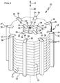
- FIG. 1 shows, in a schematic, simplified representation, an advantageous embodiment of a fuel cell device according to the invention, which is generally assigned the reference numeral 10.
- the fuel cell device 10 is referred to below in a simplified manner as the device 10.
- the device 10 comprises a plurality of fuel cells 12 which are arranged in stacks on top of one another and are preferably of identical design.
- the fuel cells are PEM fuel cells (polymer electrolyte fuel cells), in which hydrogen reacts with oxygen, producing water, waste heat and electrical energy.
- any feeds for hydrogen and oxygen and / or electrical lines for dissipating the electrical energy that occurs during the reaction are expediently provided that the oxygen can be taken from the surrounding medium, in the present case air, and that no separate supply is required.
- the fuel cells 12 are stacked one on top of the other along a stacking direction 14 and are arranged in such a way that the respective outer edges of the fuel cells 12 are aligned with one another and a uniform jacket surface 16 is formed on the outside.
- the fuel cell stack 18 formed by the fuel cells 12 has a first end side 20 and a second end side 22.
- the end sides 20, 22 are end sides of the fuel cell stack 18 facing away from one another.
- the fuel cell stack 18 has at least some, preferably all, of the fuel cells 12 penetrating recess 24 in the stacking direction 14.
- the recess 24 is formed as a through opening 26, which in the present case advantageously extends from the first end side 20 to the second end side 22.
- the through opening 26 is formed centrally in the fuel cell stack 18 and runs along the stacking direction 14, which defines an axis 28 of the fuel cell stack 18.
- a respective fuel cell 12 is configured in the shape of a ring and has a passage opening 30 in the center.
- the through openings 30 are aligned with one another and thereby form the through opening 26.
- An inner circumferential surface 32 of the fuel cell stack 18 encloses the through opening 26.
- the device 10 can be convectively cooled for cooling and setting an optimal operating point.
- cooling air is used, which flows around the fuel cell stack 18.
- the cooling air can flow through the through opening 26.
- the device 10 has at least one heat-conducting element 34 which is arranged in thermal contact with the fuel cells 12 in the recess 24 and in particular through opening 26.
- a plurality of heat conducting elements 34 are provided on the inner circumferential surface 32.
- a plurality of heat-conducting elements 34 are also provided on the jacket surface 16. It is favorable here that, on the one hand, the heat-conducting elements 34 in the through-opening 26 are configured identically for themselves and on the other hand on the lateral surface 16 for themselves. In the device 10, all of the heat-conducting elements 34 are even configured identically.
- the heat conducting elements 34 are designed as heat pipes 36 (heat pipes).
- a heat transfer medium is received in the heat pipes 36, which evaporates while absorbing heat and condenses again at another point.
- a continuous saturated steam region is established in the heat pipe 36, as a result of which a substantially constant temperature of the heat pipe 36 is promoted.
- the heat pipes 36 are convectively cooled by the flowing air, as a result of which heat can be effectively removed from the fuel cell stack 18 and a largely homogeneous temperature distribution can be achieved within a respective fuel cell 12. Due to the uniform temperature of the heat pipes 36 in each case, there is the advantage that no temperature gradient occurs within the fuel cell stack 18 in the stacking direction 14.
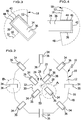
- the recess 24 has respective grooves 38.
- the grooves 38 are formed by recesses 40 on a respective fuel cell 12.
- the stacking of the fuel cells 12 results in the respective groove along the stacking direction 14.
- the strip-shaped and in particular cuboid-shaped heat pipe 36 is dimensioned such that it can engage positively in the groove 38.
- the heat pipe 36 extends from the first end side 20 to the second end side 22.
- the heat pipe 36 engages in the groove 38 with an engagement section.
- the other section of the heat pipe 36 protrudes from the groove 38.
- the heat pipe 36 engages approximately halfway into the groove 38. This ensures, on the one hand, effective heat transfer to the heat pipe 36 and, on the other hand, effective heat dissipation as a result of the air cooling.
- Grooves 38 for receiving a respective heat pipe 36 which correspond in size and structure to the grooves 38 on the inner circumferential surface 32, are also formed on the lateral surface 16.
- the present four heat pipes 36 are positioned equidistant from one another on the inner circumferential surface 32. In the present case, there is an angular distance between adjacent heat pipes 36 essentially 90 ° with respect to the axis 28.
- the present eight heat pipes 36 are positioned equidistant from one another on the lateral surface 16.
- An angular distance between adjacent heat pipes 36 with respect to the axis 28 is essentially 45 °.
- the heat pipes 36 on the inner circumferential surface 32 and on the jacket surface 16 have their greatest extent parallel to the axis 28. Their dimensions radially with respect to the axis 28 are greater than their dimensions with respect to the circumferential direction about the axis 28. In this way, the heat pipes 36 protrude, based on an axial direction of view in a plan view of the fuel cell stack 18 ( Figure 2 ) essentially radially inwards on the inner circumferential surface 32 or radially outwards on the jacket surface 16.
- a contact medium 44 in the form of a layer is provided in the present case.
- the contact medium 44 is formed, for example, by a thermally conductive paste 46 which covers the side walls and the bottom of the groove 38 and is in contact with the section of the heat pipe 36 which is immersed in the groove 38.
- the contact medium 44 also exercises a force-fit function in that adhesive forces act on the fuel cells 12 and / or on the heat pipe 36.
- thermally conductive elastomer can be used as the contact medium.
- a respective fuel cell 12 has a substantially octagonal outer contour 48 in the present axial view in plan view, ignoring the grooves 38.
- the inner contour 50 is also octagonal. Both Contours 48, 50 preferably have the contour of a regular octagon and, apart from the size, are congruent to one another.
- contours 48, 50 in other types of advantageous embodiments of the device 10 according to the invention can deviate from the shape described here.
- contours 48, 50 in other types of advantageous embodiments of the device 10 according to the invention can deviate from the shape described here.
- square, rectangular, round, in particular circular, polygonal or free-form contours are conceivable.
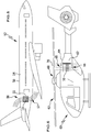
- FIGS 5 and 6 show advantageous embodiments of an aircraft according to the invention, assigned the reference symbols 52 and 60, respectively.
- the aircraft 52, 60 each have at least one device 10 of the type described above.
- the aircraft 52 is designed as a (jet) aircraft 54.
- the at least one device 10 is arranged in an interior space 55 which is delimited by a wall 56 of the fuselage.
- Inlet openings 57 and outlet openings 58 are arranged in the wall 56. Cooling air can flow through the inlet openings 57 into the interior space 55, flow along the device 10 and through the passage opening 26 and then exit again from the interior space 55 through the outlet openings 58.
- the openings 57, 58 are positioned and formed in such a way that the aerodynamic properties of the aircraft 54 are not impaired. In the present case, this is shown on the underside or the top of the fuselage.
- the aircraft 60 is a rotary wing aircraft 62 in the form of a helicopter.
- An interior space 63 is also provided, which is delimited by a wall 64, namely the motor housing of the helicopter.
- Inlet openings 65 and outlet openings 66 are formed in the wall 64.
- the at least one device 10 is positioned below a rotor 68 that generates lift and has blades 70.
- the downwash flow of the rotor 68 is used to cool the fuel cells 12 and can enter the interior 63 through the inlet opening 65 and then exit the interior 63 again through the outlet openings 66.
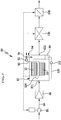
- FIG. 7 shows, with some components hidden, the conditioning device in a winter operating mode, Figure 8 in a summer operating mode.
- the conditioning device 80 comprises a chamber 82. At least one device 10 is arranged in the chamber 82. In the present case there are two of them.
- a feed line 84 is provided through which the medium can be conveyed by means of a conveying device 86, for example a blower.
- a filter element 88 can be connected upstream of the chamber 82 in the supply line 84.
- the medium is fed to the chamber 82.
- Oxygen contained in the air is used to react with hydrogen, which is supplied via a line not shown in the drawing.
- the chamber 82 has an inlet opening 831 for the medium and an outlet opening 832 for the medium.
- the fuel cells 12 are PEM fuel cells, in which, on the one hand, a specific moisture content and, on the other hand, a specific operating temperature should be set so that a preferred operating point is reached.
- Fuel cell exhaust gas is discharged from the chamber 82 via an outlet line 90.
- a suction unit 92 is provided in the present case in order to generate a negative pressure over the length of the fuel cell stack 18.
- the exhaust gas has a high water content (close to 100% relative humidity).
- a collecting device 94 is provided in order to remove water from the fuel cell exhaust gas.
- a droplet separator 96 is used (only in Figure 7 shown).
- the collecting device 94 has a reservoir 98 to which separated drops can be fed.
- the water is assigned to a spraying device 104 via a supply line 100 of the collecting device 94, into which a pump assembly 102 can be connected.
- the spray device 104 is arranged in the flow of the inflowing medium upstream of the device 10, so that the medium is moistened.
- the medium which is heated after passing through the fuel cell stack 18, passes through a cooling device 106, which can optionally be used in winter operation, to a heating device 108.
- the medium can be heated to the desired operating temperature.
- the drive for the conveying device 86, the suction unit 92, the pumping unit 102, the cooling device 106, the heating device 108 and internal units of the devices 10 can be operated electrically by means of the energy of the devices 10.
- the medium to be conditioned can be heated and the membranes of the fuel cells 12 can be moistened at the same time.
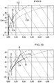
- Figure 9 shows an example of the process in winter operating mode, where the temperature (in ° C) is plotted against the humidity of the medium (in kg water / kg air).
- the curve provided with reference number 110 describes the equilibrium curve for 100% relative humidity, while the curve given reference number 112 describes the state of equilibrium for 50% relative humidity.
- preheating must first be carried out up to point B, then humidification to point C and finally reheating to point D (dotted curve 114).
- the step of preheating A-B and humidification B-C can be carried out simultaneously in the chamber 82, which is shown by the solid curve 116.
- the conditioning device 80 therefore also has the advantage over a conventional air conditioning system that the desired operating point D is reached more quickly.
- the medium to be conditioned and, in particular, to be cooled, namely air, is supplied via a separate supply line 118.
- a conveyor device 86 and a filter element 88 may be connected.
- the medium arrives at the cooling device 106 via the supply line 118.
- the cooling device 106 is preferably an air-conditioning device 120 which operates according to the heat pump principle.
- the fuel cell exhaust gas which is withdrawn from the chamber 82 via the outlet line 90, reaches the cooling device 106.
- the cooling device 106 forms part of the collecting device 94.
- the water contained in the exhaust gas condenses in the cooling device 106, for example on an air cooler.
- the water is fed to the reservoir 98 via a line 122 into which a pump assembly 124 can be connected. Starting from there, it can be used, as described above, to moisten the medium entering the chamber 82.
- the medium entering the chamber 82 is a process medium which, after flowing through and around the devices 10, is heated and is released into the atmosphere, for example, via a discharge line 126.
- the medium to be conditioned is supplied via the supply line 118.
- this air is dehumidified and cooled in a manner known per se. If necessary, reheating can take place in the heating device 108.
- Figure 10 shows the temperature as a function of the humidity for the summer operating mode according to Figure 8 .
- the warm and moderately humid air according to starting point A is cooled and dehumidified (BC) in the cooling device 106 along the curve 116.
- the cooled outside air is almost saturated with 100% relative humidity (B).
- B relative humidity
Landscapes
- Engineering & Computer Science (AREA)
- Chemical & Material Sciences (AREA)
- Life Sciences & Earth Sciences (AREA)
- Manufacturing & Machinery (AREA)
- Sustainable Development (AREA)
- Sustainable Energy (AREA)
- Chemical Kinetics & Catalysis (AREA)
- Electrochemistry (AREA)
- General Chemical & Material Sciences (AREA)
- Fuel Cell (AREA)
- Combustion & Propulsion (AREA)
Applications Claiming Priority (1)
| Application Number | Priority Date | Filing Date | Title |
|---|---|---|---|
| DE102019129336.7A DE102019129336A1 (de) | 2019-10-30 | 2019-10-30 | Brennstoffzellenvorrichtung, Fahrzeug mit Brennstoffzellenvorrichtung und Konditionierungsvorrichtung mit Brennstoffzellenvorrichtung |
Publications (2)
| Publication Number | Publication Date |
|---|---|
| EP3817112A1 true EP3817112A1 (fr) | 2021-05-05 |
| EP3817112B1 EP3817112B1 (fr) | 2024-05-01 |
Family
ID=73037883
Family Applications (1)
| Application Number | Title | Priority Date | Filing Date |
|---|---|---|---|
| EP20204521.7A Active EP3817112B1 (fr) | 2019-10-30 | 2020-10-29 | Pile à combustible, véhicule pourvu de dispositif de pile à combustible et dispositif de conditionnement pourvu de dispositif de pile à combustible |
Country Status (2)
| Country | Link |
|---|---|
| EP (1) | EP3817112B1 (fr) |
| DE (1) | DE102019129336A1 (fr) |
Families Citing this family (2)
| Publication number | Priority date | Publication date | Assignee | Title |
|---|---|---|---|---|
| CN115743564A (zh) * | 2022-12-17 | 2023-03-07 | 哈尔滨工业大学重庆研究院 | 一种带有燃料电堆动力系统的飞行器旋翼 |
| DE102023124704A1 (de) * | 2023-09-13 | 2025-03-13 | Aerostack GmbH | Brennstoffzellensystem mit wärmerohr |
Citations (3)
| Publication number | Priority date | Publication date | Assignee | Title |
|---|---|---|---|---|
| US20040053108A1 (en) * | 2002-08-28 | 2004-03-18 | Honda Giken Kogyo Kabushiki Kaisha | Fuel cell |
| KR20090006344A (ko) * | 2007-07-11 | 2009-01-15 | 현대자동차주식회사 | 센터 홀 타입 스택체결기구를 갖는 연료전지 스택 |
| US20190140289A1 (en) * | 2012-08-14 | 2019-05-09 | Loop Energy Inc. | Fuel Cell Components, Stacks and Modular Fuel Cell Systems |
Family Cites Families (3)
| Publication number | Priority date | Publication date | Assignee | Title |
|---|---|---|---|---|
| US6083636A (en) * | 1994-08-08 | 2000-07-04 | Ztek Corporation | Fuel cell stacks for ultra-high efficiency power systems |
| US6852439B2 (en) * | 2001-05-15 | 2005-02-08 | Hydrogenics Corporation | Apparatus for and method of forming seals in fuel cells and fuel cell stacks |
| DE102018208981B4 (de) * | 2018-06-07 | 2020-10-08 | Audi Ag | Brennstoffzellenvorrichtung |
-
2019
- 2019-10-30 DE DE102019129336.7A patent/DE102019129336A1/de not_active Ceased
-
2020
- 2020-10-29 EP EP20204521.7A patent/EP3817112B1/fr active Active
Patent Citations (3)
| Publication number | Priority date | Publication date | Assignee | Title |
|---|---|---|---|---|
| US20040053108A1 (en) * | 2002-08-28 | 2004-03-18 | Honda Giken Kogyo Kabushiki Kaisha | Fuel cell |
| KR20090006344A (ko) * | 2007-07-11 | 2009-01-15 | 현대자동차주식회사 | 센터 홀 타입 스택체결기구를 갖는 연료전지 스택 |
| US20190140289A1 (en) * | 2012-08-14 | 2019-05-09 | Loop Energy Inc. | Fuel Cell Components, Stacks and Modular Fuel Cell Systems |
Also Published As
| Publication number | Publication date |
|---|---|
| DE102019129336A1 (de) | 2021-05-06 |
| EP3817112B1 (fr) | 2024-05-01 |
Similar Documents
| Publication | Publication Date | Title |
|---|---|---|
| EP4193047A1 (fr) | Dispositif de traitement de gaz d'échappement pour moteur d'aéronef | |
| DE102006046114B4 (de) | Kühlanordnung zur Kühlung eines Wärmekörpers für ein Luftfahrzeug | |
| EP3817112B1 (fr) | Pile à combustible, véhicule pourvu de dispositif de pile à combustible et dispositif de conditionnement pourvu de dispositif de pile à combustible | |
| DE102011011032A1 (de) | Kompressorsystem mit einem freilaufenden Expander | |
| EP3844834B1 (fr) | Procédé pour augmenter la capacité de démarrage a froid et la capacité de commutation de charge et de performance de piles a combustible avec réduction simultané en oxygéné des gaz d'échappement du système | |
| DE102019216052A1 (de) | Kühlvorrichtung für eine Traktionsbatterie eines Fahrzeugs | |
| DE112022001934T5 (de) | Kühlungssystem | |
| DE102021200088A1 (de) | Luftversorgungseinrichtung für einen Flugzeug-Brennstoffzellen-Antrieb | |
| WO2021009150A1 (fr) | Système de refroidissement pour un empilement de piles à combustible | |
| DE102022214241A1 (de) | Befeuchtereinrichtung, Brennstoffzellensystem und Elektrofahrzeug | |
| EP3568901B1 (fr) | Machine électrique rotative | |
| DE112016005853B4 (de) | Gaszu- und -abführsystem | |
| DE102021204962A1 (de) | Kühlvorrichtung für eine Brennstoffzelle und Verfahren zum Betreiben einer Kühlvorrichtung | |
| DE102021202370A1 (de) | Verfahren zum Betreiben eines Brennstoffzellensystems, Brennstoffzellensystem | |
| EP3748252B1 (fr) | Appareil électrique | |
| DE102014209506A1 (de) | Brennstoffzellenvorrichtung mit Wärmeübertragungseinrichtung sowie Kraftfahrzeug mit Brennstoffzellenvorrichtung | |
| DE102018202691A1 (de) | Stromgeneratoranordnung mit Kühlsystem | |
| EP3396297A1 (fr) | Dispositif de refroidissement | |
| DE102021127498A1 (de) | Kühlsystem | |
| DE102023001013A1 (de) | Brennstoffzellensystem | |
| WO2022008189A1 (fr) | Dispositif de refroidissement pour refroidir un liquide de refroidissement pour un dispositif d'entraînement d'un véhicule automobile, procédé pour faire fonctionner un dispositif de refroidissement et dispositif de refroidissement pour un véhicule automobile | |
| DE102020002969A1 (de) | Kühlvorrichtung zur Batterie-Direktkühlung und Fahrzeug mit einer solchen Kühlvorrichtung | |
| DE102018131085A1 (de) | Ladeluftkühler (llk) mit einer kondensatdispersionsvorrichtung und ein verfahren zum dispergieren von kondensat eines llk | |
| DE102019205813A1 (de) | Brennstoffzellenstapel mit einer hygroskopischen Struktur | |
| WO2019233655A1 (fr) | Procédé d'humidification d'un réactif et système de pile à combustible permettant la mise en œuvre du procédé |
Legal Events
| Date | Code | Title | Description |
|---|---|---|---|
| PUAI | Public reference made under article 153(3) epc to a published international application that has entered the european phase |
Free format text: ORIGINAL CODE: 0009012 |
|
| STAA | Information on the status of an ep patent application or granted ep patent |
Free format text: STATUS: THE APPLICATION HAS BEEN PUBLISHED |
|
| AK | Designated contracting states |
Kind code of ref document: A1 Designated state(s): AL AT BE BG CH CY CZ DE DK EE ES FI FR GB GR HR HU IE IS IT LI LT LU LV MC MK MT NL NO PL PT RO RS SE SI SK SM TR |
|
| STAA | Information on the status of an ep patent application or granted ep patent |
Free format text: STATUS: REQUEST FOR EXAMINATION WAS MADE |
|
| 17P | Request for examination filed |
Effective date: 20211105 |
|
| RBV | Designated contracting states (corrected) |
Designated state(s): AL AT BE BG CH CY CZ DE DK EE ES FI FR GB GR HR HU IE IS IT LI LT LU LV MC MK MT NL NO PL PT RO RS SE SI SK SM TR |
|
| GRAP | Despatch of communication of intention to grant a patent |
Free format text: ORIGINAL CODE: EPIDOSNIGR1 |
|
| STAA | Information on the status of an ep patent application or granted ep patent |
Free format text: STATUS: GRANT OF PATENT IS INTENDED |
|
| INTG | Intention to grant announced |
Effective date: 20231128 |
|
| GRAS | Grant fee paid |
Free format text: ORIGINAL CODE: EPIDOSNIGR3 |
|
| GRAA | (expected) grant |
Free format text: ORIGINAL CODE: 0009210 |
|
| STAA | Information on the status of an ep patent application or granted ep patent |
Free format text: STATUS: THE PATENT HAS BEEN GRANTED |
|
| AK | Designated contracting states |
Kind code of ref document: B1 Designated state(s): AL AT BE BG CH CY CZ DE DK EE ES FI FR GB GR HR HU IE IS IT LI LT LU LV MC MK MT NL NO PL PT RO RS SE SI SK SM TR |
|
| REG | Reference to a national code |
Ref country code: GB Ref legal event code: FG4D Free format text: NOT ENGLISH |
|
| REG | Reference to a national code |
Ref country code: CH Ref legal event code: EP |
|
| REG | Reference to a national code |
Ref country code: DE Ref legal event code: R096 Ref document number: 502020007824 Country of ref document: DE |
|
| REG | Reference to a national code |
Ref country code: IE Ref legal event code: FG4D Free format text: LANGUAGE OF EP DOCUMENT: GERMAN |
|
| REG | Reference to a national code |
Ref country code: LT Ref legal event code: MG9D |
|
| REG | Reference to a national code |
Ref country code: NL Ref legal event code: MP Effective date: 20240501 |
|
| PG25 | Lapsed in a contracting state [announced via postgrant information from national office to epo] |
Ref country code: IS Free format text: LAPSE BECAUSE OF FAILURE TO SUBMIT A TRANSLATION OF THE DESCRIPTION OR TO PAY THE FEE WITHIN THE PRESCRIBED TIME-LIMIT Effective date: 20240901 |
|
| PG25 | Lapsed in a contracting state [announced via postgrant information from national office to epo] |
Ref country code: BG Free format text: LAPSE BECAUSE OF FAILURE TO SUBMIT A TRANSLATION OF THE DESCRIPTION OR TO PAY THE FEE WITHIN THE PRESCRIBED TIME-LIMIT Effective date: 20240501 |
|
| PG25 | Lapsed in a contracting state [announced via postgrant information from national office to epo] |
Ref country code: FI Free format text: LAPSE BECAUSE OF FAILURE TO SUBMIT A TRANSLATION OF THE DESCRIPTION OR TO PAY THE FEE WITHIN THE PRESCRIBED TIME-LIMIT Effective date: 20240501 Ref country code: HR Free format text: LAPSE BECAUSE OF FAILURE TO SUBMIT A TRANSLATION OF THE DESCRIPTION OR TO PAY THE FEE WITHIN THE PRESCRIBED TIME-LIMIT Effective date: 20240501 |
|
| PG25 | Lapsed in a contracting state [announced via postgrant information from national office to epo] |
Ref country code: GR Free format text: LAPSE BECAUSE OF FAILURE TO SUBMIT A TRANSLATION OF THE DESCRIPTION OR TO PAY THE FEE WITHIN THE PRESCRIBED TIME-LIMIT Effective date: 20240802 |
|
| PG25 | Lapsed in a contracting state [announced via postgrant information from national office to epo] |
Ref country code: PT Free format text: LAPSE BECAUSE OF FAILURE TO SUBMIT A TRANSLATION OF THE DESCRIPTION OR TO PAY THE FEE WITHIN THE PRESCRIBED TIME-LIMIT Effective date: 20240902 |
|
| PG25 | Lapsed in a contracting state [announced via postgrant information from national office to epo] |
Ref country code: NL Free format text: LAPSE BECAUSE OF FAILURE TO SUBMIT A TRANSLATION OF THE DESCRIPTION OR TO PAY THE FEE WITHIN THE PRESCRIBED TIME-LIMIT Effective date: 20240501 |
|
| PG25 | Lapsed in a contracting state [announced via postgrant information from national office to epo] |
Ref country code: ES Free format text: LAPSE BECAUSE OF FAILURE TO SUBMIT A TRANSLATION OF THE DESCRIPTION OR TO PAY THE FEE WITHIN THE PRESCRIBED TIME-LIMIT Effective date: 20240501 |
|
| PG25 | Lapsed in a contracting state [announced via postgrant information from national office to epo] |
Ref country code: PL Free format text: LAPSE BECAUSE OF FAILURE TO SUBMIT A TRANSLATION OF THE DESCRIPTION OR TO PAY THE FEE WITHIN THE PRESCRIBED TIME-LIMIT Effective date: 20240501 |
|
| PG25 | Lapsed in a contracting state [announced via postgrant information from national office to epo] |
Ref country code: LV Free format text: LAPSE BECAUSE OF FAILURE TO SUBMIT A TRANSLATION OF THE DESCRIPTION OR TO PAY THE FEE WITHIN THE PRESCRIBED TIME-LIMIT Effective date: 20240501 |
|
| PG25 | Lapsed in a contracting state [announced via postgrant information from national office to epo] |
Ref country code: PT Free format text: LAPSE BECAUSE OF FAILURE TO SUBMIT A TRANSLATION OF THE DESCRIPTION OR TO PAY THE FEE WITHIN THE PRESCRIBED TIME-LIMIT Effective date: 20240902 Ref country code: PL Free format text: LAPSE BECAUSE OF FAILURE TO SUBMIT A TRANSLATION OF THE DESCRIPTION OR TO PAY THE FEE WITHIN THE PRESCRIBED TIME-LIMIT Effective date: 20240501 Ref country code: NO Free format text: LAPSE BECAUSE OF FAILURE TO SUBMIT A TRANSLATION OF THE DESCRIPTION OR TO PAY THE FEE WITHIN THE PRESCRIBED TIME-LIMIT Effective date: 20240801 Ref country code: NL Free format text: LAPSE BECAUSE OF FAILURE TO SUBMIT A TRANSLATION OF THE DESCRIPTION OR TO PAY THE FEE WITHIN THE PRESCRIBED TIME-LIMIT Effective date: 20240501 Ref country code: LV Free format text: LAPSE BECAUSE OF FAILURE TO SUBMIT A TRANSLATION OF THE DESCRIPTION OR TO PAY THE FEE WITHIN THE PRESCRIBED TIME-LIMIT Effective date: 20240501 Ref country code: IS Free format text: LAPSE BECAUSE OF FAILURE TO SUBMIT A TRANSLATION OF THE DESCRIPTION OR TO PAY THE FEE WITHIN THE PRESCRIBED TIME-LIMIT Effective date: 20240901 Ref country code: HR Free format text: LAPSE BECAUSE OF FAILURE TO SUBMIT A TRANSLATION OF THE DESCRIPTION OR TO PAY THE FEE WITHIN THE PRESCRIBED TIME-LIMIT Effective date: 20240501 Ref country code: GR Free format text: LAPSE BECAUSE OF FAILURE TO SUBMIT A TRANSLATION OF THE DESCRIPTION OR TO PAY THE FEE WITHIN THE PRESCRIBED TIME-LIMIT Effective date: 20240802 Ref country code: FI Free format text: LAPSE BECAUSE OF FAILURE TO SUBMIT A TRANSLATION OF THE DESCRIPTION OR TO PAY THE FEE WITHIN THE PRESCRIBED TIME-LIMIT Effective date: 20240501 Ref country code: ES Free format text: LAPSE BECAUSE OF FAILURE TO SUBMIT A TRANSLATION OF THE DESCRIPTION OR TO PAY THE FEE WITHIN THE PRESCRIBED TIME-LIMIT Effective date: 20240501 Ref country code: BG Free format text: LAPSE BECAUSE OF FAILURE TO SUBMIT A TRANSLATION OF THE DESCRIPTION OR TO PAY THE FEE WITHIN THE PRESCRIBED TIME-LIMIT Effective date: 20240501 Ref country code: RS Free format text: LAPSE BECAUSE OF FAILURE TO SUBMIT A TRANSLATION OF THE DESCRIPTION OR TO PAY THE FEE WITHIN THE PRESCRIBED TIME-LIMIT Effective date: 20240801 |
|
| PG25 | Lapsed in a contracting state [announced via postgrant information from national office to epo] |
Ref country code: DK Free format text: LAPSE BECAUSE OF FAILURE TO SUBMIT A TRANSLATION OF THE DESCRIPTION OR TO PAY THE FEE WITHIN THE PRESCRIBED TIME-LIMIT Effective date: 20240501 |
|
| PG25 | Lapsed in a contracting state [announced via postgrant information from national office to epo] |
Ref country code: EE Free format text: LAPSE BECAUSE OF FAILURE TO SUBMIT A TRANSLATION OF THE DESCRIPTION OR TO PAY THE FEE WITHIN THE PRESCRIBED TIME-LIMIT Effective date: 20240501 |
|
| PG25 | Lapsed in a contracting state [announced via postgrant information from national office to epo] |
Ref country code: CZ Free format text: LAPSE BECAUSE OF FAILURE TO SUBMIT A TRANSLATION OF THE DESCRIPTION OR TO PAY THE FEE WITHIN THE PRESCRIBED TIME-LIMIT Effective date: 20240501 |
|
| PG25 | Lapsed in a contracting state [announced via postgrant information from national office to epo] |
Ref country code: SK Free format text: LAPSE BECAUSE OF FAILURE TO SUBMIT A TRANSLATION OF THE DESCRIPTION OR TO PAY THE FEE WITHIN THE PRESCRIBED TIME-LIMIT Effective date: 20240501 Ref country code: RO Free format text: LAPSE BECAUSE OF FAILURE TO SUBMIT A TRANSLATION OF THE DESCRIPTION OR TO PAY THE FEE WITHIN THE PRESCRIBED TIME-LIMIT Effective date: 20240501 |
|
| PG25 | Lapsed in a contracting state [announced via postgrant information from national office to epo] |
Ref country code: SM Free format text: LAPSE BECAUSE OF FAILURE TO SUBMIT A TRANSLATION OF THE DESCRIPTION OR TO PAY THE FEE WITHIN THE PRESCRIBED TIME-LIMIT Effective date: 20240501 |
|
| PG25 | Lapsed in a contracting state [announced via postgrant information from national office to epo] |
Ref country code: SM Free format text: LAPSE BECAUSE OF FAILURE TO SUBMIT A TRANSLATION OF THE DESCRIPTION OR TO PAY THE FEE WITHIN THE PRESCRIBED TIME-LIMIT Effective date: 20240501 Ref country code: SK Free format text: LAPSE BECAUSE OF FAILURE TO SUBMIT A TRANSLATION OF THE DESCRIPTION OR TO PAY THE FEE WITHIN THE PRESCRIBED TIME-LIMIT Effective date: 20240501 Ref country code: RO Free format text: LAPSE BECAUSE OF FAILURE TO SUBMIT A TRANSLATION OF THE DESCRIPTION OR TO PAY THE FEE WITHIN THE PRESCRIBED TIME-LIMIT Effective date: 20240501 Ref country code: EE Free format text: LAPSE BECAUSE OF FAILURE TO SUBMIT A TRANSLATION OF THE DESCRIPTION OR TO PAY THE FEE WITHIN THE PRESCRIBED TIME-LIMIT Effective date: 20240501 Ref country code: DK Free format text: LAPSE BECAUSE OF FAILURE TO SUBMIT A TRANSLATION OF THE DESCRIPTION OR TO PAY THE FEE WITHIN THE PRESCRIBED TIME-LIMIT Effective date: 20240501 Ref country code: CZ Free format text: LAPSE BECAUSE OF FAILURE TO SUBMIT A TRANSLATION OF THE DESCRIPTION OR TO PAY THE FEE WITHIN THE PRESCRIBED TIME-LIMIT Effective date: 20240501 |
|
| REG | Reference to a national code |
Ref country code: DE Ref legal event code: R097 Ref document number: 502020007824 Country of ref document: DE |
|
| PG25 | Lapsed in a contracting state [announced via postgrant information from national office to epo] |
Ref country code: IT Free format text: LAPSE BECAUSE OF FAILURE TO SUBMIT A TRANSLATION OF THE DESCRIPTION OR TO PAY THE FEE WITHIN THE PRESCRIBED TIME-LIMIT Effective date: 20240501 |
|
| PLBE | No opposition filed within time limit |
Free format text: ORIGINAL CODE: 0009261 |
|
| STAA | Information on the status of an ep patent application or granted ep patent |
Free format text: STATUS: NO OPPOSITION FILED WITHIN TIME LIMIT |
|
| 26N | No opposition filed |
Effective date: 20250204 |
|
| PG25 | Lapsed in a contracting state [announced via postgrant information from national office to epo] |
Ref country code: SI Free format text: LAPSE BECAUSE OF FAILURE TO SUBMIT A TRANSLATION OF THE DESCRIPTION OR TO PAY THE FEE WITHIN THE PRESCRIBED TIME-LIMIT Effective date: 20240501 |
|
| REG | Reference to a national code |
Ref country code: CH Ref legal event code: PL |
|
| GBPC | Gb: european patent ceased through non-payment of renewal fee |
Effective date: 20241029 |
|
| PG25 | Lapsed in a contracting state [announced via postgrant information from national office to epo] |
Ref country code: MC Free format text: LAPSE BECAUSE OF FAILURE TO SUBMIT A TRANSLATION OF THE DESCRIPTION OR TO PAY THE FEE WITHIN THE PRESCRIBED TIME-LIMIT Effective date: 20240501 |
|
| PG25 | Lapsed in a contracting state [announced via postgrant information from national office to epo] |
Ref country code: GB Free format text: LAPSE BECAUSE OF NON-PAYMENT OF DUE FEES Effective date: 20241029 |
|
| PG25 | Lapsed in a contracting state [announced via postgrant information from national office to epo] |
Ref country code: LU Free format text: LAPSE BECAUSE OF NON-PAYMENT OF DUE FEES Effective date: 20241029 Ref country code: BE Free format text: LAPSE BECAUSE OF NON-PAYMENT OF DUE FEES Effective date: 20241031 |
|
| PG25 | Lapsed in a contracting state [announced via postgrant information from national office to epo] |
Ref country code: FR Free format text: LAPSE BECAUSE OF NON-PAYMENT OF DUE FEES Effective date: 20241031 |
|
| PG25 | Lapsed in a contracting state [announced via postgrant information from national office to epo] |
Ref country code: CH Free format text: LAPSE BECAUSE OF NON-PAYMENT OF DUE FEES Effective date: 20241031 |
|
| REG | Reference to a national code |
Ref country code: BE Ref legal event code: MM Effective date: 20241031 |
|
| PG25 | Lapsed in a contracting state [announced via postgrant information from national office to epo] |
Ref country code: SE Free format text: LAPSE BECAUSE OF FAILURE TO SUBMIT A TRANSLATION OF THE DESCRIPTION OR TO PAY THE FEE WITHIN THE PRESCRIBED TIME-LIMIT Effective date: 20240501 |
|
| PG25 | Lapsed in a contracting state [announced via postgrant information from national office to epo] |
Ref country code: IE Free format text: LAPSE BECAUSE OF NON-PAYMENT OF DUE FEES Effective date: 20241029 |
|
| PGFP | Annual fee paid to national office [announced via postgrant information from national office to epo] |
Ref country code: DE Payment date: 20250912 Year of fee payment: 6 |
|
| PGFP | Annual fee paid to national office [announced via postgrant information from national office to epo] |
Ref country code: AT Payment date: 20260113 Year of fee payment: 5 |
|
| PG25 | Lapsed in a contracting state [announced via postgrant information from national office to epo] |
Ref country code: HU Free format text: LAPSE BECAUSE OF FAILURE TO SUBMIT A TRANSLATION OF THE DESCRIPTION OR TO PAY THE FEE WITHIN THE PRESCRIBED TIME-LIMIT; INVALID AB INITIO Effective date: 20201029 |
|
| PG25 | Lapsed in a contracting state [announced via postgrant information from national office to epo] |
Ref country code: CY Free format text: LAPSE BECAUSE OF FAILURE TO SUBMIT A TRANSLATION OF THE DESCRIPTION OR TO PAY THE FEE WITHIN THE PRESCRIBED TIME-LIMIT; INVALID AB INITIO Effective date: 20201029 |