EP3817123B1 - Elektrodenanordnung und wiederaufladbare batterie damit - Google Patents
Elektrodenanordnung und wiederaufladbare batterie damit Download PDFInfo
- Publication number
- EP3817123B1 EP3817123B1 EP19837600.6A EP19837600A EP3817123B1 EP 3817123 B1 EP3817123 B1 EP 3817123B1 EP 19837600 A EP19837600 A EP 19837600A EP 3817123 B1 EP3817123 B1 EP 3817123B1
- Authority
- EP
- European Patent Office
- Prior art keywords
- positive electrode
- negative electrode
- coating portion
- disposed
- sheet
- Prior art date
- Legal status (The legal status is an assumption and is not a legal conclusion. Google has not performed a legal analysis and makes no representation as to the accuracy of the status listed.)
- Active
Links
Images


Classifications
-
- H—ELECTRICITY
- H01—ELECTRIC ELEMENTS
- H01M—PROCESSES OR MEANS, e.g. BATTERIES, FOR THE DIRECT CONVERSION OF CHEMICAL ENERGY INTO ELECTRICAL ENERGY
- H01M10/00—Secondary cells; Manufacture thereof
- H01M10/04—Construction or manufacture in general
- H01M10/0431—Cells with wound or folded electrodes
-
- H—ELECTRICITY
- H01—ELECTRIC ELEMENTS
- H01M—PROCESSES OR MEANS, e.g. BATTERIES, FOR THE DIRECT CONVERSION OF CHEMICAL ENERGY INTO ELECTRICAL ENERGY
- H01M10/00—Secondary cells; Manufacture thereof
- H01M10/05—Accumulators with non-aqueous electrolyte
- H01M10/052—Li-accumulators
- H01M10/0525—Rocking-chair batteries, i.e. batteries with lithium insertion or intercalation in both electrodes; Lithium-ion batteries
-
- H—ELECTRICITY
- H01—ELECTRIC ELEMENTS
- H01M—PROCESSES OR MEANS, e.g. BATTERIES, FOR THE DIRECT CONVERSION OF CHEMICAL ENERGY INTO ELECTRICAL ENERGY
- H01M10/00—Secondary cells; Manufacture thereof
- H01M10/05—Accumulators with non-aqueous electrolyte
- H01M10/058—Construction or manufacture
- H01M10/0587—Construction or manufacture of accumulators having only wound construction elements, i.e. wound positive electrodes, wound negative electrodes and wound separators
-
- H—ELECTRICITY
- H01—ELECTRIC ELEMENTS
- H01M—PROCESSES OR MEANS, e.g. BATTERIES, FOR THE DIRECT CONVERSION OF CHEMICAL ENERGY INTO ELECTRICAL ENERGY
- H01M50/00—Constructional details or processes of manufacture of the non-active parts of electrochemical cells other than fuel cells, e.g. hybrid cells
- H01M50/10—Primary casings; Jackets or wrappings
- H01M50/102—Primary casings; Jackets or wrappings characterised by their shape or physical structure
- H01M50/107—Primary casings; Jackets or wrappings characterised by their shape or physical structure having curved cross-section, e.g. round or elliptic
-
- H—ELECTRICITY
- H01—ELECTRIC ELEMENTS
- H01M—PROCESSES OR MEANS, e.g. BATTERIES, FOR THE DIRECT CONVERSION OF CHEMICAL ENERGY INTO ELECTRICAL ENERGY
- H01M50/00—Constructional details or processes of manufacture of the non-active parts of electrochemical cells other than fuel cells, e.g. hybrid cells
- H01M50/50—Current conducting connections for cells or batteries
- H01M50/531—Electrode connections inside a battery casing
-
- H—ELECTRICITY
- H01—ELECTRIC ELEMENTS
- H01M—PROCESSES OR MEANS, e.g. BATTERIES, FOR THE DIRECT CONVERSION OF CHEMICAL ENERGY INTO ELECTRICAL ENERGY
- H01M50/00—Constructional details or processes of manufacture of the non-active parts of electrochemical cells other than fuel cells, e.g. hybrid cells
- H01M50/50—Current conducting connections for cells or batteries
- H01M50/531—Electrode connections inside a battery casing
- H01M50/538—Connection of several leads or tabs of wound or folded electrode stacks
-
- H—ELECTRICITY
- H01—ELECTRIC ELEMENTS
- H01M—PROCESSES OR MEANS, e.g. BATTERIES, FOR THE DIRECT CONVERSION OF CHEMICAL ENERGY INTO ELECTRICAL ENERGY
- H01M50/00—Constructional details or processes of manufacture of the non-active parts of electrochemical cells other than fuel cells, e.g. hybrid cells
- H01M50/50—Current conducting connections for cells or batteries
- H01M50/572—Means for preventing undesired use or discharge
- H01M50/584—Means for preventing undesired use or discharge for preventing incorrect connections inside or outside the batteries
- H01M50/59—Means for preventing undesired use or discharge for preventing incorrect connections inside or outside the batteries characterised by the protection means
- H01M50/595—Tapes
-
- Y—GENERAL TAGGING OF NEW TECHNOLOGICAL DEVELOPMENTS; GENERAL TAGGING OF CROSS-SECTIONAL TECHNOLOGIES SPANNING OVER SEVERAL SECTIONS OF THE IPC; TECHNICAL SUBJECTS COVERED BY FORMER USPC CROSS-REFERENCE ART COLLECTIONS [XRACs] AND DIGESTS
- Y02—TECHNOLOGIES OR APPLICATIONS FOR MITIGATION OR ADAPTATION AGAINST CLIMATE CHANGE
- Y02E—REDUCTION OF GREENHOUSE GAS [GHG] EMISSIONS, RELATED TO ENERGY GENERATION, TRANSMISSION OR DISTRIBUTION
- Y02E60/00—Enabling technologies; Technologies with a potential or indirect contribution to GHG emissions mitigation
- Y02E60/10—Energy storage using batteries
-
- Y—GENERAL TAGGING OF NEW TECHNOLOGICAL DEVELOPMENTS; GENERAL TAGGING OF CROSS-SECTIONAL TECHNOLOGIES SPANNING OVER SEVERAL SECTIONS OF THE IPC; TECHNICAL SUBJECTS COVERED BY FORMER USPC CROSS-REFERENCE ART COLLECTIONS [XRACs] AND DIGESTS
- Y02—TECHNOLOGIES OR APPLICATIONS FOR MITIGATION OR ADAPTATION AGAINST CLIMATE CHANGE
- Y02P—CLIMATE CHANGE MITIGATION TECHNOLOGIES IN THE PRODUCTION OR PROCESSING OF GOODS
- Y02P70/00—Climate change mitigation technologies in the production process for final industrial or consumer products
- Y02P70/50—Manufacturing or production processes characterised by the final manufactured product
Definitions
- Secondary batteries are rechargeable unlike primarily batteries, and also, the possibility of compact size and high capacity is high. Thus, recently, many studies on rechargeable batteries are being carried out. As technology development and demands for mobile devices increase, the demands for rechargeable batteries as energy sources are rapidly increasing.
- another aspect of the present invention is to provide an electrode assembly that is capable of minimizing a capacity loss and a secondary battery comprising the same.
- a secondary battery comprises an electrode assembly and a battery case configured to accommodate the electrode assembly, wherein the electrode assembly comprises: a positive electrode sheet comprising a positive electrode collector, a positive electrode active material stacked on the positive electrode collector, and a positive electrode non-coating portion that is an area on which the positive electrode active material is not stacked; a positive electrode tab disposed on the positive electrode non-coating portion; a negative electrode sheet comprising a negative electrode collector, a negative electrode active material stacked on the negative electrode collector, and a negative electrode non-coating portion that is an area on which the negative electrode active material is not stacked; a negative electrode tab disposed on the negative electrode sheet; and a separator configured to insulate the positive electrode sheet and the negative electrode sheet from each other, wherein the positive electrode non-coating portion comprises a first positive electrode non-coating portion and a second positive electrode non-coating portion, which are provided on two portions on the positive electrode sheet, the negative electrode non-
- the number of electrode tabs may increase to reduce the resistance.
- the number of negative electrode tabs may increase so that the number of negative electrode tabs is larger than that of positive electrode tabs, thereby minimizing the resistance.
- an electrode assembly 100 comprises a positive electrode sheet 110 comprising a positive electrode active material portion 112 and a positive electrode non-coating portion 113, a positive electrode tab 150 provided on the positive electrode non-coating portion 113, a negative electrode sheet 120 comprising a negative electrode active material portion 122 and a negative electrode non-coating portion 123, a negative electrode tab 160 provided on the negative electrode non-coating portion 123, and a separator 140 provided between the positive electrode sheet 110 and the negative electrode sheet 120.
- the electrode 130 comprises the positive electrode sheet 110 and the negative electrode sheet 120. Also, the separator 140 may electrically insulate the positive electrode sheet 110 from the negative electrode sheet 120.
- the positive electrode sheet 110 and the negative electrode sheet 120 are alternately stacked and wound together with the separator 140 and may be formed in a roll shape.
- the electrode assembly 100 may be, for example, wound in a circular or oval shape so as to be formed in a jelly roll type.
- the positive electrode sheet 110 comprises a positive electrode active material portion 112 that is an area on which a positive electrode active material is stacked on a positive electrode collector 111 and a positive electrode non-coating portion 113 that is an area on which a positive electrode active material is not stacked.
- the positive electrode sheet 110 may be disposed, for example, in the form of a sheet.
- the positive electrode collector 111 may be provided as foil made of an aluminum (Al) material.
- the positive electrode active material portion 112 may comprise a positive electrode active material stacked on one or more surfaces of one surface 110c or the other surface 110d of the positive electrode sheet 110.
- the positive electrode active material portion 112 may be disposed, for example, on both surfaces of the positive electrode sheet 120.
- the positive electrode active material portion 112 may further comprise a binder and a conductive material in addition to the positive electrode active material.
- the binder may comprise one of polyfluoro vinylidene, polyvinyl alcohol, carboxymethyl cellulose (CMC), starch, hydroxypropyl cellulose, regenerated cellulose, polyvinyl pyrrolidone, tetrafluoroethylene, polyethylene, polypropylene, ethylene-propylene-diene terpolymer (EPDM), sulfonated EPDM, styrene butadiene rubber, and fluoro rubber.
- CMC carboxymethyl cellulose
- EPDM ethylene-propylene-diene terpolymer
- EPDM ethylene-propylene-diene terpolymer
- EPDM ethylene-propylene-diene terpolymer
- sulfonated EPDM styrene butadiene rubber
- fluoro rubber fluoro rubber
- the first positive electrode non-coating portion 113a and the second positive electrode non-coating portion 113b are disposed between both sides in a longitudinal direction of the positive electrode sheet 110.
- the first positive electrode non-coating portion 113a may be disposed close to one side portion 110a of the positive electrode sheet 110
- the second positive electrode non-coating portion 113b may be disposed close to the other side portion 110b of the positive electrode sheet 110.
- first positive electrode non-coating portion 113a may be disposed at a side of a winding outer portion, and the second positive electrode non-coating portion 113b may be disposed at a side of a winding central portion when the positive electrode sheet 110 is wound.
- the present invention is not necessarily limited thereto.
- the first positive electrode non-coating portion 113a may be disposed at the side of the winding central portion, and the second positive electrode non-coating portion 113b may be disposed at the side of the winding outer portion when the positive electrode sheet 110 is wound.
- the positive electrode tab 150 is provided on the positive electrode non-coating portion 113 of the positive electrode sheet 110.
- one end of the positive electrode tab 150 may be attached and fixed to the positive electrode non-coating portion 113, and the other end of the positive electrode tab 150 may protrude from the positive electrode sheet 110.
- the positive electrode tab 150 comprises a first positive electrode tab 151 provided on the first positive electrode non-coating portion 113a and a second positive electrode tab 152 provided on the second positive electrode non-coating portion 113b.
- first positive electrode tab 151 and the second positive electrode tab 152 are illustrated as being disposed on the other surface 110d of the positive electrode sheet 110 in FIG. 3 , the present invention is not necessarily limited thereto.
- the first positive electrode tab 151 and the second positive electrode tab 152 may be disposed on one surface 110c or the other surface 110d of the positive electrode sheet 110, respectively.
- the first positive electrode tab 151 and the second positive electrode tab 152 may be disposed on the one surface 110c of the positive electrode sheet 110.
- the first positive electrode tab 151 and the second positive electrode tab 152 may be disposed at both sides of a winding central axis C in the wound electrode assembly 100.
- the negative electrode sheet 120 comprises a negative electrode active material portion 122 that is an area on which a negative electrode active material is stacked on the negative electrode collector 121 and a negative electrode non-coating portion 123 that is an area on which the negative electrode active material is not stacked.
- the negative electrode sheet 120 may is provided in, for example, the form of a sheet.
- the negative electrode active material may be made of a material comprising synthetic graphite.
- the negative electrode active material may comprise lithium a metal, a lithium alloy, carbon, petroleum coke, activated carbon, graphite, a silicon compound, a tin compound, a titanium compound, or an alloy thereof.
- the negative electrode non-coating portion 123 comprises a first negative electrode non-coating portion 123a disposed between both sides in a longitudinal direction of the negative electrode sheet 120 and second and third negative electrode non-coating portions 123b and 123c disposed at both sides of the negative electrode sheet 120.
- the negative electrode non-coating portion 123 may be disposed on at least one surface of both surfaces of the negative electrode sheet 120.
- the first positive electrode non-coating portion 113a and the first negative electrode non-coating portion 123a are disposed at positions corresponding to each other.
- the negative electrode tab 160 is disposed on the negative electrode non-coating portion 123.
- one end of the negative electrode tab 160 may be attached and fixed to the negative electrode non-coating portion 123, and the other end of the negative electrode tab 160 may protrude from the negative electrode sheet 120.
- the negative electrode tab 160 comprise a first negative electrode tab 161 provided on the first negative electrode non-coating portion 123a, a second negative electrode tab 162 provided on the second negative electrode non-coating portion 123b, and a third negative electrode tab 163 disposed on the third negative electrode non-coating portion 123c.
- the first negative electrode tab 161 and the second negative electrode tab 162 are illustrated as being disposed on the one surface 120c of the negative electrode sheet 120 in FIG. 3 , the present invention is not necessarily limited thereto.
- the first negative electrode tab 161, the second negative electrode tab 162, and the third negative electrode tab 163 may be disposed on the one surface 120c or the other surface 120d of the negative electrode sheet 120, respectively.
- the first negative electrode tab 161 and the second negative electrode tab 162 may be disposed on the other surface 120d of the negative electrode sheet 120
- the third negative electrode tab 163 may be disposed on one surface 120c of the negative electrode sheet 120.
- the positive electrode insulation tape 170 and the negative electrode insulation tape 180 may comprise, for example, a base material (not shown) and an adhesion layer (not shown) disposed on one surface of the base material.
- a lithium ion deposition prevention tape 190 is further attached on a portion of the positive electrode sheet 110 which faces the first negative electrode insulation tape 181 with the separator 140 therebetween.
- the lithium ion deposition prevention tape 190 may be provided on, for example, the other surface 110d of the positive electrode sheet 110, particularly, disposed on a surface of the positive electrode active material 112 stacked between the one side portion 110a of the positive electrode sheet 110 and the first positive electrode non-coating portion 113a that is disposed close to the one side portion 110a of the positive electrode sheet 110.
- the lithium ion deposition prevention tape 190 and the first negative electrode non-coating portion 123a may face each other with the second separator 142 therebetween.
- the lithium ion deposition prevention tape 190 may be made of an electrical insulation material.
- the lithium ion deposition prevention tape 190 is disposed on a portion of the positive electrode sheet 110 facing the first negative electrode non-coating portion 123a, to which the first negative electrode insulation tape 181 is attached, to prevent lithium ions, which are not exchanged, from being accumulated to be deposited during the charging and discharging.
- the lithium ion deposition prevention tape 190 is attached to the surface of the positive electrode active material portion 112 of the positive electrode sheet 110 facing the first negative electrode insulation tape 181 to prevent the lithium ions from being accumulated to be deposited on the portion at which the lithium ions are not exchanged by the first negative electrode insulation tape 181 when the lithium ion are exchanged to perform the charging and the discharging.
- the lithium ion deposition prevention tape 190 may be made of, for example, polyimide (PI).
- the electrode assembly 100 may reduce resistance by adding the first negative electrode tab 161 such that the number of negative electrode tabs 160 is greater than that of the positive electrode tabs 150.
- FIG. 7 is a front view illustrating an unfolded state before an electrode assembly is wound according to a second embodiment of the present invention.
- the positive electrode non-coating portion 213 may be divided into two portions spaced apart from each other and thus comprises a first positive electrode non-coating portion 213a and a second positive electrode non-coating portion 213b.
- the positive electrode non-coating portion 213 may be disposed on at least one surface of both surfaces of the positive electrode sheet 210.
- the first positive electrode non-coating portion 213a and the second positive electrode non-coating portion 213b may be disposed between both sides in a longitudinal direction of the positive electrode sheet 210.
- first positive electrode non-coating portion 213a may be disposed at a side of a winding outer portion
- the second positive electrode non-coating portion 213b may be disposed at a side of a winding central portion when the positive electrode sheet 210 is wound.
- the present invention is not necessarily limited thereto.
- the first positive electrode non-coating portion 213a may be disposed at the side of the winding central portion
- the second positive electrode non-coating portion 213b may be disposed at the side of the winding outer portion when the positive electrode sheet 210 is wound.
- the positive electrode tab 250 may comprise a first positive electrode tab 251 provided on the first positive electrode non-coating portion 213a and a second positive electrode tab 252 provided on the second positive electrode non-coating portion 213b.
- the negative electrode sheet 220 may comprise a negative electrode active material portion 222 that is an area on which a negative electrode active material is stacked on the negative electrode collector 221 and a negative electrode non-coating portion 223 that is an area on which the negative electrode active material is not stacked.
- the negative electrode non-coating portion 223 comprises a first negative electrode non-coating portion 223a disposed between both sides in a longitudinal direction of the negative electrode sheet 220 and second and third negative electrode non-coating portions 223b and 223c disposed at both sides of the negative electrode sheet 220.
- the negative electrode non-coating portion 223 may be disposed on at least one surface of both surfaces of the negative electrode sheet 220.
- the second positive electrode non-coating portion 213b and the first negative electrode non-coating portion 223a are disposed corresponding to each other.
- the negative electrode tab 260 is disposed on the negative electrode non-coating portion 223.
- one end of the negative electrode tab 260 may be attached and fixed to the negative electrode non-coating portion 223, and the other end of the negative electrode tab 160 may protrude from the negative electrode sheet 220.
- a positive electrode insulation tape 270 may be further attached to the positive electrode non-coating portion 213 to cover the positive electrode tab 250, and a negative electrode insulation tape 280 may be further attached to the negative electrode non-coating portion 223 to cover the negative electrode tab 260.
- the positive electrode insulation tape 270 may comprise a first positive electrode insulation tape 271 attached to the first positive electrode non-coating portion 213a to cover the first positive electrode tab 251 and a second positive electrode insulation tape 272 attached to the second positive electrode non-coating portion 213b to cover the second positive electrode tab 252.
- the negative electrode insulation tape 280 comprises a first negative electrode insulation tape 281 attached to the first negative electrode non-coating portion 223a to cover the first negative electrode tab 261.
- a second negative electrode insulation tape 282 may be attached to the second negative electrode non-coating portion 223b to the second negative electrode tab 262, and a third negative electrode insulation tape 283 may be attached to the third negative electrode non-coating portion 223c to cover the third negative electrode tab 263.
- the negative electrode insulation tape 280 may further comprise a fourth negative electrode insulation tape 284 attached to a surface opposite to the surface on which the second negative electrode tab 262 is disposed on the second negative electrode non-coating portion 223b.
- the electrode assembly 300 according to the third embodiment of the present invention is different from the electrode assembly 100 according to the first embodiment and the electrode assembly according to the second embodiment in winding shape.
- this embodiment briefly describes the contents overlapping with the above-described embodiment and will be described based on the differences.
- the positive electrode sheet 310 comprises a positive electrode active material portion 312 that is an area on which a positive electrode active material is stacked on a positive electrode collector 311 and a positive electrode non-coating portion 113 that is an area on which a positive electrode active material is not stacked.
- the positive electrode non-coating portion 313 may be divided into two portions spaced apart from each other and thus may comprise a first positive electrode non-coating portion 313a and a second positive electrode non-coating portion 313b.
- the positive electrode non-coating portion 313 may be disposed on at least one surface of both surfaces of the positive electrode sheet 310.
- the first positive electrode non-coating portion 313a may be disposed close to one side portion 310a of the positive electrode sheet 310
- the second positive electrode non-coating portion 113b may be disposed close to the other side portion 310b of the positive electrode sheet 310.
- first positive electrode non-coating portion 313a may be disposed at a side of a winding central portion
- the second positive electrode non-coating portion 313b may be disposed at a side of a winding outer portion when the positive electrode sheet 310 is wound.
- the present invention is not necessarily limited thereto.
- the first positive electrode non-coating portion 313a may be disposed at the side of the winding outer portion
- the second positive electrode non-coating portion 313b may be disposed at the side of the winding central portion when the positive electrode sheet 310 is wound.
- the positive electrode tab 350 comprises a first positive electrode tab 351 provided on the first positive electrode non-coating portion 313a and a second positive electrode tab 352 provided on the second positive electrode non-coating portion 313b.
- the first positive electrode tab 351 and the second positive electrode tab 352 may be disposed on the other surface 310d of the positive electrode sheet 310.
- the secondary battery according to an embodiment of the present invention relates to the secondary battery 10 comprising the electrode assembly according to the first to third embodiments.
- This embodiment briefly describes the contents overlapping with the above-described embodiment, and will be described based on the differences.
- the positive electrode tab 150 is provided on the positive electrode non-coating portion 113 of the positive electrode sheet 110.
- one end of the positive electrode tab 150 may be attached and fixed to the positive electrode non-coating portion 113, and the other end of the positive electrode tab 150 may protrude from the positive electrode sheet 110.
- the positive electrode tab 150 may protrude toward a bottom surface of the cap assembly 12 or the battery case 11.
- the positive electrode tab 150 comprises a first positive electrode tab 151 provided on the first positive electrode non-coating portion 113a and a second positive electrode tab 152 provided on the second positive electrode non-coating portion 113b.
- the negative electrode tab 160 comprises a first negative electrode tab 161 provided on the first negative electrode non-coating portion 123a, a second negative electrode tab 162 provided on the second negative electrode non-coating portion 123b, and a third negative electrode tab 163 disposed on the third negative electrode non-coating portion 123c.
- the first positive electrode non-coating portion 213b and the first negative electrode non-coating portion 123a are disposed corresponding to each other.
- a first negative electrode insulation tape 181 may be further attached to the first negative electrode non-coating portion 123a to cover the first negative electrode tab 161.
- a lithium ion deposition prevention tape 190 may be further attached to a portion of the positive electrode sheet 10 facing the first negative electrode non-coating portion 123a.
- the lithium ion deposition prevention tape 190 may be disposed on a portion of the positive electrode sheet 110 facing the first negative electrode non-coating portion 123a, to which the first negative electrode insulation tape 181 is attached, to prevent lithium ions, which are not exchanged, from being accumulated to be deposited during the charging and discharging.
- the lithium ion deposition prevention tape 190 may be attached to the surface of the positive electrode active material portion 112 of the positive electrode sheet 110 facing the first negative electrode insulation tape 181 to prevent the lithium ions from being accumulated and deposited on the portion at which the lithium ions are not exchanged by the first negative electrode insulation tape 181 when the lithium ion are exchanged to perform the charging and the discharging.
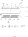
- FIG. 10 is a perspective view illustrating an unfolded state before a positive electrode plate and a negative electrode plate are wound in an electrode assembly according to a fourth embodiment of the present invention.
- an electrode assembly 1100 comprises a positive electrode plate 1110 comprising a positive electrode active material portion 1112 and a positive electrode non-coating portion 1113, a positive electrode tab 1150 disposed on the positive electrode non-coating portion 1113, a negative electrode plate 1120 comprising a negative electrode active material portion 1122 and a negative electrode non-coating portion 1123, a negative electrode tab 1160 disposed on the negative electrode non-coating portion 1123, and a separator 1140 disposed between the positive electrode plate 1110 and the negative electrode plate 1120.
- the electrode assembly 1100 may be a chargeable and dischargeable power generation element and have a structure in which an electrode 1130 and the separator 1140 are combined and alternately stacked.
- the electrode assembly 1100 may be an electrode assembly for a lithium ion secondary battery and may have a wound shape.
- the electrode 1130 comprises the positive electrode plate 1110 and the negative electrode 1120. Also, the separator 1140 separates the positive electrode plate 1110 and the negative electrode plate 1120 from each other so that the positive electrode plate 1110 and the negative electrode plate 1120 are electrically insulated from each other.
- the positive electrode plate 1110 and the negative electrode plate 1120 may be alternately stacked and wound together with the separator 1140 and may be provided in the form of a roll.
- the electrode assembly 1100 may be, for example, wound in a circular or oval shape so as to be formed in a jelly roll type.
- the positive electrode plate 1110 comprises a positive electrode collector 1111, a positive electrode active material portion 1112 that is an area on which a positive electrode active material is stacked on the positive electrode collector 1111, and a positive electrode non-coating portion 1113 that is an area on which the positive electrode active material is not stacked.
- the positive electrode collector 1111 may be provided as foil made of an aluminum (Al) material.
- the positive electrode active material portion 1112 comprises a positive electrode active material stacked on a first surface M12 of the positive electrode collector 1111. Also, the positive electrode active material portion 1112 may further comprise a positive electrode active material stacked on a second surface of the positive electrode collector 1111. Also, the positive electrode active material portion 1112 may further comprise a binder and a conductive material in addition to the positive electrode active material.
- the positive electrode non-coating portion 1113 may be divided into two portions spaced apart from each other and thus comprises a first positive electrode non-coating portion 1113a and a second positive electrode non-coating portion 1113b.
- the first positive electrode non-coating portion 1113a is disposed between both ends of the positive electrode plate 1110.
- the positive electrode non-coating portion 1113 may be divided into three portions spaced apart from each other and thus comprises a first positive electrode non-coating portion 1113a and a second positive electrode non-coating portion 1113b.
- the positive electrode non-coating portion 1113 may comprise a third positive electrode non-coating portion 1113c.
- the first positive electrode non-coating portion 1113a is disposed between both ends of the positive electrode plate 1110.
- the positive electrode tab 1150 is disposed on the positive electrode non-coating portion 1113 of the positive electrode plate 1110. Also, the positive electrode tab 1150 comprises a first positive electrode tab 1151 disposed on the first positive electrode non-coating portion 113a. Here, one end of the first positive electrode tab 1151 may be attached and fixed to the first positive electrode non-coating portion 1113a, and the other end of the first positive electrode tab 1151 may protrude from the positive electrode plate 1110. Furthermore, the positive electrode tab 1150 may further comprise a second positive electrode tab (not shown) disposed on the second positive electrode non-coating portion 1113b.
- the negative electrode plate 1210 comprises a negative electrode collector 1121, a negative electrode active material portion 1122 that is an area on which a negative electrode active material is stacked and a negative electrode non-coating portion 1123 that is an area on which the negative electrode active material is not stacked.
- the negative electrode collector 1121 may be foil made of a copper (Cu) or nickel (Ni) material.
- the negative electrode active material portion 1122 comprises a negative electrode active material stacked on a first surface M21 of the negative electrode collector 1121.
- the first surface M21 of the negative electrode collector is a surface facing the first surface M12 of the positive electrode collector 1111. That is, although the first surface M21 of the negative electrode collector 1122 is illustrated in the same direction as the first surface M12 of the positive electrode collector 1111, for convenience of description in FIG. 6 , the first surface M21 of the negative electrode collector 1121 may be substantially a surface facing the first surface M12 of the positive electrode collector 1111.
- the negative electrode active material portion 1122 may further comprise a negative electrode active material stacked on a second surface of the negative electrode collector 1121.
- the negative electrode active material portion 1122 may further comprise a binder and a conductive material in addition to the negative electrode active material.
- the negative electrode non-coating portion 1123 comprises a first negative electrode non-coating portion 1123a disposed between both ends of the negative electrode plate 1120 and second and third negative electrode non-coating portions 1123b and 1123c disposed at both ends of the negative electrode plate 1120.
- first positive electrode non-coating portion 1113b and the first negative electrode non-coating portion 1123a are disposed corresponding to each other.
- the negative electrode tab 1160 is disposed on the negative electrode non-coating portion 1123.
- one end of the negative electrode tab 1160 may be attached and fixed to the negative electrode non-coating portion 1123, and the other end of the negative electrode tab 1160 may protrude from the negative electrode plate 1120.
- the negative electrode tab 1160 may comprise a first negative electrode tab 1161 provided on the first negative electrode non-coating portion 1123a, a second negative electrode tab 1162 provided on the second negative electrode non-coating portion 1123b, and a third negative electrode tab 1163 disposed on the third negative electrode non-coating portion 1123c.
- the separator 1140 is made of an insulation material and is alternately stacked together with the positive electrode plate 1110 and the negative electrode plate 1120.
- the separator 1140 may be disposed between the positive electrode plate 1110 and the negative electrode plate 1120 and disposed on an outer surface of the positive electrode plate 1110 or the negative electrode plate 1120.
- the first positive electrode tab 1151 and the first negative electrode tab 1161 may be disposed so as not to overlap each other with respect to a direction in which the positive electrode 1110 and the negative electrode 1120 face each other.
- the direction in which the positive electrode 1110 and the negative electrode 1120 face each other may be, for example, a lateral direction of a winding central axis.
- ends of the first positive electrode tab 1151 and the first negative electrode tab 1161 may be spaced a predetermined distance from each other with respect to the direction parallel to the winding central axis so as not to overlap each other.
- a positive electrode insulation tape may be further attached to the positive electrode non-coating portion 1113 to cover the positive electrode tab 1150, and a negative electrode insulation tape may be further attached to the negative electrode non-coating portion 1123 to cover the negative electrode tab 1160.
- the positive electrode insulation tape and the negative electrode insulation tape may be attached in the same manner as that in which the positive electrode insulation tape 170 and the negative electrode insulation tape 180 of the electrode assembly 100 according to the foregoing first embodiment of the present invention are attached.
- the manufactured electrode assembly was accommodated together with an electrolyte in a battery case to manufacture a secondary battery.
- Electricity was applied to the secondary battery to measure an effect of improving resistance.
Landscapes
- Chemical & Material Sciences (AREA)
- Chemical Kinetics & Catalysis (AREA)
- Electrochemistry (AREA)
- General Chemical & Material Sciences (AREA)
- Engineering & Computer Science (AREA)
- Manufacturing & Machinery (AREA)
- Materials Engineering (AREA)
- Secondary Cells (AREA)
- Connection Of Batteries Or Terminals (AREA)
- Cell Separators (AREA)
- Battery Electrode And Active Subsutance (AREA)
Claims (14)
- Elektrodenanordnung, umfassend:eine positive Elektrodenbahn (110), welche einen positive Elektrode-Aktivmaterialabschnitt (112), welcher ein Bereich ist, an welchem ein positive Elektrode-Aktivmaterial an einem positive Elektrode-Kollektor (111) gestapelt ist, und einen positive Elektrode-Nichtbeschichtungsabschnitt (113) umfasst, welcher ein Bereich ist, an welchem das positive Elektrode-Aktivmaterial nicht gestapelt ist;einen positiven Elektrodenstreifen (150), welcher an dem positive Elektrode-Nichtbeschichtungsabschnitt (113) angeordnet ist;eine negative Elektrodenbahn (120), welche einen negative Elektrode-Aktivmaterialabschnitt (122), welcher ein Bereich ist, an welchem ein negative Elektrode-Aktivmaterial an einem negative Elektrode-Kollektor (121) gestapelt ist, und einen negative Elektrode-Nichtbeschichtungsabschnitt (123) umfasst, welcher ein Bereich ist, an welchem das negative Elektrode-Aktivmaterial nicht gestapelt ist;einen negativen Elektrodenstreifen (160), welcher an dem negative Elektrode-Nichtbeschichtungsabschnitt angeordnet ist; undeinen Separator (140), welcher dazu eingerichtet ist, die positive Elektrodenbahn und die negative Elektrodenbahn voneinander zu isolieren,wobei der positive Elektrode-Nichtbeschichtungsabschnitt (113) einen ersten positive Elektrode-Nichtbeschichtungsabschnitt (113a) und einen zweiten positive Elektrode-Nichtbeschichtungsabschnitt (113b) umfasst, welche an zwei Abschnitten, welche voneinander beabstandet sind, an der positiven Elektrodenbahn (110) bereitgestellt sind,wobei der negative Elektrode-Nichtbeschichtungsabschnitt (123) einen ersten negative Elektrode-Nichtbeschichtungsabschnitt (123a), welcher zwischen beiden Seitenabschnitten der negativen Elektrodenbahn (120) angeordnet ist, und einen zweiten sowie einen dritten positive Elektrode-Nichtbeschichtungsabschnitt (123b, 123c) umfasst, welche jeweils an beiden Seitenabschnitten der negativen Elektrodenbahn (120) angeordnet sind, undwobei der erste positive Elektrode-Nichtbeschichtungsabschnitt (113a) und der erste negative Elektrode-Nichtbeschichtungsabschnitt (123a) an Positionen angeordnet sind, welche einander entsprechen,wobei der positive Elektrodenstreifen (150) einen ersten positiven Elektrodenstreifen (151), welcher an dem ersten positive Elektrode-Nichtbeschichtungsabschnitt (113a) angeordnet ist, und einen zweiten positiven Elektrodenstreifen (152) umfasst, welcher an dem zweiten positive Elektrode-Nichtbeschichtungsabschnitt (113b) angeordnet ist, undwobei der negative Elektrodenstreifen (160) einen ersten negativen Elektrodenstreifen (161), welcher an dem ersten negative Elektrode-Nichtbeschichtungsabschnitt (123a) angeordnet ist, einen zweiten negativen Elektrodenstreifen (162), welcher an dem zweiten negative Elektrode-Nichtbeschichtungsabschnitt (123b) angeordnet ist, und einen dritten negativen Elektrodenstreifen (163) umfasst, welcher an dem dritten negative Elektrode-Nichtbeschichtungsabschnitt (123c) angeordnet ist,wobei die Elektrodenanordnung eine Elektrodenanordnung für eine Lithiumionen-Sekundärbatterie umfasst,wobei die positive Elektrodenbahn (110), der Separator (140) und die negative Elektrodenbahn (120) alternierend gestapelt sind, um gewickelt zu sein,wobei ein erstes negative Elektrode-Isolierband (181) ferner an dem ersten negative Elektrode-Nichtbeschichtungsabschnitt (123a) befestigt ist, um den ersten negativen Elektrodenstreifen (161) abzudecken, undwobei ein Lithiumionen-Ablagerungsverhinderungsband (190) ferner an einer Fläche des positive Elektrode-Aktivmaterialabschnitts (112) der positiven Elektrodenbahn (110) befestigt ist, welche dem ersten negative Elektrode-Isolierband (181) zugewandt ist, um zu verhindern, dass Lithiumionen zur Ablagerung angesammelt werden, wenn geladen und entladen wird.
- Elektrodenanordnung nach Anspruch 1, wobei der Separator (140) ein Isoliermaterial umfasst, welches Poren aufweist, durch welche sich die Lithiumionen bewegen, und
wobei jedes aus dem ersten negative Elektrode-Isolierband (181) und dem Lithiumionen-Ablagerungsverhinderungsband (190) ein Isoliermaterial umfasst. - Elektrodenanordnung nach Anspruch 1, wobei, in jeder aus der positiven Elektrodenbahn (110) und der negativen Elektrodenbahn (120), ein Seitenabschnitt von beiden Seitenabschnitten im Uhrzeigersinn gewickelt ist, um an einem äußeren Wickelabschnitt angeordnet zu sein, und der andere Seitenabschnitt an einem zentralen Wickelabschnitt angeordnet ist, und
wobei der erste positive Elektrode-Nichtbeschichtungsabschnitt (113a) und der zweite positive Elektrode-Nichtbeschichtungsabschnitt (113b) zwischen beiden Seitenabschnitten an der positiven Elektrodenbahn (110) angeordnet sind, wobei der erste positive Elektrode-Nichtbeschichtungsabschnitt (113a) an einer Seite von einem Seitenabschnitt der positiven Elektrodenbahn (110) angeordnet ist. - Elektrodenanordnung nach Anspruch 3, wobei eine Fläche beider Flächen von jeder aus der positiven Elektrodenbahn (110) und der negativen Elektrodenbahn (120) während dem Wickeln nach innen angeordnet ist und die andere Fläche von der Wickelseite nach außen angeordnet ist.
- Elektrodenanordnung nach Anspruch 1, wobei jede aus der positiven Elektrodenbahn (110) und der negativen Elektrodenbahn (120) von dem anderen Seitenabschnitt beider Seitenabschnitte davon gewickelt ist, um im Uhrzeigersinn in Richtung eines Seitenabschnitts gewickelt zu sein, wobei der andere Seitenabschnitt an einem zentralen Wickelabschnitt angeordnet ist, und wobei der eine Seitenabschnitt an einem äußeren Wickelabschnitt angeordnet ist, und
wobei jeder aus dem ersten positive Elektrode-Nichtbeschichtungsabschnitt (113a) und dem zweiten positive Elektrode-Nichtbeschichtungsabschnitt (113b) zwischen beiden Seitenabschnitten an der positiven Elektrodenbahn (110) angeordnet ist, wobei der erste positive Elektrode-Nichtbeschichtungsabschnitt (113a) an einer Seite von dem einen Seitenabschnitt der positiven Elektrodenbahn (110) angeordnet ist. - Elektrodenanordnung nach Anspruch 5, wobei eine Fläche beider Flächen von jeder aus der positiven Elektrodenbahn (110) und der negativen Elektrodenbahn (120) während dem Wickeln nach außen angeordnet ist und die andere Fläche von der Wickelseite nach innen angeordnet ist.
- Elektrodenanordnung nach Anspruch 4 oder 6, wobei das Lithiumionen-Ablagerungsverhinderungsband (190) an der anderen Fläche der positiven Elektrodenbahn angeordnet ist,
wobei das Lithiumionen-Ablagerungsverhinderungsband (190) an einer Fläche des positive Elektrode-Aktivmaterialabschnitts (112) angeordnet ist, welche zwischen dem einen Seitenabschnitt der positiven Elektrodenbahn (110) und dem ersten positive Elektrode-Nichtbeschichtungsabschnitt (113a) gestapelt ist, welcher nahe an dem einen Seitenabschnitt der positiven Elektrodenbahn (110) angeordnet ist. - Elektrodenanordnung nach Anspruch 7, wobei der Separator (140) umfasst:einen ersten Separator (141), welcher zwischen einer Fläche der positiven Elektrodenbahn (110) und der anderen Fläche der negativen Elektrodenbahn (120) angeordnet ist; undeinen zweiten Separator (142), welcher an einer Fläche der negativen Elektrodenbahn (120) angeordnet ist,wobei der erste negative Elektrode-Nichtbeschichtungsabschnitt (123a) und das Lithiumionen-Ablagerungsverhinderungsband (190) mit dem zweiten Separator (142) dazwischen einander zugewandt sind.
- Elektrodenanordnung nach einem der Ansprüche 1 bis 6, wobei der erste positive Elektrodenstreifen (151) und der erste negative Elektrodenstreifen (161) derart angeordnet sind, dass sie sich in Bezug auf eine Richtung nicht überlappen, in welcher die positive Elektrodenbahn (110) und die negative Elektrodenbahn (120) einander zugewandt sind.
- Elektrodenanordnung nach Anspruch 9, wobei der erste positive Elektrodenstreifen (151) in Richtung einer Seite in Bezug auf eine Richtung hervorsteht, welche parallel zu einer zentralen Wickelachse (C) ist,wobei der erste negative Elektrodenstreifen (161) in Richtung der anderen Seite in Bezug auf die Richtung hervorsteht, welche parallel zu der zentralen Wickelachse (C) ist, undwobei Enden des ersten positiven Elektrodenstreifens (151) und des ersten negativen Elektrodenstreifens (161) derart angeordnet sind, dass sie in Bezug auf die Richtung, welche parallel zu der zentralen Wickelachse (C) ist, um einen vorbestimmten Abstand voneinander beabstandet sind, um sich einander nicht zu überlappen.
- Elektrodenanordnung, umfassend:eine positive Elektrodenbahn (110), welche einen positive Elektrode-Aktivmaterialabschnitt (112), welcher ein Bereich ist, an welchem ein positive Elektrode-Aktivmaterial an einem positive Elektrode-Kollektor (111) gestapelt ist, und einen positive Elektrode-Nichtbeschichtungsabschnitt (113) umfasst, welcher ein Bereich ist, an welchem das positive Elektrode-Aktivmaterial nicht gestapelt ist;einen positiven Elektrodenstreifen (150), welcher an dem positive Elektrode-Nichtbeschichtungsabschnitt (113) angeordnet ist;eine negative Elektrodenbahn (120), welche einen negative Elektrode-Aktivmaterialabschnitt (122), welcher ein Bereich ist, an welchem ein negative Elektrode-Aktivmaterial an einem negative Elektrode-Kollektor (121) gestapelt ist, und einen negative Elektrode-Nichtbeschichtungsabschnitt (123) umfasst, welcher ein Bereich ist, an welchem das negative Elektrode-Aktivmaterial nicht gestapelt ist;einen negativen Elektrodenstreifen (160), welcher an dem negative Elektrode-Nichtbeschichtungsabschnitt (123) angeordnet ist; undeinen Separator (140), welcher dazu eingerichtet ist, die positive Elektrodenbahn (110) und die negative Elektrodenbahn (120) voneinander zu isolieren,wobei der positive Elektrode-Nichtbeschichtungsabschnitt (113) einen ersten positive Elektrode-Nichtbeschichtungsabschnitt (113a) und einen zweiten positive Elektrode-Nichtbeschichtungsabschnitt (113b) umfasst, welche an zwei Abschnitten, welche voneinander beabstandet sind, an der positiven Elektrodenbahn (110) bereitgestellt sind,wobei der negative Elektrode-Nichtbeschichtungsabschnitt (123) einen ersten negative Elektrode-Nichtbeschichtungsabschnitt (123a), welcher zwischen beiden Seitenabschnitten der negativen Elektrodenbahn (110) angeordnet ist, und einen zweiten sowie einen dritten negative Elektrode-Nichtbeschichtungsabschnitt (123b, 123c) umfasst, welche jeweils an beiden Seitenabschnitten der negativen Elektrodenbahn (120) angeordnet sind, undwobei der zweite positive Elektrode-Nichtbeschichtungsabschnitt (113b) und der erste negative Elektrode-Nichtbeschichtungsabschnitt (123a) an Positionen angeordnet sind, welche einander entsprechen,wobei der positive Elektrodenstreifen (150) einen ersten positiven Elektrodenstreifen (151), welcher an dem ersten positive Elektrode-Nichtbeschichtungsabschnitt (113a) angeordnet ist, und einen zweiten positiven Elektrodenstreifen (152) umfasst, welcher an dem zweiten positive Elektrode-Nichtbeschichtungsabschnitt (113b) angeordnet ist, undwobei der negative Elektrodenstreifen (160) einen ersten negativen Elektrodenstreifen (161), welcher an dem ersten negative Elektrode-Nichtbeschichtungsabschnitt (123a) angeordnet ist, einen zweiten negativen Elektrodenstreifen (162), welcher an dem zweiten negative Elektrode-Nichtbeschichtungsabschnitt (123b) angeordnet ist, und einen dritten negativen Elektrodenstreifen (163) umfasst, welcher an dem dritten negative Elektrode-Nichtbeschichtungsabschnitt (123c) angeordnet ist,wobei die Elektrodenanordnung eine Elektrodenanordnung für eine Lithiumionen-Sekundärbatterie umfasst,wobei die positive Elektrodenbahn (110), der Separator (140) und die negative Elektrodenbahn (120) alternierend gestapelt sind, um gewickelt zu sein,wobei ein erstes negative Elektrode-Isolierband (181) ferner an dem ersten negative Elektrode-Nichtbeschichtungsabschnitt (123a) befestigt ist, um den ersten negativen Elektrodenstreifen (161) abzudecken, undwobei ein Lithiumionen-Ablagerungsverhinderungsband (190) ferner an einer Fläche des positive Elektrode-Aktivmaterialabschnitts (112) der positiven Elektrodenbahn (110) befestigt ist, welche dem ersten negative Elektrode-Isolierband (181) zugewandt ist, um zu verhindern, dass Lithiumionen zur Ablagerung angesammelt werden, wenn geladen und entladen wird.
- Elektrodenanordnung nach Anspruch 11, wobei, in jeder aus der positiven Elektrodenbahn (110) und der negativen Elektrodenbahn (120), ein Seitenabschnitt von beiden Seitenabschnitten im Uhrzeigersinn gewickelt ist, um an einem äußeren Wickelabschnitt angeordnet zu sein, und der andere Seitenabschnitt an einem zentralen Wickelabschnitt angeordnet ist, und
wobei der erste positive Elektrode-Nichtbeschichtungsabschnitt (113a) und der zweite positive Elektrode-Nichtbeschichtungsabschnitt (113b) zwischen beiden Seitenabschnitten an der positiven Elektrodenbahn (110) angeordnet sind, wobei der zweite positive Elektrode-Nichtbeschichtungsabschnitt (113b) an einer Seite des anderen Seitenabschnitts der positiven Elektrodenbahn (110) angeordnet ist. - Sekundärbatterie, umfassend die Elektrodenanordnung nach Anspruch 1 und ein Batteriegehäuse, welches dazu eingerichtet ist, die Elektrodenanordnung aufzunehmen.
- Elektrodenanordnung, umfassend:eine positive Elektrodenplatte (1110), welche einen positive Elektrode-Aktivmaterialabschnitt (1112), auf welchen an einer ersten Fläche eines positive Elektrode-Kollektors (1111) ein positive Elektrode-Aktivmaterial aufgebracht ist, und einen ersten positive Elektrode-Nichtbeschichtungsabschnitt (1113a) umfasst, welcher ein Bereich ist, an welchem das positive Elektrode-Aktivmaterial nicht aufgebracht ist;einen positiven Elektrodenstreifen (1150), welcher an dem ersten positive Elektrode-Nichtbeschichtungsabschnitt befestigt ist und welcher einen ersten positiven Elektrodenstreifen und einen zweiten positiven Elektrodenstreifen umfasst;eine negative Elektrodenplatte (1120), welche einen negative Elektrode-Aktivmaterialabschnitt (1122), auf welchen an einer ersten Fläche eines negative Elektrode-Kollektors (1121), welche der ersten Fläche des positive Elektrode-Kollektors (1111) zugewandt ist, ein negative Elektrode-Aktivmaterial aufgebracht ist, und einen ersten negative Elektrode-Nichtbeschichtungsabschnitt (1123a) umfasst, welcher ein Bereich ist, an welchem das negative Elektrode-Aktivmaterial nicht aufgebracht ist,einen Separator (1140), welcher zwischen der positiven Elektrodenplatte und der negativen Elektrodenplatte angeordnet ist,wobei der erste positive Elektrode-Nichtbeschichtungsabschnitt (1113a) zwischen einem Ende und dem anderen Ende der positiven Elektrodenplatte in einer longitudinalen Richtung der positiven Elektrodenplatte angeordnet ist, undwobei der erste negative Elektrode-Nichtbeschichtungsabschnitt an einer Position angeordnet ist, welche den ersten positive Elektrode-Nichtbeschichtungsabschnitt überlappt,wobei der erste negative Elektrode-Nichtbeschichtungsabschnitt (1123a) zwischen einem zweiten negative Elektrode-Nichtbeschichtungsabschnitt und einem dritten negative Elektrode-Nichtbeschichtungsabschnitt angeordnet ist, welche jeweils an jedem von beiden Seitenabschnitten der negativen Elektrodenplatte angeordnet sind, undwobei die Elektrodenanordnung ferner einen negativen Elektrodenstreifen umfasst, welcher an dem ersten negative Elektrode-Nichtbeschichtungsabschnitt angeordnet ist und welcher einen ersten negativen Elektrodenstreifen, einen zweiten negativen Elektrodenstreifen und einen dritten negativen Elektrodenstreifen umfasst,wobei die positive Elektrodenplatte ferner einen zweiten positive Elektrode-Nichtbeschichtungsabschnitt (1113b) umfasst, welcher ein Bereich ist, auf welchen das positive Elektrode-Aktivmaterial nicht aufgebracht ist, wobei der zweite positive Elektrodenstreifen ferner an dem zweiten positive Elektrode-Nichtbeschichtungsabschnitt befestigt ist, undwobei die negative Elektrodenplatte ferner einen zweiten und einen dritten negativen Elektrode-Nichtbeschichtungsabschnitt (1123b, 1123c) umfasst, welche Bereiche sind, auf welchen das negative Elektrode-Aktivmaterial nicht aufgebracht ist, wobei der zweite und der dritte negative Elektrodenstreifen ferner an dem zweiten negativen Elektrode-Nichtbeschichtungsabschnitt bzw. dem zweiten negativen Elektrode-Nichtbeschichtungsabschnitt befestigt sind,wobei die Elektrodenanordnung eine Elektrodenanordnung für eine Lithiumionen-Sekundärbatterie umfasst,wobei die positive Elektrodenplatte (1110), der Separator (1140) und die negative Elektrodenplatte (1120) alternierend gestapelt sind, um gewickelt zu sein,wobei ein erstes negative Elektrode-Isolierband ferner an dem ersten negative Elektrode-Nichtbeschichtungsabschnitt befestigt ist, um den ersten negativen Elektrodenstreifen abzudecken, welcher an dem ersten negative Elektrode-Nichtbeschichtungsabschnitt (1123a) befestigt ist, undwobei ein Lithiumionen-Ablagerungsverhinderungsband ferner an einem Abschnitt der positiven Elektrodenplatte befestigt ist, welcher dem ersten negative Elektrode-Isolierband zugewandt ist, um zu verhindern, dass Lithiumionen zur Ablagerung angesammelt werden, wenn geladen und entladen wird, undwobei der erste negative Elektrode-Nichtbeschichtungsabschnitt und das Lithiumionen-Ablagerungsverhinderungsband mit dem Separator dazwischen einander zugewandt sind, undwobei das Lithiumionen-Ablagerungsverhinderungsband an einer Fläche eines positive Elektrode-Aktivmaterialabschnitts der positiven Elektrodenplatte angeordnet ist.
Applications Claiming Priority (3)
| Application Number | Priority Date | Filing Date | Title |
|---|---|---|---|
| KR20180084529 | 2018-07-20 | ||
| KR1020190066144A KR102097107B1 (ko) | 2018-07-20 | 2019-06-04 | 전극 조립체 및 이를 포함하는 이차전지 |
| PCT/KR2019/008948 WO2020017923A1 (ko) | 2018-07-20 | 2019-07-19 | 전극 조립체 및 이를 포함하는 이차전지 |
Publications (3)
| Publication Number | Publication Date |
|---|---|
| EP3817123A1 EP3817123A1 (de) | 2021-05-05 |
| EP3817123A4 EP3817123A4 (de) | 2022-04-27 |
| EP3817123B1 true EP3817123B1 (de) | 2025-07-02 |
Family
ID=69165161
Family Applications (1)
| Application Number | Title | Priority Date | Filing Date |
|---|---|---|---|
| EP19837600.6A Active EP3817123B1 (de) | 2018-07-20 | 2019-07-19 | Elektrodenanordnung und wiederaufladbare batterie damit |
Country Status (6)
| Country | Link |
|---|---|
| EP (1) | EP3817123B1 (de) |
| JP (1) | JP7616739B2 (de) |
| ES (1) | ES3036035T3 (de) |
| HU (1) | HUE072602T2 (de) |
| PL (1) | PL3817123T3 (de) |
| WO (1) | WO2020017923A1 (de) |
Families Citing this family (11)
| Publication number | Priority date | Publication date | Assignee | Title |
|---|---|---|---|---|
| KR20210022454A (ko) * | 2019-08-20 | 2021-03-03 | 삼성에스디아이 주식회사 | 전극 조립체 및 이를 포함하는 이차 전지 |
| WO2021198857A1 (en) * | 2020-03-31 | 2021-10-07 | Tvs Motor Company Limited | Coin-type lithium-ion cells |
| JP7396481B2 (ja) | 2020-06-09 | 2023-12-12 | 株式会社村田製作所 | 二次電池、電子機器及び電動工具 |
| EP3982441A1 (de) * | 2020-10-12 | 2022-04-13 | E-one Moli Energy Corp. | Elektrodenkörper und zylindrische lithiumbatterie damit |
| KR102831589B1 (ko) * | 2020-12-24 | 2025-07-09 | 주식회사 엘지에너지솔루션 | 전극 조립체 및 이를 포함하는 이차전지 |
| CN112820950B (zh) * | 2021-03-12 | 2025-12-23 | 横店集团东磁股份有限公司 | 一种圆柱形锂离子电池及其制造方法 |
| WO2022188400A1 (zh) * | 2021-03-12 | 2022-09-15 | 横店集团东磁股份有限公司 | 一种圆柱形锂离子电池及其制造方法 |
| KR102901452B1 (ko) * | 2021-08-19 | 2025-12-18 | 주식회사 엘지에너지솔루션 | 단락 방지용 코팅부가 구비된 전극조립체 |
| JP7402206B2 (ja) | 2021-08-24 | 2023-12-20 | プライムプラネットエナジー&ソリューションズ株式会社 | 電池 |
| CN219759680U (zh) * | 2022-12-05 | 2023-09-26 | 珠海冠宇电池股份有限公司 | 一种电极组件和电池 |
| WO2025028176A1 (ja) * | 2023-07-31 | 2025-02-06 | パナソニックIpマネジメント株式会社 | 非水電解質二次電池 |
Family Cites Families (20)
| Publication number | Priority date | Publication date | Assignee | Title |
|---|---|---|---|---|
| JP3428448B2 (ja) * | 1998-08-21 | 2003-07-22 | 三菱電機株式会社 | 電極構造体およびそれを用いた電池 |
| KR100490548B1 (ko) * | 2002-12-27 | 2005-05-17 | 삼성에스디아이 주식회사 | 권취형 전극 조립체를 구비한 이차 전지 |
| KR100509606B1 (ko) * | 2003-02-19 | 2005-08-22 | 삼성에스디아이 주식회사 | 젤리-롤형의 전지부와, 이의 와인딩 방법 및 이를이용하여 제조된 리튬 이차 전지 |
| JP2006260892A (ja) * | 2005-03-16 | 2006-09-28 | Dainippon Printing Co Ltd | 非水電解液二次電池用電極板、その製造方法、及び非水電解液二次電池 |
| CN1929186A (zh) * | 2005-09-09 | 2007-03-14 | 东莞新能源电子科技有限公司 | 一种卷绕式二次锂离子电池的卷绕方法 |
| KR101009517B1 (ko) * | 2008-06-23 | 2011-01-18 | 삼성에스디아이 주식회사 | 전극 조립체와 이를 이용한 리튬 이차 전지 |
| CN102484240A (zh) * | 2009-01-28 | 2012-05-30 | K2能源解决方案公司 | 电池极耳结构 |
| WO2012026705A2 (ko) * | 2010-08-23 | 2012-03-01 | 주식회사 엘지화학 | 개선된 구조의 젤리-롤 및 이를 포함하는 이차전지 |
| KR101254890B1 (ko) * | 2011-01-31 | 2013-04-15 | 삼성에스디아이 주식회사 | 전극 조립체 및 이를 구비하는 이차 전지 |
| KR101199161B1 (ko) | 2011-02-11 | 2012-11-12 | 삼성에스디아이 주식회사 | 전극 조립체 및 이를 이용한 이차 전지 |
| JP2015035250A (ja) | 2011-11-30 | 2015-02-19 | 三洋電機株式会社 | 非水電解質二次電池 |
| KR101439834B1 (ko) * | 2012-11-08 | 2014-09-17 | 주식회사 엘지화학 | 플렉서블 젤리롤 타입 2차 전지 |
| KR101678537B1 (ko) * | 2013-07-31 | 2016-11-22 | 삼성에스디아이 주식회사 | 이차 전지 |
| KR101637071B1 (ko) * | 2014-01-28 | 2016-07-06 | 주식회사 엘지화학 | 부분 절곡 기능을 갖는 전극 조립체 및 이를 포함하는 배터리 셀 |
| KR102262668B1 (ko) | 2014-01-28 | 2021-06-09 | 리튬 웍스 테크놀로지 비.브이. | 원주형 전기화학 셀 및 제조 방법 |
| KR102234292B1 (ko) * | 2014-04-09 | 2021-03-31 | 삼성에스디아이 주식회사 | 전극 조립체 및 이를 구비한 이차 전지 |
| KR20160010080A (ko) * | 2014-07-18 | 2016-01-27 | 주식회사 엘지화학 | 위치 가변적 전극 탭-리드- 결합부로 이루어진 전극조립체 및 이를 포함하고 있는 전지셀 |
| KR101781826B1 (ko) * | 2015-02-17 | 2017-09-26 | 주식회사 엘지화학 | 복수의 양극 탭들과 음극 탭들을 포함하는 원통형 이차전지 |
| KR20160108857A (ko) * | 2015-03-09 | 2016-09-21 | 주식회사 엘지화학 | 복수의 양극 탭들과 음극 탭들을 포함하는 원통형 이차전지 |
| EP3236513A1 (de) * | 2016-04-22 | 2017-10-25 | HILTI Aktiengesellschaft | Elektrodenanordnung für eine batteriezelle |
-
2019
- 2019-07-19 HU HUE19837600A patent/HUE072602T2/hu unknown
- 2019-07-19 PL PL19837600.6T patent/PL3817123T3/pl unknown
- 2019-07-19 ES ES19837600T patent/ES3036035T3/es active Active
- 2019-07-19 EP EP19837600.6A patent/EP3817123B1/de active Active
- 2019-07-19 WO PCT/KR2019/008948 patent/WO2020017923A1/ko not_active Ceased
-
2023
- 2023-04-06 JP JP2023061929A patent/JP7616739B2/ja active Active
Also Published As
| Publication number | Publication date |
|---|---|
| JP2023085480A (ja) | 2023-06-20 |
| WO2020017923A1 (ko) | 2020-01-23 |
| PL3817123T3 (pl) | 2025-09-01 |
| JP7616739B2 (ja) | 2025-01-17 |
| ES3036035T3 (en) | 2025-09-12 |
| EP3817123A1 (de) | 2021-05-05 |
| EP3817123A4 (de) | 2022-04-27 |
| HUE072602T2 (hu) | 2025-11-28 |
Similar Documents
| Publication | Publication Date | Title |
|---|---|---|
| US12199314B2 (en) | Electrode assembly and secondary battery comprising the same | |
| EP3817123B1 (de) | Elektrodenanordnung und wiederaufladbare batterie damit | |
| JP7206562B2 (ja) | 二次電池 | |
| US20240055741A1 (en) | Electrode assembly and secondary battery comprising the same | |
| US20240313266A1 (en) | Secondary Battery | |
| US12009512B2 (en) | Nonaqueous electrolyte secondary battery | |
| JP2023530349A (ja) | 高い比エネルギー密度を有するリチウムイオン電池 | |
| EP4037068A1 (de) | Elektrodenanordnung und sekundärbatterie damit | |
| US20230231262A1 (en) | Secondary Battery | |
| EP4164028B1 (de) | Elektrodenanordnung und sekundärbatterie damit | |
| JP7520561B2 (ja) | 蓄電素子 | |
| KR20240030811A (ko) | 전극 조립체 및 이를 포함하는 이차 전지 | |
| EP4579867A1 (de) | Elektrodenanordnung und sekundärbatterie damit | |
| KR20250068295A (ko) | 전극 조립체 및 이를 포함하는 이차전지 | |
| JP2025500602A (ja) | ゼリーロール型電極組立体、これを含む電池セル、および円筒型電池 | |
| KR20250020158A (ko) | 전극 조립체, 이차 전지, 배터리팩 및 이동 수단 | |
| KR20260059534A (ko) | 젤리롤형 전극 조립체, 이를 포함하는 전지셀, 및 원통형 전지 | |
| KR20240006681A (ko) | 에너지 저장 소자, 에너지 저장 소자의 조립체 및 제조 방법 | |
| CN117501493A (zh) | 蓄能器元件,由蓄能器元件组成的复合体以及制造方法 |
Legal Events
| Date | Code | Title | Description |
|---|---|---|---|
| STAA | Information on the status of an ep patent application or granted ep patent |
Free format text: STATUS: THE INTERNATIONAL PUBLICATION HAS BEEN MADE |
|
| PUAI | Public reference made under article 153(3) epc to a published international application that has entered the european phase |
Free format text: ORIGINAL CODE: 0009012 |
|
| STAA | Information on the status of an ep patent application or granted ep patent |
Free format text: STATUS: REQUEST FOR EXAMINATION WAS MADE |
|
| 17P | Request for examination filed |
Effective date: 20210130 |
|
| AK | Designated contracting states |
Kind code of ref document: A1 Designated state(s): AL AT BE BG CH CY CZ DE DK EE ES FI FR GB GR HR HU IE IS IT LI LT LU LV MC MK MT NL NO PL PT RO RS SE SI SK SM TR |
|
| DAV | Request for validation of the european patent (deleted) | ||
| DAX | Request for extension of the european patent (deleted) | ||
| RIC1 | Information provided on ipc code assigned before grant |
Ipc: H01M 10/0525 20100101ALI20211104BHEP Ipc: H01M 10/04 20060101ALI20211104BHEP Ipc: H01M 10/0587 20100101AFI20211104BHEP |
|
| RAP1 | Party data changed (applicant data changed or rights of an application transferred) |
Owner name: LG ENERGY SOLUTION LTD. |
|
| RAP3 | Party data changed (applicant data changed or rights of an application transferred) |
Owner name: LG ENERGY SOLUTION, LTD. |
|
| A4 | Supplementary search report drawn up and despatched |
Effective date: 20220325 |
|
| RIC1 | Information provided on ipc code assigned before grant |
Ipc: H01M 10/0525 20100101ALI20220321BHEP Ipc: H01M 10/04 20060101ALI20220321BHEP Ipc: H01M 10/0587 20100101AFI20220321BHEP |
|
| STAA | Information on the status of an ep patent application or granted ep patent |
Free format text: STATUS: EXAMINATION IS IN PROGRESS |
|
| 17Q | First examination report despatched |
Effective date: 20231010 |
|
| GRAP | Despatch of communication of intention to grant a patent |
Free format text: ORIGINAL CODE: EPIDOSNIGR1 |
|
| STAA | Information on the status of an ep patent application or granted ep patent |
Free format text: STATUS: GRANT OF PATENT IS INTENDED |
|
| INTG | Intention to grant announced |
Effective date: 20250226 |
|
| GRAS | Grant fee paid |
Free format text: ORIGINAL CODE: EPIDOSNIGR3 |
|
| P01 | Opt-out of the competence of the unified patent court (upc) registered |
Free format text: CASE NUMBER: APP_13946/2025 Effective date: 20250321 |
|
| GRAA | (expected) grant |
Free format text: ORIGINAL CODE: 0009210 |
|
| STAA | Information on the status of an ep patent application or granted ep patent |
Free format text: STATUS: THE PATENT HAS BEEN GRANTED |
|
| AK | Designated contracting states |
Kind code of ref document: B1 Designated state(s): AL AT BE BG CH CY CZ DE DK EE ES FI FR GB GR HR HU IE IS IT LI LT LU LV MC MK MT NL NO PL PT RO RS SE SI SK SM TR |
|
| REG | Reference to a national code |
Ref country code: GB Ref legal event code: FG4D |
|
| REG | Reference to a national code |
Ref country code: CH Ref legal event code: EP |
|
| REG | Reference to a national code |
Ref country code: DE Ref legal event code: R096 Ref document number: 602019072057 Country of ref document: DE |
|
| REG | Reference to a national code |
Ref country code: IE Ref legal event code: FG4D |
|
| REG | Reference to a national code |
Ref country code: SE Ref legal event code: TRGR |
|
| PGFP | Annual fee paid to national office [announced via postgrant information from national office to epo] |
Ref country code: NL Payment date: 20250708 Year of fee payment: 7 |
|
| REG | Reference to a national code |
Ref country code: ES Ref legal event code: FG2A Ref document number: 3036035 Country of ref document: ES Kind code of ref document: T3 Effective date: 20250912 |
|
| PGFP | Annual fee paid to national office [announced via postgrant information from national office to epo] |
Ref country code: ES Payment date: 20250822 Year of fee payment: 7 |
|
| PGFP | Annual fee paid to national office [announced via postgrant information from national office to epo] |
Ref country code: DE Payment date: 20250707 Year of fee payment: 7 |
|
| PGFP | Annual fee paid to national office [announced via postgrant information from national office to epo] |
Ref country code: TR Payment date: 20250718 Year of fee payment: 7 Ref country code: PL Payment date: 20250709 Year of fee payment: 7 Ref country code: IT Payment date: 20250722 Year of fee payment: 7 |
|
| PGFP | Annual fee paid to national office [announced via postgrant information from national office to epo] |
Ref country code: HU Payment date: 20250929 Year of fee payment: 7 Ref country code: BE Payment date: 20250708 Year of fee payment: 7 Ref country code: GB Payment date: 20250707 Year of fee payment: 7 |
|
| PGFP | Annual fee paid to national office [announced via postgrant information from national office to epo] |
Ref country code: FR Payment date: 20250715 Year of fee payment: 7 |
|
| PGFP | Annual fee paid to national office [announced via postgrant information from national office to epo] |
Ref country code: SE Payment date: 20250708 Year of fee payment: 7 |
|
| REG | Reference to a national code |
Ref country code: NL Ref legal event code: FP |
|
| REG | Reference to a national code |
Ref country code: HU Ref legal event code: AG4A Ref document number: E072602 Country of ref document: HU |
|
| PG25 | Lapsed in a contracting state [announced via postgrant information from national office to epo] |
Ref country code: PT Free format text: LAPSE BECAUSE OF FAILURE TO SUBMIT A TRANSLATION OF THE DESCRIPTION OR TO PAY THE FEE WITHIN THE PRESCRIBED TIME-LIMIT Effective date: 20251103 |
|
| REG | Reference to a national code |
Ref country code: AT Ref legal event code: MK05 Ref document number: 1810316 Country of ref document: AT Kind code of ref document: T Effective date: 20250702 |
|
| PG25 | Lapsed in a contracting state [announced via postgrant information from national office to epo] |
Ref country code: IS Free format text: LAPSE BECAUSE OF FAILURE TO SUBMIT A TRANSLATION OF THE DESCRIPTION OR TO PAY THE FEE WITHIN THE PRESCRIBED TIME-LIMIT Effective date: 20251102 |
|
| PG25 | Lapsed in a contracting state [announced via postgrant information from national office to epo] |
Ref country code: NO Free format text: LAPSE BECAUSE OF FAILURE TO SUBMIT A TRANSLATION OF THE DESCRIPTION OR TO PAY THE FEE WITHIN THE PRESCRIBED TIME-LIMIT Effective date: 20251002 |
|
| REG | Reference to a national code |
Ref country code: LT Ref legal event code: MG9D |
|
| PG25 | Lapsed in a contracting state [announced via postgrant information from national office to epo] |
Ref country code: AT Free format text: LAPSE BECAUSE OF FAILURE TO SUBMIT A TRANSLATION OF THE DESCRIPTION OR TO PAY THE FEE WITHIN THE PRESCRIBED TIME-LIMIT Effective date: 20250702 |
|
| PG25 | Lapsed in a contracting state [announced via postgrant information from national office to epo] |
Ref country code: FI Free format text: LAPSE BECAUSE OF FAILURE TO SUBMIT A TRANSLATION OF THE DESCRIPTION OR TO PAY THE FEE WITHIN THE PRESCRIBED TIME-LIMIT Effective date: 20250702 |
|
| PG25 | Lapsed in a contracting state [announced via postgrant information from national office to epo] |
Ref country code: HR Free format text: LAPSE BECAUSE OF FAILURE TO SUBMIT A TRANSLATION OF THE DESCRIPTION OR TO PAY THE FEE WITHIN THE PRESCRIBED TIME-LIMIT Effective date: 20250702 |
|
| PG25 | Lapsed in a contracting state [announced via postgrant information from national office to epo] |
Ref country code: GR Free format text: LAPSE BECAUSE OF FAILURE TO SUBMIT A TRANSLATION OF THE DESCRIPTION OR TO PAY THE FEE WITHIN THE PRESCRIBED TIME-LIMIT Effective date: 20251003 |
|
| PG25 | Lapsed in a contracting state [announced via postgrant information from national office to epo] |
Ref country code: CZ Free format text: LAPSE BECAUSE OF FAILURE TO SUBMIT A TRANSLATION OF THE DESCRIPTION OR TO PAY THE FEE WITHIN THE PRESCRIBED TIME-LIMIT Effective date: 20250702 |
|
| PG25 | Lapsed in a contracting state [announced via postgrant information from national office to epo] |
Ref country code: LV Free format text: LAPSE BECAUSE OF FAILURE TO SUBMIT A TRANSLATION OF THE DESCRIPTION OR TO PAY THE FEE WITHIN THE PRESCRIBED TIME-LIMIT Effective date: 20250702 |
|
| PG25 | Lapsed in a contracting state [announced via postgrant information from national office to epo] |
Ref country code: BG Free format text: LAPSE BECAUSE OF FAILURE TO SUBMIT A TRANSLATION OF THE DESCRIPTION OR TO PAY THE FEE WITHIN THE PRESCRIBED TIME-LIMIT Effective date: 20250702 |
|
| PG25 | Lapsed in a contracting state [announced via postgrant information from national office to epo] |
Ref country code: RS Free format text: LAPSE BECAUSE OF FAILURE TO SUBMIT A TRANSLATION OF THE DESCRIPTION OR TO PAY THE FEE WITHIN THE PRESCRIBED TIME-LIMIT Effective date: 20251002 |
|
| REG | Reference to a national code |
Ref country code: CH Ref legal event code: H13 Free format text: ST27 STATUS EVENT CODE: U-0-0-H10-H13 (AS PROVIDED BY THE NATIONAL OFFICE) Effective date: 20260224 |
|
| PG25 | Lapsed in a contracting state [announced via postgrant information from national office to epo] |
Ref country code: RO Free format text: LAPSE BECAUSE OF FAILURE TO SUBMIT A TRANSLATION OF THE DESCRIPTION OR TO PAY THE FEE WITHIN THE PRESCRIBED TIME-LIMIT Effective date: 20250702 Ref country code: LU Free format text: LAPSE BECAUSE OF NON-PAYMENT OF DUE FEES Effective date: 20250719 |
|
| PG25 | Lapsed in a contracting state [announced via postgrant information from national office to epo] |
Ref country code: SM Free format text: LAPSE BECAUSE OF FAILURE TO SUBMIT A TRANSLATION OF THE DESCRIPTION OR TO PAY THE FEE WITHIN THE PRESCRIBED TIME-LIMIT Effective date: 20250702 |
|
| PG25 | Lapsed in a contracting state [announced via postgrant information from national office to epo] |
Ref country code: DK Free format text: LAPSE BECAUSE OF FAILURE TO SUBMIT A TRANSLATION OF THE DESCRIPTION OR TO PAY THE FEE WITHIN THE PRESCRIBED TIME-LIMIT Effective date: 20250702 |
|
| PG25 | Lapsed in a contracting state [announced via postgrant information from national office to epo] |
Ref country code: CH Free format text: LAPSE BECAUSE OF NON-PAYMENT OF DUE FEES Effective date: 20250731 |
|
| PG25 | Lapsed in a contracting state [announced via postgrant information from national office to epo] |
Ref country code: SK Free format text: LAPSE BECAUSE OF FAILURE TO SUBMIT A TRANSLATION OF THE DESCRIPTION OR TO PAY THE FEE WITHIN THE PRESCRIBED TIME-LIMIT Effective date: 20250702 Ref country code: EE Free format text: LAPSE BECAUSE OF FAILURE TO SUBMIT A TRANSLATION OF THE DESCRIPTION OR TO PAY THE FEE WITHIN THE PRESCRIBED TIME-LIMIT Effective date: 20250702 |