EP3817151B1 - Orientation de localisation de câblage par rapport à un connecteur électrique - Google Patents
Orientation de localisation de câblage par rapport à un connecteur électrique Download PDFInfo
- Publication number
- EP3817151B1 EP3817151B1 EP20203773.5A EP20203773A EP3817151B1 EP 3817151 B1 EP3817151 B1 EP 3817151B1 EP 20203773 A EP20203773 A EP 20203773A EP 3817151 B1 EP3817151 B1 EP 3817151B1
- Authority
- EP
- European Patent Office
- Prior art keywords
- housing
- insulation
- locating feature
- stripped
- wires
- Prior art date
- Legal status (The legal status is an assumption and is not a legal conclusion. Google has not performed a legal analysis and makes no representation as to the accuracy of the status listed.)
- Active
Links
Images

Classifications
-
- H—ELECTRICITY
- H01—ELECTRIC ELEMENTS
- H01R—ELECTRICALLY-CONDUCTIVE CONNECTIONS; STRUCTURAL ASSOCIATIONS OF A PLURALITY OF MUTUALLY-INSULATED ELECTRICAL CONNECTING ELEMENTS; COUPLING DEVICES; CURRENT COLLECTORS
- H01R12/00—Structural associations of a plurality of mutually-insulated electrical connecting elements, specially adapted for printed circuits, e.g. printed circuit boards [PCB], flat or ribbon cables, or like generally planar structures, e.g. terminal strips, terminal blocks; Coupling devices specially adapted for printed circuits, flat or ribbon cables, or like generally planar structures; Terminals specially adapted for contact with, or insertion into, printed circuits, flat or ribbon cables, or like generally planar structures
- H01R12/70—Coupling devices
- H01R12/77—Coupling devices for flexible printed circuits, flat or ribbon cables or like structures
- H01R12/771—Details
- H01R12/774—Retainers
-
- H—ELECTRICITY
- H01—ELECTRIC ELEMENTS
- H01R—ELECTRICALLY-CONDUCTIVE CONNECTIONS; STRUCTURAL ASSOCIATIONS OF A PLURALITY OF MUTUALLY-INSULATED ELECTRICAL CONNECTING ELEMENTS; COUPLING DEVICES; CURRENT COLLECTORS
- H01R12/00—Structural associations of a plurality of mutually-insulated electrical connecting elements, specially adapted for printed circuits, e.g. printed circuit boards [PCB], flat or ribbon cables, or like generally planar structures, e.g. terminal strips, terminal blocks; Coupling devices specially adapted for printed circuits, flat or ribbon cables, or like generally planar structures; Terminals specially adapted for contact with, or insertion into, printed circuits, flat or ribbon cables, or like generally planar structures
- H01R12/70—Coupling devices
- H01R12/77—Coupling devices for flexible printed circuits, flat or ribbon cables or like structures
- H01R12/771—Details
-
- H—ELECTRICITY
- H01—ELECTRIC ELEMENTS
- H01R—ELECTRICALLY-CONDUCTIVE CONNECTIONS; STRUCTURAL ASSOCIATIONS OF A PLURALITY OF MUTUALLY-INSULATED ELECTRICAL CONNECTING ELEMENTS; COUPLING DEVICES; CURRENT COLLECTORS
- H01R12/00—Structural associations of a plurality of mutually-insulated electrical connecting elements, specially adapted for printed circuits, e.g. printed circuit boards [PCB], flat or ribbon cables, or like generally planar structures, e.g. terminal strips, terminal blocks; Coupling devices specially adapted for printed circuits, flat or ribbon cables, or like generally planar structures; Terminals specially adapted for contact with, or insertion into, printed circuits, flat or ribbon cables, or like generally planar structures
- H01R12/50—Fixed connections
- H01R12/59—Fixed connections for flexible printed circuits, flat or ribbon cables or like structures
- H01R12/592—Fixed connections for flexible printed circuits, flat or ribbon cables or like structures connections to contact elements
-
- H—ELECTRICITY
- H01—ELECTRIC ELEMENTS
- H01R—ELECTRICALLY-CONDUCTIVE CONNECTIONS; STRUCTURAL ASSOCIATIONS OF A PLURALITY OF MUTUALLY-INSULATED ELECTRICAL CONNECTING ELEMENTS; COUPLING DEVICES; CURRENT COLLECTORS
- H01R12/00—Structural associations of a plurality of mutually-insulated electrical connecting elements, specially adapted for printed circuits, e.g. printed circuit boards [PCB], flat or ribbon cables, or like generally planar structures, e.g. terminal strips, terminal blocks; Coupling devices specially adapted for printed circuits, flat or ribbon cables, or like generally planar structures; Terminals specially adapted for contact with, or insertion into, printed circuits, flat or ribbon cables, or like generally planar structures
- H01R12/70—Coupling devices
- H01R12/77—Coupling devices for flexible printed circuits, flat or ribbon cables or like structures
-
- H—ELECTRICITY
- H01—ELECTRIC ELEMENTS
- H01R—ELECTRICALLY-CONDUCTIVE CONNECTIONS; STRUCTURAL ASSOCIATIONS OF A PLURALITY OF MUTUALLY-INSULATED ELECTRICAL CONNECTING ELEMENTS; COUPLING DEVICES; CURRENT COLLECTORS
- H01R13/00—Details of coupling devices of the kinds covered by groups H01R12/70 or H01R24/00 - H01R33/00
- H01R13/02—Contact members
- H01R13/22—Contacts for co-operating by abutting
- H01R13/24—Contacts for co-operating by abutting resilient; resiliently-mounted
-
- H—ELECTRICITY
- H01—ELECTRIC ELEMENTS
- H01R—ELECTRICALLY-CONDUCTIVE CONNECTIONS; STRUCTURAL ASSOCIATIONS OF A PLURALITY OF MUTUALLY-INSULATED ELECTRICAL CONNECTING ELEMENTS; COUPLING DEVICES; CURRENT COLLECTORS
- H01R13/00—Details of coupling devices of the kinds covered by groups H01R12/70 or H01R24/00 - H01R33/00
- H01R13/46—Bases; Cases
- H01R13/502—Bases; Cases composed of different pieces
-
- H—ELECTRICITY
- H01—ELECTRIC ELEMENTS
- H01R—ELECTRICALLY-CONDUCTIVE CONNECTIONS; STRUCTURAL ASSOCIATIONS OF A PLURALITY OF MUTUALLY-INSULATED ELECTRICAL CONNECTING ELEMENTS; COUPLING DEVICES; CURRENT COLLECTORS
- H01R13/00—Details of coupling devices of the kinds covered by groups H01R12/70 or H01R24/00 - H01R33/00
- H01R13/46—Bases; Cases
- H01R13/502—Bases; Cases composed of different pieces
- H01R13/506—Bases; Cases composed of different pieces assembled by snap action of the parts
-
- H—ELECTRICITY
- H01—ELECTRIC ELEMENTS
- H01B—CABLES; CONDUCTORS; INSULATORS; SELECTION OF MATERIALS FOR THEIR CONDUCTIVE, INSULATING OR DIELECTRIC PROPERTIES
- H01B13/00—Apparatus or processes specially adapted for manufacturing conductors or cables
- H01B13/012—Apparatus or processes specially adapted for manufacturing conductors or cables for manufacturing wire harnesses
- H01B13/01254—Flat-harness manufacturing
-
- H—ELECTRICITY
- H01—ELECTRIC ELEMENTS
- H01B—CABLES; CONDUCTORS; INSULATORS; SELECTION OF MATERIALS FOR THEIR CONDUCTIVE, INSULATING OR DIELECTRIC PROPERTIES
- H01B7/00—Insulated conductors or cables characterised by their form
- H01B7/0045—Cable-harnesses
Definitions
- This disclosure relates to an electrical connector for use in a wiring harness that uses flat wires, for example, as well as to a method of assembling the same.
- Publication GB 1 327 194 A discloses an electrical connector for use with flat tape or strip-like conductors comprising a base part and a contact-carrying member adapted to be closed together and interlocked with opposed ends of two tape conductors, or an intermediate part of a single tape, gripped therebetween, said base part having a pair of stops against opposite sides of which end edges of two tapes can be abutted (or over which preformed holes in a single tape can be engaged), and a pair of anchorages or projections at each side of said stops over which pre-formed openings in two tapes adjacent their ends can be engaged (and over which a pair of preformed holes at each side of said first mentioned pair of holes in a single tape may be engaged), said stops and projections serving to locate and polarize the tape or tapes, said contact-carrying member being fitted with contacts each of which, when said base part and member are closed together, bridge and make electrical contact with portions of a pair of aligned conductors of two tapes exposed by removal of parts of the cover
- An electrical connector includes wiring with multiple wires. Each wire has a conductor covered in insulation.
- the insulation includes webbing that interconnects the wires to one another.
- the insulation has an aperture that provides a first locating feature.
- the wires have a stripped portion that exposes the conductors.
- a housing receives the stripped portion.
- the housing includes a supplemental locating feature that includes a first set of barbs spaced apart from a second set of barbs. The first and second sets of barbs retain the stripped portions.
- the insulation includes edges adjacent to the first and second sets of barbs to longitudinally locate the wiring relative to the housing.
- the housing includes a projection that provides a second locating feature that cooperates the first locating feature to orient and locate the stripped portion within the housing.
- each conductor is formed of a solid, non-stranded conductive material.
- Each of the conductors has a generally rectangular profile that have a width and a height. The width is at least twice the height.
- the webbing has a longitudinally extended opening that separates adjacent wires.
- the insulation is provided on either side of one of the stripped portions.
- the housing includes first and second housing portions that are secured to one another about the stripped portion.
- the first housing portion is configured to securely locate the wiring with respect to the housing.
- the second housing portion includes an electrical contact that engages one of the stripped portion.
- the first housing portion includes the supplemental locating feature.
- the aperture includes a first aperture between the wires.
- the second locating feature is provided by a protrusion on the first housing portion that is covered by the second housing portion in an assembled connector condition.
- the aperture includes a second aperture between the wires.
- the second locating feature is provided by a protrusion on the first housing portion that is outside of the second housing portion in an assembled connector condition.
- the aperture is a notch between the wires.
- the second locating feature is a rib on the first housing portion that is arranged at an edge of the insulation at the stripped portion.
- the aperture is arranged at an outer edge of the insulation.
- the second locating is a locator on the first housing portion.
- a method of assembling an electrical connector includes providing wiring with multiple wires.
- Each wire has a conductor covered in insulation.
- the insulation includes webbing that interconnects the wires to one another.
- the insulation has an aperture that provides a first locating feature.
- the wires have a stripped portion that exposes the conductors.
- Each of the conductors have a generally rectangular profile that have a width and a height. The width is at least twice the height.
- the stripped portion is mounted into a housing with a second locating feature.
- the second locating feature is positioned into the aperture of the first locating feature.
- the housing is provided by a first housing portion.
- the method further includes a second housing portion secured to the first housing portion and about the stripped portion.
- the second housing portion includes an electrical contact that engages the stripped portion during the securing step.
- the mounting step includes the stripped portion retained with first and second sets of barbs spaced apart from one another.
- the first and second sets of barbs retain the stripped portion.
- the insulation includes edges adjacent to the first and second sets of barbs to longitudinally locate the wiring relative to the housing.
- the providing step includes the aperture being formed in the insulation prior to the mounting and positioning steps.
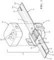
- the connector 10 is particularly suitable for use with flat wires.
- the connector 10 includes an insulative housing 12, which may be constructed from multiple plastic pieces, such as first and second housing portions 20, 22.
- the exemplary housing 12 may vary from the configuration depicted, particularly the second housing portion 22, which may be integrated with an electrical component such as a lighting device, sensor, electrical connector, or other electrical device.
- the second housing portion 22 includes electrical contacts provided by springs that supply electrical continuity between wiring 14 and the electrical component.
- the connector 10 is used in conjunction with wiring 14, which may include one or more wires 14a, 14b.
- Each wire includes a relatively flat conductor 16 that is generally rectangular and is encased in a non-conductive, flexible plastic insulation 18 to provide a cross-sectional aspect ratio of at least 2:1 with respect to the width and the height.
- "generally rectangular” includes any shape having a width greater than its height in cross section and may include rectangular, parallelogram, trapezoid, oval, obround, and elliptical shapes.
- the aspect ratio may be at least 3:1. In other embodiments, the aspect ratio may be at least 5:1.
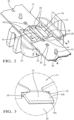
- the conductor 16 is provided by non-stranded electrically conductive material, such as a flat copper wire 16a plated with tin 16b ( Fig. 3 ).
- the adjacent wires 14a, 14b may be interconnected with insulation material that forms webbing 17, which provides structurally integrity to the wiring 14 during handling.
- the wires 14a, 14b have a stripped portion 24 that expose the conductors 16 at a longitudinal location defined by edges 26 of the insulation 18. That is, the stripped portions 24 are bounded by insulation 18 at either end.
- the first housing portion 20 includes a first set of barbs 28 spaced apart from a second set of barbs 30. The conductors 16 are clipped in beneath and retained by their respective sets of barbs.
- the first and second sets of barbs 28, 30 retain the stripped portions 24 longitudinally as well, such that the edges 26 are longitudinally located by the barbs to orient the wiring 14 in the desired position relative to the housing 12.
- the barbs 28, 30 overlay the stripped portions 24. In this manner, the edges 26 and barbs 28, 30 cooperate to provide locating features that interact with one another to secure the wiring 14 relative to housing 12.
- the insulation 18 may include one or more apertures that cooperates with a corresponding projection provided by a second locating feature of the housing 12.
- the apertures may be provided by small holes, while larger elongated openings 35 ( Fig. 1 ) may be provided in the insulation 18 to provide a type of dash-dot interruption in the webbing 17.
- More webbing 17 is provided near the housing 12 to provide improved structural integrity to the wiring 14, while larger elongated openings 35 in the webbing 17 may be provided elsewhere to increase flexibility for ease of handling and routing within a vehicle, for example.
- the wiring aperture is provided by a first aperture 36 between the wires 14a, 14b, which provides a break or interruption in the webbing 17, as shown in Figures 4 and 5 .
- a recess 32 is provided in the first housing portion 20 to laterally locate the wiring 14.
- the second locating feature is provided by a pin 34 on the first housing portion 20 that is covered by the second housing portion 22 in an assembled condition, shown in Figure 4 . In this manner, the wiring 14 is captured by the first and second housing portions 20, 22 using the insulation 18, but without putting strain on the conductors 16.
- the aperture is provided a second aperture 38 between the wires 14a, 14b.
- the second locating feature is provided by a protrusion 40 on the first housing portion 20 that is outside the second housing portion 22 in an assembled connector condition, as shown in Figure 4 .
- the protrusion 40 is longer than the pin 34, which enables the wiring 14 to be easily oriented with the first housing portion 20 early in the assembly process before the conductors 16 are inserted beneath the barbs 28, 30, for example.
- Locating features also may be provided by an aperture forming a notch 44 between wires 14a, 14b.
- the second locating feature is provided by a rib 42 on the first housing portion 20 that is arranged at the edge 26 of the insulation 18 at the stripped portion 24, best shown in Figures 2 and 4 .
- the aperture may be provided by a notch 144 at an outer edge of the insulation 118 of wiring 114, as shown in Figure 6 .
- a locating pin 134 is provided on the first housing portion 120 to cooperate with the notch 144.
- the various apertures and opening in the wiring 14 may be formed using various techniques. These holes may be laser cut, punched, formed during molding of the insulation 18, or by any other suitable technique prior to the installing the wiring into the housing 12.
- a method of assembling an electrical connector 10 includes a step of providing wiring 14 with multiple wires 14a, 14b. Each wire has a conductor 16 covered in insulation 18. Insulation 18 includes webbing 17 that interconnects the wire 14a, 14b to one another. The insulation 18 has an aperture (e.g., 36, 38, 44, 144) that provides a first locating feature. The wires have a stripped portion 24 exposing the conductors 16. Each of the wires 14a, 14b has a profile with a height in which the width is at least twice the height. The stripped portion 24 is mounted to the housing 12 with the second locating feature (e.g., 34, 40, 42, 134), and the second locating feature is positioned into the aperture of the first locating feature.
- the second locating feature e.g., 34, 40, 42, 134
- the first and second barbs 28, 30 provide a supplemental locating feature by retaining the stripped portions 24 of conductors 16 and by longitudinally abutting edges 26.
- the second housing portion 22 is secured to the first housing portion 20 using one or more snaps.
- the second housing portion may carry an electrical contact 23 that may be provided by one or more springs. The electrical contacts 23 engage the stripped portions 24 when the housing is in the assembled housing condition.
Landscapes
- Connections By Means Of Piercing Elements, Nuts, Or Screws (AREA)
- Multi-Conductor Connections (AREA)
Claims (12)
- Connecteur électrique (10), comprenant :un câblage (14) avec plusieurs fils (14a, 14b), chaque fil ayant un conducteur (16) recouvert d'isolant (18), l'isolant (18) comportant une sangle (17) qui interconnecte les fils (14a, 14b) les uns aux autres, l'isolant (18) ayant une ouverture fournissant une première caractéristique de positionnement, les fils (14a, 14b) ayant une partie dénudée (24) exposant les conducteurs (16) ; etun boîtier (12) recevant la partie dénudée (24), le boîtier (12) comportant une caractéristique de positionnement supplémentaire, dans lequel le boîtier (12) comporte des première et seconde parties de boîtier (20, 22) fixées l'une à l'autre autour de la partie dénudée (24), la première partie de boîtier (20) est configurée pour positionner solidement le câblage (14) par rapport au boîtier (12), et la seconde partie de boîtier (22) comporte un contact électrique venant en prise avec l'une des parties dénudées (24), caractérisé en ce que la caractéristique de positionnement supplémentaire comprend un premier ensemble de picots (28) espacés d'un second ensemble de picots (30), les premier et second ensembles de picots (28, 30) retenant les parties dénudées (24), et l'isolant (18) comportant des bords (26) adjacents aux premier et second ensembles de picots (28, 30) pour positionner longitudinalement le câblage (14) par rapport au boîtier (12).
- Connecteur électrique (10) selon la revendication 1, dans lequel le boîtier (12) comporte une saillie fournissant une seconde caractéristique de positionnement qui coopère avec la première caractéristique de positionnement pour orienter et positionner la partie dénudée (24) à l'intérieur du boîtier (12) .
- Connecteur électrique (10) selon l'une quelconque des revendications 1 et 2, dans lequel chaque conducteur (16) est formé d'un matériau conducteur solide non toronné et dans lequel chacun des conducteurs (16) a un profil généralement rectangulaire ayant une largeur et une hauteur, dans lequel la largeur est au moins le double de la hauteur.
- Connecteur électrique (10) selon la revendication 3, dans lequel la sangle (17) a une ouverture s'étendant longitudinalement (35) qui sépare les fils adjacents (14a).
- Connecteur électrique (10) selon la revendication 3, dans lequel l'isolant (18) est prévu de part et d'autre de l'une des parties dénudées (24).
- Connecteur électrique selon l'une des revendications 1 à 5, dans lequel la première partie de boîtier (20) comporte la caractéristique de positionnement supplémentaire.
- Connecteur électrique (10) selon l'une des revendications 1 à 6, dans lequel l'ouverture comporte une première ouverture (36) entre les fils (14a, 14b), et la seconde caractéristique de positionnement est fournie par une broche (34) sur la première partie de boîtier (20) qui est recouverte par la seconde partie de boîtier (22) dans un état de connecteur assemblé.
- Connecteur électrique (10) selon l'une des revendications 1 à 6, dans lequel l'ouverture comporte une seconde ouverture (38) entre les fils (14a, 14b), et la seconde caractéristique de positionnement est fournie par une saillie (40) sur la première partie de boîtier (20) qui se trouve à l'extérieur de la seconde partie de boîtier (22) dans un état de connecteur assemblé.
- Connecteur électrique (10) selon l'une des revendications 1 à 6, dans lequel l'ouverture est une encoche (44) entre les fils (14a, 14b), et la seconde caractéristique de positionnement est une nervure (42) sur la première partie de boîtier (20) agencée au niveau d'un bord de l'isolant (18) au niveau de la partie dénudée (24).
- Connecteur électrique (10) selon l'une des revendications 1 à 6, dans lequel l'ouverture est une encoche (144) agencée au niveau d'un bord extérieur de l'isolant (18), et le second de positionnement est une broche de positionnement (134) sur la première partie de boîtier (20).
- Procédé d'assemblage d'un connecteur électrique, comprenant les étapes de :fourniture d'un câblage (14) avec plusieurs fils (14a, 14b), chaque fil ayant un conducteur (16) recouvert d'isolant (18), l'isolant comporte une sangle (17) qui interconnecte les fils (14a, 14b) les uns aux autres, l'isolant (18) ayant une ouverture fournissant une première caractéristique de positionnement, les fils ayant une partie dénudée (24) exposant les conducteurs (16), et dans lequel chacun des conducteurs (16) a un profil généralement rectangulaire ayant une largeur et une hauteur, dans lequel la largeur est au moins le double de la hauteur ;montage de la partie dénudée (24) dans un boîtier (12) avec une seconde caractéristique de positionnement ; etpositionnement de la caractéristique de positionnement supplémentaire dans l'ouverture de la première caractéristique de positionnement,dans lequel le boîtier (12) est fourni par une première partie de boîtier (20), le procédé comprenant en outre une étape de fixation d'une seconde partie de boîtier (22) à la première partie de boîtier (20) et autour de la partie dénudée (24), dans lequel la seconde partie de boîtier (22) comporte un contact électrique (23) venant en prise avec la partie dénudée (24) pendant l'étape de fixation,caractérisé en ce que,l'étape de montage comporte la retenue de la partie dénudée (24) avec des premier et second ensembles de picots (28, 30) espacés l'un de l'autre, les premier et second ensembles de picots (28, 30) retenant la partie dénudée (24), et l'isolant (18) comportant des bords (26) adjacents aux premier et second ensembles de picots (28, 30) pour positionner longitudinalement le câblage (14) par rapport au boîtier (12).
- Procédé selon la revendication 11, dans lequel l'étape de fourniture comporte la formation de l'ouverture dans l'isolant (18) avant les étapes de montage et de positionnement.
Applications Claiming Priority (1)
| Application Number | Priority Date | Filing Date | Title |
|---|---|---|---|
| US16/670,147 US10958004B1 (en) | 2019-10-31 | 2019-10-31 | Location orientation of wiring relative to electrical connector |
Publications (2)
| Publication Number | Publication Date |
|---|---|
| EP3817151A1 EP3817151A1 (fr) | 2021-05-05 |
| EP3817151B1 true EP3817151B1 (fr) | 2023-07-05 |
Family
ID=73014417
Family Applications (1)
| Application Number | Title | Priority Date | Filing Date |
|---|---|---|---|
| EP20203773.5A Active EP3817151B1 (fr) | 2019-10-31 | 2020-10-26 | Orientation de localisation de câblage par rapport à un connecteur électrique |
Country Status (3)
| Country | Link |
|---|---|
| US (1) | US10958004B1 (fr) |
| EP (1) | EP3817151B1 (fr) |
| CN (1) | CN112751222B (fr) |
Family Cites Families (19)
| Publication number | Priority date | Publication date | Assignee | Title |
|---|---|---|---|---|
| GB1327194A (en) * | 1969-09-12 | 1973-08-15 | Pressac Ltd | Electrical connector for use with flat tape or striplike wiring conductors |
| US3999826A (en) * | 1975-06-30 | 1976-12-28 | General Motors Corporation | Connector for flexible printed circuit |
| US4196956A (en) * | 1975-09-02 | 1980-04-08 | Harvey Hubbell, Incorporated | Dead-front electrical connector |
| US4293177A (en) * | 1977-11-21 | 1981-10-06 | Amp Incorporated | Flat cable connector |
| US4406511A (en) * | 1981-07-29 | 1983-09-27 | Amp Incorporated | Flat cable connector strain relief |
| EP0393927B1 (fr) * | 1989-04-21 | 1994-11-09 | The Whitaker Corporation | Procédé de connexion de câbles de puissance plats |
| US5339232A (en) * | 1993-01-12 | 1994-08-16 | Lin Te H | Miniature light set |
| JP3143565B2 (ja) | 1994-02-28 | 2001-03-07 | キヤノン株式会社 | フレキシブルプリント配線、その接続装置、及び電気回路装置 |
| DE10116454C2 (de) * | 2001-04-03 | 2003-08-14 | Fci Automotive Deutschland Gmb | Verbindungsanordnung für Flex-Flachbandkabel |
| DE10121307C1 (de) * | 2001-05-02 | 2002-12-05 | Framatome Connectors Int | Verbindungssystem für Flex-Flachbandkabel mit Exzenter |
| DE10250924A1 (de) | 2002-10-31 | 2004-05-19 | Fci | Inline-Klemmverbinder für Flex-Flachbandkabel |
| DE10250933B3 (de) | 2002-10-31 | 2004-08-12 | Fci | Verbinderanordnung zwischen einem Flex-Flachbandkabel und einer elektrischen Leiterplatte |
| JP2006216490A (ja) * | 2005-02-07 | 2006-08-17 | Fujikura Ltd | フレキシブル配線板用コネクタ |
| JP4291800B2 (ja) | 2005-06-21 | 2009-07-08 | 日本圧着端子製造株式会社 | 電気的接続装置及びコネクタ |
| DE202005014718U1 (de) * | 2005-09-17 | 2007-02-01 | Weidmüller Interface GmbH & Co. KG | Anschluß-System zur Realisierung von Abzweigungen an durchgehenden Leitern |
| US7887351B2 (en) * | 2008-10-30 | 2011-02-15 | Taiwan Suncagey Industrial Co., Ltd. | Electrical connector for flat conductor |
| JP5736137B2 (ja) | 2010-08-17 | 2015-06-17 | 矢崎総業株式会社 | フラットケーブル用コネクタ |
| US9300066B2 (en) * | 2011-05-03 | 2016-03-29 | Cardioinsight Technologies, Inc. | High-voltage resistance and retention of printed flex circuits |
| US9360196B2 (en) * | 2012-06-15 | 2016-06-07 | Rtc Industries, Inc. | Low voltage power supply for a merchandise display system |
-
2019
- 2019-10-31 US US16/670,147 patent/US10958004B1/en active Active
-
2020
- 2020-10-26 EP EP20203773.5A patent/EP3817151B1/fr active Active
- 2020-10-30 CN CN202011188785.1A patent/CN112751222B/zh active Active
Also Published As
| Publication number | Publication date |
|---|---|
| CN112751222A (zh) | 2021-05-04 |
| EP3817151A1 (fr) | 2021-05-05 |
| US10958004B1 (en) | 2021-03-23 |
| CN112751222B (zh) | 2023-03-17 |
Similar Documents
| Publication | Publication Date | Title |
|---|---|---|
| US8043109B2 (en) | Wire to board connector | |
| EP0572052A1 (fr) | Distribution électrique centralisée | |
| EP2916398A1 (fr) | Raccord de borne | |
| US4721471A (en) | Power bus system for printed circuit boards | |
| US6319046B1 (en) | Electrical connection unit which can be used with both insulated and stripped leads | |
| JP2006505105A (ja) | 可撓性リボンケーブル用クランプコネクタ | |
| EP3817152A1 (fr) | Connecteur électrique perpendiculaire pour le câblage | |
| EP3465827A1 (fr) | Connecteur électrique enfichable | |
| JP2000100539A (ja) | コネクタ及びコネクタの製造方法 | |
| EP1117153B1 (fr) | Configuration protectrice pour de câbles plats | |
| EP3817149B1 (fr) | Connecteur d'épissure électrique | |
| US6626694B2 (en) | Insulation displacement electrical connector with contact retaining arms | |
| US9647357B2 (en) | Peg press-fitting structure for connector | |
| US10958004B1 (en) | Location orientation of wiring relative to electrical connector | |
| JP6908927B2 (ja) | 端子 | |
| JP4102295B2 (ja) | 同軸ケーブル用ピアシング端子 | |
| JPH11121108A (ja) | 回路基板用電気コネクタ | |
| US20250202136A1 (en) | Insulation displacement connector having a sleeve | |
| JPH1154217A (ja) | 回路基板用電気コネクタ | |
| JP7334648B2 (ja) | 圧接端子及び電子装置 | |
| EP4406068A1 (fr) | Coupleur de bobine incliné | |
| JP4305536B2 (ja) | 多極同軸コネクタ | |
| JP3367468B2 (ja) | 圧接端子 | |
| JPH062562U (ja) | 差込み型コネクタ | |
| JPH0757806A (ja) | コネクタ端子及びその使用方法 |
Legal Events
| Date | Code | Title | Description |
|---|---|---|---|
| PUAI | Public reference made under article 153(3) epc to a published international application that has entered the european phase |
Free format text: ORIGINAL CODE: 0009012 |
|
| STAA | Information on the status of an ep patent application or granted ep patent |
Free format text: STATUS: THE APPLICATION HAS BEEN PUBLISHED |
|
| AK | Designated contracting states |
Kind code of ref document: A1 Designated state(s): AL AT BE BG CH CY CZ DE DK EE ES FI FR GB GR HR HU IE IS IT LI LT LU LV MC MK MT NL NO PL PT RO RS SE SI SK SM TR |
|
| STAA | Information on the status of an ep patent application or granted ep patent |
Free format text: STATUS: REQUEST FOR EXAMINATION WAS MADE |
|
| 17P | Request for examination filed |
Effective date: 20211105 |
|
| RBV | Designated contracting states (corrected) |
Designated state(s): AL AT BE BG CH CY CZ DE DK EE ES FI FR GB GR HR HU IE IS IT LI LT LU LV MC MK MT NL NO PL PT RO RS SE SI SK SM TR |
|
| GRAP | Despatch of communication of intention to grant a patent |
Free format text: ORIGINAL CODE: EPIDOSNIGR1 |
|
| STAA | Information on the status of an ep patent application or granted ep patent |
Free format text: STATUS: GRANT OF PATENT IS INTENDED |
|
| INTG | Intention to grant announced |
Effective date: 20221021 |
|
| GRAJ | Information related to disapproval of communication of intention to grant by the applicant or resumption of examination proceedings by the epo deleted |
Free format text: ORIGINAL CODE: EPIDOSDIGR1 |
|
| STAA | Information on the status of an ep patent application or granted ep patent |
Free format text: STATUS: REQUEST FOR EXAMINATION WAS MADE |
|
| GRAS | Grant fee paid |
Free format text: ORIGINAL CODE: EPIDOSNIGR3 |
|
| STAA | Information on the status of an ep patent application or granted ep patent |
Free format text: STATUS: GRANT OF PATENT IS INTENDED |
|
| GRAP | Despatch of communication of intention to grant a patent |
Free format text: ORIGINAL CODE: EPIDOSNIGR1 |
|
| INTG | Intention to grant announced |
Effective date: 20230127 |
|
| RAP3 | Party data changed (applicant data changed or rights of an application transferred) |
Owner name: APTIV TECHNOLOGIES LIMITED |
|
| GRAA | (expected) grant |
Free format text: ORIGINAL CODE: 0009210 |
|
| STAA | Information on the status of an ep patent application or granted ep patent |
Free format text: STATUS: THE PATENT HAS BEEN GRANTED |
|
| AK | Designated contracting states |
Kind code of ref document: B1 Designated state(s): AL AT BE BG CH CY CZ DE DK EE ES FI FR GB GR HR HU IE IS IT LI LT LU LV MC MK MT NL NO PL PT RO RS SE SI SK SM TR |
|
| REG | Reference to a national code |
Ref country code: CH Ref legal event code: EP |
|
| REG | Reference to a national code |
Ref country code: AT Ref legal event code: REF Ref document number: 1585696 Country of ref document: AT Kind code of ref document: T Effective date: 20230715 |
|
| REG | Reference to a national code |
Ref country code: DE Ref legal event code: R096 Ref document number: 602020013243 Country of ref document: DE |
|
| REG | Reference to a national code |
Ref country code: IE Ref legal event code: FG4D |
|
| P01 | Opt-out of the competence of the unified patent court (upc) registered |
Effective date: 20230630 |
|
| REG | Reference to a national code |
Ref country code: LT Ref legal event code: MG9D |
|
| REG | Reference to a national code |
Ref country code: NL Ref legal event code: MP Effective date: 20230705 |
|
| REG | Reference to a national code |
Ref country code: AT Ref legal event code: MK05 Ref document number: 1585696 Country of ref document: AT Kind code of ref document: T Effective date: 20230705 |
|
| PG25 | Lapsed in a contracting state [announced via postgrant information from national office to epo] |
Ref country code: NL Free format text: LAPSE BECAUSE OF FAILURE TO SUBMIT A TRANSLATION OF THE DESCRIPTION OR TO PAY THE FEE WITHIN THE PRESCRIBED TIME-LIMIT Effective date: 20230705 |
|
| PG25 | Lapsed in a contracting state [announced via postgrant information from national office to epo] |
Ref country code: GR Free format text: LAPSE BECAUSE OF FAILURE TO SUBMIT A TRANSLATION OF THE DESCRIPTION OR TO PAY THE FEE WITHIN THE PRESCRIBED TIME-LIMIT Effective date: 20231006 |
|
| PG25 | Lapsed in a contracting state [announced via postgrant information from national office to epo] |
Ref country code: ES Free format text: LAPSE BECAUSE OF FAILURE TO SUBMIT A TRANSLATION OF THE DESCRIPTION OR TO PAY THE FEE WITHIN THE PRESCRIBED TIME-LIMIT Effective date: 20230705 |
|
| PG25 | Lapsed in a contracting state [announced via postgrant information from national office to epo] |
Ref country code: IS Free format text: LAPSE BECAUSE OF FAILURE TO SUBMIT A TRANSLATION OF THE DESCRIPTION OR TO PAY THE FEE WITHIN THE PRESCRIBED TIME-LIMIT Effective date: 20231105 |
|
| PG25 | Lapsed in a contracting state [announced via postgrant information from national office to epo] |
Ref country code: SE Free format text: LAPSE BECAUSE OF FAILURE TO SUBMIT A TRANSLATION OF THE DESCRIPTION OR TO PAY THE FEE WITHIN THE PRESCRIBED TIME-LIMIT Effective date: 20230705 Ref country code: RS Free format text: LAPSE BECAUSE OF FAILURE TO SUBMIT A TRANSLATION OF THE DESCRIPTION OR TO PAY THE FEE WITHIN THE PRESCRIBED TIME-LIMIT Effective date: 20230705 Ref country code: PT Free format text: LAPSE BECAUSE OF FAILURE TO SUBMIT A TRANSLATION OF THE DESCRIPTION OR TO PAY THE FEE WITHIN THE PRESCRIBED TIME-LIMIT Effective date: 20231106 Ref country code: NO Free format text: LAPSE BECAUSE OF FAILURE TO SUBMIT A TRANSLATION OF THE DESCRIPTION OR TO PAY THE FEE WITHIN THE PRESCRIBED TIME-LIMIT Effective date: 20231005 Ref country code: LV Free format text: LAPSE BECAUSE OF FAILURE TO SUBMIT A TRANSLATION OF THE DESCRIPTION OR TO PAY THE FEE WITHIN THE PRESCRIBED TIME-LIMIT Effective date: 20230705 Ref country code: LT Free format text: LAPSE BECAUSE OF FAILURE TO SUBMIT A TRANSLATION OF THE DESCRIPTION OR TO PAY THE FEE WITHIN THE PRESCRIBED TIME-LIMIT Effective date: 20230705 Ref country code: IS Free format text: LAPSE BECAUSE OF FAILURE TO SUBMIT A TRANSLATION OF THE DESCRIPTION OR TO PAY THE FEE WITHIN THE PRESCRIBED TIME-LIMIT Effective date: 20231105 Ref country code: HR Free format text: LAPSE BECAUSE OF FAILURE TO SUBMIT A TRANSLATION OF THE DESCRIPTION OR TO PAY THE FEE WITHIN THE PRESCRIBED TIME-LIMIT Effective date: 20230705 Ref country code: GR Free format text: LAPSE BECAUSE OF FAILURE TO SUBMIT A TRANSLATION OF THE DESCRIPTION OR TO PAY THE FEE WITHIN THE PRESCRIBED TIME-LIMIT Effective date: 20231006 Ref country code: FI Free format text: LAPSE BECAUSE OF FAILURE TO SUBMIT A TRANSLATION OF THE DESCRIPTION OR TO PAY THE FEE WITHIN THE PRESCRIBED TIME-LIMIT Effective date: 20230705 Ref country code: ES Free format text: LAPSE BECAUSE OF FAILURE TO SUBMIT A TRANSLATION OF THE DESCRIPTION OR TO PAY THE FEE WITHIN THE PRESCRIBED TIME-LIMIT Effective date: 20230705 Ref country code: AT Free format text: LAPSE BECAUSE OF FAILURE TO SUBMIT A TRANSLATION OF THE DESCRIPTION OR TO PAY THE FEE WITHIN THE PRESCRIBED TIME-LIMIT Effective date: 20230705 |
|
| PG25 | Lapsed in a contracting state [announced via postgrant information from national office to epo] |
Ref country code: PL Free format text: LAPSE BECAUSE OF FAILURE TO SUBMIT A TRANSLATION OF THE DESCRIPTION OR TO PAY THE FEE WITHIN THE PRESCRIBED TIME-LIMIT Effective date: 20230705 |
|
| REG | Reference to a national code |
Ref country code: DE Ref legal event code: R097 Ref document number: 602020013243 Country of ref document: DE |
|
| PG25 | Lapsed in a contracting state [announced via postgrant information from national office to epo] |
Ref country code: SM Free format text: LAPSE BECAUSE OF FAILURE TO SUBMIT A TRANSLATION OF THE DESCRIPTION OR TO PAY THE FEE WITHIN THE PRESCRIBED TIME-LIMIT Effective date: 20230705 Ref country code: RO Free format text: LAPSE BECAUSE OF FAILURE TO SUBMIT A TRANSLATION OF THE DESCRIPTION OR TO PAY THE FEE WITHIN THE PRESCRIBED TIME-LIMIT Effective date: 20230705 Ref country code: EE Free format text: LAPSE BECAUSE OF FAILURE TO SUBMIT A TRANSLATION OF THE DESCRIPTION OR TO PAY THE FEE WITHIN THE PRESCRIBED TIME-LIMIT Effective date: 20230705 Ref country code: DK Free format text: LAPSE BECAUSE OF FAILURE TO SUBMIT A TRANSLATION OF THE DESCRIPTION OR TO PAY THE FEE WITHIN THE PRESCRIBED TIME-LIMIT Effective date: 20230705 Ref country code: CZ Free format text: LAPSE BECAUSE OF FAILURE TO SUBMIT A TRANSLATION OF THE DESCRIPTION OR TO PAY THE FEE WITHIN THE PRESCRIBED TIME-LIMIT Effective date: 20230705 Ref country code: SK Free format text: LAPSE BECAUSE OF FAILURE TO SUBMIT A TRANSLATION OF THE DESCRIPTION OR TO PAY THE FEE WITHIN THE PRESCRIBED TIME-LIMIT Effective date: 20230705 |
|
| PLBE | No opposition filed within time limit |
Free format text: ORIGINAL CODE: 0009261 |
|
| STAA | Information on the status of an ep patent application or granted ep patent |
Free format text: STATUS: NO OPPOSITION FILED WITHIN TIME LIMIT |
|
| PG25 | Lapsed in a contracting state [announced via postgrant information from national office to epo] |
Ref country code: IT Free format text: LAPSE BECAUSE OF FAILURE TO SUBMIT A TRANSLATION OF THE DESCRIPTION OR TO PAY THE FEE WITHIN THE PRESCRIBED TIME-LIMIT Effective date: 20230705 Ref country code: MC Free format text: LAPSE BECAUSE OF FAILURE TO SUBMIT A TRANSLATION OF THE DESCRIPTION OR TO PAY THE FEE WITHIN THE PRESCRIBED TIME-LIMIT Effective date: 20230705 |
|
| REG | Reference to a national code |
Ref country code: CH Ref legal event code: PL |
|
| 26N | No opposition filed |
Effective date: 20240408 |
|
| REG | Reference to a national code |
Ref country code: BE Ref legal event code: MM Effective date: 20231031 |
|
| PG25 | Lapsed in a contracting state [announced via postgrant information from national office to epo] |
Ref country code: LU Free format text: LAPSE BECAUSE OF NON-PAYMENT OF DUE FEES Effective date: 20231026 |
|
| PG25 | Lapsed in a contracting state [announced via postgrant information from national office to epo] |
Ref country code: LU Free format text: LAPSE BECAUSE OF NON-PAYMENT OF DUE FEES Effective date: 20231026 |
|
| PG25 | Lapsed in a contracting state [announced via postgrant information from national office to epo] |
Ref country code: CH Free format text: LAPSE BECAUSE OF NON-PAYMENT OF DUE FEES Effective date: 20231031 |
|
| PG25 | Lapsed in a contracting state [announced via postgrant information from national office to epo] |
Ref country code: CH Free format text: LAPSE BECAUSE OF NON-PAYMENT OF DUE FEES Effective date: 20231031 Ref country code: SI Free format text: LAPSE BECAUSE OF FAILURE TO SUBMIT A TRANSLATION OF THE DESCRIPTION OR TO PAY THE FEE WITHIN THE PRESCRIBED TIME-LIMIT Effective date: 20230705 |
|
| PG25 | Lapsed in a contracting state [announced via postgrant information from national office to epo] |
Ref country code: BE Free format text: LAPSE BECAUSE OF NON-PAYMENT OF DUE FEES Effective date: 20231031 |
|
| PG25 | Lapsed in a contracting state [announced via postgrant information from national office to epo] |
Ref country code: IE Free format text: LAPSE BECAUSE OF NON-PAYMENT OF DUE FEES Effective date: 20231026 |
|
| PG25 | Lapsed in a contracting state [announced via postgrant information from national office to epo] |
Ref country code: IE Free format text: LAPSE BECAUSE OF NON-PAYMENT OF DUE FEES Effective date: 20231026 |
|
| PG25 | Lapsed in a contracting state [announced via postgrant information from national office to epo] |
Ref country code: BG Free format text: LAPSE BECAUSE OF FAILURE TO SUBMIT A TRANSLATION OF THE DESCRIPTION OR TO PAY THE FEE WITHIN THE PRESCRIBED TIME-LIMIT Effective date: 20230705 |
|
| PG25 | Lapsed in a contracting state [announced via postgrant information from national office to epo] |
Ref country code: BG Free format text: LAPSE BECAUSE OF FAILURE TO SUBMIT A TRANSLATION OF THE DESCRIPTION OR TO PAY THE FEE WITHIN THE PRESCRIBED TIME-LIMIT Effective date: 20230705 |
|
| REG | Reference to a national code |
Ref country code: DE Ref legal event code: R081 Ref document number: 602020013243 Country of ref document: DE Owner name: APTIV TECHNOLOGIES AG, CH Free format text: FORMER OWNER: APTIV TECHNOLOGIES LIMITED, ST. MICHAEL, BB |
|
| PG25 | Lapsed in a contracting state [announced via postgrant information from national office to epo] |
Ref country code: CY Free format text: LAPSE BECAUSE OF FAILURE TO SUBMIT A TRANSLATION OF THE DESCRIPTION OR TO PAY THE FEE WITHIN THE PRESCRIBED TIME-LIMIT; INVALID AB INITIO Effective date: 20201026 |
|
| PG25 | Lapsed in a contracting state [announced via postgrant information from national office to epo] |
Ref country code: HU Free format text: LAPSE BECAUSE OF FAILURE TO SUBMIT A TRANSLATION OF THE DESCRIPTION OR TO PAY THE FEE WITHIN THE PRESCRIBED TIME-LIMIT; INVALID AB INITIO Effective date: 20201026 |
|
| PG25 | Lapsed in a contracting state [announced via postgrant information from national office to epo] |
Ref country code: TR Free format text: LAPSE BECAUSE OF FAILURE TO SUBMIT A TRANSLATION OF THE DESCRIPTION OR TO PAY THE FEE WITHIN THE PRESCRIBED TIME-LIMIT Effective date: 20230705 |
|
| PGFP | Annual fee paid to national office [announced via postgrant information from national office to epo] |
Ref country code: DE Payment date: 20250917 Year of fee payment: 6 |
|
| PGFP | Annual fee paid to national office [announced via postgrant information from national office to epo] |
Ref country code: GB Payment date: 20251015 Year of fee payment: 6 |
|
| PGFP | Annual fee paid to national office [announced via postgrant information from national office to epo] |
Ref country code: FR Payment date: 20251014 Year of fee payment: 6 |