EP3817157A1 - Kontaktanordnung für einen steckverbinder, steckverbinder - Google Patents
Kontaktanordnung für einen steckverbinder, steckverbinder Download PDFInfo
- Publication number
- EP3817157A1 EP3817157A1 EP19206613.2A EP19206613A EP3817157A1 EP 3817157 A1 EP3817157 A1 EP 3817157A1 EP 19206613 A EP19206613 A EP 19206613A EP 3817157 A1 EP3817157 A1 EP 3817157A1
- Authority
- EP
- European Patent Office
- Prior art keywords
- contact
- plane
- subset
- elements
- contact elements
- Prior art date
- Legal status (The legal status is an assumption and is not a legal conclusion. Google has not performed a legal analysis and makes no representation as to the accuracy of the status listed.)
- Pending
Links
- 239000000463 material Substances 0.000 claims description 3
- 239000004033 plastic Substances 0.000 claims description 3
- 230000005540 biological transmission Effects 0.000 description 9
- KENZYIHFBRWMOD-UHFFFAOYSA-N 1,2-dichloro-4-(2,5-dichlorophenyl)benzene Chemical compound ClC1=CC=C(Cl)C(C=2C=C(Cl)C(Cl)=CC=2)=C1 KENZYIHFBRWMOD-UHFFFAOYSA-N 0.000 description 4
- 238000004519 manufacturing process Methods 0.000 description 4
- 239000002184 metal Substances 0.000 description 3
- 238000000034 method Methods 0.000 description 3
- 238000005520 cutting process Methods 0.000 description 2
- 230000000694 effects Effects 0.000 description 2
- 238000004080 punching Methods 0.000 description 2
- 239000000243 solution Substances 0.000 description 2
- WYVBETQIUHPLFO-UHFFFAOYSA-N 1,2-dichloro-4-(2,6-dichlorophenyl)benzene Chemical compound C1=C(Cl)C(Cl)=CC=C1C1=C(Cl)C=CC=C1Cl WYVBETQIUHPLFO-UHFFFAOYSA-N 0.000 description 1
- 238000006243 chemical reaction Methods 0.000 description 1
- 230000008878 coupling Effects 0.000 description 1
- 238000010168 coupling process Methods 0.000 description 1
- 238000005859 coupling reaction Methods 0.000 description 1
- 238000011161 development Methods 0.000 description 1
- 230000018109 developmental process Effects 0.000 description 1
- 238000001746 injection moulding Methods 0.000 description 1
- 239000002991 molded plastic Substances 0.000 description 1
- 238000000465 moulding Methods 0.000 description 1
Images



















Classifications
-
- H—ELECTRICITY
- H01—ELECTRIC ELEMENTS
- H01R—ELECTRICALLY-CONDUCTIVE CONNECTIONS; STRUCTURAL ASSOCIATIONS OF A PLURALITY OF MUTUALLY-INSULATED ELECTRICAL CONNECTING ELEMENTS; COUPLING DEVICES; CURRENT COLLECTORS
- H01R13/00—Details of coupling devices of the kinds covered by groups H01R12/70 or H01R24/00 - H01R33/00
- H01R13/646—Details of coupling devices of the kinds covered by groups H01R12/70 or H01R24/00 - H01R33/00 specially adapted for high-frequency, e.g. structures providing an impedance match or phase match
- H01R13/6461—Means for preventing cross-talk
-
- H—ELECTRICITY
- H01—ELECTRIC ELEMENTS
- H01R—ELECTRICALLY-CONDUCTIVE CONNECTIONS; STRUCTURAL ASSOCIATIONS OF A PLURALITY OF MUTUALLY-INSULATED ELECTRICAL CONNECTING ELEMENTS; COUPLING DEVICES; CURRENT COLLECTORS
- H01R13/00—Details of coupling devices of the kinds covered by groups H01R12/70 or H01R24/00 - H01R33/00
- H01R13/02—Contact members
-
- H—ELECTRICITY
- H01—ELECTRIC ELEMENTS
- H01R—ELECTRICALLY-CONDUCTIVE CONNECTIONS; STRUCTURAL ASSOCIATIONS OF A PLURALITY OF MUTUALLY-INSULATED ELECTRICAL CONNECTING ELEMENTS; COUPLING DEVICES; CURRENT COLLECTORS
- H01R13/00—Details of coupling devices of the kinds covered by groups H01R12/70 or H01R24/00 - H01R33/00
- H01R13/46—Bases; Cases
- H01R13/502—Bases; Cases composed of different pieces
-
- H—ELECTRICITY
- H01—ELECTRIC ELEMENTS
- H01R—ELECTRICALLY-CONDUCTIVE CONNECTIONS; STRUCTURAL ASSOCIATIONS OF A PLURALITY OF MUTUALLY-INSULATED ELECTRICAL CONNECTING ELEMENTS; COUPLING DEVICES; CURRENT COLLECTORS
- H01R13/00—Details of coupling devices of the kinds covered by groups H01R12/70 or H01R24/00 - H01R33/00
- H01R13/62—Means for facilitating engagement or disengagement of coupling parts or for holding them in engagement
- H01R13/639—Additional means for holding or locking coupling parts together, after engagement, e.g. separate keylock, retainer strap
-
- H—ELECTRICITY
- H01—ELECTRIC ELEMENTS
- H01R—ELECTRICALLY-CONDUCTIVE CONNECTIONS; STRUCTURAL ASSOCIATIONS OF A PLURALITY OF MUTUALLY-INSULATED ELECTRICAL CONNECTING ELEMENTS; COUPLING DEVICES; CURRENT COLLECTORS
- H01R13/00—Details of coupling devices of the kinds covered by groups H01R12/70 or H01R24/00 - H01R33/00
- H01R13/646—Details of coupling devices of the kinds covered by groups H01R12/70 or H01R24/00 - H01R33/00 specially adapted for high-frequency, e.g. structures providing an impedance match or phase match
- H01R13/6473—Impedance matching
Definitions
- the invention relates to a contact arrangement for a connector, and a connector.
- An object of the invention is to provide a solution that allows higher transmission rates.
- a contact arrangement for a connector comprising a plurality of contact elements, each of the contact elements extending from a first connection side to a second connection side, wherein at the first connection side first end sections of a first subset of the contact elements are configured to contact external elements in a first plane and first end sections of a second subset of the contact elements are configured to contact external elements in a second plane that is parallel to and spaced from the first plane along a height direction, and wherein at a compensation area intermediate sections of at least some of the contact elements lie in a single common plane.
- a connector according to the invention comprises such a contact arrangement.
- the first and the second subset can contain all the contact elements. No further contact elements can be present in the connector in such a case.
- the connector can comprise further contact elements, for example contact elements for signals that do not require a high transmission rate, or contact elements for other purposes such as power supply or grounding.
- the first and the second subset can contain all the contact elements for high transmission signals.
- the further contact elements do not necessarily have to be configured according to the inventive idea.
- the intermediate sections of a majority of both subsets can lie in a single common plane. This can already improve the transmission performance.
- the intermediate sections can lie in two planes.
- the intermediate sections can alternatingly lie in two planes.
- the intermediate sections of all contact elements and/or of both subsets can lie in a single common plane, depending on the requirements of possibly present further contact elements.
- the intermediate section can be arranged between two steps in the contact element to allow an easy manufacturing.
- a step can be a section in which the contact element changes from one plane to another plane.
- a step can comprise two bends, which can in particular turn in opposite ways, for example left and right or clockwise and counterclockwise.
- steps on two sides of the intermediate section can extend in opposite directions in the height direction away from the intermediate section. For example, one step can extend towards the first plane and the other step can extend away from the first plane.
- the intermediate sections can extend along at least a tenth of the total length of the contact elements.
- the intermediate sections extend along at least 20 %, more preferably along at least 30 % of the total length of the contact elements.
- a length of one intermediate section can thus be 10 %, 20 % or 30 % of the total length of the contact element.
- the total length can be measured along the curved or bent extent of the contact element.
- a distance between the first end section and the intermediate section can be less than a third of the total length of the contact element.
- the distance is less than 20 %, more preferably less than 10 % of the total length.
- the contact element can comprise a contact surface for contacting the external element.
- the contact surface can comprise a contact point.
- the contact surface can be curved, for example cylindrical and/or convex.
- the contact point can for example be the outmost point of the contact surface in the height direction.
- a plurality of the contact points on different contact elements can define the first plane and/or the second plane. The plurality of the contact points on different contact elements can lie within the first plane and/or the second plane.
- At least one of the contact elements comprises a first contact surface on the first connection side and a second contact surface on the second connection side, wherein the first contact surface and the second contact surface face in the same direction. A torque acting on the contact element can thus be reduced.
- the first contact surface can be arranged on the first end section.
- the second contact surface can be arranged on the second end section.
- face can mean that a vector that is perpendicular to the surface points away from the surface in a certain direction.
- the vector can in particular be defined in the contact point.
- At least one of the contact elements comprises a first contact surface on the first connection side and a second contact surface on the second connection side, wherein the first contact surface and the second contact surface face in opposite directions.
- first and the second contact surface can face 180° relative to each other.
- second end sections of the contact elements at the second connection side can be configured to contact external elements in a single plane.
- second end sections of a third subset of the contact elements are configured to contact external elements in a third plane and second end sections of a fourth subset of the contact elements are configured to contact external elements in a fourth plane that is parallel to and spaced from the third plane along the height direction or a further height direction.
- the third subset can be (i.e. comprise the same contact elements as) the first subset, and/or the fourth subset can be the second subset. This can make manufacturing simple.
- the contact elements of the first subset and the second subset may be in particular pairwise overlapping and/or be opposite one another in a direction perpendicular to the first and/or second plane.
- the contact elements of the third and fourth subset may be in particular pairwise overlapping and/or be opposite one another in a direction perpendicular to the third and fourth plane.
- the third subset comprises a subset of the first subset and a subset of the second subset and/or the fourth subset comprises a subset of the first subset and a subset of the second subset.
- At least one, preferably exactly one, contact element of the first subset and at least one, preferably exactly one, contact element of the second subset may swap positions at the second connection side with respect to the direction perpendicular to the first and/or second plane.
- each of the two contact elements crosses an intermediate plane extending between and parallel to the first and second plane once or an uneven number of times.
- the two swapped contact elements are located opposite one another at at least one of the first and second end with respect to e.g. the intermediate plane.
- the common plane of the intermediate sections is different from the first, the second, the third and/or the fourth plane.
- the plane of the intermediate sections can be located centrally between the first, the second, the third and/or the fourth plane.
- the plane of the intermediate sections can lie between the first and the second plane and/or between the third and the fourth plane.
- the plane of the intermediate sections can lie halfway between the first and the second plane and/or halfway between the third and the fourth plane.
- the plane of the intermediate sections can lie between the first and the second plane and/or between the third and the fourth plane, but shifted away from the exact middle plane between the two respective planes.
- the contact elements can be elongated elements.
- the contact elements can be strip-shaped. They can be made from sheet metal, for example by cutting and/or punching.
- the first end sections, the second end sections and the intermediate sections can be substantially planar or straight.
- the contact elements can extend along a longitudinal direction.
- the contact elements can run parallel in the longitudinal direction, at least in sections.
- the intermediate sections can be parallel to each other.
- first end sections can be parallel to each other and/or the second end sections can be parallel to each other.
- the first end sections of one subset for example of the first subset or the second subset, can substantially lie in a common plane that is parallel to the first and/or the second plane.
- At least one of the pluralities of the first end sections, the second end sections and the intermediate sections can be parallel to at least one of the other pluralities. This can further improve the assembling process.
- the pluralities of the first end sections, the second end sections and the intermediate sections can be tilted relative to at least one of the other pluralities.
- the intermediate sections may be tilted with respect to at least one of the first end section and the second end section, or with respect to at least one of the first, second, third and fourth plane.
- connection section connecting the first end section to the intermediate section extends perpendicular to the plane of the intermediate sections. This can improve the transmission performance.
- connection section connecting the second end section to the intermediate section extends perpendicular to the plane of the intermediate sections.
- connection sections extend perpendicular to the plane of the intermediate sections.
- the common plane of the intermediate sections can be parallel to the first, the second, the third and/or the fourth plane.
- the common plane of the intermediate sections can be tilted or at an angle to the first, the second, the third and/or the fourth plane. Further, the first and the second plane can be tilted or at an angle to the third and/or the fourth plane.
- the contact elements each only comprise the first end section, the first connection section, the intermediate section, the second connection section and the second end section. Preferably, each contact element is a monolithic element comprising only a single element.
- the third plane and/or the fourth plane can be perpendicular to the first plane and/or the second place.
- the second end sections can extend along the height direction.
- the second end sections of the third subset and the fourth subset can extend at 180 degrees to each other away from the first plane and/or the second plane.
- the intermediate sections of at least one subset can merge into and may not be separated from the first end sections and/or the second end sections, for example by steps.
- the contact elements can advantageously be embedded in a plastic material, for example in an injection-moulded plastic. This can result in a light-weight connector.
- the contact arrangement can comprise a fifth subset of contact elements that preferably are mechanically coupled to each other and a sixth subset of contact elements that preferably are mechanically coupled to each other. This can allow a simple handling of the contact elements of the fifth and the sixth subset.
- the fifth subset is supported in a first support piece and the sixth subset is supported in a second support piece. This can make the assembling process easy.
- the fifth subset can be the first and/or the third subset.
- the sixth subset can be the second and/or the fourth subset.
- the contact elements in the fifth subset and the sixth subset can have an identical shape but be arranged rotated by 180° relative to the other subset, in particular in the assembled state.
- the contact elements in the first and the second subset can have an identical shape and be rotated 180° to each other in the assembled state.
- At least one of the fifth and the sixth subset comprises two contact elements that differ in the orientation of the first contact surface and/or the second contact surface.
- the first support piece and/or the second support piece can comprise positioning elements for positioning the two pieces relative to each other.
- the connector can comprise a housing for keeping the two support pieces together.
- Fig. 1 shows a general layout of a connector 900.
- the connector 900 comprises several contact elements 10 made from sheet metal by cutting and/or punching.
- the contact elements 10 each extend from a first connection side 11 to a second connection side 12 in order to contact different external elements.
- the connector 900 can be an input/output connector like an RJ45-connector.
- a fifth subset 500 of the contact elements 10 is held in a first support piece 910, a sixth subset 600 of the contact elements 10 is held in a second support piece 920 that can be joined with the first support piece 910.
- the contact elements are mechanically coupled to each other by the support piece 910, 920.
- the first and second support piece 910, 920 make up a first piece 930 and a second piece 940 of the connector 900 that can be joined along a height direction H and held together by a housing 980.
- the resulting assembly can then be inserted into a shielding 990.
- the first support piece 910, the second support piece 920 and the housing 980 can be made from a plastic material, for example by injection moulding.
- the contact elements 10 each extend along a longitudinal or length direction L that is perpendicular to the height direction H.
- at least first end sections 21 of the contact elements 10 are arranged behind each other along a transverse direction T that is perpendicular to the height direction H and transverse to the length direction L.
- the contact elements 10 have shapes that allow them to be held in the first and the second support piece 910 and 920 by a positive fit without the need for further holding elements like latches.
- Fig. 4 shows the two pieces 930, 940 in a semi-finished state. Frames 960 of the moulding process are still present. It can further be seen that the contact elements 10 are embedded in the first and second support pieces 910, 920.
- first end sections 21 of a first subset 100 of the contact elements 10 are configured to contact the external elements in a first plane 810 and first end section 21 of a second subset 200 of the contact elements 10 are configured to contact the external elements in a second plane 820.
- the first subset 100 is also the fifth subset 500 referred to in Fig. 1 .
- the second subset 200 is identical to the sixth subset 600 referred to in Fig. 1 .
- positioning elements 950 are present on the first and the second piece 930, 940.
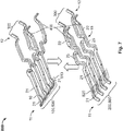
- Fig. 6 the two pieces 930, 940 are joined together.
- An external element can be inserted between the first end sections 21 of the contact elements 10 and the contact elements 10 then contact this external element on two opposite sides.
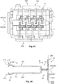
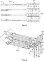
- the contact elements 10 are shown without the support pieces 910, 920. It can be seen that at the first connection side 11, the first end sections 21 of the contact elements 10 are grouped in the first subset 100 and the second subset 200. At a second connection side 12, the second end sections 22 of a subset of the first subset 100 and subset of the second subset 200 are configured to contact the external element at a third plane 830. The remaining contact elements 10 of the first subset 100 and the second subset 200 are configured to contact the external element at a fourth plane 840.
- the planes 810, 820, 830, 840 can here be defined by contact points 52 located on the contact surfaces 51.
- the contact surfaces 51 can be bent, for example convex, arc-shaped, cylindrical or similar.
- all the intermediate sections 25 of the contact elements 10 are configured or adapted to lie in a plane 880 in an assembled state.
- all of the intermediate sections 25 of the contact elements 10 lie in this plane 880 in the assembled state. This results in a good signal performance, as a cross talk between the contact elements 10 is minimized. Thus, the transmission rate can be high.
- the first plane 810 is spaced from the second plane 820 by a distance 751 along the height direction H.
- the third plane 830 is spaced from the fourth plane 840 by a distance 752 along the height direction H.
- the plane 880 is located approximately centrally between the first plane 810 and the second plane 820 and approximately centrally between the third plane 830 and the fourth plane 840.
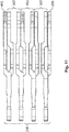
- the intermediate sections 25 of the contact elements are all parallel to each other and arranged behind each other in the transverse direction T.
- the contact elements 10 each only comprise the first end section 21, the first connection section 31, the intermediate section 15, the second connection section 32 and the second end section 22.
- Each contact element 10 is a monolithic element comprising only a single element, namely a metal strip.
- Fig. 13 the change of the lines 1 to 8 due to the contact arrangement 800 can be seen in the comparison between the configuration on the left-hand side and the configuration in the middle. It can be seen that the positions of lines 1 and 2 and the positions of lines 5 and 6 are swapped.
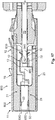
- FIGs. 16A, 16B and 16C in particular show sections through the connector along the planes indicated by A, B and C in Fig. 15 . While in the section across C, the cross sections of the contact elements 10 are located in two planes 810 and 820; they lie in a single common plane 880 in the cross section along plane B. In the section along plane A, the cross sections of the contact elements 10 again lie in two different planes 830, 840.
- Fig. 17 and 18 the configurations of two specific contact elements 10 are shown.
- the course of the contact element 10 goes from the second plane 820 to the common plane 880 and then to the third plane 830.
- Fig. 18 the course of a different contact element 10 goes from the first plane 810 to the common plane 880 and then to the fourth plane 840. Both are at the compensation area 15 that is located between the first connection side 11 and second connection side 12 at least in the area of the intermediate section 25 located in the common single plane 880.
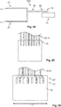
- FIGs. 19 and 20 two contact elements 10 are depicted that have a different reaction behavior towards external contact forces 18. While in Fig. 19 both contact surfaces 51, 51A, 51B at the first end section 21 and the second end section 22 face along the height direction H, the contact surfaces 51, 51A, 51B in the embodiment of Fig. 20 face in opposite directions.
- the contact surface 51, 51A at the first end section 21 faces in the height direction H while the contact surface 51, 51B at the second end section 22 faces against the height direction H.
- An advantage of the configuration in Fig. 19 is that the contact forces 80 act in the same direction and thus a torque acting on the contact element 10 is minimized.
- the two steps shown in Fig. 20 go in different directions relative to the intermediate section 25. While one of the steps 60 goes upwards, the other one goes downwards.
- a first group of contact arrangements 800 is depicted. This group has in common that at the second end section 22 a PCB 70 is contacted on two opposite sides.
- the contact elements 10 are arranged in an alternating manner.
- two neighboring contact elements 10 are paired and contact the same side of the PCB 70.
- a second group of contact arrangements 800 is shown. This group has in common that at the second end section 22, only one side of a PCB 70 is contacted.
- the difference between the embodiments shown in Figs. 25 and 26 is that the contact elements 10 are spaced further apart from each other on the PCB 70 at the second connection side 12 in order to reduce a cross talk.
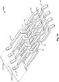
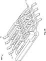
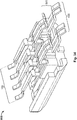
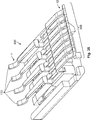
- Fig. 22 is shown in more detail in Figs. 27 to 30 .
- all the contact elements 10 are identical.
- Each of the contact elements 10 is, however, rotated 180° around the longitudinal or length direction L to the neighboring contact elements 10 so that a first subset 100 of the contact elements 10 associated with the first plane 810 comprises the same contact elements as the third subset of contact elements 10 associated with the third plane 830.
- the second subset 200 associated with the second plane 870 comprises the same contact element 10 as the fourth subset 400 associated with the fourth plane 840.
- all of the intermediate sections 25 of the contact elements 10 lie in a common plane 880 in the compensation area 15.
- the intermediate section 15 of each contact element can preferably extend along a length 725 that is at least 10 %, preferably 20 %, more preferably 30 % of a total length 710 of the contact element 10.
- the total length 710 can be measured along the bent course of the contact element 10and can in particular comprise the length 721 of the first end section 21, the length 722 of the second end section 22, the length 725 of the intermediate section 25 and the lengths 731, 732 of the two connection sections 31, 32.
- a distance between the first end section 21 and the intermediate section 25 and/or a distance between the second end section 22 and the intermediate section 22, which in this case corresponds substantially to the lengths 731, 732 of the two connection sections 31, 32, is preferably less than one third, more preferred less than 20 %, in particular less than 10 % of the total length 710.
- the distance can in particular be defined as the distance between the ends of two straight sections.
- the subset 300 associated with the third plane 830 comprises contact elements 10 from the first subset 100 and the second subset 200.
- the subset 400 associated with the fourth plane 840 comprises contact elements 10 from the first subset 100 and the second subset 200.
- the combination of the first subset 100 and the second subset 200 as well as a combination of the subset 300 and subset 400 comprises all the contact elements 10 of the contact arrangement 800.
- further contact elements 10 could be present, for example if the advantages associated with the inventive idea are not necessary.
- Such further contact elements 10 could, for example, be used for power supply or for low transmission rates.
- a further embodiment of a contact arrangement 800 is shown.
- the second end sections 22 of the contact elements 10 are configured to contact a single plane 830.
- the third subset 300 thus comprises all the contact elements 10 from the first subset 100 and the second subset 200.
- Figs. 39 to 42 further possible embodiments are shown schematically.
- the common plane 880 of the intermediate sections 25 lies between the first plane 810 and the second plane 820 and between the third plane 830 and the fourth plane 840, but shifted away from the exact middle plane 890 between the two respective planes 810, 820, 830, 840.
- the common plane 880 of the intermediate sections 25 is tilted or at an angle 895 to the first plane 810, the second plane 820, the third plane 830, the fourth plane 840 and the middle plane 890.
- the common plane 880 of the intermediate sections 25 is again tilted or at an angle 895 to the first plane 810, the second plane 820, and the middle plane 890.
- the common plane 880 is parallel to the third plane 830 and the fourth plane 840.
- the pluralities of the first end sections are tilted or at an angle to the pluralities of the second end sections 22 and the intermediate sections 25.
- Fig. 42 shows a cross section at the compensation area 15 of a further embodiment.
- some intermediate sections 25 lie in a first common plane 880, 881, while other intermediate sections 25 lie in a second common plane 880, 882.
- the two planes 880, 881, 882 lie shifted towards each other with a central plane 891 between them.
- the intermediate sections are alternatingly arranged in the first common plane 880, 881 and the second common plane 880, 882 to enlarge the distance between two neighboring intermediate sections 25 and to thus to variate the amount of coupling between them.
- a further embodiment of a contact arrangement 800 is shown.
- second end sections 22 of a third subset 300 of the contact elements 10 are configured to contact external elements in a third plane 830 and second end sections 22 of a fourth subset 400 of the contact elements 10 are configured to contact external elements in a fourth plane 840.
- the fourth plane 840 is identical to the third plane 830.
- the third plane 830 is perpendicular to the first plane 810 and the second place 820.
- the second end sections 22 extend along the height direction H. However, the second end sections 22 of the third subset 300 and the fourth subset 400 extend at 180 degrees to each other away from the first plane 810 and the second plane 820.
- the first subset 100 is identical to the third subset 300
- the second subset 200 is identical to the fourth subset 400.
- Intermediate sections 25 of the first subset 100 lie in a first common plane 880, 881.
- Intermediate sections 25 of the second subset 200 lie in a second common plane 880, 882, that is spaced from the first common plane 880, 881 in the height direction H.
- a further embodiment of a contact arrangement 800 is shown.
- second end sections 22 of a third subset 300 of the contact elements 10 are configured to contact external elements in a third plane 830 and second end sections 22 of a fourth subset 400 of the contact elements 10 are configured to contact external elements in a fourth plane 840.
- the fourth plane 840 is identical to the third plane 830.
- the third plane 830 is perpendicular to the first plane 810 and the second place 820.
- the second end sections 22 extend along the height direction H. However, the second end sections 22 of the third subset 300 and the fourth subset 400 extend at 180 degrees to each other away from the first plane 810 and a second plane 820.
- the first subset 100 is not identical to the third subset 300
- the second subset 200 is not identical to the fourth subset 400.
- one contact element 10 of the first subset 100 is not part of the third subset 300 but part of the fourth subset 400
- one contact element 10 of the second subset 200 is not part of the fourth subset 400 but part of the third subset 300
- a further embodiment of a contact arrangement 800 is shown.
- second end sections 22 of a third subset 300 of the contact elements 10 are configured to contact external elements in a third plane 830 and second end sections 22 of a fourth subset 400 of the contact elements 10 are configured to contact external elements in a fourth plane 840.
- the fourth plane 840 is identical to the third plane 830.
- the third plane is perpendicular to the first plane 810 and the second place 820.
- the second end sections 22 extend along the height direction H.
- the second end sections 22 of the third subset 300 and the fourth subset 400 extend at 180 degrees to each other away from the first plane 810 and a second plane 820.
- the first subset 100 is again identical to the third subset 300
- the second subset 200 is identical to the fourth subset 400.
- Intermediate sections 25 of the first subset 100 lie in a first common plane 880, 881.
- Intermediate sections 25 of the second subset 200 lie in a second common plane 880, 882, that is spaced from the first common plane 880, 881 in the height direction H.
- the intermediate sections 25 of the second subset are not separated from the first end sections 21 by steps.
Landscapes
- Coupling Device And Connection With Printed Circuit (AREA)
- Details Of Connecting Devices For Male And Female Coupling (AREA)
Priority Applications (5)
| Application Number | Priority Date | Filing Date | Title |
|---|---|---|---|
| EP19206613.2A EP3817157A1 (de) | 2019-10-31 | 2019-10-31 | Kontaktanordnung für einen steckverbinder, steckverbinder |
| JP2022524633A JP7353481B2 (ja) | 2019-10-31 | 2020-10-28 | コネクタ用コンタクト配置、コネクタ |
| CN202080075516.6A CN114616722B (zh) | 2019-10-31 | 2020-10-28 | 用于连接器的接触装置、连接器 |
| PCT/EP2020/080222 WO2021083924A1 (en) | 2019-10-31 | 2020-10-28 | Contact arrangement for a connector, connector |
| US17/732,095 US12255423B2 (en) | 2019-10-31 | 2022-04-28 | Contact arrangement for a connector, connector |
Applications Claiming Priority (1)
| Application Number | Priority Date | Filing Date | Title |
|---|---|---|---|
| EP19206613.2A EP3817157A1 (de) | 2019-10-31 | 2019-10-31 | Kontaktanordnung für einen steckverbinder, steckverbinder |
Publications (1)
| Publication Number | Publication Date |
|---|---|
| EP3817157A1 true EP3817157A1 (de) | 2021-05-05 |
Family
ID=68426134
Family Applications (1)
| Application Number | Title | Priority Date | Filing Date |
|---|---|---|---|
| EP19206613.2A Pending EP3817157A1 (de) | 2019-10-31 | 2019-10-31 | Kontaktanordnung für einen steckverbinder, steckverbinder |
Country Status (5)
| Country | Link |
|---|---|
| US (1) | US12255423B2 (de) |
| EP (1) | EP3817157A1 (de) |
| JP (1) | JP7353481B2 (de) |
| CN (1) | CN114616722B (de) |
| WO (1) | WO2021083924A1 (de) |
Citations (6)
| Publication number | Priority date | Publication date | Assignee | Title |
|---|---|---|---|---|
| US3740698A (en) * | 1971-05-12 | 1973-06-19 | Honeywell Inf Systems | Ribbon cable connector system having stress relieving means |
| US20130344739A1 (en) * | 2012-06-21 | 2013-12-26 | Tyco Electronics Holdings (Bermuda) No. 7 Ltd. | HDMI Type-D Connector |
| CN104112921A (zh) * | 2008-03-04 | 2014-10-22 | 莫列斯公司 | 共边缘连接器 |
| US20150244117A1 (en) * | 2014-02-21 | 2015-08-27 | Japan Aviation Electronics Industry, Limited | Connector |
| US20190173212A1 (en) * | 2017-12-05 | 2019-06-06 | Tyco Electronics Japan G.K. | Connector |
| US20190207337A1 (en) * | 2018-01-02 | 2019-07-04 | Oupiin Electronic (Kunshan) Co., Ltd. | Wafer group and signal terminal assembly |
Family Cites Families (16)
| Publication number | Priority date | Publication date | Assignee | Title |
|---|---|---|---|---|
| US4657330A (en) | 1984-02-06 | 1987-04-14 | Thomas & Betts Corporation | Field installable modular telephone connector |
| DE3687491T2 (de) | 1985-07-12 | 1993-08-05 | Whitaker Corp | Doppelreihiger elektrischer verbinder. |
| US6120329A (en) * | 1998-05-08 | 2000-09-19 | The Whitaker Corporation | Modular jack with anti-cross-talk contacts and method of making same |
| US6165018A (en) * | 1999-04-27 | 2000-12-26 | Lucent Technologies Inc. | Connector having internal crosstalk compensation |
| TWM249239U (en) * | 2003-07-30 | 2004-11-01 | Hon Hai Prec Ind Co Ltd | Electrical connector |
| US8057263B1 (en) * | 2010-07-12 | 2011-11-15 | Tyco Electronics Corporation | Edge connectors having stamped signal contacts |
| DE102013103069B3 (de) | 2013-03-26 | 2014-06-26 | HARTING Electronics GmbH | Steckverbinder mit Übersprechkompensation |
| CN104241908B (zh) * | 2013-06-17 | 2016-08-24 | 凡甲电子(苏州)有限公司 | 电连接器 |
| CN204144494U (zh) * | 2014-08-11 | 2015-02-04 | 香港商安费诺(东亚)有限公司 | 能提高端子阻抗的卡缘连接器 |
| JP6452512B2 (ja) | 2015-03-18 | 2019-01-16 | 日本航空電子工業株式会社 | コネクタ |
| CN104882696A (zh) * | 2015-06-05 | 2015-09-02 | 昆山全方位电子科技有限公司 | 一种基于TypeC的USB连接器 |
| CN112290262A (zh) * | 2015-09-08 | 2021-01-29 | 安费诺富加宜(亚洲)私人有限公司 | 电力连接器 |
| CN105119081B (zh) * | 2015-09-09 | 2024-11-29 | 连展科技(深圳)有限公司 | 插头电连接器 |
| US9531130B1 (en) * | 2016-01-12 | 2016-12-27 | Tyco Electronics Corporation | Electrical connector having resonance control |
| CN107591630B (zh) | 2016-07-06 | 2020-09-25 | 富士康(昆山)电脑接插件有限公司 | 插头连接器 |
| CN109273889B (zh) * | 2018-08-23 | 2020-09-25 | 番禺得意精密电子工业有限公司 | 电连接器 |
-
2019
- 2019-10-31 EP EP19206613.2A patent/EP3817157A1/de active Pending
-
2020
- 2020-10-28 WO PCT/EP2020/080222 patent/WO2021083924A1/en not_active Ceased
- 2020-10-28 JP JP2022524633A patent/JP7353481B2/ja active Active
- 2020-10-28 CN CN202080075516.6A patent/CN114616722B/zh active Active
-
2022
- 2022-04-28 US US17/732,095 patent/US12255423B2/en active Active
Patent Citations (6)
| Publication number | Priority date | Publication date | Assignee | Title |
|---|---|---|---|---|
| US3740698A (en) * | 1971-05-12 | 1973-06-19 | Honeywell Inf Systems | Ribbon cable connector system having stress relieving means |
| CN104112921A (zh) * | 2008-03-04 | 2014-10-22 | 莫列斯公司 | 共边缘连接器 |
| US20130344739A1 (en) * | 2012-06-21 | 2013-12-26 | Tyco Electronics Holdings (Bermuda) No. 7 Ltd. | HDMI Type-D Connector |
| US20150244117A1 (en) * | 2014-02-21 | 2015-08-27 | Japan Aviation Electronics Industry, Limited | Connector |
| US20190173212A1 (en) * | 2017-12-05 | 2019-06-06 | Tyco Electronics Japan G.K. | Connector |
| US20190207337A1 (en) * | 2018-01-02 | 2019-07-04 | Oupiin Electronic (Kunshan) Co., Ltd. | Wafer group and signal terminal assembly |
Also Published As
| Publication number | Publication date |
|---|---|
| CN114616722A (zh) | 2022-06-10 |
| US12255423B2 (en) | 2025-03-18 |
| CN114616722B (zh) | 2025-11-25 |
| JP2023500079A (ja) | 2023-01-04 |
| WO2021083924A1 (en) | 2021-05-06 |
| JP7353481B2 (ja) | 2023-09-29 |
| US20220255266A1 (en) | 2022-08-11 |
Similar Documents
| Publication | Publication Date | Title |
|---|---|---|
| US10873146B2 (en) | High-density and high-power card connection terminal and connector | |
| JP5758502B2 (ja) | バッテリモジュール | |
| CN105531875B (zh) | 信号对单元及采用信号对单元的连接器 | |
| CN101432932B (zh) | 具有信号和接地触点选择性布置的电气连接器组件 | |
| US9112309B1 (en) | Network connector socket | |
| WO2003044896A1 (en) | Waveguide slot type radiator having construction to facilitate manufacture | |
| JP5970329B2 (ja) | コネクタ | |
| US20170033336A1 (en) | Energy storage apparatus | |
| US9960511B2 (en) | Electrical connector for circuit boards and electrical connector assembly for circuit boards | |
| CN102035102A (zh) | 电连接器组件 | |
| CN102204024A (zh) | 用于电连接器的引线框架组件 | |
| US9583881B2 (en) | Electrical connector | |
| US12255423B2 (en) | Contact arrangement for a connector, connector | |
| US20180131126A1 (en) | Cable connector | |
| TWI515983B (zh) | 製造具有窄間距接觸件群組的連接器之方法及連接器 | |
| KR20140138923A (ko) | 전기 커넥터 | |
| TW201717498A (zh) | 連接器 | |
| CN110350351A (zh) | 电连接器及其传输片 | |
| US8622771B2 (en) | Electrical connector having versatile contact mating surfaces | |
| CN111509433A (zh) | 连接器 | |
| WO2015110936A1 (en) | Modular connector | |
| JPS63187801A (ja) | 導波管フイルタ | |
| KR102393940B1 (ko) | 토션 타입 힌지 스프링 | |
| CN221842031U (zh) | 连接器 | |
| JPWO2020184639A5 (de) |
Legal Events
| Date | Code | Title | Description |
|---|---|---|---|
| PUAI | Public reference made under article 153(3) epc to a published international application that has entered the european phase |
Free format text: ORIGINAL CODE: 0009012 |
|
| STAA | Information on the status of an ep patent application or granted ep patent |
Free format text: STATUS: THE APPLICATION HAS BEEN PUBLISHED |
|
| AK | Designated contracting states |
Kind code of ref document: A1 Designated state(s): AL AT BE BG CH CY CZ DE DK EE ES FI FR GB GR HR HU IE IS IT LI LT LU LV MC MK MT NL NO PL PT RO RS SE SI SK SM TR |
|
| STAA | Information on the status of an ep patent application or granted ep patent |
Free format text: STATUS: REQUEST FOR EXAMINATION WAS MADE |
|
| 17P | Request for examination filed |
Effective date: 20211105 |
|
| RBV | Designated contracting states (corrected) |
Designated state(s): AL AT BE BG CH CY CZ DE DK EE ES FI FR GB GR HR HU IE IS IT LI LT LU LV MC MK MT NL NO PL PT RO RS SE SI SK SM TR |
|
| STAA | Information on the status of an ep patent application or granted ep patent |
Free format text: STATUS: EXAMINATION IS IN PROGRESS |
|
| 17Q | First examination report despatched |
Effective date: 20230214 |