EP3817201A1 - Elektrischer antriebsmotor eines fahrzeugs - Google Patents
Elektrischer antriebsmotor eines fahrzeugs Download PDFInfo
- Publication number
- EP3817201A1 EP3817201A1 EP20205175.1A EP20205175A EP3817201A1 EP 3817201 A1 EP3817201 A1 EP 3817201A1 EP 20205175 A EP20205175 A EP 20205175A EP 3817201 A1 EP3817201 A1 EP 3817201A1
- Authority
- EP
- European Patent Office
- Prior art keywords
- stator
- rotor
- fan
- motor
- main axis
- Prior art date
- Legal status (The legal status is an assumption and is not a legal conclusion. Google has not performed a legal analysis and makes no representation as to the accuracy of the status listed.)
- Granted
Links
Images


Classifications
-
- H—ELECTRICITY
- H02—GENERATION; CONVERSION OR DISTRIBUTION OF ELECTRIC POWER
- H02K—DYNAMO-ELECTRIC MACHINES
- H02K7/00—Arrangements for handling mechanical energy structurally associated with dynamo-electric machines, e.g. structural association with mechanical driving motors or auxiliary dynamo-electric machines
- H02K7/10—Structural association with clutches, brakes, gears, pulleys or mechanical starters
- H02K7/11—Structural association with clutches, brakes, gears, pulleys or mechanical starters with dynamo-electric clutches
-
- H—ELECTRICITY
- H02—GENERATION; CONVERSION OR DISTRIBUTION OF ELECTRIC POWER
- H02K—DYNAMO-ELECTRIC MACHINES
- H02K9/00—Arrangements for cooling or ventilating
- H02K9/02—Arrangements for cooling or ventilating by ambient air flowing through the machine
- H02K9/04—Arrangements for cooling or ventilating by ambient air flowing through the machine having means for generating a flow of cooling medium
- H02K9/06—Arrangements for cooling or ventilating by ambient air flowing through the machine having means for generating a flow of cooling medium with fans or impellers driven by the machine shaft
-
- H—ELECTRICITY
- H02—GENERATION; CONVERSION OR DISTRIBUTION OF ELECTRIC POWER
- H02K—DYNAMO-ELECTRIC MACHINES
- H02K49/00—Dynamo-electric clutches; Dynamo-electric brakes
- H02K49/10—Dynamo-electric clutches; Dynamo-electric brakes of the permanent-magnet type
- H02K49/102—Magnetic gearings, i.e. assembly of gears, linear or rotary, by which motion is magnetically transferred without physical contact
-
- H—ELECTRICITY
- H02—GENERATION; CONVERSION OR DISTRIBUTION OF ELECTRIC POWER
- H02K—DYNAMO-ELECTRIC MACHINES
- H02K5/00—Casings; Enclosures; Supports
- H02K5/04—Casings or enclosures characterised by the shape, form or construction thereof
- H02K5/16—Means for supporting bearings, e.g. insulating supports or means for fitting bearings in the bearing-shields
- H02K5/173—Means for supporting bearings, e.g. insulating supports or means for fitting bearings in the bearing-shields using bearings with rolling contact, e.g. ball bearings
- H02K5/1732—Means for supporting bearings, e.g. insulating supports or means for fitting bearings in the bearing-shields using bearings with rolling contact, e.g. ball bearings radially supporting the rotary shaft at both ends of the rotor
-
- H—ELECTRICITY
- H02—GENERATION; CONVERSION OR DISTRIBUTION OF ELECTRIC POWER
- H02K—DYNAMO-ELECTRIC MACHINES
- H02K5/00—Casings; Enclosures; Supports
- H02K5/04—Casings or enclosures characterised by the shape, form or construction thereof
- H02K5/20—Casings or enclosures characterised by the shape, form or construction thereof with channels or ducts for flow of cooling medium
-
- H—ELECTRICITY
- H02—GENERATION; CONVERSION OR DISTRIBUTION OF ELECTRIC POWER
- H02K—DYNAMO-ELECTRIC MACHINES
- H02K9/00—Arrangements for cooling or ventilating
- H02K9/14—Arrangements for cooling or ventilating wherein gaseous cooling medium circulates between the machine casing and a surrounding mantle
Definitions
- the present invention relates to an electric traction motor of a vehicle, as well as to a railway vehicle comprising such a motor.
- the invention relates to the field of electric or hybrid traction vehicles, in particular to electric traction railway vehicles, such as a train, a tram or a metro.
- each electric motor includes a rotor and a stator, as well as a fan attached to the end of a rotor shaft.
- the fan therefore ventilates the motor to cool it.
- the motors are expected to be asynchronous motors with a nominal power of approximately 450 kW (kilowatts).
- Asynchronous motors are generally designed to achieve a maximum rotor speed of around 4,500 rpm. Therefore, an engine of this type is likely to weigh, for example, about 700 kg (kilograms).
- an asynchronous motor with a nominal power of about 450kW and designed to reach a maximum speed of 10,000 revolutions per minute can weigh about 400 kg, or a reduction in mass of about 300 kg, at equal power, compared to engines designed to operate at 4500 revolutions per minute.
- the invention aims in particular to resolve the aforementioned drawbacks of the prior art and to provide a new electric traction motor for a vehicle which, while being self-ventilated, is particularly silent when its rotor rotates at high speed.
- an absolute value of the reduction ratio R is less than or equal to 0.85, preferably equal to approximately 0.5.
- An idea at the basis of the invention is to subject the rotation of the fan to that of the rotor by means of the magnetic reducer, in order to obtain self-ventilation of the motor by the fan, the fan rotating at a lower speed than that of the motor. rotor.
- the noise of the motor at high speed of rotation of the rotor is therefore reduced.
- the magnetic reducer itself is silent, especially in comparison with a mechanical gear train reducer.
- the magnetic reducer has a high mechanical efficiency, is easy to adapt to existing motors and is easy to maintain, in that it does not require in particular lubrication.
- Another subject of the invention is a rail vehicle comprising an engine as defined above, the engine providing traction for the rail vehicle.
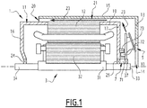
- the figure 1 illustrates an electric traction motor of a vehicle, that is to say a motor which operates, alone or in cooperation with other motors, the running of the vehicle.
- the vehicle concerned is preferably a rail vehicle, comprising one or more motors such as the one illustrated in figure 1 .
- the rail vehicle can be a train, such as a high speed train, or it can be a tram or a metro.
- the engine can be used for a non-rail vehicle, for example a road vehicle.
- the electric motor essentially comprises a stator 1, a rotor 3, a fan 5 and a magnetic reducer 7. On the figure 1 , these elements are partially represented.
- the motor defines a main axis X1, which is fixed relative to the stator 1.
- the stator 1 is a fixed part of the engine, which is intended to be attached to the chassis of the vehicle.
- the rotor 3 is designed to be mechanically linked to the wheels of the vehicle in order to drive their rotation for the purposes of rolling the vehicle.
- the stator 1 comprises a housing 11, through which the axis X1 passes, and a stator winding 12, received entirely inside the housing 11, and advantageously having an annular shape coaxial with the axis X1.
- the stator winding 12 here constitutes an inductor of the motor. It is through the housing 11 that the stator 1 is attached to the vehicle frame.
- the housing 11 comprises a rear wall 16, crossed by the axis X1.
- the wall 16 optionally comprises an opening centered on the axis X1.
- the housing 11 advantageously comprises a front wall 17, crossed by the axis X1 and having an opening centered on the axis X1.
- the housing 11 advantageously comprises a peripheral wall 19, of annular shape, coaxial with the axis X1, connecting the front wall 17 to the rear wall 16 to close the housing 11.
- the stator 1 preferably comprises a flange 13, arranged outside the housing 11, advantageously on the side of the front wall 17.
- the flange 13 has for example an annular shape coaxial with the axis X1, here a crown shape, of so as to provide an opening 14 for the circulation of ventilation air 23.
- the opening 14 is advantageously centered on, and traversed by, the axis X1.
- the stator 1 preferably comprises a skirt 15, of annular shape coaxial with the axis X1, which extends in the direction of the rear wall 16 from the flange 13.
- the flange 13 and, if provided, the skirt 15, are fixedly attached to the housing 11, while being kept at a distance from the walls 17 and 19, by any suitable means, including for example fixing lugs.
- An external wall of the stator 1, formed by the flange 13 and the skirt 15, and an internal wall of the stator 1, formed by the walls 17 and 19 of the housing 11, advantageously form a double skin and form an annular duct 21 between them, starting at the opening 14 and ending at an annular opening 20 formed at the opposite end of the skirt 15 around the wall 19.
- ventilation air circulates inside the annular duct 21 according to the arrows 23, from the opening 14 to the opening 20, to ventilate the motor, in particular to ventilate the contents of the housing 11, in particular the stator winding 12.
- the opening 14 is here an intake opening air
- the opening 20 is an air delivery opening.
- the rotor 3 is rotatable relative to the stator 1 around the axis X1.
- the rotor 3 comprises a rotor shaft 31, which is coaxial with the axis X1.
- the rotor 3 advantageously passes through the housing 11 along the axis X1, in that the rotor shaft 31 passes through the housing 11, passing through at least the opening formed by the wall 17.
- An axial end 33 of the shaft 31 therefore emerges out of the housing 11 through the wall 17.
- the end 33 does not extend beyond the flange 13.
- the shaft 31 also passes through the opening formed by the wall 16.
- An axial end 34 of the shaft 31 therefore emerges out of the housing 11 through the wall 16.
- the rotor shaft 31 is supported by the housing 11, so as to be rotatable relative to the housing 11 around the axis X1.
- the opening of the wall 17 comprises a bearing with rolling elements 25 centered on the axis X1.
- the shaft 31 also passes through the wall 16, in particular through the aforementioned opening of said wall 16, said opening then also comprising a rolling element bearing 24, centered on the axis X1.
- Each bearing 24 and 25 supports the shaft 31 relative to the housing 11 while allowing rotation about the axis X1. It is by means of the shaft 31 that the rotor actuates the rotation of the wheels of the vehicle.
- the rotor 3 comprises a rotor permanent magnet 32, a rotor winding, or a rotor cage, which is fixed with respect to the shaft 31 by being mounted around the shaft 31.
- the rotor permanent magnet 32, the rotor winding or the rotor cage constitutes the armature of the motor.
- the motor is preferably a permanent magnet motor, so that the rotor armature is a rotor permanent magnet.
- a permanent magnet synchronous motor is chosen.
- the armature 32 is disposed entirely inside the housing 11, being centered on the axis X1, and being radially surrounded by the stator winding 12.
- the winding stator 12 When supplying the motor with electrical energy, the winding stator 12 is supplied with electrical energy, which induces a rotation of the rotor armature 32, around the axis X1 with respect to the stator winding 12.
- the rotor armature 32 In the case where provision is made for the rotor armature 32 to be formed by a rotor winding, it may also be necessary to supply the rotor armature 32 with electrical energy so that the rotation is induced.
- an electrical power supply to the motor causes the rotor 3 to rotate relative to the stator 1 about the axis X1.
- the electric motor is designed so that, in nominal use of the motor, or for use of the motor at cruising speed, the rotor 3 is rotated at a speed w3 with respect to the stator 1 around the axis X1, which can be qualified as "nominal speed".
- the speed w3 is preferably equal to approximately 10,000 revolutions per minute. This speed w3 is achieved by supplying the motor with electrical energy, in steady state, under the traction load of the vehicle.
- the electric motor can be termed a high speed traction electric motor. More generally, it is expected that the speed w3 is greater than 5000 revolutions per minute, and is preferably greater than 9000 revolutions per minute.
- stator 1 and the rotor 3 are advantageously designed so that the motor has a power between 50kW and 2000kW, preferably between 100kW and 1000kW. Preferably, a power greater than 500kW is provided. This is the nominal mechanical power developed by the engine.
- the driving of the wheels of the vehicle by the motor for driving is advantageously carried out via the end 34, which is connected to said wheels by means of a mechanical transmission or any suitable means.
- the fan 5 forms a ventilation wheel, including for example blades.
- the fan 5 is preferably mounted on the end 33 of the shaft 31 by means of a bearing 37, preferably a rolling element bearing. Consequently, the fan 5 is rotatable with respect to the rotor 3 around the axis X1, and therefore, with respect to the stator 1.
- the fan 5 is preferably arranged between the flange 13 and the housing 11, in particular the wall. 17 of housing 11, as shown on figure 1 , so that the fan 5 is protected from the outside by the flange 13.
- the fan 5 When it is rotating relative to the stator 1, the fan 5 circulates the ventilation air according to the arrows 23. The rotation of the fan 5 therefore causes ventilation of the motor, in particular of the housing 11, for the purposes of its cooling.
- the ventilation air is drawn in axially by the fan 5 through the opening 14, the fan driving radially (with respect to the end 33 of the shaft 31) the air into the part of the duct 21 delimited by the wall 17 and the flange 13.
- the ventilation air is then guided in an axial direction, along the housing 11, by the part of the duct 21 which is delimited by the wall 19 and the skirt 15, until 'at opening 20.
- the rotor 3 when it rotates at the speed w3, drives the fan 5 in rotation around the axis X1 with respect to the stator 1 at a speed of rotation w5, by means of the magnetic reduction gear 7.
- the motor can therefore be qualified as "self-ventilated”.
- the reducer 7 is configured so that the fan 5 is rotated at a speed w5 lower than that of the rotor w3.
- the absolute value of the reduction ratio R is 0.5
- the fan 5 rotates half as fast as the rotor 3, according to the same direction of rotation or in the opposite direction, which considerably reduces the noise generated, while the speed w3 is greater than 5000 revolutions per minute, and especially if the speed w3 reaches 10,000 revolutions per minute.
- the magnetic reducer 7 advantageously comprises an inner ring 71, an intermediate ring 72 and a outer ring 73. These three rings 71, 72 and 73 are coaxial with the axis X1.
- the inner ring 71 is radially surrounded by the intermediate ring 72 and by the outer ring 73.
- the intermediate ring 72 radially surrounds the inner ring 71 and is radially surrounded by the outer ring 73.
- the outer ring 73 radially surrounds the inner ring 71 and the intermediate crown.
- the reducer 7 is arranged between the housing 11, in particular the wall 17, and the fan 5.
- the fan 5 covers the reducer 7 and protects it from the outside, in particular from any metal dust which could be carried by the ventilation air flow.
- the reducer 7 and the fan 5 are advantageously outside the housing 11, which facilitates their assembly and maintenance. Thanks to this particular arrangement, it is also easy to modify a pre-existing motor by adding the fan 5 and the reduction gear 7 to a free rotor shaft end.
- the inner ring 71 is fixed relative to the rotor 3, being here mounted by being fixed to the shaft 31.
- the ring 71 is fixed to the end 33, preferably between the bearings 25 and 37.
- the speed of rotation of the inner ring 71 is therefore equal to the speed w3.
- the inner ring 71 comprises a plurality of separate permanent magnets 74, which are regularly distributed around the main axis X1.
- the number of permanent magnets 74 and their arrangement defines a number of pairs of magnetic poles p1 of the inner ring 71.
- the magnets 74 are in even number and define an alternation of positive and negative poles around the axis X1, so that the number of pairs of poles p1 is equal to five.
- the outer ring 73 comprises a plurality of separate permanent magnets 76, which are regularly distributed around the main axis X1.
- the number of permanent magnets 76 and their arrangement defines a number of pairs of poles p3 of the outer ring 73.
- the magnets 76 are in even number and define an alternation of positive and negative poles around the axis X1, so that the number of pairs of poles p3 is equal to ten.
- the intermediate ring 72 which can be qualified as a “modulator”, which comprises a plurality of separate ferromagnetic parts 75, which are regularly distributed around the main axis X1.
- ferromagnetic is meant that the parts 75 have the ability to magnetize under the effect of a magnetic field exterior, here provided by the permanent magnets 74 and 76.
- the intermediate ring 72 comprises a number of ferromagnetic parts n2. On the figure 5 , the number of ferromagnetic parts 75 is equal to fourteen.
- the outer ring 73 constitutes a stator ring of the reduction gear 7, insofar as the outer ring 73 is fixed to the stator 1, in particular to the housing 11, here to the wall 17.
- the speed of rotation of the stator ring is zero.
- the intermediate ring gear 72 constitutes a driving ring, insofar as the intermediate ring 72 is fixed to the fan 5.
- the speed of rotation of the driving ring is equal to the speed w5.
- the numbers n2, p1 and p3 are therefore chosen so as to adapt the value of k, so as to obtain the desired reduction ratio R.
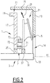
- the engine of the figure 2 differs from the engine of the figure 1 in that the intermediate ring 72 is fixed to the stator 1, in particular to the housing 11, here to the wall 17, so that the intermediate ring 72 constitutes the stator ring, and in that the outer ring 73 is fixed to the fan 5 and thus constitutes the driving crown.
- the reduction ratio R can be modified by inversion of the rings 72 and 73, that is to say by choosing which one, among the crowns 72 and 73, is respectively the driving crown or the stator crown.
- the engine of the figure 3 differs from the engine of the figure 1 in that the magnetic reducer 7 is axially disposed between the fan 5 and the flange 13.
- the outer ring 73 which constitutes the stator ring, is fixed to the stator 1 by means of the flange 13.
- the stator ring gear is fixed to the flange 13 by means of one or more fixing lug (s) 29.
- the inner ring gear 71 is fixed to the end 33 of the shaft, against the bearing 37 or near it, on the side. exterior of the fan 5. This arrangement of the magnetic reducer 7 makes it easier to maintain and install it, to the detriment of its protection from the outside.
- the invention applies to a closed self-ventilated motor, in particular insofar as the ventilation air 23 is circulated along the housing 11 containing the stator winding 12 and being traversed by the rotor 3, and not through inside the housing 11.
- the motor is an open motor, where the circulating air passes through the housing 11 and where, preferably, the fan 5 is. disposed inside the housing 11.
- the flange 13 and the skirt 15 are not necessary.
- stator to include the armature, while the rotor includes the inductor, the armature and the inductor being preferably contained inside the housing 11.
Landscapes
- Engineering & Computer Science (AREA)
- Power Engineering (AREA)
- Connection Of Motors, Electrical Generators, Mechanical Devices, And The Like (AREA)
- Motor Or Generator Cooling System (AREA)
- Electric Propulsion And Braking For Vehicles (AREA)
Applications Claiming Priority (1)
| Application Number | Priority Date | Filing Date | Title |
|---|---|---|---|
| FR1912346A FR3102896B1 (fr) | 2019-11-04 | 2019-11-04 | Moteur électrique de traction d’un véhicule |
Publications (3)
| Publication Number | Publication Date |
|---|---|
| EP3817201A1 true EP3817201A1 (de) | 2021-05-05 |
| EP3817201B1 EP3817201B1 (de) | 2024-04-17 |
| EP3817201C0 EP3817201C0 (de) | 2024-04-17 |
Family
ID=69811014
Family Applications (1)
| Application Number | Title | Priority Date | Filing Date |
|---|---|---|---|
| EP20205175.1A Active EP3817201B1 (de) | 2019-11-04 | 2020-11-02 | Elektrofahrmootor für ein fahrzeug |
Country Status (5)
| Country | Link |
|---|---|
| EP (1) | EP3817201B1 (de) |
| JP (1) | JP7666910B2 (de) |
| CN (1) | CN112787463B (de) |
| ES (1) | ES2992142T3 (de) |
| FR (1) | FR3102896B1 (de) |
Cited By (2)
| Publication number | Priority date | Publication date | Assignee | Title |
|---|---|---|---|---|
| CN113746271A (zh) * | 2021-08-26 | 2021-12-03 | 江苏航天动力机电有限公司 | 一种自热冷却的永磁电机 |
| EP4395144A1 (de) * | 2022-12-23 | 2024-07-03 | Black & Decker Inc. | Magnetgetriebe und elektrowerkzeug mit magnetgetriebe |
Citations (5)
| Publication number | Priority date | Publication date | Assignee | Title |
|---|---|---|---|---|
| WO1996037035A1 (de) * | 1995-05-16 | 1996-11-21 | Siemens Aktiengesellschaft | Elektromotorischer antrieb |
| EP0930692A2 (de) * | 1998-01-15 | 1999-07-21 | Siemens Aktiengesellschaft | Elektromotorischer Antrieb |
| US6661144B1 (en) * | 1999-01-27 | 2003-12-09 | Siemens Aktiengesellschaft | Electromotive drive |
| WO2012093670A1 (ja) * | 2011-01-07 | 2012-07-12 | 株式会社日立製作所 | 磁気ギヤ及びそれを有する回転機 |
| JP2013211949A (ja) * | 2012-03-30 | 2013-10-10 | Hitachi Industrial Equipment Systems Co Ltd | 電動機 |
Family Cites Families (6)
| Publication number | Priority date | Publication date | Assignee | Title |
|---|---|---|---|---|
| FR2979499B1 (fr) * | 2011-08-30 | 2013-09-20 | Leroy Somer Moteurs | Machine electrique a refroidissement ameliore. |
| JP2014079132A (ja) | 2012-10-12 | 2014-05-01 | Seiko Epson Corp | コアレス電気機械装置、コアレス電気機械装置の制御方法並びにコアレス電気機械装置を用いた移動体およびロボット |
| CN105006949B (zh) * | 2015-07-16 | 2017-05-24 | 江苏磁谷科技股份有限公司 | 一种电磁减速器 |
| EP3263418B1 (de) * | 2016-07-01 | 2021-01-13 | Západoceská Univerzita V Plzni | Kompaktantriebseinheit für zugfahrzeuge |
| JP7050534B2 (ja) | 2018-03-08 | 2022-04-08 | テルモ株式会社 | ポンプ装置 |
| CN110350758A (zh) * | 2019-07-31 | 2019-10-18 | 泰乐玛公司 | 电磁减速器和发电机组件以及包含该组件的车辆 |
-
2019
- 2019-11-04 FR FR1912346A patent/FR3102896B1/fr active Active
-
2020
- 2020-10-28 CN CN202011172166.3A patent/CN112787463B/zh active Active
- 2020-11-02 ES ES20205175T patent/ES2992142T3/es active Active
- 2020-11-02 EP EP20205175.1A patent/EP3817201B1/de active Active
- 2020-11-02 JP JP2020183548A patent/JP7666910B2/ja active Active
Patent Citations (5)
| Publication number | Priority date | Publication date | Assignee | Title |
|---|---|---|---|---|
| WO1996037035A1 (de) * | 1995-05-16 | 1996-11-21 | Siemens Aktiengesellschaft | Elektromotorischer antrieb |
| EP0930692A2 (de) * | 1998-01-15 | 1999-07-21 | Siemens Aktiengesellschaft | Elektromotorischer Antrieb |
| US6661144B1 (en) * | 1999-01-27 | 2003-12-09 | Siemens Aktiengesellschaft | Electromotive drive |
| WO2012093670A1 (ja) * | 2011-01-07 | 2012-07-12 | 株式会社日立製作所 | 磁気ギヤ及びそれを有する回転機 |
| JP2013211949A (ja) * | 2012-03-30 | 2013-10-10 | Hitachi Industrial Equipment Systems Co Ltd | 電動機 |
Non-Patent Citations (3)
| Title |
|---|
| A MATTHEE ET AL: "A high performance concentric magnetic gear", PROC. OF THE SOUTHERN AFRICAN UNIVERSITIES POWER ENGINEERING CONFERENCE, 1 January 2015 (2015-01-01), pages 203 - 207, XP055707161, DOI: 10.13140/RG.2.1.1493.6167 * |
| GERBER S ET AL: "Analysis of the end-effects in magnetic gears and magnetically geared machines", 2014 INTERNATIONAL CONFERENCE ON ELECTRICAL MACHINES (ICEM), IEEE, 2 September 2014 (2014-09-02), pages 396 - 402, XP032687640, DOI: 10.1109/ICELMACH.2014.6960211 * |
| NEVES CARLOS G C ET AL: "Magnetic gear: A review", 2014 11TH IEEE/IAS INTERNATIONAL CONFERENCE ON INDUSTRY APPLICATIONS, IEEE, 7 December 2014 (2014-12-07), pages 1 - 6, XP032746716, DOI: 10.1109/INDUSCON.2014.7059417 * |
Cited By (2)
| Publication number | Priority date | Publication date | Assignee | Title |
|---|---|---|---|---|
| CN113746271A (zh) * | 2021-08-26 | 2021-12-03 | 江苏航天动力机电有限公司 | 一种自热冷却的永磁电机 |
| EP4395144A1 (de) * | 2022-12-23 | 2024-07-03 | Black & Decker Inc. | Magnetgetriebe und elektrowerkzeug mit magnetgetriebe |
Also Published As
| Publication number | Publication date |
|---|---|
| FR3102896A1 (fr) | 2021-05-07 |
| JP7666910B2 (ja) | 2025-04-22 |
| JP2021078346A (ja) | 2021-05-20 |
| EP3817201B1 (de) | 2024-04-17 |
| EP3817201C0 (de) | 2024-04-17 |
| ES2992142T3 (es) | 2024-12-09 |
| CN112787463B (zh) | 2025-06-10 |
| FR3102896B1 (fr) | 2021-11-26 |
| CN112787463A (zh) | 2021-05-11 |
Similar Documents
| Publication | Publication Date | Title |
|---|---|---|
| EP3927621B1 (de) | Elektrische antriebseinheit für ein flugzeug und verfahren zur verwendung einer solchen antriebseinheit | |
| FR3056352B1 (fr) | Helice double flux pour machine electrique | |
| EP2561599B1 (de) | Rotor einer elektrischen drehmaschine mit interpolaren strukturen | |
| FR2494517A1 (fr) | Alternateur pour vehicule automobile comportant un inducteur rotatif porte par un arbre creux | |
| EP3817201B1 (de) | Elektrofahrmootor für ein fahrzeug | |
| EP2157679A1 (de) | Rotor einer synchron umlaufenden Elektromaschine, insbesondere Lichtmaschine für Kraftfahrzeug | |
| WO2017121930A1 (fr) | Machine electrique tournante à refroidissement amelioré | |
| EP2643918B1 (de) | Einteilige spannungsregler-/bürstenhalteranordnung für eine elektrische drehmaschine und elektrische drehmaschine mit einer derartigen anordnung | |
| CA3091871C (fr) | Turbopropulseur comprenant une generatrice d'electricite integree | |
| FR3057029A1 (fr) | Turbopropulseur comprenant une generatrice d'electricite integree | |
| FR2602925A1 (fr) | Dispositif interne de ventilation pour une machine electrique tournante telle qu'un alternateur | |
| WO2006117446A1 (fr) | Ventilateur debrayable pour un ralentisseur electromagnetique | |
| EP3382856A1 (de) | Elektrisch umlaufende maschine mit optimierter kühlung | |
| FR2811267A1 (fr) | Groupe motopropulseur pour vehicule a motorisation hybride avec deux machines electriques concentriques | |
| FR3098038A1 (fr) | Machine electrique tournante à configuration co-axiale | |
| WO2016189230A1 (fr) | Machine electrique tournante a circuit de refroidissement optimise | |
| FR3086128A1 (fr) | Machine electrique tournante munie d'au moins une gorge de reserve de lubrifiant | |
| EP2879274B1 (de) | Elektromaschine zum Antrieb eines elektrischen Kompressors und elektrischer Kompressor mit einer derartigen elektrischen Maschine | |
| FR2864367A1 (fr) | Dispositif de ventilation pour machine electrique tournante autour d'un arbre, a ventilateur independant de l'arbre | |
| FR3098055A1 (fr) | Machine electrique tournante munie d'ailettes de refroidissement | |
| FR3131124A1 (fr) | Stator de machine électrique tournante équipé d’un isolant d’un bobinage d’excitation | |
| FR3058366A1 (fr) | Interface mecanique entre une machine electrique tournante et une boite de vitesses | |
| WO2003026099A1 (fr) | Dispositif de ventilation pour machine electrique tournante et machine electrique pourvue d'un tel dispositif | |
| EP4357215A1 (de) | Selbstentlüftender motor, insbesondere für ein schienenfahrzeug, schienenfahrzeug mit einem solchen motor und montageverfahren dafür | |
| FR3098041A1 (fr) | Machine electrique tournante à refroidissement par huile |
Legal Events
| Date | Code | Title | Description |
|---|---|---|---|
| PUAI | Public reference made under article 153(3) epc to a published international application that has entered the european phase |
Free format text: ORIGINAL CODE: 0009012 |
|
| STAA | Information on the status of an ep patent application or granted ep patent |
Free format text: STATUS: THE APPLICATION HAS BEEN PUBLISHED |
|
| STAA | Information on the status of an ep patent application or granted ep patent |
Free format text: STATUS: REQUEST FOR EXAMINATION WAS MADE |
|
| AK | Designated contracting states |
Kind code of ref document: A1 Designated state(s): AL AT BE BG CH CY CZ DE DK EE ES FI FR GB GR HR HU IE IS IT LI LT LU LV MC MK MT NL NO PL PT RO RS SE SI SK SM TR |
|
| 17P | Request for examination filed |
Effective date: 20210419 |
|
| RBV | Designated contracting states (corrected) |
Designated state(s): AL AT BE BG CH CY CZ DE DK EE ES FI FR GB GR HR HU IE IS IT LI LT LU LV MC MK MT NL NO PL PT RO RS SE SI SK SM TR |
|
| STAA | Information on the status of an ep patent application or granted ep patent |
Free format text: STATUS: EXAMINATION IS IN PROGRESS |
|
| 17Q | First examination report despatched |
Effective date: 20230227 |
|
| P01 | Opt-out of the competence of the unified patent court (upc) registered |
Effective date: 20230823 |
|
| RAP1 | Party data changed (applicant data changed or rights of an application transferred) |
Owner name: ALSTOM HOLDINGS |
|
| GRAP | Despatch of communication of intention to grant a patent |
Free format text: ORIGINAL CODE: EPIDOSNIGR1 |
|
| STAA | Information on the status of an ep patent application or granted ep patent |
Free format text: STATUS: GRANT OF PATENT IS INTENDED |
|
| INTG | Intention to grant announced |
Effective date: 20231115 |
|
| GRAS | Grant fee paid |
Free format text: ORIGINAL CODE: EPIDOSNIGR3 |
|
| GRAA | (expected) grant |
Free format text: ORIGINAL CODE: 0009210 |
|
| STAA | Information on the status of an ep patent application or granted ep patent |
Free format text: STATUS: THE PATENT HAS BEEN GRANTED |
|
| AK | Designated contracting states |
Kind code of ref document: B1 Designated state(s): AL AT BE BG CH CY CZ DE DK EE ES FI FR GB GR HR HU IE IS IT LI LT LU LV MC MK MT NL NO PL PT RO RS SE SI SK SM TR |
|
| REG | Reference to a national code |
Ref country code: GB Ref legal event code: FG4D Free format text: NOT ENGLISH |
|
| REG | Reference to a national code |
Ref country code: CH Ref legal event code: EP |
|
| REG | Reference to a national code |
Ref country code: DE Ref legal event code: R096 Ref document number: 602020029071 Country of ref document: DE |
|
| REG | Reference to a national code |
Ref country code: IE Ref legal event code: FG4D Free format text: LANGUAGE OF EP DOCUMENT: FRENCH |
|
| U01 | Request for unitary effect filed |
Effective date: 20240517 |
|
| P04 | Withdrawal of opt-out of the competence of the unified patent court (upc) registered |
Effective date: 20240529 |
|
| U07 | Unitary effect registered |
Designated state(s): AT BE BG DE DK EE FI FR IT LT LU LV MT NL PT SE SI Effective date: 20240603 |
|
| PG25 | Lapsed in a contracting state [announced via postgrant information from national office to epo] |
Ref country code: IS Free format text: LAPSE BECAUSE OF FAILURE TO SUBMIT A TRANSLATION OF THE DESCRIPTION OR TO PAY THE FEE WITHIN THE PRESCRIBED TIME-LIMIT Effective date: 20240817 |
|
| PG25 | Lapsed in a contracting state [announced via postgrant information from national office to epo] |
Ref country code: HR Free format text: LAPSE BECAUSE OF FAILURE TO SUBMIT A TRANSLATION OF THE DESCRIPTION OR TO PAY THE FEE WITHIN THE PRESCRIBED TIME-LIMIT Effective date: 20240417 |
|
| PG25 | Lapsed in a contracting state [announced via postgrant information from national office to epo] |
Ref country code: GR Free format text: LAPSE BECAUSE OF FAILURE TO SUBMIT A TRANSLATION OF THE DESCRIPTION OR TO PAY THE FEE WITHIN THE PRESCRIBED TIME-LIMIT Effective date: 20240718 |
|
| PG25 | Lapsed in a contracting state [announced via postgrant information from national office to epo] |
Ref country code: PL Free format text: LAPSE BECAUSE OF FAILURE TO SUBMIT A TRANSLATION OF THE DESCRIPTION OR TO PAY THE FEE WITHIN THE PRESCRIBED TIME-LIMIT Effective date: 20240417 |
|
| PG25 | Lapsed in a contracting state [announced via postgrant information from national office to epo] |
Ref country code: PL Free format text: LAPSE BECAUSE OF FAILURE TO SUBMIT A TRANSLATION OF THE DESCRIPTION OR TO PAY THE FEE WITHIN THE PRESCRIBED TIME-LIMIT Effective date: 20240417 Ref country code: NO Free format text: LAPSE BECAUSE OF FAILURE TO SUBMIT A TRANSLATION OF THE DESCRIPTION OR TO PAY THE FEE WITHIN THE PRESCRIBED TIME-LIMIT Effective date: 20240717 Ref country code: IS Free format text: LAPSE BECAUSE OF FAILURE TO SUBMIT A TRANSLATION OF THE DESCRIPTION OR TO PAY THE FEE WITHIN THE PRESCRIBED TIME-LIMIT Effective date: 20240817 Ref country code: HR Free format text: LAPSE BECAUSE OF FAILURE TO SUBMIT A TRANSLATION OF THE DESCRIPTION OR TO PAY THE FEE WITHIN THE PRESCRIBED TIME-LIMIT Effective date: 20240417 Ref country code: GR Free format text: LAPSE BECAUSE OF FAILURE TO SUBMIT A TRANSLATION OF THE DESCRIPTION OR TO PAY THE FEE WITHIN THE PRESCRIBED TIME-LIMIT Effective date: 20240718 Ref country code: RS Free format text: LAPSE BECAUSE OF FAILURE TO SUBMIT A TRANSLATION OF THE DESCRIPTION OR TO PAY THE FEE WITHIN THE PRESCRIBED TIME-LIMIT Effective date: 20240717 |
|
| REG | Reference to a national code |
Ref country code: ES Ref legal event code: FG2A Ref document number: 2992142 Country of ref document: ES Kind code of ref document: T3 Effective date: 20241209 |
|
| U20 | Renewal fee for the european patent with unitary effect paid |
Year of fee payment: 5 Effective date: 20241126 |
|
| P05 | Withdrawal of opt-out of the competence of the unified patent court (upc) changed |
Free format text: CASE NUMBER: APP_31949/2024 Effective date: 20240603 |
|
| REG | Reference to a national code |
Ref country code: DE Ref legal event code: R097 Ref document number: 602020029071 Country of ref document: DE |
|
| PG25 | Lapsed in a contracting state [announced via postgrant information from national office to epo] |
Ref country code: SK Free format text: LAPSE BECAUSE OF FAILURE TO SUBMIT A TRANSLATION OF THE DESCRIPTION OR TO PAY THE FEE WITHIN THE PRESCRIBED TIME-LIMIT Effective date: 20240417 Ref country code: RO Free format text: LAPSE BECAUSE OF FAILURE TO SUBMIT A TRANSLATION OF THE DESCRIPTION OR TO PAY THE FEE WITHIN THE PRESCRIBED TIME-LIMIT Effective date: 20240417 |
|
| PG25 | Lapsed in a contracting state [announced via postgrant information from national office to epo] |
Ref country code: SM Free format text: LAPSE BECAUSE OF FAILURE TO SUBMIT A TRANSLATION OF THE DESCRIPTION OR TO PAY THE FEE WITHIN THE PRESCRIBED TIME-LIMIT Effective date: 20240417 |
|
| PG25 | Lapsed in a contracting state [announced via postgrant information from national office to epo] |
Ref country code: SM Free format text: LAPSE BECAUSE OF FAILURE TO SUBMIT A TRANSLATION OF THE DESCRIPTION OR TO PAY THE FEE WITHIN THE PRESCRIBED TIME-LIMIT Effective date: 20240417 Ref country code: SK Free format text: LAPSE BECAUSE OF FAILURE TO SUBMIT A TRANSLATION OF THE DESCRIPTION OR TO PAY THE FEE WITHIN THE PRESCRIBED TIME-LIMIT Effective date: 20240417 Ref country code: RO Free format text: LAPSE BECAUSE OF FAILURE TO SUBMIT A TRANSLATION OF THE DESCRIPTION OR TO PAY THE FEE WITHIN THE PRESCRIBED TIME-LIMIT Effective date: 20240417 |
|
| PLBE | No opposition filed within time limit |
Free format text: ORIGINAL CODE: 0009261 |
|
| STAA | Information on the status of an ep patent application or granted ep patent |
Free format text: STATUS: NO OPPOSITION FILED WITHIN TIME LIMIT |
|
| 26N | No opposition filed |
Effective date: 20250120 |
|
| REG | Reference to a national code |
Ref country code: CH Ref legal event code: PL |
|
| PG25 | Lapsed in a contracting state [announced via postgrant information from national office to epo] |
Ref country code: MC Free format text: LAPSE BECAUSE OF FAILURE TO SUBMIT A TRANSLATION OF THE DESCRIPTION OR TO PAY THE FEE WITHIN THE PRESCRIBED TIME-LIMIT Effective date: 20240417 |
|
| REG | Reference to a national code |
Ref country code: CH Ref legal event code: PL |
|
| GBPC | Gb: european patent ceased through non-payment of renewal fee |
Effective date: 20241102 |
|
| PG25 | Lapsed in a contracting state [announced via postgrant information from national office to epo] |
Ref country code: CH Free format text: LAPSE BECAUSE OF NON-PAYMENT OF DUE FEES Effective date: 20241130 |
|
| PG25 | Lapsed in a contracting state [announced via postgrant information from national office to epo] |
Ref country code: GB Free format text: LAPSE BECAUSE OF NON-PAYMENT OF DUE FEES Effective date: 20241102 |
|
| PG25 | Lapsed in a contracting state [announced via postgrant information from national office to epo] |
Ref country code: IE Free format text: LAPSE BECAUSE OF NON-PAYMENT OF DUE FEES Effective date: 20241102 |
|
| U20 | Renewal fee for the european patent with unitary effect paid |
Year of fee payment: 6 Effective date: 20251127 |
|
| PGFP | Annual fee paid to national office [announced via postgrant information from national office to epo] |
Ref country code: CZ Payment date: 20251029 Year of fee payment: 6 |
|
| PGFP | Annual fee paid to national office [announced via postgrant information from national office to epo] |
Ref country code: ES Payment date: 20251229 Year of fee payment: 6 |
|
| PG25 | Lapsed in a contracting state [announced via postgrant information from national office to epo] |
Ref country code: HU Free format text: LAPSE BECAUSE OF FAILURE TO SUBMIT A TRANSLATION OF THE DESCRIPTION OR TO PAY THE FEE WITHIN THE PRESCRIBED TIME-LIMIT; INVALID AB INITIO Effective date: 20201102 |
|
| PG25 | Lapsed in a contracting state [announced via postgrant information from national office to epo] |
Ref country code: CY Free format text: LAPSE BECAUSE OF FAILURE TO SUBMIT A TRANSLATION OF THE DESCRIPTION OR TO PAY THE FEE WITHIN THE PRESCRIBED TIME-LIMIT; INVALID AB INITIO Effective date: 20201102 |