EP3817400B1 - Hörvorrichtung, einen verbinder und ein verriegelungselement umfassend - Google Patents
Hörvorrichtung, einen verbinder und ein verriegelungselement umfassend Download PDFInfo
- Publication number
- EP3817400B1 EP3817400B1 EP19205701.6A EP19205701A EP3817400B1 EP 3817400 B1 EP3817400 B1 EP 3817400B1 EP 19205701 A EP19205701 A EP 19205701A EP 3817400 B1 EP3817400 B1 EP 3817400B1
- Authority
- EP
- European Patent Office
- Prior art keywords
- housing
- locking element
- connector
- state
- hearing device
- Prior art date
- Legal status (The legal status is an assumption and is not a legal conclusion. Google has not performed a legal analysis and makes no representation as to the accuracy of the status listed.)
- Active
Links
Images




Classifications
-
- H—ELECTRICITY
- H04—ELECTRIC COMMUNICATION TECHNIQUE
- H04R—LOUDSPEAKERS, MICROPHONES, GRAMOPHONE PICK-UPS OR LIKE ACOUSTIC ELECTROMECHANICAL TRANSDUCERS; ELECTRIC HEARING AIDS; PUBLIC ADDRESS SYSTEMS
- H04R25/00—Electric hearing aids
- H04R25/60—Mounting or interconnection of hearing aid parts, e.g. inside tips, housings or to ossicles
-
- H—ELECTRICITY
- H04—ELECTRIC COMMUNICATION TECHNIQUE
- H04R—LOUDSPEAKERS, MICROPHONES, GRAMOPHONE PICK-UPS OR LIKE ACOUSTIC ELECTROMECHANICAL TRANSDUCERS; ELECTRIC HEARING AIDS; PUBLIC ADDRESS SYSTEMS
- H04R25/00—Electric hearing aids
- H04R25/55—Electric hearing aids using an external connection, either wireless or wired
- H04R25/556—External connectors, e.g. plugs or modules
-
- H—ELECTRICITY
- H04—ELECTRIC COMMUNICATION TECHNIQUE
- H04R—LOUDSPEAKERS, MICROPHONES, GRAMOPHONE PICK-UPS OR LIKE ACOUSTIC ELECTROMECHANICAL TRANSDUCERS; ELECTRIC HEARING AIDS; PUBLIC ADDRESS SYSTEMS
- H04R1/00—Details of transducers, loudspeakers or microphones
- H04R1/10—Earpieces; Attachments therefor ; Earphones; Monophonic headphones
- H04R1/1016—Earpieces of the intra-aural type
-
- H—ELECTRICITY
- H04—ELECTRIC COMMUNICATION TECHNIQUE
- H04R—LOUDSPEAKERS, MICROPHONES, GRAMOPHONE PICK-UPS OR LIKE ACOUSTIC ELECTROMECHANICAL TRANSDUCERS; ELECTRIC HEARING AIDS; PUBLIC ADDRESS SYSTEMS
- H04R1/00—Details of transducers, loudspeakers or microphones
- H04R1/10—Earpieces; Attachments therefor ; Earphones; Monophonic headphones
- H04R1/1058—Manufacture or assembly
-
- H—ELECTRICITY
- H04—ELECTRIC COMMUNICATION TECHNIQUE
- H04R—LOUDSPEAKERS, MICROPHONES, GRAMOPHONE PICK-UPS OR LIKE ACOUSTIC ELECTROMECHANICAL TRANSDUCERS; ELECTRIC HEARING AIDS; PUBLIC ADDRESS SYSTEMS
- H04R25/00—Electric hearing aids
- H04R25/65—Housing parts, e.g. shells, tips or moulds, or their manufacture
-
- H—ELECTRICITY
- H01—ELECTRIC ELEMENTS
- H01R—ELECTRICALLY-CONDUCTIVE CONNECTIONS; STRUCTURAL ASSOCIATIONS OF A PLURALITY OF MUTUALLY-INSULATED ELECTRICAL CONNECTING ELEMENTS; COUPLING DEVICES; CURRENT COLLECTORS
- H01R13/00—Details of coupling devices of the kinds covered by groups H01R12/70 or H01R24/00 - H01R33/00
- H01R13/62—Means for facilitating engagement or disengagement of coupling parts or for holding them in engagement
- H01R13/639—Additional means for holding or locking coupling parts together, after engagement, e.g. separate keylock, retainer strap
- H01R13/6395—Additional means for holding or locking coupling parts together, after engagement, e.g. separate keylock, retainer strap for wall or panel outlets
-
- H—ELECTRICITY
- H04—ELECTRIC COMMUNICATION TECHNIQUE
- H04R—LOUDSPEAKERS, MICROPHONES, GRAMOPHONE PICK-UPS OR LIKE ACOUSTIC ELECTROMECHANICAL TRANSDUCERS; ELECTRIC HEARING AIDS; PUBLIC ADDRESS SYSTEMS
- H04R2225/00—Details of deaf aids covered by H04R25/00, not provided for in any of its subgroups
- H04R2225/021—Behind the ear [BTE] hearing aids
-
- H—ELECTRICITY
- H04—ELECTRIC COMMUNICATION TECHNIQUE
- H04R—LOUDSPEAKERS, MICROPHONES, GRAMOPHONE PICK-UPS OR LIKE ACOUSTIC ELECTROMECHANICAL TRANSDUCERS; ELECTRIC HEARING AIDS; PUBLIC ADDRESS SYSTEMS
- H04R2225/00—Details of deaf aids covered by H04R25/00, not provided for in any of its subgroups
- H04R2225/021—Behind the ear [BTE] hearing aids
- H04R2225/0213—Constructional details of earhooks, e.g. shape, material
-
- H—ELECTRICITY
- H04—ELECTRIC COMMUNICATION TECHNIQUE
- H04R—LOUDSPEAKERS, MICROPHONES, GRAMOPHONE PICK-UPS OR LIKE ACOUSTIC ELECTROMECHANICAL TRANSDUCERS; ELECTRIC HEARING AIDS; PUBLIC ADDRESS SYSTEMS
- H04R2225/00—Details of deaf aids covered by H04R25/00, not provided for in any of its subgroups
- H04R2225/025—In the ear hearing aids [ITE] hearing aids
-
- H—ELECTRICITY
- H04—ELECTRIC COMMUNICATION TECHNIQUE
- H04R—LOUDSPEAKERS, MICROPHONES, GRAMOPHONE PICK-UPS OR LIKE ACOUSTIC ELECTROMECHANICAL TRANSDUCERS; ELECTRIC HEARING AIDS; PUBLIC ADDRESS SYSTEMS
- H04R2225/00—Details of deaf aids covered by H04R25/00, not provided for in any of its subgroups
- H04R2225/57—Aspects of electrical interconnection between hearing aid parts
Definitions
- the present invention relates to a hearing device. More specifically, the disclosure relates to a hearing device comprising a behind-the-ear housing, a connector configured for connecting the housing to an element, and a locking element.
- the locking element is configured for locking the connector to the housing.
- a hearing device which comprises different parts
- a locking mechanism on a hearing device may also be small and delicate with a risk of easily breaking.
- due to the small size it is a problem that locking mechanisms tend to require the use of tools, which may make the locking mechanism difficult and cumbersome for a user to operate.
- EP 3 503 587 A1 shows a hearing aid comprising a hearing aid housing with a connector socket and an earpiece connector with a connector plug, and where the connector socket and the connector plug are configured such that the connector plug is releasably attached in the connector socket for connecting the connector to the hearing aid housing.
- the connector plug comprises a connector plug body having a separate deadbolt movably arranged in the connector plug body.
- the connector may be removably attached to the housing, since this provides that the connector may deliberately or intentionally be removed from the housing.
- the connector is configured for connecting the housing to an element.
- the connector may be connected or attached to the element.
- a particular connector and/or element connected to the connector may be replaced by a different connector and/or element, such that for example a user may change, attach, or detach the connector and/or element for e.g. replacing the connector and/or element or for cleaning the connector and/or element.
- the connector comprises a first electronic connection element and a second electronic connection element.
- the first electronic connection element is configured to be arranged in a depression in the bottom part of the housing.
- the primary part is configured to be arranged in the guide, since this provides that the guide may guide or lead or facilitate movement or displacement or direction of the primary part of the connector within the locking element during insertion and/or removal of the connector into the housing.
- the locking element may be configured to be arranged in the bottom part of the housing.
- moving the locking element in a direction parallel to the longitudinal direction of the housing may comprise moving the locking element in a direction parallel to the surface of the bottom part of the housing.
- the locking element comprises a first side and a second side, wherein the first side is opposite the second side, and the first side comprises the guide, and the second side comprises a protrusion which is configured to slide between a first position and a second position, the first position corresponds to the first state of the locking element and the second position corresponds to the second state of the locking element.
- the protrusion may comprise a latch.
- the protrusion may be configured to slide between the first and the second position in a corresponding lane or track or trail comprised in the housing.
- the track may be arranged on a side of the locking element other than the first side and other than the second side.
- the track may be arranged on a third and/a fourth side of the locking element, the third and fourth side of the locking element may be provided opposite each other.
- the housing may comprise a part that corresponds to the track in the locking element, thus the housing may comprise a rail that is provided or arranged or accommodated in the track of the locking element.
- the track may comprise an indentation in the locking element, while the rail may comprise a protrusion in the housing.
- the track provides that the locking element is guided when the locking element moves between the first and second positions.
- the track and/or corresponding rail may guide the movement of the locking element.
- a robust lock such as a robust mechanical lock is provided.
- the connector may comprise a member or stop means which functions to prevent pull forces from opening the lock or locking element, e.g. to prevent unintentional detachment of the connector from the housing.
- the member may be provided at the interface of the first electronic connection element and the second electronic connection element.
- the member may be a part of the first electronic connection element and the member may protrude from the first electronic connection element.
- the member When the connector is inserted in the housing, the member may be provided in a corresponding indentation of the rail provided in the housing.
- pull force in the connector in the longitudinal direction of the housing may be obtained in the bottom of the housing.
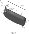
- Fig. 1a , 1b and 1c schematically illustrate an exemplary hearing device 2.
- the hearing device 2 comprises a behind-the-ear housing 4.
- the housing 4 comprises a bottom part 6, a top part 8 opposite the bottom part 6, a front part 10, and a rear part 12 opposite the front part 10.
- the hearing device 2 comprises a connector 14.
- the connector 14 is configured to be removably attached to the housing 4.
- the connector 14 is configured for connecting the housing 4 to an element 16, as shown in Fig. 1c .
- the element 16 is being configured to be arranged in or at the ear of the user.
- the housing 4 comprises a locking element 18.
- the locking element 18 is configured for locking the connector 14 to/in the housing 4.
- the housing 4 comprises a guide 20 for at least a part of the connector 14.
- the guide 20 is provided in the locking element 18.
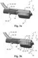
- the connector 14 is configured to be arranged in the bottom part 6 of the housing 4.
- Fig. 8 schematically illustrates an exemplary hearing device.
- Fig. 8 shows that the connector 14 is configured to be removably attached to the housing 4.
- Fig. 8 shows the connector 14 being removed, detached or being outside from the housing 4.
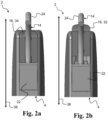
- the connector comprises the first electronic connection element 22 and the second electronic connection element 24.
- the second electronic connection element 24 comprises the primary part 26 and the secondary part 28. See Fig. 4 for an illustration of that the primary part 26 is configured for being provided inside the housing 4 when the connector 14 is arranged in the housing 4, and that the secondary part 28 is configured for extending from the housing 4 when the connector 14 is arranged in the housing 4.
Landscapes
- Engineering & Computer Science (AREA)
- Physics & Mathematics (AREA)
- Acoustics & Sound (AREA)
- Signal Processing (AREA)
- Health & Medical Sciences (AREA)
- General Health & Medical Sciences (AREA)
- Neurosurgery (AREA)
- Otolaryngology (AREA)
- Manufacturing & Machinery (AREA)
- Computer Networks & Wireless Communication (AREA)
- Details Of Connecting Devices For Male And Female Coupling (AREA)
Claims (12)
- Ein Hörgerät (2), umfassend:- ein Hinter-dem-Ohr-Gehäuse (4), wobei das Gehäuse aus einem Unterteil (6), einem dem Unterteil (6) gegenüberliegenden Oberteil (8), einem Vorderteil (10) und einem dem Vorderteil (10) gegenüberliegenden Hinterteil (12) besteht,- einen Verbinder (14), wobei der Verbinder (14) dazu konfiguriert ist, abnehmbar an dem Gehäuse (4) befestigt zu werden, wobei der Verbinder (14) dazu konfiguriert ist, das Gehäuse (4) mit einem Element (16) zu verbinden, wobei das Element (16) dazu konfiguriert ist, im oder am Ohr eines Benutzers angeordnet zu werden,wobei das Gehäuse (4) ein Verriegelungselement (18) umfasst, wobei das Verriegelungselement (18) zum Verriegeln des Verbinders (14) am/im Gehäuse (4) ausgebildet ist, und wobei das Gehäuse (4) eine Führung (20) für zumindest einen Teil des Verbinders (14) umfasst,wobei das Verriegelungselement (18) dazu konfiguriert ist, zwischen einem ersten Zustand (32) und einem zweiten Zustand (34) zu wechseln, wobei der erste Zustand (32) ein geöffneter Zustand ist, in dem das Verriegelungselement (18) dafür konfiguriert ist, dass der Verbinder (14) im Unterteil (6) des Gehäuses (4) angeordnet oder daraus entfernt werden kann, und wobei der zweite Zustand (34) ein verriegelter Zustand ist, in dem das Verriegelungselement (18) dafür konfiguriert ist, dass der Verbinder (14) nicht im Unterteil (6) des Gehäuses (4) angeordnet oder daraus entfernt werden kann,wobei das Hörgerät dadurch gekennzeichnet ist, dassdas Verriegelungselement (18) eine Schiene (56) zum Führen des Verriegelungselements (18) innerhalb des Gehäuses (4) umfasst, während das Verriegelungselement (18) zwischen dem ersten Zustand (32) und dem zweiten Zustand (34) wechselt.
- Hörgerät (2) nach Anspruch 1, wobei die Führung (20) im Verriegelungselement (18) vorgesehen ist.
- Hörgerät (2) nach einem der vorhergehenden Ansprüche, wobei der Verbinder (14) zur Anordnung im Unterteil (6) des Gehäuses (4) ausgebildet ist.
- Hörgerät (2) nach dem vorhergehenden Anspruch, wobei der Verbinder (14) ein erstes elektronisches Verbindungselement (22) und ein zweites elektronisches Verbindungselement (24) umfasst, wobei das erste elektronische Verbindungselement (22) dazu ausgebildet ist, in einer Vertiefung (30) im Unterteil (6) des Gehäuses (4) angeordnet zu werden.
- Hörgerät (2) nach Anspruch 4, wobei das zweite elektronische Verbindungselement (24) des Verbinders (14) einen Primärteil (26) und einen Sekundärteil (28) umfasst, wobei der Primärteil (26) dazu ausgebildet ist, in der Führung (20) angeordnet zu werden, und wobei der Sekundärteil (28) dazu ausgebildet ist, aus dem Gehäuse (4) herauszuragen.
- Hörgerät (2) nach Anspruch 1, wobei das Verriegelungselement (18) dazu konfiguriert ist, zwischen dem ersten Zustand (32) und dem zweiten Zustand (34) zu wechseln, indem das Verriegelungselement (18) in eine Richtung parallel zu einer Längsrichtung (36) des Gehäuses (4) bewegt wird, wobei die Längsrichtung (36) des Gehäuses (4) vom vorderen Teil des Gehäuses (4) zum hinteren Teil des Gehäuses (4) verläuft.
- Hörgerät (2) nach Anspruch 6, wobei das Bewegen des Verriegelungselements (18) in eine Richtung parallel zu einer Längsrichtung (36) des Gehäuses (4) das Bewegen des Verriegelungselements (18) in eine Richtung parallel zu einer Oberfläche des Teils des Gehäuses (4) umfasst, in dem sich das Verriegelungselement befindet.
- Hörgerät (2) nach einem der Ansprüche 1, 6 oder 7, wobei im ersten Zustand (32) des Verriegelungselements (18) zumindest ein Teil des Verriegelungselements (18) aus dem Gehäuse (4) hervorsteht und im zweiten Zustand (34) des Verriegelungselements (18) bündig/fluchtend mit dem Bodenteil (6) des Gehäuses (4) abschließt.
- Hörgerät (2) nach Anspruch 5, wobei die Führung (20) im Verriegelungselement (18) vorgesehen ist und einen Kanal (38) zur Aufnahme des Primärteils (26) des zweiten elektronischen Verbindungselement (24) des Verbinders (14) umfasst, und wobei das Verriegelungselement (18) dazu ausgebildet ist, zwischen dem ersten Zustand (32) und dem zweiten Zustand (34) zu wechseln, während das Primärteil (26) des zweiten elektronischen Verbindungselement (24) des Verbinders (14) im Kanal (38) aufgenommen ist.
- Hörgerät (2) nach Anspruch 4, wobei der Verbinder (14) dazu ausgebildet ist, im Unterteil (6) des Gehäuses (4) angeordnet zu werden, indem das erste elektronische Verbindungselement (22) des Verbinders (14) in die Vertiefung (30) im Unterteil (6) des Gehäuses (4) eingesetzt wird, wobei die Richtung des Einsetzens in einem Winkel (40) zwischen 10-80 Grad relativ zur Längsrichtung (36) des Gehäuses (4) liegt.
- Hörgerät (2) nach Anspruch 4, wobei das erste elektronische Verbindungselement (22) des Verbinders (14) eine dem Verriegelungselement (18) zugewandte schräge Ebene (42) aufweist, wodurch zwischen dem Verriegelungselement (18) und dem ersten elektronischen Verbindungselement (22) des Verbinders (14) eine Nut (44) gebildet ist, wenn sich das Verriegelungselement (18) im zweiten Zustand (34) befindet.
- Ein Hörgerät (2) nach Anspruch 1, wobei das Verriegelungselement (18) eine erste Seite (46) und eine zweite Seite (48) umfasst, wobei die erste Seite (46) der zweiten Seite (48) gegenüberliegt und die erste Seite (46) die Führung (20) umfasst und die zweite Seite (48) einen Vorsprung (50) umfasst, der so konfiguriert ist, dass er zwischen einer ersten Position (52) und einer zweiten Position (54) gleitet, wobei die erste Position (52) dem ersten Zustand (32) des Verriegelungselements (18) entspricht und die zweite Position (54) dem zweiten Zustand (34) des Verriegelungselements (18) entspricht.
Priority Applications (6)
| Application Number | Priority Date | Filing Date | Title |
|---|---|---|---|
| EP19205701.6A EP3817400B1 (de) | 2019-10-28 | 2019-10-28 | Hörvorrichtung, einen verbinder und ein verriegelungselement umfassend |
| EP24215096.9A EP4489443A1 (de) | 2019-10-28 | 2019-10-28 | Hörgerät mit einem verbinder und einem verriegelungselement |
| PCT/EP2020/079578 WO2021083756A1 (en) | 2019-10-28 | 2020-10-21 | A hearing device comprising a connector and a locking element |
| JP2022524287A JP2022554228A (ja) | 2019-10-28 | 2020-10-21 | コネクタ及びロッキング要素を備える聴覚装置 |
| CN202080075213.4A CN114642005B (zh) | 2019-10-28 | 2020-10-21 | 包含连接器和锁定元件的听力装置 |
| US17/702,727 US12089007B2 (en) | 2019-10-28 | 2022-03-23 | Hearing device comprising a connector and a locking element |
Applications Claiming Priority (1)
| Application Number | Priority Date | Filing Date | Title |
|---|---|---|---|
| EP19205701.6A EP3817400B1 (de) | 2019-10-28 | 2019-10-28 | Hörvorrichtung, einen verbinder und ein verriegelungselement umfassend |
Related Child Applications (2)
| Application Number | Title | Priority Date | Filing Date |
|---|---|---|---|
| EP24215096.9A Division-Into EP4489443A1 (de) | 2019-10-28 | 2019-10-28 | Hörgerät mit einem verbinder und einem verriegelungselement |
| EP24215096.9A Division EP4489443A1 (de) | 2019-10-28 | 2019-10-28 | Hörgerät mit einem verbinder und einem verriegelungselement |
Publications (3)
| Publication Number | Publication Date |
|---|---|
| EP3817400A1 EP3817400A1 (de) | 2021-05-05 |
| EP3817400B1 true EP3817400B1 (de) | 2025-07-02 |
| EP3817400C0 EP3817400C0 (de) | 2025-07-02 |
Family
ID=68382348
Family Applications (2)
| Application Number | Title | Priority Date | Filing Date |
|---|---|---|---|
| EP19205701.6A Active EP3817400B1 (de) | 2019-10-28 | 2019-10-28 | Hörvorrichtung, einen verbinder und ein verriegelungselement umfassend |
| EP24215096.9A Pending EP4489443A1 (de) | 2019-10-28 | 2019-10-28 | Hörgerät mit einem verbinder und einem verriegelungselement |
Family Applications After (1)
| Application Number | Title | Priority Date | Filing Date |
|---|---|---|---|
| EP24215096.9A Pending EP4489443A1 (de) | 2019-10-28 | 2019-10-28 | Hörgerät mit einem verbinder und einem verriegelungselement |
Country Status (5)
| Country | Link |
|---|---|
| US (1) | US12089007B2 (de) |
| EP (2) | EP3817400B1 (de) |
| JP (1) | JP2022554228A (de) |
| CN (1) | CN114642005B (de) |
| WO (1) | WO2021083756A1 (de) |
Family Cites Families (15)
| Publication number | Priority date | Publication date | Assignee | Title |
|---|---|---|---|---|
| DK2033487T3 (da) * | 2006-06-23 | 2013-05-27 | Gn Resound As | Høreapparat med et forlænget element |
| US8452021B2 (en) * | 2007-04-17 | 2013-05-28 | Starkey Laboratories, Inc. | Real ear measurement system using thin tube |
| EP2540098B1 (de) * | 2010-02-22 | 2018-09-12 | Sivantos Pte. Ltd. | Konnektor für ric-bte hörgerät und ric-bte hörgerät |
| US8638965B2 (en) * | 2010-07-14 | 2014-01-28 | Starkey Laboratories, Inc. | Receiver-in-canal hearing device cable connections |
| DE102010040834A1 (de) * | 2010-09-15 | 2012-03-15 | Siemens Medical Instruments Pte. Ltd. | Konnektor für Hörinstrument, Hörinstrument und Hörinstrumentensystem |
| DE102010051626B4 (de) * | 2010-11-17 | 2015-07-09 | Yamaichi Electronics Deutschland Gmbh | Hörgerät, Verbinder, Verwendung eines Verbinders und System zum Verbinden eines Hörgeräts mit einem Kabel |
| DK2680611T3 (da) * | 2012-06-27 | 2016-10-24 | Sivantos Pte Ltd | Hybrid høreinstrument-konnektor |
| DE202013000547U1 (de) * | 2013-01-18 | 2013-02-25 | Siemens Medical Instruments Pte. Ltd. | Hörinstrumentgehäuse mit Steckverbindung |
| DE102014200917A1 (de) * | 2014-01-20 | 2015-07-23 | Siemens Medical Instruments Pte. Ltd. | HdO-Hörinstrument mit Gehäuse und Schallschlauch |
| US10187735B2 (en) * | 2015-01-30 | 2019-01-22 | Gn Hearing A/S | Hearing aid device frame structure and locking plug |
| DE102015203203B3 (de) * | 2015-02-23 | 2016-07-28 | Sivantos Pte. Ltd. | Hörgerät und Steckverbindung für ein solches |
| DE102015203536B4 (de) * | 2015-02-27 | 2019-08-29 | Sivantos Pte. Ltd. | Mobiler kontaktloser Ladeadapter |
| EP3226582A1 (de) * | 2016-03-29 | 2017-10-04 | Oticon Medical A/S | Hörgerät mit modularem verbindungsmittel |
| EP3297295B1 (de) * | 2016-09-14 | 2021-07-07 | Oticon A/s | Hörvorrichtung mit befestigungsanordnung |
| EP4297197A3 (de) * | 2017-12-22 | 2024-03-06 | GN Hearing A/S | Anschlussbuchse für ein hörgerät |
-
2019
- 2019-10-28 EP EP19205701.6A patent/EP3817400B1/de active Active
- 2019-10-28 EP EP24215096.9A patent/EP4489443A1/de active Pending
-
2020
- 2020-10-21 CN CN202080075213.4A patent/CN114642005B/zh active Active
- 2020-10-21 WO PCT/EP2020/079578 patent/WO2021083756A1/en not_active Ceased
- 2020-10-21 JP JP2022524287A patent/JP2022554228A/ja active Pending
-
2022
- 2022-03-23 US US17/702,727 patent/US12089007B2/en active Active
Also Published As
| Publication number | Publication date |
|---|---|
| CN114642005A (zh) | 2022-06-17 |
| EP3817400A1 (de) | 2021-05-05 |
| WO2021083756A1 (en) | 2021-05-06 |
| EP3817400C0 (de) | 2025-07-02 |
| EP4489443A1 (de) | 2025-01-08 |
| US20220286793A1 (en) | 2022-09-08 |
| CN114642005B (zh) | 2025-05-27 |
| JP2022554228A (ja) | 2022-12-28 |
| US12089007B2 (en) | 2024-09-10 |
Similar Documents
| Publication | Publication Date | Title |
|---|---|---|
| US10805743B2 (en) | Connector for a hearing instrument, and hearing instrument | |
| US9247360B2 (en) | Hearing instrument housing having a plug-in connection, plug and hearing instrument | |
| US8401211B2 (en) | Hearing device with RF communication | |
| US20110135127A1 (en) | Hearing device with a space-saving arrangement of microphones and sound openings | |
| US20180139548A1 (en) | Hearing aid with electronics frame and antenna integrated therein | |
| US12401957B2 (en) | Socket connector for a hearing device | |
| US8077895B2 (en) | Behind-the-ear hearing aid with audio shoe which can be pushed-on linearly, and appropriate mounting method | |
| US20090266690A1 (en) | Pushbutton for a hearing device | |
| US8498436B2 (en) | Hearing device with a conducting element, in particular a sound tube | |
| EP3817400B1 (de) | Hörvorrichtung, einen verbinder und ein verriegelungselement umfassend | |
| US11523235B2 (en) | Cover plate for an earpiece, earpiece and method of producing earpiece | |
| US11863928B2 (en) | Retaining member for earpiece of hearing device | |
| US20160037272A1 (en) | Microphone module latching configuration for a hearing instrument, microphone module and hearing instrument | |
| US8374369B2 (en) | Assembly device for a component of a hearing apparatus and corresponding method | |
| US20230403521A1 (en) | Earpiece for a hearing device and a method of detachable assembly of an earpiece of a hearing device | |
| US20180317032A1 (en) | Method for producing a supporting frame of a hearing aid, supporting frame and hearing aid | |
| EP4738878A1 (de) | Hörgerät für eine auswechselbare batterie | |
| US12432507B2 (en) | Electronics module and hearing instrument base module for a hearing instrument to be worn in the auditory canal, hearing instrument to be worn in the auditory canal | |
| EP4274254A1 (de) | Element mit einem physikalischen filter | |
| EP4272460B1 (de) | Hörgerät mit einem haltemechanismus für ein externes multifunktionskabel und verfahren zur montage des genannten hörgeräts. |
Legal Events
| Date | Code | Title | Description |
|---|---|---|---|
| PUAI | Public reference made under article 153(3) epc to a published international application that has entered the european phase |
Free format text: ORIGINAL CODE: 0009012 |
|
| STAA | Information on the status of an ep patent application or granted ep patent |
Free format text: STATUS: THE APPLICATION HAS BEEN PUBLISHED |
|
| AK | Designated contracting states |
Kind code of ref document: A1 Designated state(s): AL AT BE BG CH CY CZ DE DK EE ES FI FR GB GR HR HU IE IS IT LI LT LU LV MC MK MT NL NO PL PT RO RS SE SI SK SM TR |
|
| STAA | Information on the status of an ep patent application or granted ep patent |
Free format text: STATUS: REQUEST FOR EXAMINATION WAS MADE |
|
| 17P | Request for examination filed |
Effective date: 20211102 |
|
| RBV | Designated contracting states (corrected) |
Designated state(s): AL AT BE BG CH CY CZ DE DK EE ES FI FR GB GR HR HU IE IS IT LI LT LU LV MC MK MT NL NO PL PT RO RS SE SI SK SM TR |
|
| STAA | Information on the status of an ep patent application or granted ep patent |
Free format text: STATUS: EXAMINATION IS IN PROGRESS |
|
| 17Q | First examination report despatched |
Effective date: 20230327 |
|
| GRAP | Despatch of communication of intention to grant a patent |
Free format text: ORIGINAL CODE: EPIDOSNIGR1 |
|
| STAA | Information on the status of an ep patent application or granted ep patent |
Free format text: STATUS: GRANT OF PATENT IS INTENDED |
|
| RIC1 | Information provided on ipc code assigned before grant |
Ipc: H01R 13/639 20060101ALN20250122BHEP Ipc: H04R 25/00 20060101AFI20250122BHEP |
|
| INTG | Intention to grant announced |
Effective date: 20250131 |
|
| RIC1 | Information provided on ipc code assigned before grant |
Ipc: H01R 13/639 20060101ALN20250124BHEP Ipc: H04R 25/00 20060101AFI20250124BHEP |
|
| GRAS | Grant fee paid |
Free format text: ORIGINAL CODE: EPIDOSNIGR3 |
|
| GRAA | (expected) grant |
Free format text: ORIGINAL CODE: 0009210 |
|
| STAA | Information on the status of an ep patent application or granted ep patent |
Free format text: STATUS: THE PATENT HAS BEEN GRANTED |
|
| AK | Designated contracting states |
Kind code of ref document: B1 Designated state(s): AL AT BE BG CH CY CZ DE DK EE ES FI FR GB GR HR HU IE IS IT LI LT LU LV MC MK MT NL NO PL PT RO RS SE SI SK SM TR |
|
| REG | Reference to a national code |
Ref country code: GB Ref legal event code: FG4D |
|
| REG | Reference to a national code |
Ref country code: CH Ref legal event code: EP |
|
| REG | Reference to a national code |
Ref country code: DE Ref legal event code: R096 Ref document number: 602019071872 Country of ref document: DE |
|
| REG | Reference to a national code |
Ref country code: IE Ref legal event code: FG4D |
|
| U01 | Request for unitary effect filed |
Effective date: 20250716 |
|
| U07 | Unitary effect registered |
Designated state(s): AT BE BG DE DK EE FI FR IT LT LU LV MT NL PT RO SE SI Effective date: 20250723 |
|
| REG | Reference to a national code |
Ref country code: CH Ref legal event code: U11 Free format text: ST27 STATUS EVENT CODE: U-0-0-U10-U11 (AS PROVIDED BY THE NATIONAL OFFICE) Effective date: 20251101 |
|
| U20 | Renewal fee for the european patent with unitary effect paid |
Year of fee payment: 7 Effective date: 20251016 |
|
| PG25 | Lapsed in a contracting state [announced via postgrant information from national office to epo] |
Ref country code: IS Free format text: LAPSE BECAUSE OF FAILURE TO SUBMIT A TRANSLATION OF THE DESCRIPTION OR TO PAY THE FEE WITHIN THE PRESCRIBED TIME-LIMIT Effective date: 20251102 |
|
| PGFP | Annual fee paid to national office [announced via postgrant information from national office to epo] |
Ref country code: GB Payment date: 20251020 Year of fee payment: 7 |
|
| PG25 | Lapsed in a contracting state [announced via postgrant information from national office to epo] |
Ref country code: NO Free format text: LAPSE BECAUSE OF FAILURE TO SUBMIT A TRANSLATION OF THE DESCRIPTION OR TO PAY THE FEE WITHIN THE PRESCRIBED TIME-LIMIT Effective date: 20251002 |
|
| PG25 | Lapsed in a contracting state [announced via postgrant information from national office to epo] |
Ref country code: HR Free format text: LAPSE BECAUSE OF FAILURE TO SUBMIT A TRANSLATION OF THE DESCRIPTION OR TO PAY THE FEE WITHIN THE PRESCRIBED TIME-LIMIT Effective date: 20250702 |
|
| PG25 | Lapsed in a contracting state [announced via postgrant information from national office to epo] |
Ref country code: GR Free format text: LAPSE BECAUSE OF FAILURE TO SUBMIT A TRANSLATION OF THE DESCRIPTION OR TO PAY THE FEE WITHIN THE PRESCRIBED TIME-LIMIT Effective date: 20251003 |
|
| PGFP | Annual fee paid to national office [announced via postgrant information from national office to epo] |
Ref country code: CH Payment date: 20251101 Year of fee payment: 7 |
|
| PG25 | Lapsed in a contracting state [announced via postgrant information from national office to epo] |
Ref country code: CZ Free format text: LAPSE BECAUSE OF FAILURE TO SUBMIT A TRANSLATION OF THE DESCRIPTION OR TO PAY THE FEE WITHIN THE PRESCRIBED TIME-LIMIT Effective date: 20250702 |
|
| PG25 | Lapsed in a contracting state [announced via postgrant information from national office to epo] |
Ref country code: PL Free format text: LAPSE BECAUSE OF FAILURE TO SUBMIT A TRANSLATION OF THE DESCRIPTION OR TO PAY THE FEE WITHIN THE PRESCRIBED TIME-LIMIT Effective date: 20250702 |
|
| PG25 | Lapsed in a contracting state [announced via postgrant information from national office to epo] |
Ref country code: RS Free format text: LAPSE BECAUSE OF FAILURE TO SUBMIT A TRANSLATION OF THE DESCRIPTION OR TO PAY THE FEE WITHIN THE PRESCRIBED TIME-LIMIT Effective date: 20251002 |
|
| PG25 | Lapsed in a contracting state [announced via postgrant information from national office to epo] |
Ref country code: ES Free format text: LAPSE BECAUSE OF FAILURE TO SUBMIT A TRANSLATION OF THE DESCRIPTION OR TO PAY THE FEE WITHIN THE PRESCRIBED TIME-LIMIT Effective date: 20250702 |
|
| PG25 | Lapsed in a contracting state [announced via postgrant information from national office to epo] |
Ref country code: SM Free format text: LAPSE BECAUSE OF FAILURE TO SUBMIT A TRANSLATION OF THE DESCRIPTION OR TO PAY THE FEE WITHIN THE PRESCRIBED TIME-LIMIT Effective date: 20250702 |
|
| PG25 | Lapsed in a contracting state [announced via postgrant information from national office to epo] |
Ref country code: SK Free format text: LAPSE BECAUSE OF FAILURE TO SUBMIT A TRANSLATION OF THE DESCRIPTION OR TO PAY THE FEE WITHIN THE PRESCRIBED TIME-LIMIT Effective date: 20250702 |