EP3817482A1 - Procédé de transmission de signal de liaison montante, dispositif terminal et dispositif de réseau - Google Patents
Procédé de transmission de signal de liaison montante, dispositif terminal et dispositif de réseau Download PDFInfo
- Publication number
- EP3817482A1 EP3817482A1 EP19827473.0A EP19827473A EP3817482A1 EP 3817482 A1 EP3817482 A1 EP 3817482A1 EP 19827473 A EP19827473 A EP 19827473A EP 3817482 A1 EP3817482 A1 EP 3817482A1
- Authority
- EP
- European Patent Office
- Prior art keywords
- demodulation signal
- symbol
- time unit
- symbols
- terminal device
- Prior art date
- Legal status (The legal status is an assumption and is not a legal conclusion. Google has not performed a legal analysis and makes no representation as to the accuracy of the status listed.)
- Granted
Links
Images




Classifications
-
- H—ELECTRICITY
- H04—ELECTRIC COMMUNICATION TECHNIQUE
- H04L—TRANSMISSION OF DIGITAL INFORMATION, e.g. TELEGRAPHIC COMMUNICATION
- H04L5/00—Arrangements affording multiple use of the transmission path
- H04L5/003—Arrangements for allocating sub-channels of the transmission path
- H04L5/0048—Allocation of pilot signals, i.e. of signals known to the receiver
- H04L5/0051—Allocation of pilot signals, i.e. of signals known to the receiver of dedicated pilots, i.e. pilots destined for a single user or terminal
-
- H—ELECTRICITY
- H04—ELECTRIC COMMUNICATION TECHNIQUE
- H04L—TRANSMISSION OF DIGITAL INFORMATION, e.g. TELEGRAPHIC COMMUNICATION
- H04L1/00—Arrangements for detecting or preventing errors in the information received
-
- H—ELECTRICITY
- H04—ELECTRIC COMMUNICATION TECHNIQUE
- H04L—TRANSMISSION OF DIGITAL INFORMATION, e.g. TELEGRAPHIC COMMUNICATION
- H04L1/00—Arrangements for detecting or preventing errors in the information received
- H04L1/0001—Systems modifying transmission characteristics according to link quality, e.g. power backoff
- H04L1/0009—Systems modifying transmission characteristics according to link quality, e.g. power backoff by adapting the channel coding
- H04L1/0013—Rate matching, e.g. puncturing or repetition of code symbols
-
- H—ELECTRICITY
- H04—ELECTRIC COMMUNICATION TECHNIQUE
- H04L—TRANSMISSION OF DIGITAL INFORMATION, e.g. TELEGRAPHIC COMMUNICATION
- H04L1/00—Arrangements for detecting or preventing errors in the information received
- H04L1/004—Arrangements for detecting or preventing errors in the information received by using forward error control
- H04L1/0056—Systems characterized by the type of code used
- H04L1/0067—Rate matching
- H04L1/0068—Rate matching by puncturing
-
- H—ELECTRICITY
- H04—ELECTRIC COMMUNICATION TECHNIQUE
- H04L—TRANSMISSION OF DIGITAL INFORMATION, e.g. TELEGRAPHIC COMMUNICATION
- H04L1/00—Arrangements for detecting or preventing errors in the information received
- H04L1/12—Arrangements for detecting or preventing errors in the information received by using return channel
- H04L1/16—Arrangements for detecting or preventing errors in the information received by using return channel in which the return channel carries supervisory signals, e.g. repetition request signals
- H04L1/18—Automatic repetition systems, e.g. Van Duuren systems
- H04L1/1812—Hybrid protocols; Hybrid automatic repeat request [HARQ]
- H04L1/1819—Hybrid protocols; Hybrid automatic repeat request [HARQ] with retransmission of additional or different redundancy
-
- H—ELECTRICITY
- H04—ELECTRIC COMMUNICATION TECHNIQUE
- H04L—TRANSMISSION OF DIGITAL INFORMATION, e.g. TELEGRAPHIC COMMUNICATION
- H04L5/00—Arrangements affording multiple use of the transmission path
- H04L5/003—Arrangements for allocating sub-channels of the transmission path
- H04L5/0044—Allocation of payload; Allocation of data channels, e.g. PDSCH or PUSCH
-
- H—ELECTRICITY
- H04—ELECTRIC COMMUNICATION TECHNIQUE
- H04L—TRANSMISSION OF DIGITAL INFORMATION, e.g. TELEGRAPHIC COMMUNICATION
- H04L5/00—Arrangements affording multiple use of the transmission path
- H04L5/003—Arrangements for allocating sub-channels of the transmission path
- H04L5/0053—Allocation of signalling, i.e. of overhead other than pilot signals
- H04L5/0055—Physical resource allocation for ACK/NACK
-
- H—ELECTRICITY
- H04—ELECTRIC COMMUNICATION TECHNIQUE
- H04L—TRANSMISSION OF DIGITAL INFORMATION, e.g. TELEGRAPHIC COMMUNICATION
- H04L5/00—Arrangements affording multiple use of the transmission path
- H04L5/003—Arrangements for allocating sub-channels of the transmission path
- H04L5/0078—Timing of allocation
-
- H—ELECTRICITY
- H04—ELECTRIC COMMUNICATION TECHNIQUE
- H04W—WIRELESS COMMUNICATION NETWORKS
- H04W16/00—Network planning, e.g. coverage or traffic planning tools; Network deployment, e.g. resource partitioning or cells structures
- H04W16/14—Spectrum sharing arrangements between different networks
-
- H—ELECTRICITY
- H04—ELECTRIC COMMUNICATION TECHNIQUE
- H04W—WIRELESS COMMUNICATION NETWORKS
- H04W72/00—Local resource management
- H04W72/04—Wireless resource allocation
- H04W72/044—Wireless resource allocation based on the type of the allocated resource
- H04W72/0446—Resources in time domain, e.g. slots or frames
-
- H—ELECTRICITY
- H04—ELECTRIC COMMUNICATION TECHNIQUE
- H04W—WIRELESS COMMUNICATION NETWORKS
- H04W72/00—Local resource management
- H04W72/20—Control channels or signalling for resource management
- H04W72/21—Control channels or signalling for resource management in the uplink direction of a wireless link, i.e. towards the network
-
- H—ELECTRICITY
- H04—ELECTRIC COMMUNICATION TECHNIQUE
- H04W—WIRELESS COMMUNICATION NETWORKS
- H04W76/00—Connection management
- H04W76/20—Manipulation of established connections
- H04W76/27—Transitions between radio resource control [RRC] states
-
- H—ELECTRICITY
- H04—ELECTRIC COMMUNICATION TECHNIQUE
- H04L—TRANSMISSION OF DIGITAL INFORMATION, e.g. TELEGRAPHIC COMMUNICATION
- H04L27/00—Modulated-carrier systems
- H04L27/0006—Assessment of spectral gaps suitable for allocating digitally modulated signals, e.g. for carrier allocation in cognitive radio
Definitions
- Embodiments of the present application relate to the field of communication technologies, and in particular, to an uplink signal transmission method, terminal device, and network device.
- an unlicensed spectrum can be used, that is, NR technologies are used for communication on a channel of the unlicensed spectrum.
- NR new radio
- some countries or regions have stipulated legal requirements that must be met when the unlicensed spectrum is used.
- LBT listen-before-talk
- a communication device follow a "listen-before-talk (LBT)" principle, that is, the communication device is required to perform channel interception on the channel of the unlicensed spectrum before transmitting a signal on the channel of the unlicensed spectrum. Only when an outcome of the channel interception is that the channel is idle, the communication device can transmit the signal, and if the outcome of the channel interception is that the channel is busy, the communication device cannot transmit the signal.
- LBT listen-before-talk
- NR-U New Radio-Unlicensed
- time domain resources used by the terminal device for uplink transmission are pre-configured by a network device, and the terminal device can transmit uplink data and a demodulation signal for demodulating the uplink data on the pre-configured time domain resources.
- the terminal device cannot perform the transmission on a portion of the time-domain resources pre-configured by the network device.
- Embodiments of the present application provide an uplink signal transmission method, a terminal device, and a network device, so as to realize correct transmission of a demodulation signal used for demodulating uplink data on an unlicensed spectrum.
- an uplink signal transmission method including:
- a terminal device configured to perform the method in the first aspect or in any implementation thereof mentioned above.
- the terminal device includes functional modules configured to perform the method in the first aspect or in any implementation thereof mentioned above.
- a network device configured to perform the method in the second aspect or in any implementation thereof mentioned above.
- the network device includes functional modules configured to perform the method in the second aspect or in any implementation thereof mentioned above.
- a communication device including a processor and a memory.
- the memory is configured to store a computer program
- the processor is configured to call and run the computer program stored in the memory to execute the method in any one of the first to second aspects or any of the implementations thereof mentioned above.
- a chip configured to perform the method in the first aspect or in any implementation thereof mentioned above.
- the chip includes: a processor, configured to call and run a computer program from a memory, so that a device installed with the chip performs the method in any one of the first to second aspects or any of the implementations thereof mentioned above.
- a computer-readable storage medium configured to store a computer program that causes a computer to perform the method in any one of the first to second aspects or any of the implementations thereof mentioned above.
- a computer program product including computer program instructions, which cause the computer to perform the method in any one of the first to second aspects or any of the implementations thereof mentioned above.
- a computer program which, when run on a computer, causes the computer to perform the method in any one of the first to second aspects or any of the implementations thereof mentioned above.
- the terminal device transmits the first demodulation signal and the uplink data that is obtained by rate matching of a first transmission block to the network device on the first time unit of the unlicensed spectrum, and the first demodulation signal is used for demodulating the uplink data, symbols occupied by the first demodulation signal do not include a first symbol; and the first symbol includes at least one of a first one of the symbols in the first time unit and a last one of the symbols in the first time unit.
- the technical solutions in the present application can prevent the demodulation signal used for demodulating the uplink data from not occupying the portion of the pre-configured resources by the network device on which the terminal device cannot perform the transmission, thereby realizing correct transmission of the demodulation signal used for demodulating the uplink data on the unlicensed spectrum.
- GSM Global System for Mobile communications
- CDMA Code Division Multiple Access
- WCDMA Wideband Code Division Multiple Access
- GPRS General Packet Radio Service
- LTE Long Term Evolution
- FDD Frequency Division Duplex
- TDD Time Division Duplex
- UMTS Universal Mobile Telecommunication System
- WiMAX Worldwide Interoperability for Microwave Access
- the technical solutions according to the embodiments of the present application may be applied to a licensed spectrum or an unlicensed spectrum, which is not particularly limited in the embodiments of the present application.
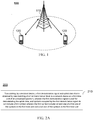
- the communication system 100 may include a network device 110.
- the network device 110 may be a device communicating with user equipment (UE) 120 (or referred to as a communication terminal or a terminal).
- UE user equipment
- the network device 110 may provide communication coverage to a specific geographic region, and may communicate with UE located within the coverage region.
- the network device 110 may be a base transceiver station (BTS) in a global system for mobile communications (GSM) or a code division multiple access (CDMA) system, or a nodeB (NB) in a wideband code division multiple access (WCDMA) system, or an evolutional node B (eNB or eNodeB) in a long term evolution (LTE) system, or a radio controller in a cloud radio access network (CRAN).
- BTS base transceiver station
- GSM global system for mobile communications
- CDMA code division multiple access
- NB wideband code division multiple access
- eNB or eNodeB evolutional node B
- LTE long term evolution
- CRAN cloud radio access network
- the network device may be a mobile switching center, a relay station, an access point, a vehicle device, a wearable device, a concentrator, a switchboard, a network bridge, a router, a network-side device in a 5th generation (5G) network, or a network device in a public land mobile network (PLMN) that will be evolved in the future, and the like.
- 5G 5th generation
- PLMN public land mobile network
- the communication system 100 further includes at least one UE 120 located within a coverage range of the network device 110.
- the "UE" used herein includes, but not limited to, connection via a wired line, such as connection via public switched telephone networks (PSTN), a digital subscriber line (DSL), a digital cable, and a direct cable; and/or another data connection/network; and/or via a wireless interface, for example, for a cellular network, a wireless local area network (WLAN), a digital television network such as a DVB-H network, a satellite network and an AM-FM broadcast transmitter; and/or an apparatus of another UE, which is configured to receive/transmit a communication signal; and/or an Internet of things (IoT) device.
- PSTN public switched telephone networks
- DSL digital subscriber line
- a digital cable and a direct cable
- a wireless interface for example, for a cellular network, a wireless local area network (WLAN), a digital television network such as a DVB-H network, a
- the UE configured to realize communication through a wireless interface may be referred to as a "wireless communication terminal", a “wireless terminal”, or a “mobile terminal”.
- the mobile terminal include, but not limited to, a satellite or cellular phone, and a personal communications system (PCS) terminal that may combine a cellular radiotelephone with data processing, facsimile, and data communication capabilities; a radiotelephone, a pager, an Internet/intranet access, a Web browser, a notepad, a calendar, and/or a personal digital assistant (PDA) of a global positioning system (GPS) receiver; and a conventional laptop and/or palmtop receiver or other electronic apparatuses including radiotelephone transceivers.
- PCS personal communications system
- the UE may refer to an access terminal, UE, a user unit, a user station, a mobile station, a mobile platform, a remote station, a remote terminal, a mobile device, a user terminal, a terminal, a wireless communication device, a user agent, or a user apparatus.
- the access terminal may be a cellular phone, a cordless telephone, a session initiation protocol (SIP) telephone, a wireless local loop (WLL) station, a PDA, a handheld device having a wireless communication function, a computation device or other processing devices connected to a radio modem, a vehicle device, a wearable device, UE in a 5G network, or UE in the PLMN that will be evolved in the future, and the like.
- SIP session initiation protocol
- WLL wireless local loop
- D2D device to device
- a 5G system or 5G network may also be referred to as a new radio (NR) system or NR network.
- NR new radio
- FIG. 1 exemplarily illustrates one network device and two UEs.
- the communication system 100 may include a plurality of network devices, and a coverage range of each network device may include other numbers of UEs, which is not limited by the embodiment of the present invention.
- the communication system 100 may also include other network entities such as a network controller and a mobile management entity, which is not limited by the embodiment of the present invention.
- a device having a communication function in a network/system in the embodiment of the present invention may be referred to as a communication device.
- the communication system 100 shown in FIG. 1 is taken as an example.
- the communication device may include a network device 110 and UE 120 which have communication functions.
- the network device 110 and the UE 120 may be the above-mentioned specific devices, and descriptions thereof are omitted here.
- the communication device may also include other devices in the communication system 100, such as other network entities including the network controller, the mobile management entity, and the like, which is not limited by the embodiment of the present invention.
- system and “network” herein may often be interchanged herein.
- the term “and/or” herein is only an association relationship that describes associated objects, and represents that there may be three relationships. For example, A and/or B may represent that: A exists alone, A and B exist simultaneously, and B exists alone.
- the character “/” herein generally indicates that front and back associated objects are in an "or” relationship.
- FIG. 2A is a schematic flowchart of an uplink signal transmission method 200 provided by an embodiment of the present application.
- a terminal device transmits a first demodulation signal and uplink data that is obtained by rate matching of a first transmission block to a network device on a first time unit of an unlicensed spectrum, and the first demodulation signal is used for demodulating the uplink data, and symbols occupied by the first demodulation signal do not include a first symbol.
- the first time unit may be a time slot, for example, the first time unit may include 14 symbols; or may also be a sub time slot (one sub time slot includes N symbols, where N is an integer greater than or equal to 2 and less than 14).
- the first time unit may include 7 symbols; or may be a set of multiple time slots, for example, the first time unit may include a set of 12 time slots; or may also be a set of multiple sub time slots, for example, the first time unit may include a set of 2 sub time slots, where one sub time slot includes 4 symbols, another sub time slot includes 7 symbols, and so on, which is not particularly limited in this embodiment.
- the first symbol may include but is not limited to at least one of a first one of the symbols in the first time unit and a last one of the symbols in the first time unit, which is not particularly limited in this embodiment.
- the first time unit being a time slot including 14 symbols is taken as an example.
- the symbols are numbered from 0, that is, one time slot includes symbol 0, symbol 1, ..., symbol 13, and the first symbol may include at least one of the symbol 0 and symbols 13.
- the terminal device may further send a second demodulation signal to the network device on the first time unit.
- the second demodulation signal is used for demodulating the uplink data, and the symbol occupied by the second demodulation signal does not include the first symbol.
- the first demodulation signal may include a demodulation reference signal (DMRS), and the second demodulation signal may include uplink control information (UCI), or the first demodulation signal may include UCI, and the second demodulation signal may include DMRS, which is not particularly limited in this embodiment.
- DMRS demodulation reference signal
- UCI uplink control information
- the symbol occupied by the second demodulation signal may further not include the symbol occupied by the first demodulation signal.
- the demodulation signal occupying a certain symbol may mean that the demodulation signal is transmitted by all or a portion of resources on the symbol, which is not particularly limited in this embodiment.
- the symbol occupied by the second demodulation signal may further include the symbol occupied by the first demodulation signal, that is, the first demodulation signal is transmitted by a portion of resources on the symbol, and the second demodulation signal is also transmitted by a portion of resources on the symbol.
- the symbol occupied by the second demodulation signal may be specifically determined according to the symbol occupied by the first demodulation signal.
- the symbol occupied by the second demodulation signal may include a first symbol after the symbol occupied by the first demodulation signal.
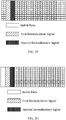
- the first time unit being a time slot including 14 symbols is taken as an example. The symbols are numbered from 0, that is, one time slot includes symbol 0, symbol 1, ..., symbol 13. If the first symbol is symbol 0, and the symbol occupied by the first demodulation signal is symbol 1, and the symbol occupied by the second demodulation signal may include symbol 2, as shown in FIG. 2B .
- the symbol occupied by the second demodulation signal may include a last symbol before the symbol occupied by the first demodulation signal.
- the first time unit being a time slot including 14 symbols is taken as an example. The symbols are numbered from 0, that is, one time slot includes symbol 0, symbol 1, ..., symbol 13. If the first symbol is symbol 0, and the symbol occupied by the first demodulation signal is symbol 3, and the symbol occupied by the second demodulation signal may include symbol 2, as shown in FIG. 2C .
- the second demodulation signal occupies multiple symbols, and a first symbol of the symbols occupied by the second demodulation signal is the first symbol after the symbol occupied by the first demodulation signal.
- the first time unit being a time slot including 14 symbols is taken as an example. The symbols are numbered from 0, that is, one time slot includes symbol 0, symbol 1, ..., symbol 13. If the first symbol is symbol 0, and the symbol occupied by the first demodulation signal is symbol 1, and the first symbol of the symbols occupied by the second demodulation signal may be symbol 2.
- the first demodulation signal occupies multiple symbols, and the symbols occupied by the second demodulation signal include a first symbol after the first symbol occupied by the first demodulation signal.
- the first time unit being a time slot including 14 symbols is taken as an example. The symbols are numbered from 0, that is, one time slot includes symbol 0, symbol 1, ..., symbol 13. If the first symbol is symbol 0, and the symbols occupied by the first demodulation signal are symbol 1 and symbol 8, and the symbols occupied by the second demodulation signal may include symbol 2.
- the terminal device cannot perform the transmission on a portion of the time-domain resources pre-configured by the network device, for example, symbols in special positions such as a first one of the symbols in one time slot (i.e., symbol 0) and a last one of the symbols in one time slot (i.e., symbol 13).
- the demodulation signal used for demodulating the uplink data occupies the portion of the pre-configured resources by the network device on which the terminal device cannot perform the transmission, thereby realizing correct transmission of the demodulation signal used for demodulating the uplink data on the unlicensed spectrum.
- the symbol occupied by DMRS is symbol 1 and the symbol occupied by UCI is symbol 2.
- the resources occupied by the uplink data include other resources in the time slot not occupied by DMRS and UCI.
- a mapping method in which transmission of physical uplink shared channel (PUSCH) of the configure grant uplink is performed in three consecutive time slots and a complete slot is transmitted during each slot can be shown in FIG. 2D .
- PUSCH physical uplink shared channel
- mapping method in which the transmission of PUSCH of the configure grant uplink is performed in three consecutive time slots and some symbols in the three consecutive time slots may not be transmitted can be shown in FIG. 2E , where X indicates no transmission.
- positions of DMRS and UCI are located on the symbols that cannot be discarded, thereby ensuring the correct transmission of the demodulation signal used for demodulating uplink data on the unlicensed spectrum.
- the symbol occupied by the first demodulation signal may be specified by a standard specification.
- the symbol occupied by the first demodulation signal may specifically include a second one of the symbols in the first time unit.
- the symbol occupied by the first demodulation signal may be transmitted by the network device to the terminal device through indication information.
- the indication information may be a physical layer signaling, or may also be a media access control (MAC) control element (CE) signaling, or may be a radio resource control (RRC) signaling, which is not particularly limited in this embodiment.
- MAC media access control
- CE control element
- RRC radio resource control
- the indication information may be indicated in an explicit manner or in as implicit manner.
- the network device indicates to the terminal device the symbol occupied by the first demodulation signal (or the first symbol occupied by the first demodulation signal, or the last symbol occupied by the first demodulation signal) by downlink control information (DCI).
- DCI downlink control information
- the DCI further includes information that the network device indicates that the terminal device can use or be prohibited the use of the first time unit.
- DCI format 1 corresponds to a symbol occupied by the first demodulation signal (for example, the first demodulation signal occupies symbol 3)
- DCI format 2 corresponds to another symbol occupied by the first demodulation signal (for example, the first demodulation signal occupies symbol 5).
- the terminal device receives the DCI format 1, it can determine that the symbols occupied by the first demodulation signal include symbol 3; when the terminal device receives the DCI format 2, it can determine that the symbols occupied by the first demodulation signal include symbol 5.
- the indication information may also be a combination of RRC signaling and physical layer signaling.
- the network device configures at least two configurations of symbols occupied by the first demodulation signal, and indicates to the terminal device which of the at least two configurations should be used in one uplink transmission through DCI.
- the UCI may include control information used for demodulating the uplink data. Therefore, the UCI may also be considered as a demodulation signal necessary for demodulating the uplink data.
- the UCI may include but not limited to at least one piece of the following information: a hybrid automatic repeat request (HARQ) identifier corresponding to the first transmission block, an identifier of the terminal device, a starting symbol of the first time unit, and an ending symbol of the first time unit and an indication of a code block group (CBG) included in the first transmission block.
- HARQ hybrid automatic repeat request
- CBG code block group
- a starting position of the uplink data mapped on the first time unit may include the first one of the symbols in the first time unit.
- the mapping of the uplink data starts from the first one of the symbols in the first time unit, and ends with the last one of the symbols in the first time unit.
- the first time unit being a time slot including 14 symbols is taken as an example.
- the symbols are numbered from 0, that is, one time slot includes symbol 0, symbol 1, ..., symbol 13. If the first symbol is symbol 0, and the symbol occupied by the first demodulation signal is symbol 1, the symbols occupied by the second demodulation signal may include symbol 2. Then, on the symbols 0, 3 to 13, the mapping of the uplink data starts from symbol 0, and ends with symbol 13, as shown in FIG. 2F .
- the mapping method is simple.
- the starting position of the uplink data mapped on the first time unit may include a symbol other than the first one of the symbols in the first time unit, and the uplink data is not mapped on the first one of the symbols in the first time unit.
- the mapping of the uplink data starts from the symbol other than the first one of the symbols in the first time unit, and ends with the last one of the symbols in the first time unit.
- the first time unit being a time slot including 14 symbols is taken as an example.
- the symbols are numbered from 0, that is, one time slot includes symbol 0, symbol 1, ..., symbol 13. If the first symbol is symbol 0, and the symbol occupied by the first demodulation signal is symbol 1, the symbols occupied by the second demodulation signal may include symbol 2.
- the mapping of the uplink data starts from symbol 3, and ends with symbol 13, and the uplink data is not mapped on symbol 0, as shown in FIG. 2G .
- the ending position of the uplink data mapped on the first time unit may include the first one of the symbols in the first time unit.
- the first time unit being a time slot including 14 symbols is taken as an example.
- the symbols are numbered from 0, that is, one time slot includes symbol 0, symbol 1, ..., symbol 13. If the first symbol is symbol 0, and the symbol occupied by the first demodulation signal is symbol 1, the symbols occupied by the second demodulation signal may include symbol 2. Then, on the symbols 0, 3 to 13, the mapping of the uplink data starts from symbol 3, and ends by returning to symbol 0 after reaching symbol 13, as shown in FIG. 2H .
- the mapping method is complex, but it can guarantee the transmission of the system information of the uplink data.
- the terminal device transmits the first demodulation signal and the uplink data that is obtained by rate matching of a first transmission block to the network device on the first time unit of the unlicensed spectrum, and the first demodulation signal is used for demodulating the uplink data, symbols occupied by the first demodulation signal do not include a first symbol; and the first symbol includes at least one of a first one of the symbols in the first time unit and a last one of the symbols in the first time unit.
- the technical solutions in the present application can avoid the demodulation signal used for demodulating the uplink data occupies the portion of the pre-configured resources by the network device on which the terminal device cannot perform the transmission, thereby realizing correct transmission of the demodulation signal used for demodulating the uplink data on the unlicensed spectrum.
- FIG. 3 is a schematic flowchart of another uplink signal transmission method 300 provided by an embodiment of the present application.
- a network device receives a first demodulation signal and uplink data that is obtained by rate matching of a first transmission block transmitted by a terminal device on a first time unit of an unlicensed spectrum, and the first demodulation signal is used for demodulating the uplink data, and symbols occupied by the first demodulation signal do not include a first symbol.
- the first time unit may be a time slot, for example, the first time unit may include 14 symbols; or may also be a sub time slot (one sub time slot includes N symbols, where N is an integer greater than or equal to 2 and less than 14).
- the first time unit may include 7 symbols; or may be a set of multiple time slots, for example, the first time unit may include a set of 12 time slots; or may also be a set of multiple sub time slots, for example, the first time unit may include a set of 2 sub time slots, where one sub time slot includes 4 symbols, another sub time slot includes 7 symbols, and so on, which is not particularly limited in this embodiment.
- the first symbol may include but is not limited to at least one of a first one of the symbols in the first time unit and a last one of the symbols in the first time unit, which is not particularly limited in this embodiment.
- the first time unit being a time slot including 14 symbols is taken as an example.
- the symbols are numbered from 0, that is, one time slot includes symbol 0, symbol 1, ..., symbol 13, and the first symbol may include at least one of the symbol 0 and symbols 13.
- the network device may further receive a second demodulation signal transmitted by the terminal device on the first time unit.
- the second demodulation signal is used for demodulating the uplink data, and the symbol occupied by the second demodulation signal does not include the first symbol.
- the first demodulation signal may include a demodulation reference signal (DMRS), and the second demodulation signal may include uplink control information (UCI), or the first demodulation signal may include UCI, and the second demodulation signal may include DMRS, which is not particularly limited in this embodiment.
- DMRS demodulation reference signal
- UCI uplink control information
- the symbol occupied by the second demodulation signal may further not include the symbol occupied by the first demodulation signal.
- the demodulation signal occupying a certain symbol may mean that the demodulation signal is transmitted by all or a portion of resources on the symbol, which is not particularly limited in this embodiment.
- the symbol occupied by the second demodulation signal may further include the symbol occupied by the first demodulation signal, that is, the first demodulation signal is transmitted by a portion of resources on the symbol, and the second demodulation signal is also transmitted by a portion of resources on the symbol.
- the symbol occupied by the second demodulation signal may be specifically determined according to the symbol occupied by the first demodulation signal.
- the symbol occupied by the second demodulation signal may include a first symbol after the symbol occupied by the first demodulation signal.
- the first time unit being a time slot including 14 symbols is taken as an example. The symbols are numbered from 0, that is, one time slot includes symbol 0, symbol 1, ..., symbol 13. If the first symbol is symbol 0, and the symbol occupied by the first demodulation signal is symbol 1, and the symbol occupied by the second demodulation signal may include symbol 2, as shown in FIG. 2B .
- the symbol occupied by the second demodulation signal may include a last symbol before the symbol occupied by the first demodulation signal.
- the first time unit being a time slot including 14 symbols is taken as an example. The symbols are numbered from 0, that is, one time slot includes symbol 0, symbol 1, ..., symbol 13. If the first symbol is symbol 0, and the symbol occupied by the first demodulation signal is symbol 3, and the symbol occupied by the second demodulation signal may include symbol 2, as shown in FIG. 2C .
- the second demodulation signal occupies multiple symbols, and a first symbol of the symbols occupied by the second demodulation signal is the first symbol after the symbol occupied by the first demodulation signal.
- the first time unit being a time slot including 14 symbols is taken as an example. The symbols are numbered from 0, that is, one time slot includes symbol 0, symbol 1, ..., symbol 13. If the first symbol is symbol 0, and the symbol occupied by the first demodulation signal is symbol 1, and the first symbol of the symbols occupied by the second demodulation signal may be symbol 2.
- the first demodulation signal occupies multiple symbols, and the symbols occupied by the second demodulation signal include a first symbol after the first symbol occupied by the first demodulation signal.
- the first time unit being a time slot including 14 symbols is taken as an example. The symbols are numbered from 0, that is, one time slot includes symbol 0, symbol 1, ..., symbol 13. If the first symbol is symbol 0, and the symbols occupied by the first demodulation signal are symbol 1 and symbol 8, and the symbols occupied by the second demodulation signal may include symbol 2.
- the terminal device cannot perform the transmission on a portion of the time-domain resources pre-configured by the network device, for example, symbols in special positions such as a first one of the symbols in one time slot (i.e., symbol 0) and a last one of the symbols in one time slot (i.e., symbol 13).
- the demodulation signal used for demodulating the uplink data occupies the portion of the pre-configured resources by the network device on which the terminal device cannot perform the transmission, thereby realizing correct transmission of the demodulation signal used for demodulating the uplink data on the unlicensed spectrum.
- the symbol occupied by DMRS is symbol 1 and the symbol occupied by UCI is symbol 2.
- the resources occupied by the uplink data include other resources in the time slot not occupied by DMRS and UCI.
- a mapping method in which transmission of physical uplink shared channel (PUSCH) of the configure grant uplink is performed in three consecutive time slots and a complete slot is transmitted during each slot can be shown in FIG. 2D .
- PUSCH physical uplink shared channel
- mapping method in which the transmission of PUSCH of the configure grant uplink is performed in three consecutive time slots and some symbols in the three consecutive time slots may not be transmitted can be shown in FIG. 2E , where X indicates no transmission.
- positions of DMRS and UCI are located on the symbols that cannot be discarded, thereby ensuring the correct transmission of the demodulation signal used for demodulating uplink data on the unlicensed spectrum.
- the symbol occupied by the first demodulation signal may be specified by a standard specification.
- the symbol occupied by the first demodulation signal may specifically include a second one of the symbols in the first time unit.
- the symbol occupied by the first demodulation signal may be transmitted by the network device to the terminal device through indication information.
- the indication information may be a physical layer signaling, or may also be a media access control (MAC) control element (CE) signaling, or may be a radio resource control (RRC) signaling, which is not particularly limited in this embodiment.
- MAC media access control
- CE control element
- RRC radio resource control
- the indication information may be indicated in an explicit manner or in as implicit manner.
- the network device indicates to the terminal device the symbol occupied by the first demodulation signal (or the first symbol occupied by the first demodulation signal, or the last symbol occupied by the first demodulation signal) by downlink control information (DCI).
- DCI downlink control information
- the DCI further includes information that the network device indicates that the terminal device can use or be prohibited the use of the first time unit.
- DCI format 1 corresponds to a symbol occupied by the first demodulation signal (for example, the first demodulation signal occupies symbol 3)
- DCI format 2 corresponds to another symbol occupied by the first demodulation signal (for example, the first demodulation signal occupies symbol 5).
- the terminal device receives the DCI format 1, it can determine that the symbols occupied by the first demodulation signal include symbol 3; when the terminal device receives the DCI format 2, it can determine that the symbols occupied by the first demodulation signal include symbol 5.
- the indication information may also be a combination of RRC signaling and physical layer signaling.
- the network device configures at least two configurations of symbols occupied by the first demodulation signal, and indicates to the terminal device which of the at least two configurations should be used in one uplink transmission through DCI.
- the UCI may include control information used for demodulating the uplink data. Therefore, the UCI may also be considered as a demodulation signal necessary for demodulating the uplink data.
- the UCI may include but not limited to at least one piece of the following information: a hybrid automatic repeat request (HARQ) identifier corresponding to the first transmission block, an identifier of the terminal device, a starting symbol of the first time unit, and an ending symbol of the first time unit and an indication of a code block group (CBG) included in the first transmission block.
- HARQ hybrid automatic repeat request
- CBG code block group
- a starting position of the uplink data mapped on the first time unit may include the first one of the symbols in the first time unit.
- the mapping of the uplink data starts from the first one of the symbols in the first time unit, and ends with the last one of the symbols in the first time unit.
- the first time unit being a time slot including 14 symbols is taken as an example.
- the symbols are numbered from 0, that is, one time slot includes symbol 0, symbol 1, ..., symbol 13. If the first symbol is symbol 0, and the symbol occupied by the first demodulation signal is symbol 1, the symbols occupied by the second demodulation signal may include symbol 2. Then, on the symbols 0, 3 to 13, the mapping of the uplink data starts from symbol 0, and ends with symbol 13, as shown in FIG. 2F .
- the mapping method is simple.
- the starting position of the uplink data mapped on the first time unit may include a symbol other than the first one of the symbols in the first time unit, and the uplink data is not mapped on the first one of the symbols in the first time unit.
- the mapping of the uplink data starts from the symbol other than the first one of the symbols in the first time unit, and ends with the last one of the symbols in the first time unit.
- the first time unit being a time slot including 14 symbols is taken as an example.
- the symbols are numbered from 0, that is, one time slot includes symbol 0, symbol 1, ..., symbol 13. If the first symbol is symbol 0, and the symbol occupied by the first demodulation signal is symbol 1, the symbols occupied by the second demodulation signal may include symbol 2.
- the mapping of the uplink data starts from symbol 3, and ends with symbol 13, and the uplink data is not mapped on symbol 0, as shown in FIG. 2G .
- the ending position of the uplink data mapped on the first time unit may include the first one of the symbols in the first time unit.
- the first time unit being a time slot including 14 symbols is taken as an example.
- the symbols are numbered from 0, that is, one time slot includes symbol 0, symbol 1, ..., symbol 13. If the first symbol is symbol 0, and the symbol occupied by the first demodulation signal is symbol 1, the symbols occupied by the second demodulation signal may include symbol 2. Then, on the symbols 0, 3 to 13, the mapping of the uplink data starts from symbol 3, and ends by returning to symbol 0 after reaching symbol 13, as shown in FIG. 2H .
- the mapping method is complex, but it can guarantee the transmission of the system information of the uplink data.
- the network device receives the first demodulation signal and the uplink data that is obtained by rate matching of a first transmission block transmitted by the terminal device on the first time unit of the unlicensed spectrum, and the first demodulation signal is used for demodulating the uplink data, symbols occupied by the first demodulation signal do not include a first symbol; and the first symbol includes at least one of a first one of the symbols in the first time unit and a last one of the symbols in the first time unit.
- the technical solutions in the present application can avoid the demodulation signal used for demodulating the uplink data occupies the portion of the pre-configured resources by the network device on which the terminal device cannot perform the transmission, thereby realizing correct transmission of the demodulation signal used for demodulating the uplink data on the unlicensed spectrum.
- FIG. 4 is a schematic block diagram of a terminal device 400 provided by an embodiment of the present application. As shown in FIG. 4 , this embodiment provides a terminal device 400 configured to the method in the embodiment corresponding to FIG. 2A .
- the terminal device 400 includes functional modules configured to the method in the embodiment corresponding to FIG. 2A .
- the terminal device 400 may include a transmitting unit 410, configured to transmit a first demodulation signal and uplink data that is obtained by rate matching of a first transmission block to a network device on a first time unit of an unlicensed spectrum, and the first demodulation signal is used for demodulating the uplink data, and symbols occupied by the first demodulation signal do not include a first symbol; the first symbol includes at least one of a first one of the symbols in the first time unit and a last one of the symbols in the first time unit, which is not particularly limited in this embodiment.
- the transmitting unit 410 may be further configured to transmit a second demodulation signal to the network device on the first time unit.
- the second demodulation signal is used for demodulating the uplink data, and the symbol occupied by the second demodulation signal does not include the first symbol.
- the symbol occupied by the second demodulation signal may further not include the symbol occupied by the first demodulation signal.
- the symbol occupied by the second demodulation signal may further include the symbol occupied by the first demodulation signal, that is, the first demodulation signal is transmitted by a portion of resources on the symbol, and the second demodulation signal is also transmitted by a portion of resources on the symbol.
- the symbol occupied by the second demodulation signal may be specifically determined according to the symbol occupied by the first demodulation signal.
- the symbol occupied by the first demodulation signal may be specified by a standard specification.
- the symbol occupied by the first demodulation signal may specifically include a second one of the symbols in the first time unit.
- the symbol occupied by the first demodulation signal may be transmitted by the network device to the terminal device through indication information.
- the indication information may be a physical layer signaling, or may also be a media access control (MAC) control element (CE) signaling, or may be a radio resource control (RRC) signaling, which is not particularly limited in this embodiment.
- MAC media access control
- CE control element
- RRC radio resource control
- the indication information may also be a combination of RRC signaling and physical layer signaling.
- the network device configures at least two configurations of symbols occupied by the first demodulation signal, and indicates to the terminal device which of the at least two configurations should be used in one uplink transmission through DCI.
- the first demodulation signal may include a demodulation reference signal (DMRS), and the second demodulation signal may include uplink control information (UCI), or the first demodulation signal may include UCI, and the second demodulation signal may include DMRS, which is not particularly limited in this embodiment.
- DMRS demodulation reference signal
- UCI uplink control information
- the UCI may include control information used for demodulating the uplink data. Therefore, the UCI may also be considered as a demodulation signal necessary for demodulating the uplink data.
- the UCI may include but not limited to at least one piece of the following information: a hybrid automatic repeat request (HARQ) identifier corresponding to the first transmission block, an identifier of the terminal device, a starting symbol of the first time unit, and an ending symbol of the first time unit and an indication of a code block group (CBG) included in the first transmission block.
- HARQ hybrid automatic repeat request
- CBG code block group
- a starting position of the uplink data mapped on the first time unit may include the first one of the symbols in the first time unit.
- the mapping of the uplink data starts from the first one of the symbols in the first time unit, and ends with the last one of the symbols in the first time unit.
- the first time unit being a time slot including 14 symbols is taken as an example.
- the symbols are numbered from 0, that is, one time slot includes symbol 0, symbol 1, ..., symbol 13. If the first symbol is symbol 0, and the symbol occupied by the first demodulation signal is symbol 1, the symbols occupied by the second demodulation signal may include symbol 2. Then, on the symbols 0, 3 to 13, the mapping of the uplink data starts from symbol 0, and ends with symbol 13, and the mapping method is simple.
- the starting position of the uplink data mapped on the first time unit may include a symbol other than the first one of the symbols in the first time unit, and the uplink data is not mapped on the first one of the symbols in the first time unit.
- the mapping of the uplink data starts from the symbol other than the first one of the symbols in the first time unit, and ends with the last one of the symbols in the first time unit.
- the first time unit being a time slot including 14 symbols is taken as an example.
- the symbols are numbered from 0, that is, one time slot includes symbol 0, symbol 1, ..., symbol 13. If the first symbol is symbol 0, and the symbol occupied by the first demodulation signal is symbol 1, the symbols occupied by the second demodulation signal may include symbol 2. Then, on the symbols 0, 3 to 13, the mapping of the uplink data starts from symbol 3, and ends with symbol 13, and the uplink data is not mapped on symbol 0.
- the ending position of the uplink data mapped on the first time unit may include the first one of the symbols in the first time unit.
- the first time unit being a time slot including 14 symbols is taken as an example.
- the symbols are numbered from 0, that is, one time slot includes symbol 0, symbol 1, ..., symbol 13. If the first symbol is symbol 0, and the symbol occupied by the first demodulation signal is symbol 1, the symbols occupied by the second demodulation signal may include symbol 2. Then, on the symbols 0, 3 to 13, the mapping of the uplink data starts from symbol 3, and ends by returning to symbol 0 after reaching symbol 13.
- the mapping method is complex, but it can guarantee the transmission of the system information of the uplink data.
- FIG. 5 is a schematic block diagram of a network device 500 provided by an embodiment of the present application. As shown in FIG. 5 , this embodiment provides a network device configured to the method in the embodiment corresponding to FIG. 3 .
- the network device 500 includes functional modules configured to the method in the embodiment corresponding to FIG. 3 .
- the network device 500 may include a receiving unit 510, configured to receive a first demodulation signal and uplink data that is obtained by rate matching of a first transmission block transmitted by a terminal device on a first time unit of an unlicensed spectrum, and the first demodulation signal is used for demodulating the uplink data, and symbols occupied by the first demodulation signal do not include a first symbol;
- the first symbol includes at least one of a first one of the symbols in the first time unit and a last one of the symbols in the first time unit, which is not particularly limited in this embodiment.
- the receiving unit 510 may be further configured to receive a second demodulation signal transmitted by the terminal device on the first time unit.
- the second demodulation signal is used for demodulating the uplink data, and the symbol occupied by the second demodulation signal does not include the first symbol.
- the symbol occupied by the second demodulation signal may further not include the symbol occupied by the first demodulation signal.
- the symbol occupied by the second demodulation signal may further include the symbol occupied by the first demodulation signal, that is, the first demodulation signal is transmitted by a portion of resources on the symbol, and the second demodulation signal is also transmitted by a portion of resources on the symbol.
- the symbol occupied by the second demodulation signal may be specifically determined according to the symbol occupied by the first demodulation signal.
- the symbol occupied by the first demodulation signal may be specified by a standard specification.
- the symbol occupied by the first demodulation signal may specifically include a second one of the symbols in the first time unit.
- the symbol occupied by the first demodulation signal may be transmitted by the network device to the terminal device through indication information.
- the indication information may be a physical layer signaling, or may also be a media access control (MAC) control element (CE) signaling, or may be a radio resource control (RRC) signaling, which is not particularly limited in this embodiment.
- MAC media access control
- CE control element
- RRC radio resource control
- the indication information may also be a combination of RRC signaling and physical layer signaling.
- the network device configures at least two configurations of symbols occupied by the first demodulation signal, and indicates to the terminal device which of the at least two configurations should be used in one uplink transmission through DCI.
- the first demodulation signal may include a demodulation reference signal (DMRS), and the second demodulation signal may include uplink control information (UCI), or the first demodulation signal may include UCI, and the second demodulation signal may include DMRS, which is not particularly limited in this embodiment.
- DMRS demodulation reference signal
- UCI uplink control information
- the UCI may include control information used for demodulating the uplink data. Therefore, the UCI may also be considered as a demodulation signal necessary for demodulating the uplink data.
- the UCI may include but not limited to at least one piece of the following information: a hybrid automatic repeat request (HARQ) identifier corresponding to the first transmission block, an identifier of the terminal device, a starting symbol of the first time unit, and an ending symbol of the first time unit and an indication of a code block group (CBG) included in the first transmission block.
- HARQ hybrid automatic repeat request
- CBG code block group
- a starting position of the uplink data mapped on the first time unit may include the first one of the symbols in the first time unit.
- the mapping of the uplink data starts from the first one of the symbols in the first time unit, and ends with the last one of the symbols in the first time unit.
- the first time unit being a time slot including 14 symbols is taken as an example.
- the symbols are numbered from 0, that is, one time slot includes symbol 0, symbol 1, ..., symbol 13. If the first symbol is symbol 0, and the symbol occupied by the first demodulation signal is symbol 1, the symbols occupied by the second demodulation signal may include symbol 2. Then, on the symbols 0, 3 to 13, the mapping of the uplink data starts from symbol 0, and ends with symbol 13, and the mapping method is simple.
- the starting position of the uplink data mapped on the first time unit may include a symbol other than the first one of the symbols in the first time unit, and the uplink data is not mapped on the first one of the symbols in the first time unit.
- the mapping of the uplink data starts from the symbol other than the first one of the symbols in the first time unit, and ends with the last one of the symbols in the first time unit.
- the first time unit being a time slot including 14 symbols is taken as an example.
- the symbols are numbered from 0, that is, one time slot includes symbol 0, symbol 1, ..., symbol 13. If the first symbol is symbol 0, and the symbol occupied by the first demodulation signal is symbol 1, the symbols occupied by the second demodulation signal may include symbol 2. Then, on the symbols 0, 3 to 13, the mapping of the uplink data starts from symbol 3, and ends with symbol 13, and the uplink data is not mapped on symbol 0.
- the ending position of the uplink data mapped on the first time unit may include the first one of the symbols in the first time unit.
- the first time unit being a time slot including 14 symbols is taken as an example.
- the symbols are numbered from 0, that is, one time slot includes symbol 0, symbol 1, ..., symbol 13. If the first symbol is symbol 0, and the symbol occupied by the first demodulation signal is symbol 1, the symbols occupied by the second demodulation signal may include symbol 2. Then, on the symbols 0, 3 to 13, the mapping of the uplink data starts from symbol 3, and ends by returning to symbol 0 after reaching symbol 13.
- the mapping method is complex, but it can guarantee the transmission of the system information of the uplink data.
- FIG. 6 is a schematic structural diagram of a communications device 600 according to an embodiment of the present application.
- the communications device 600 shown in FIG. 6 includes a processor 610.
- the processor 610 may invoke a computer program from a memory and run the computer program, to implement the method in the embodiments of the present application.
- the communications device 600 may further include a memory 620.
- the processor 610 may invoke the computer program from the memory 620 and run the computer program, to implement the method in the embodiments of the present application.
- the memory 620 may be a component independent of the processor 610, or may be integrated into the processor 610.
- the communications device 600 may further include a transceiver 630.
- the processor 610 may control the transceiver 630 to communicate with another device, and specifically, the transceiver 630 may send information or data to another device, or receive information or data sent by another device.
- the transceiver 630 may include a transmitter and a receiver.
- the transceiver 630 may further include an antenna. There may be one or more antennas.
- the communications device 600 may be the network device in the embodiments of the present application, and the communications device 600 can implement corresponding procedures implemented by the network device in various methods in the embodiments of the present application. For brevity, details are not described herein again.
- the communications device 600 may be the terminal device in the embodiments of the present application, and the communications device 600 can implement corresponding procedures implemented by the terminal device in various methods in the embodiments of the present application. For brevity, details are not described herein again.
- FIG. 7 is a schematic structural diagram of a chip 700 according to an embodiment of the present application.
- the chip 700 shown in FIG. 7 includes a processor 710.
- the processor 710 may invoke a computer program from a memory and run the computer program, to implement the method in the embodiments of the present application.
- the chip 700 may further include a memory 720.
- the processor 710 may invoke the computer program from the memory 720 and run the computer program, to implement the method in the embodiments of the present application.
- the memory 720 may be a component independent of the processor 710, or may be integrated into the processor 710.
- the chip 700 may further include an input interface 730.
- the processor 710 may control the input interface 730 to communicate with another device or chip, and specifically, the input interface 730 may obtain information or data sent by another device or chip.
- the chip 700 may further include an output interface 740.
- the processor 710 may control the output interface 740 to communicate with another device or chip, and specifically, the output interface 740 may output information or data to another device or chip
- the chip may be applied to the network device in the embodiments of the present application, and the chip can implement corresponding procedures implemented by the network device in various methods in the embodiments of the present application.
- the chip may be applied to the network device in the embodiments of the present application, and the chip can implement corresponding procedures implemented by the network device in various methods in the embodiments of the present application.
- details are not described herein again.
- the chip may be applied to the mobile terminal/terminal device in the embodiments of the present application, and the chip can implement corresponding procedures implemented by the mobile terminal/terminal device in various methods in the embodiments of the present application.
- the chip may be applied to the mobile terminal/terminal device in the embodiments of the present application, and the chip can implement corresponding procedures implemented by the mobile terminal/terminal device in various methods in the embodiments of the present application.
- details are not described herein again.
- the chip mentioned in the embodiments of the present application may also be referred to as a system-level chip, a system chip, a chip system, a system on chip, or the like.
- FIG. 8 is a schematic structural diagram of a communication system 800 according to an embodiment of the present application.
- the communication system 800 shown in FIG. 8 includes a terminal device 810 and a network device 820.
- the terminal device 810 can implement corresponding functions implemented by the terminal device in the foregoing method and the network device 820 can implement corresponding functions implemented by the network device in the foregoing method. For brevity, details are not described herein again.
- the processor of the embodiments of the present application may be an integrated circuit chip, has a signal processing capability, the steps of the foregoing method embodiment may be implemented by using a hardware integrated logic circuit in the processor and/or implemented by using an instruction in a software form.
- the foregoing processor may be a general purpose processor, a digital signal processor (DSP), a field programmable gate array (FPGA), an application specific integrated circuit (ASIC) or another programmable logic device, a transistor logic device, or a discrete hardware component.
- DSP digital signal processor
- FPGA field programmable gate array
- ASIC application specific integrated circuit
- the foregoing general purpose processor may be a microprocessor, or may be any conventional processor, or the like.
- Steps of the methods disclosed with reference to the embodiments of the present invention may be directly executed and completed by means of a hardware decoding processor, or may be executed and completed by using a combination of hardware and software modules in the decoding processor.
- the software module may be located in a mature storage medium in the field, such as a random access memory, a flash memory, a read-only memory, a programmable read-only memory, an electrically-erasable programmable memory, or a register.
- the storage medium is located in the memory, and the processor reads information in the memory and completes the steps in the foregoing method embodiments in combination with hardware of the processor.
- the memory in the embodiments of the present application may be a volatile memory or a non-volatile memory, or may include both a volatile memory and a non-volatile memory.
- the non-volatile memory may be a read-only memory (ROM), a programmable ROM (PROM), an erasable PROM (EPROM), an electrically EPROM (EEPROM), or a flash memory.
- the volatile memory may be a random access memory (RAM), and is used as an external cache.
- RAM random access memory
- DRAM dynamic random access memory
- SDRAM synchronous dynamic random access memory
- DDRSDRAM double data rate synchronous dynamic random access memory
- ESDRAM enhanced synchronous dynamic random access memory
- SLDRAM synclink dynamic random access memory
- DRRAM direct rambus random access memory
- the memory is an example but is not intended for limitation.
- the memory in the embodiments of the present application may alternatively be a static RAM (SRAM), a dynamic RAM (DRAM), a synchronous DRAM (SDRAM), a double data rate SDRAM (DDR SDRAM), an enhanced SDRAM (ESDRAM), a synch link DRAM (SLDRAM), a direct rambus RAM (DR RAM), and the like. That is, the memory described in this embodiment of the present application is intended to include but is not limited to these memories and any other suitable type of memory.
- An embodiment of the present application further provides a computer readable storage medium.
- the computer readable storage medium is configured to store a computer program.
- the computer readable storage medium may be applied to the network device in the embodiments of the present application, and the computer program enables a computer to execute a corresponding procedure implemented by the network device in the methods of the embodiments of the present application.
- the computer program enables a computer to execute a corresponding procedure implemented by the network device in the methods of the embodiments of the present application.
- the computer readable storage medium may be applied to the terminal device in the embodiments of the present application, and the computer program enables the computer to execute a corresponding procedure implemented by the terminal device in the methods of the embodiments of the present application.
- the computer program enables the computer to execute a corresponding procedure implemented by the terminal device in the methods of the embodiments of the present application.
- the present application further provides a computer program product.
- the computer program product includes a computer program instruction.
- the computer program product may be applied to the network device in the embodiments of the present application, and the computer program instruction enables the computer to execute a corresponding procedure implemented by the network device in the methods of the embodiments of the present application.
- the computer program instruction enables the computer to execute a corresponding procedure implemented by the network device in the methods of the embodiments of the present application.
- the computer program product may be applied to the terminal device in the embodiments of the present application, and the computer program instruction enables the computer to execute a corresponding procedure implemented by the terminal device in the methods of the embodiments of the present application.
- the computer program instruction enables the computer to execute a corresponding procedure implemented by the terminal device in the methods of the embodiments of the present application.
- the present application further provides a computer program.
- the computer program may be applied to the network device in the embodiments of the present application, and when run on a computer, the computer program instruction enables the computer to execute a corresponding procedure implemented by the network device in the methods of the embodiments of the present application.
- the computer program instruction enables the computer to execute a corresponding procedure implemented by the network device in the methods of the embodiments of the present application.
- the computer program may be applied to the terminal device in the embodiments of the present application, and when run on a computer, the computer program instruction enables the computer to execute a corresponding procedure implemented by the terminal device in the methods of the embodiments of the present application.
- the computer program instruction enables the computer to execute a corresponding procedure implemented by the terminal device in the methods of the embodiments of the present application.
- the disclosed system, apparatus, and method may be implemented in other manners.
- the apparatus embodiments described above are merely examples.
- the unit division is merely logical function division, and there may be other division manners in actual implementation.
- a plurality of units or components may be combined or integrated into another system, or some features may be ignored or not performed.
- the displayed or discussed mutual couplings or direct couplings or communication connections may be implemented by using some interfaces.
- the indirect couplings or communication connections between the apparatuses or units may be implemented in electrical, mechanical, or other forms.
- the units described as separate parts may or may not be physically separate, and the parts displayed as units may or may not be physical units, may be located in one position, or may be distributed on multiple network units. Some of or all of the units may be selected according to actual needs to achieve the objectives of the solutions of the embodiments.
- the functions When the functions are implemented in the form of a software functional unit and sold or used as an independent product, the functions may be stored in a computer-readable storage medium.
- the software product is stored in a storage medium, and includes several instructions for instructing a computer device (which may be a personal computer, a server, or a network device) to perform all or some of the steps of the methods described in the embodiments of the present application.
- the foregoing storage medium includes: any medium that can store program code, such as a USB flash drive, a removable hard disk, a read-only memory (ROM), a random access memory (RAM), a magnetic disk, or an optical disc.
Landscapes
- Engineering & Computer Science (AREA)
- Signal Processing (AREA)
- Computer Networks & Wireless Communication (AREA)
- Quality & Reliability (AREA)
- Mobile Radio Communication Systems (AREA)
Applications Claiming Priority (2)
| Application Number | Priority Date | Filing Date | Title |
|---|---|---|---|
| CN201810671335 | 2018-06-26 | ||
| PCT/CN2019/086827 WO2020001183A1 (fr) | 2018-06-26 | 2019-05-14 | Procédé de transmission de signal de liaison montante, dispositif terminal et dispositif de réseau |
Publications (3)
| Publication Number | Publication Date |
|---|---|
| EP3817482A1 true EP3817482A1 (fr) | 2021-05-05 |
| EP3817482A4 EP3817482A4 (fr) | 2021-08-04 |
| EP3817482B1 EP3817482B1 (fr) | 2024-01-24 |
Family
ID=68985499
Family Applications (1)
| Application Number | Title | Priority Date | Filing Date |
|---|---|---|---|
| EP19827473.0A Active EP3817482B1 (fr) | 2018-06-26 | 2019-05-14 | Procédé de transmission de signal de liaison montante, dispositif terminal et dispositif de réseau |
Country Status (7)
| Country | Link |
|---|---|
| US (1) | US11510067B2 (fr) |
| EP (1) | EP3817482B1 (fr) |
| JP (1) | JP2021529456A (fr) |
| KR (1) | KR20210022672A (fr) |
| CN (1) | CN112335309A (fr) |
| AU (1) | AU2019296665A1 (fr) |
| WO (1) | WO2020001183A1 (fr) |
Families Citing this family (3)
| Publication number | Priority date | Publication date | Assignee | Title |
|---|---|---|---|---|
| KR20210022672A (ko) | 2018-06-26 | 2021-03-03 | 광동 오포 모바일 텔레커뮤니케이션즈 코포레이션 리미티드 | 상향 신호의 전송 방법, 단말기 디바이스 및 네트워크 디바이스 |
| EP3840463A4 (fr) * | 2018-08-17 | 2021-12-29 | Guangdong Oppo Mobile Telecommunications Corp., Ltd. | Procédé de communication sans fil, et dispositif de communication sans fil |
| CN115515251A (zh) * | 2021-06-23 | 2022-12-23 | 中兴通讯股份有限公司 | 网络接入方法、设备和存储介质 |
Family Cites Families (12)
| Publication number | Priority date | Publication date | Assignee | Title |
|---|---|---|---|---|
| US20140286255A1 (en) * | 2013-03-25 | 2014-09-25 | Samsung Electronics Co., Ltd. | Uplink demodulation reference signals in advanced wireless communication systems |
| RU2653495C1 (ru) * | 2014-09-25 | 2018-05-10 | Телефонактиеболагет Лм Эрикссон (Пабл) | Способ и устройство для улучшенного опорного сигнала восходящей линии связи в системах listen-before-talk |
| WO2016122122A1 (fr) * | 2015-01-29 | 2016-08-04 | Samsung Electronics Co., Ltd. | Procédé et appareil de transmission d'informations de commande de liaison montante |
| CN106304100A (zh) * | 2015-06-28 | 2017-01-04 | 上海无线通信研究中心 | 一种共存于未授权频带的多通信系统分时传输方法 |
| CN106452704B (zh) * | 2015-08-13 | 2020-10-16 | 中国移动通信集团公司 | 一种发现参考信号的发送方法、基站及终端 |
| PL3400745T3 (pl) * | 2016-01-06 | 2025-02-10 | Apple Inc. | Metoda i urządzenie dostępu do kanału laa lte uplink do transmisji i odbierania pasma użytkownika i danych pasma sterowania |
| CN106211337B (zh) * | 2016-06-21 | 2019-03-29 | 浙江大学 | 免授权频段基于有效帧号的资源定位方法 |
| CN108023671B (zh) * | 2016-11-04 | 2022-03-29 | 中兴通讯股份有限公司 | 一种数据传输方法、基站、用户设备及系统 |
| US11412534B2 (en) * | 2016-11-04 | 2022-08-09 | Qualcomm Incorporated | System and method for mapping uplink control information |
| US10492184B2 (en) * | 2016-12-09 | 2019-11-26 | Samsung Electronics Co., Ltd. | Multiplexing control information in a physical uplink data channel |
| US10880058B2 (en) * | 2017-04-25 | 2020-12-29 | Qualcomm Incorporated | Transmitting uplink control information (UCI) |
| KR20210022672A (ko) | 2018-06-26 | 2021-03-03 | 광동 오포 모바일 텔레커뮤니케이션즈 코포레이션 리미티드 | 상향 신호의 전송 방법, 단말기 디바이스 및 네트워크 디바이스 |
-
2019
- 2019-05-14 KR KR1020217001566A patent/KR20210022672A/ko not_active Withdrawn
- 2019-05-14 EP EP19827473.0A patent/EP3817482B1/fr active Active
- 2019-05-14 CN CN201980040597.3A patent/CN112335309A/zh active Pending
- 2019-05-14 JP JP2020571457A patent/JP2021529456A/ja active Pending
- 2019-05-14 WO PCT/CN2019/086827 patent/WO2020001183A1/fr not_active Ceased
- 2019-05-14 AU AU2019296665A patent/AU2019296665A1/en not_active Abandoned
-
2020
- 2020-12-21 US US17/129,639 patent/US11510067B2/en active Active
Also Published As
| Publication number | Publication date |
|---|---|
| US20210112421A1 (en) | 2021-04-15 |
| US11510067B2 (en) | 2022-11-22 |
| EP3817482B1 (fr) | 2024-01-24 |
| CN112335309A (zh) | 2021-02-05 |
| WO2020001183A1 (fr) | 2020-01-02 |
| JP2021529456A (ja) | 2021-10-28 |
| KR20210022672A (ko) | 2021-03-03 |
| EP3817482A4 (fr) | 2021-08-04 |
| AU2019296665A1 (en) | 2021-02-04 |
Similar Documents
| Publication | Publication Date | Title |
|---|---|---|
| JP7465289B2 (ja) | 制御情報の伝送方法、端末装置及びネットワーク装置 | |
| US12003450B2 (en) | Signal transmission method and device and terminal | |
| WO2020051774A1 (fr) | Procédé de communication, dispositif terminal et dispositif de réseau | |
| WO2019242452A1 (fr) | Procédé et appareil d'accès à un canal de transmission de canal physique d'accès aléatoire et programme | |
| WO2020198983A1 (fr) | Procédé et appareil de communication sans fil pour spectre de fréquence sans licence et dispositif de communication | |
| TW202008838A (zh) | 一種隨機存取方法、終端設備及存儲媒介 | |
| CN114501651B (zh) | 确定时隙格式的方法及装置 | |
| TW202025838A (zh) | 通訊方法、終端設備和網路設備 | |
| WO2020220358A1 (fr) | Procédé et appareil de réglage de puissance pour spectre sans licence | |
| WO2020062068A1 (fr) | Procédé de communication sans fil, dispositif de terminal et dispositif de réseau | |
| US11510067B2 (en) | Uplink signal transmission method, terminal device, and network device | |
| WO2020061776A1 (fr) | Procédé de multiplexage de ressources de rétroaction, équipement terminal et dispositif réseau | |
| CN112929975B (zh) | 一种资源确定及配置方法、装置、终端、网络设备 | |
| US20210127426A1 (en) | Method for indicating channel access type, terminal device and network device | |
| WO2020087540A1 (fr) | Procédé de transmission d'informations de commande, dispositifs et support de stockage | |
| US11956666B2 (en) | HARQ process determination method, network device and terminal | |
| WO2020020335A1 (fr) | Procédé et appareil d'accès aléatoire | |
| WO2020199171A1 (fr) | Procédé et appareil de détermination de paramètre de transmission et équipement utilisateur | |
| CN114339664B (zh) | 一种链路传输方法、终端设备及存储介质 |
Legal Events
| Date | Code | Title | Description |
|---|---|---|---|
| STAA | Information on the status of an ep patent application or granted ep patent |
Free format text: STATUS: THE INTERNATIONAL PUBLICATION HAS BEEN MADE |
|
| PUAI | Public reference made under article 153(3) epc to a published international application that has entered the european phase |
Free format text: ORIGINAL CODE: 0009012 |
|
| STAA | Information on the status of an ep patent application or granted ep patent |
Free format text: STATUS: REQUEST FOR EXAMINATION WAS MADE |
|
| 17P | Request for examination filed |
Effective date: 20210113 |
|
| AK | Designated contracting states |
Kind code of ref document: A1 Designated state(s): AL AT BE BG CH CY CZ DE DK EE ES FI FR GB GR HR HU IE IS IT LI LT LU LV MC MK MT NL NO PL PT RO RS SE SI SK SM TR |
|
| REG | Reference to a national code |
Ref country code: DE Free format text: PREVIOUS MAIN CLASS: H04W0072040000 Ref country code: DE Ref legal event code: R079 Ref document number: 602019045724 Country of ref document: DE Free format text: PREVIOUS MAIN CLASS: H04W0072040000 Ipc: H04L0005000000 |
|
| A4 | Supplementary search report drawn up and despatched |
Effective date: 20210701 |
|
| RIC1 | Information provided on ipc code assigned before grant |
Ipc: H04L 5/00 20060101AFI20210625BHEP Ipc: H04W 72/04 20090101ALI20210625BHEP Ipc: H04L 1/00 20060101ALI20210625BHEP Ipc: H04W 16/14 20090101ALI20210625BHEP |
|
| DAV | Request for validation of the european patent (deleted) | ||
| DAX | Request for extension of the european patent (deleted) | ||
| GRAP | Despatch of communication of intention to grant a patent |
Free format text: ORIGINAL CODE: EPIDOSNIGR1 |
|
| STAA | Information on the status of an ep patent application or granted ep patent |
Free format text: STATUS: GRANT OF PATENT IS INTENDED |
|
| INTG | Intention to grant announced |
Effective date: 20230912 |
|
| GRAS | Grant fee paid |
Free format text: ORIGINAL CODE: EPIDOSNIGR3 |
|
| GRAA | (expected) grant |
Free format text: ORIGINAL CODE: 0009210 |
|
| STAA | Information on the status of an ep patent application or granted ep patent |
Free format text: STATUS: THE PATENT HAS BEEN GRANTED |
|
| AK | Designated contracting states |
Kind code of ref document: B1 Designated state(s): AL AT BE BG CH CY CZ DE DK EE ES FI FR GB GR HR HU IE IS IT LI LT LU LV MC MK MT NL NO PL PT RO RS SE SI SK SM TR |
|
| REG | Reference to a national code |
Ref country code: GB Ref legal event code: FG4D |
|
| REG | Reference to a national code |
Ref country code: CH Ref legal event code: EP |
|
| REG | Reference to a national code |
Ref country code: IE Ref legal event code: FG4D |
|
| REG | Reference to a national code |
Ref country code: DE Ref legal event code: R096 Ref document number: 602019045724 Country of ref document: DE |
|
| REG | Reference to a national code |
Ref country code: LT Ref legal event code: MG9D |
|
| REG | Reference to a national code |
Ref country code: NL Ref legal event code: MP Effective date: 20240124 |
|
| P01 | Opt-out of the competence of the unified patent court (upc) registered |
Effective date: 20240521 |
|
| PG25 | Lapsed in a contracting state [announced via postgrant information from national office to epo] |
Ref country code: NL Free format text: LAPSE BECAUSE OF FAILURE TO SUBMIT A TRANSLATION OF THE DESCRIPTION OR TO PAY THE FEE WITHIN THE PRESCRIBED TIME-LIMIT Effective date: 20240124 |
|
| PG25 | Lapsed in a contracting state [announced via postgrant information from national office to epo] |
Ref country code: NL Free format text: LAPSE BECAUSE OF FAILURE TO SUBMIT A TRANSLATION OF THE DESCRIPTION OR TO PAY THE FEE WITHIN THE PRESCRIBED TIME-LIMIT Effective date: 20240124 |
|
| PG25 | Lapsed in a contracting state [announced via postgrant information from national office to epo] |
Ref country code: IS Free format text: LAPSE BECAUSE OF FAILURE TO SUBMIT A TRANSLATION OF THE DESCRIPTION OR TO PAY THE FEE WITHIN THE PRESCRIBED TIME-LIMIT Effective date: 20240524 |
|
| PG25 | Lapsed in a contracting state [announced via postgrant information from national office to epo] |
Ref country code: LT Free format text: LAPSE BECAUSE OF FAILURE TO SUBMIT A TRANSLATION OF THE DESCRIPTION OR TO PAY THE FEE WITHIN THE PRESCRIBED TIME-LIMIT Effective date: 20240124 |
|
| PG25 | Lapsed in a contracting state [announced via postgrant information from national office to epo] |
Ref country code: GR Free format text: LAPSE BECAUSE OF FAILURE TO SUBMIT A TRANSLATION OF THE DESCRIPTION OR TO PAY THE FEE WITHIN THE PRESCRIBED TIME-LIMIT Effective date: 20240425 |
|
| REG | Reference to a national code |
Ref country code: AT Ref legal event code: MK05 Ref document number: 1653013 Country of ref document: AT Kind code of ref document: T Effective date: 20240124 |
|
| PG25 | Lapsed in a contracting state [announced via postgrant information from national office to epo] |
Ref country code: HR Free format text: LAPSE BECAUSE OF FAILURE TO SUBMIT A TRANSLATION OF THE DESCRIPTION OR TO PAY THE FEE WITHIN THE PRESCRIBED TIME-LIMIT Effective date: 20240124 Ref country code: RS Free format text: LAPSE BECAUSE OF FAILURE TO SUBMIT A TRANSLATION OF THE DESCRIPTION OR TO PAY THE FEE WITHIN THE PRESCRIBED TIME-LIMIT Effective date: 20240424 |
|
| PG25 | Lapsed in a contracting state [announced via postgrant information from national office to epo] |
Ref country code: ES Free format text: LAPSE BECAUSE OF FAILURE TO SUBMIT A TRANSLATION OF THE DESCRIPTION OR TO PAY THE FEE WITHIN THE PRESCRIBED TIME-LIMIT Effective date: 20240124 |
|
| PG25 | Lapsed in a contracting state [announced via postgrant information from national office to epo] |
Ref country code: AT Free format text: LAPSE BECAUSE OF FAILURE TO SUBMIT A TRANSLATION OF THE DESCRIPTION OR TO PAY THE FEE WITHIN THE PRESCRIBED TIME-LIMIT Effective date: 20240124 |
|
| PG25 | Lapsed in a contracting state [announced via postgrant information from national office to epo] |
Ref country code: RS Free format text: LAPSE BECAUSE OF FAILURE TO SUBMIT A TRANSLATION OF THE DESCRIPTION OR TO PAY THE FEE WITHIN THE PRESCRIBED TIME-LIMIT Effective date: 20240424 Ref country code: NO Free format text: LAPSE BECAUSE OF FAILURE TO SUBMIT A TRANSLATION OF THE DESCRIPTION OR TO PAY THE FEE WITHIN THE PRESCRIBED TIME-LIMIT Effective date: 20240424 Ref country code: LT Free format text: LAPSE BECAUSE OF FAILURE TO SUBMIT A TRANSLATION OF THE DESCRIPTION OR TO PAY THE FEE WITHIN THE PRESCRIBED TIME-LIMIT Effective date: 20240124 Ref country code: IS Free format text: LAPSE BECAUSE OF FAILURE TO SUBMIT A TRANSLATION OF THE DESCRIPTION OR TO PAY THE FEE WITHIN THE PRESCRIBED TIME-LIMIT Effective date: 20240524 Ref country code: HR Free format text: LAPSE BECAUSE OF FAILURE TO SUBMIT A TRANSLATION OF THE DESCRIPTION OR TO PAY THE FEE WITHIN THE PRESCRIBED TIME-LIMIT Effective date: 20240124 Ref country code: GR Free format text: LAPSE BECAUSE OF FAILURE TO SUBMIT A TRANSLATION OF THE DESCRIPTION OR TO PAY THE FEE WITHIN THE PRESCRIBED TIME-LIMIT Effective date: 20240425 Ref country code: FI Free format text: LAPSE BECAUSE OF FAILURE TO SUBMIT A TRANSLATION OF THE DESCRIPTION OR TO PAY THE FEE WITHIN THE PRESCRIBED TIME-LIMIT Effective date: 20240124 Ref country code: ES Free format text: LAPSE BECAUSE OF FAILURE TO SUBMIT A TRANSLATION OF THE DESCRIPTION OR TO PAY THE FEE WITHIN THE PRESCRIBED TIME-LIMIT Effective date: 20240124 Ref country code: BG Free format text: LAPSE BECAUSE OF FAILURE TO SUBMIT A TRANSLATION OF THE DESCRIPTION OR TO PAY THE FEE WITHIN THE PRESCRIBED TIME-LIMIT Effective date: 20240124 Ref country code: AT Free format text: LAPSE BECAUSE OF FAILURE TO SUBMIT A TRANSLATION OF THE DESCRIPTION OR TO PAY THE FEE WITHIN THE PRESCRIBED TIME-LIMIT Effective date: 20240124 |
|
| PG25 | Lapsed in a contracting state [announced via postgrant information from national office to epo] |
Ref country code: PT Free format text: LAPSE BECAUSE OF FAILURE TO SUBMIT A TRANSLATION OF THE DESCRIPTION OR TO PAY THE FEE WITHIN THE PRESCRIBED TIME-LIMIT Effective date: 20240524 Ref country code: PL Free format text: LAPSE BECAUSE OF FAILURE TO SUBMIT A TRANSLATION OF THE DESCRIPTION OR TO PAY THE FEE WITHIN THE PRESCRIBED TIME-LIMIT Effective date: 20240124 |
|
| PG25 | Lapsed in a contracting state [announced via postgrant information from national office to epo] |
Ref country code: SE Free format text: LAPSE BECAUSE OF FAILURE TO SUBMIT A TRANSLATION OF THE DESCRIPTION OR TO PAY THE FEE WITHIN THE PRESCRIBED TIME-LIMIT Effective date: 20240124 Ref country code: PT Free format text: LAPSE BECAUSE OF FAILURE TO SUBMIT A TRANSLATION OF THE DESCRIPTION OR TO PAY THE FEE WITHIN THE PRESCRIBED TIME-LIMIT Effective date: 20240524 Ref country code: PL Free format text: LAPSE BECAUSE OF FAILURE TO SUBMIT A TRANSLATION OF THE DESCRIPTION OR TO PAY THE FEE WITHIN THE PRESCRIBED TIME-LIMIT Effective date: 20240124 Ref country code: LV Free format text: LAPSE BECAUSE OF FAILURE TO SUBMIT A TRANSLATION OF THE DESCRIPTION OR TO PAY THE FEE WITHIN THE PRESCRIBED TIME-LIMIT Effective date: 20240124 |
|
| PG25 | Lapsed in a contracting state [announced via postgrant information from national office to epo] |
Ref country code: DK Free format text: LAPSE BECAUSE OF FAILURE TO SUBMIT A TRANSLATION OF THE DESCRIPTION OR TO PAY THE FEE WITHIN THE PRESCRIBED TIME-LIMIT Effective date: 20240124 |
|
| PG25 | Lapsed in a contracting state [announced via postgrant information from national office to epo] |
Ref country code: SM Free format text: LAPSE BECAUSE OF FAILURE TO SUBMIT A TRANSLATION OF THE DESCRIPTION OR TO PAY THE FEE WITHIN THE PRESCRIBED TIME-LIMIT Effective date: 20240124 |
|
| PG25 | Lapsed in a contracting state [announced via postgrant information from national office to epo] |
Ref country code: CZ Free format text: LAPSE BECAUSE OF FAILURE TO SUBMIT A TRANSLATION OF THE DESCRIPTION OR TO PAY THE FEE WITHIN THE PRESCRIBED TIME-LIMIT Effective date: 20240124 Ref country code: EE Free format text: LAPSE BECAUSE OF FAILURE TO SUBMIT A TRANSLATION OF THE DESCRIPTION OR TO PAY THE FEE WITHIN THE PRESCRIBED TIME-LIMIT Effective date: 20240124 |
|
| REG | Reference to a national code |
Ref country code: DE Ref legal event code: R097 Ref document number: 602019045724 Country of ref document: DE |
|
| PG25 | Lapsed in a contracting state [announced via postgrant information from national office to epo] |
Ref country code: SK Free format text: LAPSE BECAUSE OF FAILURE TO SUBMIT A TRANSLATION OF THE DESCRIPTION OR TO PAY THE FEE WITHIN THE PRESCRIBED TIME-LIMIT Effective date: 20240124 |
|
| PG25 | Lapsed in a contracting state [announced via postgrant information from national office to epo] |
Ref country code: SM Free format text: LAPSE BECAUSE OF FAILURE TO SUBMIT A TRANSLATION OF THE DESCRIPTION OR TO PAY THE FEE WITHIN THE PRESCRIBED TIME-LIMIT Effective date: 20240124 Ref country code: SK Free format text: LAPSE BECAUSE OF FAILURE TO SUBMIT A TRANSLATION OF THE DESCRIPTION OR TO PAY THE FEE WITHIN THE PRESCRIBED TIME-LIMIT Effective date: 20240124 Ref country code: EE Free format text: LAPSE BECAUSE OF FAILURE TO SUBMIT A TRANSLATION OF THE DESCRIPTION OR TO PAY THE FEE WITHIN THE PRESCRIBED TIME-LIMIT Effective date: 20240124 Ref country code: DK Free format text: LAPSE BECAUSE OF FAILURE TO SUBMIT A TRANSLATION OF THE DESCRIPTION OR TO PAY THE FEE WITHIN THE PRESCRIBED TIME-LIMIT Effective date: 20240124 Ref country code: CZ Free format text: LAPSE BECAUSE OF FAILURE TO SUBMIT A TRANSLATION OF THE DESCRIPTION OR TO PAY THE FEE WITHIN THE PRESCRIBED TIME-LIMIT Effective date: 20240124 |
|
| PLBE | No opposition filed within time limit |
Free format text: ORIGINAL CODE: 0009261 |
|
| STAA | Information on the status of an ep patent application or granted ep patent |
Free format text: STATUS: NO OPPOSITION FILED WITHIN TIME LIMIT |
|
| REG | Reference to a national code |
Ref country code: DE Ref legal event code: R119 Ref document number: 602019045724 Country of ref document: DE |
|
| PG25 | Lapsed in a contracting state [announced via postgrant information from national office to epo] |
Ref country code: IT Free format text: LAPSE BECAUSE OF FAILURE TO SUBMIT A TRANSLATION OF THE DESCRIPTION OR TO PAY THE FEE WITHIN THE PRESCRIBED TIME-LIMIT Effective date: 20240124 |
|
| REG | Reference to a national code |
Ref country code: CH Ref legal event code: PL |
|
| PG25 | Lapsed in a contracting state [announced via postgrant information from national office to epo] |
Ref country code: IT Free format text: LAPSE BECAUSE OF FAILURE TO SUBMIT A TRANSLATION OF THE DESCRIPTION OR TO PAY THE FEE WITHIN THE PRESCRIBED TIME-LIMIT Effective date: 20240124 |
|
| 26N | No opposition filed |
Effective date: 20241025 |
|
| PG25 | Lapsed in a contracting state [announced via postgrant information from national office to epo] |
Ref country code: MC Free format text: LAPSE BECAUSE OF FAILURE TO SUBMIT A TRANSLATION OF THE DESCRIPTION OR TO PAY THE FEE WITHIN THE PRESCRIBED TIME-LIMIT Effective date: 20240124 |
|
| PG25 | Lapsed in a contracting state [announced via postgrant information from national office to epo] |
Ref country code: LU Free format text: LAPSE BECAUSE OF NON-PAYMENT OF DUE FEES Effective date: 20240514 |
|
| PG25 | Lapsed in a contracting state [announced via postgrant information from national office to epo] |
Ref country code: MC Free format text: LAPSE BECAUSE OF FAILURE TO SUBMIT A TRANSLATION OF THE DESCRIPTION OR TO PAY THE FEE WITHIN THE PRESCRIBED TIME-LIMIT Effective date: 20240124 Ref country code: LU Free format text: LAPSE BECAUSE OF NON-PAYMENT OF DUE FEES Effective date: 20240514 Ref country code: CH Free format text: LAPSE BECAUSE OF NON-PAYMENT OF DUE FEES Effective date: 20240531 |
|
| REG | Reference to a national code |
Ref country code: BE Ref legal event code: MM Effective date: 20240531 |
|
| PG25 | Lapsed in a contracting state [announced via postgrant information from national office to epo] |
Ref country code: DE Free format text: LAPSE BECAUSE OF NON-PAYMENT OF DUE FEES Effective date: 20241203 |
|
| PG25 | Lapsed in a contracting state [announced via postgrant information from national office to epo] |
Ref country code: IE Free format text: LAPSE BECAUSE OF NON-PAYMENT OF DUE FEES Effective date: 20240514 |
|
| PG25 | Lapsed in a contracting state [announced via postgrant information from national office to epo] |
Ref country code: SI Free format text: LAPSE BECAUSE OF FAILURE TO SUBMIT A TRANSLATION OF THE DESCRIPTION OR TO PAY THE FEE WITHIN THE PRESCRIBED TIME-LIMIT Effective date: 20240124 Ref country code: BE Free format text: LAPSE BECAUSE OF NON-PAYMENT OF DUE FEES Effective date: 20240531 |
|
| PG25 | Lapsed in a contracting state [announced via postgrant information from national office to epo] |
Ref country code: FR Free format text: LAPSE BECAUSE OF NON-PAYMENT OF DUE FEES Effective date: 20240531 |
|
| PG25 | Lapsed in a contracting state [announced via postgrant information from national office to epo] |
Ref country code: RO Free format text: LAPSE BECAUSE OF FAILURE TO SUBMIT A TRANSLATION OF THE DESCRIPTION OR TO PAY THE FEE WITHIN THE PRESCRIBED TIME-LIMIT Effective date: 20240124 |
|
| PG25 | Lapsed in a contracting state [announced via postgrant information from national office to epo] |
Ref country code: CY Free format text: LAPSE BECAUSE OF FAILURE TO SUBMIT A TRANSLATION OF THE DESCRIPTION OR TO PAY THE FEE WITHIN THE PRESCRIBED TIME-LIMIT; INVALID AB INITIO Effective date: 20190514 |
|
| PG25 | Lapsed in a contracting state [announced via postgrant information from national office to epo] |
Ref country code: HU Free format text: LAPSE BECAUSE OF FAILURE TO SUBMIT A TRANSLATION OF THE DESCRIPTION OR TO PAY THE FEE WITHIN THE PRESCRIBED TIME-LIMIT; INVALID AB INITIO Effective date: 20190514 |
|
| PGFP | Annual fee paid to national office [announced via postgrant information from national office to epo] |
Ref country code: GB Payment date: 20260331 Year of fee payment: 8 |