EP3817626B1 - Pressrost - Google Patents
Pressrost Download PDFInfo
- Publication number
- EP3817626B1 EP3817626B1 EP19726562.2A EP19726562A EP3817626B1 EP 3817626 B1 EP3817626 B1 EP 3817626B1 EP 19726562 A EP19726562 A EP 19726562A EP 3817626 B1 EP3817626 B1 EP 3817626B1
- Authority
- EP
- European Patent Office
- Prior art keywords
- leg
- profile
- longitudinal sides
- cross
- members
- Prior art date
- Legal status (The legal status is an assumption and is not a legal conclusion. Google has not performed a legal analysis and makes no representation as to the accuracy of the status listed.)
- Active
Links
Images


Classifications
-
- A—HUMAN NECESSITIES
- A47—FURNITURE; DOMESTIC ARTICLES OR APPLIANCES; COFFEE MILLS; SPICE MILLS; SUCTION CLEANERS IN GENERAL
- A47B—TABLES; DESKS; OFFICE FURNITURE; CABINETS; DRAWERS; GENERAL DETAILS OF FURNITURE
- A47B96/00—Details of cabinets, racks or shelf units not covered by a single one of groups A47B43/00 - A47B95/00; General details of furniture
- A47B96/02—Shelves
- A47B96/021—Structural features of shelf bases
-
- B—PERFORMING OPERATIONS; TRANSPORTING
- B65—CONVEYING; PACKING; STORING; HANDLING THIN OR FILAMENTARY MATERIAL
- B65G—TRANSPORT OR STORAGE DEVICES, e.g. CONVEYORS FOR LOADING OR TIPPING, SHOP CONVEYOR SYSTEMS OR PNEUMATIC TUBE CONVEYORS
- B65G1/00—Storing articles, individually or in orderly arrangement, in warehouses or magazines
- B65G1/02—Storage devices
-
- F—MECHANICAL ENGINEERING; LIGHTING; HEATING; WEAPONS; BLASTING
- F16—ENGINEERING ELEMENTS AND UNITS; GENERAL MEASURES FOR PRODUCING AND MAINTAINING EFFECTIVE FUNCTIONING OF MACHINES OR INSTALLATIONS; THERMAL INSULATION IN GENERAL
- F16B—DEVICES FOR FASTENING OR SECURING CONSTRUCTIONAL ELEMENTS OR MACHINE PARTS TOGETHER, e.g. NAILS, BOLTS, CIRCLIPS, CLAMPS, CLIPS OR WEDGES; JOINTS OR JOINTING
- F16B5/00—Joining sheets or plates, e.g. panels, to one another or to strips or bars parallel to them
- F16B5/0004—Joining sheets, plates or panels in abutting relationship
- F16B5/0008—Joining sheets, plates or panels in abutting relationship by moving the sheets, plates or panels substantially in their own plane, perpendicular to the abutting edge
- F16B5/0012—Joining sheets, plates or panels in abutting relationship by moving the sheets, plates or panels substantially in their own plane, perpendicular to the abutting edge a tongue on the edge of one sheet, plate or panel co-operating with a groove in the edge of another sheet, plate or panel
- F16B5/0016—Joining sheets, plates or panels in abutting relationship by moving the sheets, plates or panels substantially in their own plane, perpendicular to the abutting edge a tongue on the edge of one sheet, plate or panel co-operating with a groove in the edge of another sheet, plate or panel with snap action
-
- F—MECHANICAL ENGINEERING; LIGHTING; HEATING; WEAPONS; BLASTING
- F16—ENGINEERING ELEMENTS AND UNITS; GENERAL MEASURES FOR PRODUCING AND MAINTAINING EFFECTIVE FUNCTIONING OF MACHINES OR INSTALLATIONS; THERMAL INSULATION IN GENERAL
- F16B—DEVICES FOR FASTENING OR SECURING CONSTRUCTIONAL ELEMENTS OR MACHINE PARTS TOGETHER, e.g. NAILS, BOLTS, CIRCLIPS, CLAMPS, CLIPS OR WEDGES; JOINTS OR JOINTING
- F16B5/00—Joining sheets or plates, e.g. panels, to one another or to strips or bars parallel to them
- F16B5/0004—Joining sheets, plates or panels in abutting relationship
- F16B5/0084—Joining sheets, plates or panels in abutting relationship characterised by particular locking means
Definitions
- the present invention relates to a press grate, in particular for use as a shelf for panel racks or heavy-duty racks, with two long sides and cross beams and longitudinal beams arranged between the long sides, the cross beams and the longitudinal beams having an I-shaped profile, the longitudinal beams facing the top of the Pressing grate open punchings of the cross members are inserted or pressed in, the longitudinal members and the cross members being arranged at right angles to one another, and the long sides being formed in cross section as a profile, the profile of the long sides having at least one first leg and one arranged essentially at right angles to the first leg second leg, wherein each of the cross members has a punching at each end, in which the first leg of the profile of the longitudinal sides is arranged and is firmly connected to it via a connecting method.
- grates located in panel racks or heavy-duty racks are used to store goods.
- These grates have profiles on their long sides so that they can be accommodated on support beams or spars of the shelves. Longitudinal and transverse webs on which the goods are stored are arranged between the long sides of the grates.
- the design with longitudinal and transverse webs also creates open spaces through which, in the event of a fire, extinguishing media (e.g. extinguishing water) from sprinkler systems, which are often arranged above the grates, can pass through the free areas of the grates.
- the longitudinal and transverse webs of the grates are designed in such a way that the highest possible load capacity of the grates is achieved and yet enough free space can be ensured for water to pass through. Accordingly, the long sides and the longitudinal and transverse webs of the known grates are made of steel materials which, in order to ensure the desired stability and load-bearing capacity, are not designed as hollow bodies.
- the EP 1 559 346 A1 and the DE 88 08 144 U1 therefore disclose shelf gratings which have two long sides and cross members arranged between the long sides, the long sides being designed in cross section as an open U-profile.
- the open sides of the cross members are aligned with the underside of the grate.
- Each of these cross members has recesses at each end, which can be releasably coupled to the long sides via support strips.
- a grating with long structural components is known, with at least two opposite end regions of structural components each being connected to holding bodies which can be supported on external abutments via outwardly reaching areas comprising at least one support surface, with structural components having recesses protruding into their front ends are provided, which each serve at least in areas as essentially slot-shaped holding receptacles for a holding member of a holding body engaging therein, the distance between opposing edge edges delimiting the holding receptacle being small compared to the longitudinal extent of the holding member engaging therein.
- the DE 20 2016 104 526 U1 describes a support structure with a grating that can be placed on at least two opposite supports, the grating having support bars and filler bars arranged at an angle thereto and connected to them, characterized in that at least one support bar is in engagement with at least one suspension bracket, which has a Has leg that can be placed on a carrier.
- a shelf base support for heavy loads comprising at least two cross members, which are to be connected via a plug-in connection to two support profiles aligned in mirror image to one another, each of which has at least a first horizontal profile leg for resting on a shelf support, a vertical profile leg and an adjoining one have second horizontal profile section.
- the company Gebr. Meiser GmbH offers U-profile shelf gratings which have two long sides and cross members arranged between the long sides, the long sides being designed in cross section as a profile, the profile having at least one first leg and one substantially perpendicular to the first leg arranged second leg, wherein at least two of the cross members have an open profile in cross section, the open side of which is aligned with the underside of the grate, each of these cross members having at least one punching at each end, the first leg of the profile being arranged in each punching is firmly connected to it via a cohesive joining process, in particular a resistance welding process.
- the welding process used requires constant monitoring and regulation of the welding parameters in the joining process, as any change in the nature of the starting materials is reflected as a disturbance in the process and in the quality of the manufacturing result.
- the monitoring and regulation of the welding parameters in the joining process must take place when very thin, but also material thicknesses of different thicknesses, as well as pre-coated materials, have to be joined together in a materially bonded manner. If constant monitoring and regulation of the welding parameters in the joining process were not carried out, the durability of the weld seam during use could be impaired, which could lead to failure of the weld seam and thus to destabilization of the shelf grating.
- the invention is therefore based on the object of providing a press grate that is lighter and cheaper or requires less monitoring to produce than the previously known state of the art, without affecting the structural stability and load-bearing capacity.
- the object of the invention is achieved by a press grate according to the preamble in that the subsequent introduction of deformations to the right and left of the cross member, preferably immediately next to it, in the first leg of the profile of the long sides prevents horizontal displacement of the components relative to one another, whereby the plug or press connection of the cross member is fixed to the profile of the long sides.
- An embossing is a deformation introduced into the leg using pressure, deep drawing or an embossing tool.
- the deformation or deformations are arranged in the immediate vicinity or directly next to the plug or press connection of the cross member with the profile. It is also advantageously provided that at least two deformations in the profile on both sides are close to or directly next to the Plug or press connection are arranged so that the plug or press connection of the cross member is fixed to the profile on both sides.
- a preferred embodiment of the invention provides that the profile is designed as a Z-profile, as an L-profile or as a polygonal profile, the Z-profile comprising a second leg arranged essentially parallel to the first leg, the connecting part comprising the first and the third leg connects, the L-profile comprises a first leg and a second leg arranged essentially at right angles to the first leg and the polygonal profile includes a second leg arranged essentially parallel to the first leg, the connecting part connecting the first and the second leg and a connecting part substantially parallel arranged third leg, wherein the third leg is connected to the free end of the second leg.
- the press grate is made of steel, preferably pre-galvanized steel, stainless steel or aluminum.
- the grate is made of steel, the steel being pre-galvanized steel.
- a further embodiment of the invention advantageously provides that the surfaces of the longitudinal sides and the cross members are coated with a coating material, the coating material protecting the surfaces from corrosion and/or having a fire-retardant effect.
- the ratio of the load of the press grate to the weight of the press grate is in the range from 10 to 200.
- the grate according to the invention therefore has a load-bearing capacity that is 10 times to 200 times its own weight.
- At least 70% of the area covered by the press grate is designed as a free projection area.
- This configuration is particularly advantageous in order to make the shading effect of the grate (which consists of cross members and long sides) as low as possible in the event of a fire, so that extinguishing media from sprinkler systems can pass through the free projection surfaces (passage surfaces) of the grate.
- At least one of the punchings at the respective end of a cross member has an inlet contour with at least one baffle, which enables centered insertion and a non-positive and / or positive connection of the first leg of the profile to the cross member.
- the at least one punching at the respective end of the cross member is wedge-shaped.
- the invention also includes a method for producing a press grate, in particular for use as a shelf for panel racks or heavy-duty racks, with two long sides and cross beams and longitudinal beams arranged between the long sides, the cross beams and the longitudinal beams having an I-shaped profile, whereby the longitudinal beams are inserted or pressed into punchings in the cross beams that are open to the top of the press grate, the longitudinal beams and the cross beams being arranged at right angles to one another, and the longitudinal sides being designed in cross section as a profile, the profile of the longitudinal sides having at least a first leg and an in Second leg arranged essentially at right angles to the first leg, each of the cross members having a punching at each end, in which the first leg of the profile of the longitudinal sides is arranged and is firmly connected to it via a connecting method, wherein in a first step the first leg of the profile of the long sides is inserted or pressed into the punching, whereby a first connection of the profile of the long sides with the cross member
- FIG. 1 to 7 A first variant of the grate (1) according to the invention with two long sides (2a, 2b) and cross members (3-) arranged between the long sides (2a, 2b) is shown in a perspective view.
- the longitudinal sides (2a, 2b) are designed in cross section as a Z-profile, the Z-profile comprising a first leg (Z1), a third leg (Z2) arranged essentially parallel to the first leg, the second leg (Z3) connects the first and third legs.
- the cross members (3) have an I-shaped profile in cross section.
- Fig. 2 the connection of a cross member (3) to a longitudinal side (2a), which is designed as a Z-profile in cross section, is shown enlarged in a perspective view.
- the first leg (Z1) of the Z-profile is inserted or pressed into the punchings (3b) at one end (E1) of the cross member.
- the cross member (3) Since the cross member (3) is I-shaped in cross section, the cross member (3) has two punchings (3b) at each end.
- the punchings (3b) preferably have a baffle and/or are wedge-shaped.
- the first leg (Z1) of the profile By subsequently introducing deformations (V1, V3) to the right and left of the cross member (3), preferably directly next to it, in the first leg (Z1) of the profile, a horizontal displacement of the components relative to one another is prevented and further achieved Due to the subsequent deformation of the first leg (Z1), the first leg (Z1) is deformed or wedged vertically in the punching (3b) in the area of the punching (3b). The latter prevents the first leg (Z1) from being pulled out of the punchings (3b) of the cross member.
- FIG. 3 A cross-member with an I-shaped cross-section and having at least two punchings (3b) at each end (E1, E2) is shown in a perspective view. It is provided that at least one of the punchings (3b) is wedge-shaped at the respective end (E1, E2).
- Fig. 4 shows an enlarged section of the I-shaped cross member (3).
- Fig. 3 with a chicane-shaped punching (3b) at the enlarged end (E2).
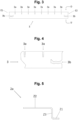
- Fig. 5 shows the Z-profile in side view with the first leg (Z1) at one end, the third leg (Z2) at the other end and the second leg (Z3) connecting them.
- Fig. 6 The press grate is shown in side view. It can be seen that the Z-profile (2a, 2b)) is arranged with its first leg (Z1) in the punching and is fixed there. The deformations (V) can be introduced into the long side both (in time) before and after connection to the cross member.
- Fig. 7 shows an enlarged section of the long side (2b) designed as a Z-profile Fig. 6 .
- FIG. 8 to 12 A second variant of the invention is shown, in which the subsequently introduced deformations are not shown.
- the longitudinal sides (2a, 2b) are designed in cross section as a polygonal profile (U0-U3), the polygonal profile (U0-U3) having a second leg (U3) arranged essentially parallel to the first leg (U0). comprising the connecting part (U1) connecting the first and the second leg and a third leg (U2) arranged substantially parallel to the connecting part (U1), the third leg (U2) being connected to the free end of the second leg.
- Punchings (3b) are provided at both ends (E1, E2) of the cross member (3), in which the first leg (U0) of the polygonal profile (U0-U3) is arranged.
- the punchings (3b), as shown, are essentially vertical cuts that extend from the underside of the cross member (3) towards the top.
- Fig. 11 is a detailed view of the cross member (3). Fig. 10 shown.
- Fig. 12 shows the polygonal profile in a side view with the first leg (U0), the essentially parallel second leg (U3), the connecting part (U1) connecting them, to which the third leg (U2) in turn runs parallel.
Landscapes
- Engineering & Computer Science (AREA)
- General Engineering & Computer Science (AREA)
- Mechanical Engineering (AREA)
- Incineration Of Waste (AREA)
- Rod-Shaped Construction Members (AREA)
- Assembled Shelves (AREA)
- Joining Of Building Structures In Genera (AREA)
- Connection Of Plates (AREA)
Description
- Die vorliegende Erfindung betrifft einen Preßrost, insbesondere für die Verwendung als Fachboden für Plattenregale oder Schwerlastregale, mit zwei Längsseiten und zwischen den Längsseiten angeordneten Querträgern und Längsträgern, wobei die Querträger und die Längsträger ein I-förmiges Profil aufweisen, wobei die Längsträger in zur Oberseite des Preßrostes offenen Stanzungen der Querträger eingesteckt oder eingepresst sind, wobei die Längsträger und die Querträger zueinander rechtwinklig angeordnet sind, und wobei die Längsseiten im Querschnitt als Profil ausgebildet sind, wobei das Profil der Längsseiten wenigstens einen ersten Schenkel und einen im Wesentlichen rechtwinklig zum ersten Schenkel angeordneten zweiten Schenkel umfasst, wobei jeder der Querträger an jedem Ende eine Stanzung aufweist, in welcher der erste Schenkel des Profils der Längsseiten angeordnet ist und über ein Verbindungsverfahren fest mit diesem verbunden ist.
- Wegen möglicher Brandgefahr in Lagerhallen werden Roste, die in Plattenregalen oder Schwerlastregalen angeordnet sind, für die Lagerung von Gütern verwendet. Diese Roste, wie beispielsweise in der
DE 80 14 894 U1 offenbart, weisen an ihren Längsseiten Profile auf, so daß sie auf Trägerbalken bzw. Holmen der Regale aufgenommen werden können. Zwischen den Längsseiten der Roste sind Längs- und Querstege angeordnet, auf denen die Güter gelagert werden. Durch die Ausgestaltung mit Längs- und Querstegen werden zudem Freiflächen gebildet, durch die im Falle eines Brandes Löschmedien (z.B. Löschwasser) von Sprinkleranlagen, die oftmals oberhalb der Roste angeordnet sind, durch die freien Flächen der Roste durchtreten können. Die Längs- und Querstege der Roste sind hierbei derart ausgestaltet, daß eine möglichst hohe Traglast der Roste erreicht wird und dennoch genügend Freiflächen für den Wasserdurchtritt gewährleitet werden können. Dementsprechend sind die Längsseiten und die Längs- und Querstege der vorbekannten Roste aus Stahlwerkstoffen hergestellt, die, um die gewünschte Stabilität und Traglast zu gewähren, nicht als Hohlkörper ausgebildet sind. - Nachteilig bei den oben beschriebenen Rosten ist, daß diese Roste, um hohe Traglasten zu gewähren, selbst ein hohes Eigengewicht aufweisen. Dementsprechend müssen die Plattenregale und Schwerlastregale derart konstruiert werden, daß sie neben den Gütern auch die Roste tragen können. Diese hochbeanspruchten Plattenregale und Schwerlastregale sind relativ teuer in der Anschaffung. Nachteilig ist weiterhin, daß hohe Materialkosten entstehen, um die gewünschte Traglast zu gewährleisten.
- Die
EP 1 559 346 A1 und dieDE 88 08 144 U1 offenbaren deswegen Regalroste, die zwei Längsseiten und zwischen den Längsseiten angeordnete Querträger aufweisen, wobei die Längsseiten im Querschnitt als offenes U-Profil ausgebildet sind. Die offenen Seiten der Querträger sind zur Unterseite des Rostes ausgerichtet. Jeder dieser Querträger weist an jedem Ende Aussparungen auf, die mit den Längsseiten über Stützleisten lösbar koppelbar sind. - Aus der
EP 1 457 618 A1 ist ein Gitterrost mit lang erstreckten Strukturbauteilen bekannt, wobei zumindest zwei einander gegenüber gelegene Endbereiche von Strukturbauteilen jeweils mit Haltekörpern in Verbindung stehen, die über auswärts greifende und zumindest eine Auflagefläche umfassende Bereiche an externen Widerlagern abstützbar sind, wobei Strukturbauteile mit in ihre stirnseitigen Enden hineinragenden Ausnehmungen versehen sind, die jeweils zumindest bereichsweise als im wesentlichen schlitzförmige Halteaufnahmen für ein in diese eingreifendes Halteglied eines Haltekörpers dienen, wobei der Abstand zwischen einander gegenüberliegenden und die Halteaufnahme begrenzenden Randkanten klein gegen die Längserstreckung des darin eingreifenden Halteglieds ist. - Die
DE 20 2016 104 526 U1 beschreibt eine Tragstruktur mit einem Gitterrost, der auf zumindest zwei gegenüberliegenden Trägern auflegbar ist, wobei der Gitterrost Tragstäbe und in einem Winkel dazu angeordnete und mit diesen verbundene Füllstäbe aufweist, dadurch gekennzeichnet, dass zumindest ein Tragstab mit zumindest einem Einhängewinkel in Eingriff ist, der einen Schenkel aufweist, der auf einen Träger auflegbar ist. - Aus der
DE 20 2009 015 918 U1 ist ein Regalboden-Grundträger für schwere Lasten bekannt, umfassend wenigstens zwei Querträger, die über eine Steckverbindung mit zwei spiegelbildlich zueinander ausgerichteten Auflagerprofilen zu verbinden sind, die jeweils wenigstens einen ersten horizontalen Profilschenkel zur Auflage auf einem Regalträger, einen vertikalen Profilschenkel und einen sich daran anschließenden zweiten horizontalen Profilabschnitt aufweisen. - Weiterhin werden von der Firma Gebr. Meiser GmbH U-Profil Regalroste angeboten, die zwei Längsseiten und zwischen den Längsseiten angeordneten Querträgern aufweisen, wobei die Längsseiten im Querschnitt als Profil ausgebildet sind, wobei das Profil wenigstens einen ersten Schenkel und einen im Wesentlichen rechtwinklig zum ersten Schenkel angeordneten zweiten Schenkel umfasst, wobei wenigstens zwei der Querträger im Querschnitt ein offenes Profil aufweisen, dessen offene Seite zur Unterseite des Rostes ausgerichtet ist, wobei jeder dieser Querträger an jedem Ende wenigstens eine Stanzung aufweist, wobei in jeder Stanzung der erste Schenkel des Profils angeordnet ist über einen stoffschlüssigen Fügeprozess, insbesondere ein Widerstandsschweißverfahren, fest mit diesem verbunden sind.
- Der eingesetzte Schweißprozess bedarf jedoch einer stetigen Überwachung und Regulierung der Schweißparameter im Fügeprozess, da sich jede Veränderung der Beschaffenheit der Ausgangsmaterialien als Störgröße im Prozess und in der Qualität des Fertigungsergebnisses widerspiegelt. Insbesondere muss die Überwachung und Regulierung der Schweißparameter im Fügeprozess dann erfolgen, wenn sehr dünne, aber auch unterschiedlich dicke Materialstärken, sowie vorbeschichtete Werkstoffe miteinander stoffschlüssig gefügt werden müssen. Würde eine stetige Überwachung und Regulierung der Schweißparameter im Fügeprozess nicht stattfinden, könnte die Haltbarkeit der Schweißnaht im Gebrauch beeinträchtigt werden, was zum Versagen der Schweißnaht und damit zur Destabilisierung des Regalrostes führen könnte.
- Der Erfindung liegt daher die Aufgabe zugrunde, einen Preßrost bereitzustellen, der leichter ist und günstiger bzw. weniger überwachungsintensiv in der Herstellung ist als der vorbekannte Stand der Technik, ohne die Baustabilität und Tragfähigkeit zu beeinträchtigen.
- Die Aufgabe der Erfindung wird durch einen Preßrost gemäß dem Oberbegriff dadurch gelöst, daß durch das nachträgliche Einbringen von Verformungen jeweils rechts und links vom Querträger, bevorzugt unmittelbar neben demselben, in den ersten Schenkel des Profils der Längsseiten ein horizontales Verschieben der Bauteile gegeneinander verhindert ist, wodurch eine Fixierung der Steck- oder Pressverbindung des Querträgers mit dem Profil der Längsseiten erreicht wird.
- Auf diese Weise läßt sich schnell und wirtschaftlich ein äußerst stabiler Preßrost fertigen.
- Da mehrere dieser Roste als Fachböden in Plattenregalen oder Schwerlastregalen angeordnet werden, kann durch eine Gewichtsreduktion der Roste eine Kostenreduktion in der Regalkonstruktion erreicht werden, da diese, bei gleichbleibender Stabilität, weniger Last tragen müssen, wodurch die Materialkosten (zum Erreichen dieser Stabilität) für die Regale gesenkt werden können.
- Da der Schenkel des Profils in der Stanzung des Querträgers eingesteckt oder eingepresst ist, wird eine Fixierung des Profils mit dem Querträger erreicht. Eine Sicherung gegen ein Verschieben der Bauteile (Profil und Querträger) gegeneinander, wird durch ein weiteres Verbindungsverfahren, nämlich ein form- und/oder kraftschlüssiges Verbindungsverfahren, erreicht, im Rahmen dessen die Verformung erfolgt.
- Eine Prägung ist hierbei eine mit Druck, Tiefziehen oder Prägewerkzeug in den Schenkel eingebrachte Verformung.
- Vorteilhafterweise ist die Verformung bzw. sind die Verformungen in unmittelbarer Nähe bzw. direkt neben der Steck- bzw. Pressverbindung des Querträgers mit dem Profil angeordnet. Es ist ebenfalls vorteilhaft vorgesehen, daß wenigstens zwei Verformungen in dem Profil beidseitig jeweils in der Nähe bzw. direkt neben der Steck- bzw. Pressverbindung angeordnet sind, so daß die Steck- bzw. Pressverbindung des Querträgers mit dem Profil beidseitig fixiert ist.
- Eine bevorzugte Ausgestaltung der Erfindung sieht vor, daß das Profil als Z-Profil, als L-Profil oder als Mehrkantprofil ausgebildet ist, wobei das Z-Profil einen zum ersten Schenkel im Wesentlichen parallel angeordneten zweiten Schenkel umfasst, wobei das Verbindungsteil den ersten und den dritten Schenkel verbindet, das L-Profil einen ersten Schenkel und einen im Wesentlichen rechtwinklig zum ersten Schenkel angeordneten zweiten Schenkel umfasst und das Mehrkantprofil einen zum ersten Schenkel im Wesentlichen parallel angeordneten zweiten Schenkel, das den ersten und den zweiten Schenkel verbindende Verbindungsteil sowie einen zum Verbindungsteil im Wesentlichen parallel angeordneten dritten Schenkel umfasst, wobei der dritte Schenkel mit dem freien Ende des zweiten Schenkels verbunden ist.
- Es ist zu der Erfindung gehörig, daß der Preßrost aus Stahl, vorzugsweise vorverzinktem Stahl, Edelstahl oder Aluminium besteht.
- Hierbei kann vorteilhaft vorgesehen sein, daß der Rost aus Stahl besteht, wobei der Stahl ein vorverzinkter Stahl ist.
- Eine weitere Ausgestaltung der Erfindung sieht vorteilhaft vor, daß die Oberflächen der Längsseiten und der Querträger mit einem Beschichtungsmaterial beschichtet sind, wobei das Beschichtungsmaterial die Oberflächen vor Korrosion schützt und/oder feuerabweisend wirkt.
- Es liegt im Rahmen der Erfindung, daß das Verhältnis der Traglast des Preßrostes zu dem Eigengewicht des Preßrostes im Bereich von 10 bis 200 liegt.
- Damit besitzt der erfindungsgemäße Rost eine Tragkraft, die das 10-fache bis 200-fache des Eigengewichts aufweist.
- Weiterhin ist es bevorzugt, daß wenigstens 70 % der von dem Preßrost abgedeckten Fläche als freie Projektionsfläche ausgestaltet ist.
- Diese Ausgestaltung ist insbesondere vorteilhaft, um im Falle eines Brandes den Abschattungseffekt des Rostes (der aus Querträgern und Längsseiten besteht) so gering wie möglich zu gestalten, so daß Löschmedien von Sprinkleranlagen durch die freien Projektionsflächen (Durchtrittsflächen) des Rostes durchtreten können.
- Es ist vorteilhaft, daß wenigstens eine der Stanzungen am jeweiligen Ende eines Querträgers eine Einlaufkontur mit wenigstens einer Schikane aufweist, wodurch ein zentriertes Einführen und ein kraft- und/oder formschlüssiges Verbinden des ersten Schenkels des Profils mit dem Querträger ermöglicht wird.
- Bei dieser Ausgestaltung der Erfindung ist es vorteilhaft, daß die wenigstens eine Stanzung am jeweiligen Ende des Querträgers keilförmig ausgebildet ist.
- Im Rahmen der Erfindung liegt auch ein Verfahren zum Herstellen eines Preßrostes, insbesondere für die Verwendung als Fachboden für Plattenregale oder Schwerlastregale, mit zwei Längsseiten und zwischen den Längsseiten angeordneten Querträgern und Längsträgern, wobei die Querträger und die Längsträger ein I-förmiges Profil aufweisen, wobei die Längsträger in zur Oberseite des Preßrostes offenen Stanzungen der Querträger eingesteckt oder eingepresst werden, wobei die Längsträger und die Querträger zueinander rechtwinklig angeordnet werden, und wobei die Längsseiten im Querschnitt als Profil ausgebildet sind, wobei das Profil der Längsseiten wenigstens einen ersten Schenkel und ein im Wesentlichen rechtwinklig zum ersten Schenkel angeordneten zweiten Schenkel umfasst, wobei jeder der Querträger an jedem Ende eine Stanzung aufweist, in welcher der erste Schenkel des Profils der Längsseiten angeordnet wird und über ein Verbindungsverfahren fest mit diesem verbunden wird, wobei in einem ersten Schritt der erste Schenkel des Profils der Längsseiten in die Stanzung eingesteckt oder eingepresst wird, wodurch eine erste Verbindung des Profils der Längsseiten mit dem Querträger erreicht wird, und nachträgliche Verformungen jeweils rechts und links vom Querträger, bevorzugt unmittelbar neben demselben, in den ersten Schenkel des Profils der Längsseiten eingebracht werden, wodurch ein horizontales Verschieben der Bauteile gegeneinander verhindert wird, so daß eine Fixierung der Steck- oder Pressverbindung des Querträgers mit dem Profil der Längsseiten erreicht wird.
- Nachfolgend werden Ausführungsbeispiele der Erfindung anhand von Zeichnungen näher, aber nicht darauf beschränkt, erläutert. Es zeigen
- Fig. 1
- eine erste Variante des erfindungsgemäßen Preßrostes in perspektivischer Ansicht,
- Fig. 2
- eine Detailansicht zu
Fig. 1 , - Fig. 3
- eine Seitenansicht des Querträgers,
- Fig. 4
- eine Detailansicht zu
Fig. 2 , - Fig. 5
- das Profil in Seitenansicht,
- Fig. 6
- den Preßrost in Seitenansicht,
- Fig. 7
- eine Detailansicht zu
Fig. 6 , - Fig. 8
- eine zweite Variante des erfindungsgemäßen Preßrostes, bei der die nachträglich eingebrachten Verformungen nicht gezeigt sind, in perspektivischer Ansicht,
- Fig. 9
- eine Detailansicht zu
Fig. 8 , - Fig. 10
- eine Seitenansicht des Querträgers,
- Fig. 11
- eine Detailansicht zu
Fig. 10 , - Fig. 12
- das Profil in Seitenansicht.
- In den
Fig. 1 bis 7 ist eine erste Variante des erfindungsgemäßen Rostes (1) mit zwei Längsseiten (2a, 2b) und zwischen den Längsseiten (2a, 2b) angeordneten Querträgern (3-) in perspektivischer Ansicht dargestellt. Die Längsseiten (2a, 2b) sind im Querschnitt als Z-Profil ausgebildet, wobei das Z-Profil einen ersten Schenkel (Z1), einen zum ersten Schenkel im Wesentlichen parallel angeordneten dritten Schenkel (Z2) umfasst, wobei der zweite Schenkel (Z3) den ersten und den dritten Schenkel verbindet. Die Querträger (3) weisen im Querschnitt ein I-förmiges Profil auf. - In
Fig. 2 ist die Verbindung eines Querträgers (3) mit einer Längsseite (2a), die im Querschnitt als Z-Profil ausgebildet ist, in perspektivischer Ansicht vergrößert dargestellt. Wie dargestellt, ist der erste Schenkel (Z1) des Z-Profils an einem Ende (E1) des Querträgers in dessen Stanzungen (3b) eingesteckt bzw. eingepresst. Da der Querträger (3) im Querschnitt I-förmig ausgestaltet ist, weist der Querträger (3) an jedem Ende zwei Stanzungen (3b) auf. Die Stanzungen (3b) weisen vorzugsweise eine Schikane auf und/oder sind keilförmig ausgebildet. Durch das Einstecken oder Einpressen des ersten Schenkels (Z1) des Z-Profils in die Stanzungen (3b) des Querträgers (3) wird erreicht, daß eine Fixierung der Bauteile (Querträger und Längsseite) gegeneinander erfolgt. Durch das nachträgliche Einbringen von Verformungen (V1, V3) jeweils rechts und links vom Querträger (3), bevorzugt unmittelbar neben demselben, in den ersten Schenkel (Z1) des Profils wird zum einen ein horizontales Verschieben der Bauteile gegeneinander verhindert und weiterhin erreicht, daß durch das nachträgliche Verformen des ersten Schenkels (Z1) der erste Schenkel (Z1) im Bereich der Stanzung (3b) vertikal in der Stanzung (3b) verformt bzw. verkeilt wird. Letzteres verhindert ein Herausziehen des ersten Schenkels (Z1) aus den Stanzungen (3b) des Querträgers. - In
Fig. 3 ist ein im Querschnitt I-förmiger Querträger, der an jedem Ende (E1, E2) wenigstens zwei Stanzungen (3b) aufweist, in perspektivischer Ansicht dargestellt. Es ist vorgesehen, daß wenigstens eine der Stanzungen (3b) an dem jeweiligen Ende (E1, E2) keilförmig ausgebildet ist. -
Fig. 4 zeigt einen vergrößerten Ausschnitt des I-förmigen Querträgers (3) ausFig. 3 mit einer schikanenförmigen Stanzung (3b) an dem vergrößerten Ende (E2). -
Fig. 5 zeigt das Z-Profil in Seitenansicht mit dem ersten Schenkel (Z1) an dem einen Ende, dem dritten Schenkel (Z2) an dem anderen Ende und dem diese verbindenden zweiten Schenkel (Z3). - In
Fig. 6 ist der Preßrost in Seitenansicht dargestellt. Es ist zu erkennen, daß das Z-Profil (2a, 2b)) mit seinem ersten Schenkel (Z1) in der Stanzung angeordnet und dort festgelegt ist. Die Verformungen (V) können sowohl (zeitlich) vor als auch nach dem Verbinden mit dem Querträger in die Längsseite eingebracht sein. -
Fig. 7 zeigt einen vergrößerten Ausschnitt der als Z-Profil ausgebildeten Längsseite (2b) ausFig. 6 . - In den
Fig. 8 bis 12 ist eine zweite Variante der Erfindung dargestellt, bei der die nachträglich eingebrachten Verformungen nicht gezeigt sind. Bei dieser Variante sind die Längsseiten (2a, 2b) im Querschnitt als Mehrkant-Profil (U0-U3) ausgebildet, wobei das Mehrkantprofil (U0-U3) einen zum ersten Schenkel (U0) im Wesentlichen parallel angeordneten zweiten Schenkel (U3), ein den ersten und den zweiten Schenkel verbindendes Verbindungsteil (U1) sowie einen zum Verbindungsteil (U1) im Wesentlichen parallel angeordneten dritten Schenkel (U2) umfasst, wobei der dritte Schenkel (U2) mit dem freien Ende des zweiten Schenkels verbunden ist. An beiden Enden (E1, E2) des Querträgers (3) sind Stanzungen (3b) vorgesehen, in denen der erste Schenkel (U0) des Mehrkant-Profils (U0-U3) angeordnet wird. Die Stanzungen (3b) sind, wie dargestellt, als im Wesentlichen vertikale Einschnitte, die sich von der Unterseite des Querträgers (3) in Richtung zu dessen Oberseite erstrecken. - In
Fig. 11 ist eine Detailansicht des Querträgers (3) ausFig. 10 dargestellt. -
Fig. 12 zeigt das Mehrkant-Profil in Seitenansicht mit dem ersten Schenkel (U0), dem dazu im Wesentlichen parallelen zweiten Schenkel (U3), dem diese verbindenden Verbindungsteil (U1), zu dem wiederum der dritte Schenkel (U2) parallel verläuft. - Hinsichtlich weiterer, in den Figuren nicht gezeigter Merkmale wird auf den allgemeinen Teil der Beschreibung verwiesen.
-
- 1
- Rost
- 2a, 2b
- Längsseiten
- 3
- Querträger
- 3a
- zur Oberseite des Querträgers offene Stanzungen
- 3b
- Stanzungen am Ende des Querträgers
- 4
- Längsträger
- Z1
- erster Schenkel
- Z2
- dritter Schenkel
- Z3
- zweiter Schenkel
- V1, V2
- Verformungen
- E1, E2
- Ende des Querträgers
- U0-U3
- Mehrkantprofil
- UO
- erster Schenkel
- U1
- Verbindungsteil
- U2
- dritter Schenkel
- U3
- zweiter Schenkel
Claims (8)
- Preßrost (1), insbesondere für die Verwendung als Fachboden für Plattenregale oder Schwerlastregale, mit zwei Längsseiten (2a, 2b) und zwischen den Längsseiten (2a, 2b) angeordneten Querträgern (3) und Längsträgern (4), wobei die Querträger (3) und die Längsträger (4) ein I-förmiges Profil aufweisen, wobei die Längsträger (4) in zur Oberseite des Preßrostes (1) offenen Stanzungen (3a) der Querträger eingesteckt oder eingepresst sind, wobei die Längsträger (4) und die Querträger (3) zueinander rechtwinklig angeordnet sind, und wobei die Längsseiten (2a, 2b) im Querschnitt als Profil (Z1-Z3; U0-U3) ausgebildet sind, wobei das Profil (Z1-Z3; U0-U3) der Längsseiten (2a, 2b) wenigstens einen ersten Schenkel (Z1; U0) und einen im Wesentlichen rechtwinklig zum ersten Schenkel (Z1; U0) angeordneten zweiten Schenkel (Z3; U3 ) umfasst, wobei jeder der Querträger (3) an jedem Ende (E1, E2) eine Stanzung (3b) aufweist, in welcher der erste Schenkel (Z1; U0) des Profils (Z1-Z3; U0-U3) angeordnet ist und über ein Verbindungsverfahren fest mit diesem verbunden ist, wobei der erste Schenkel (Z1; U0) des Profils (Z1-Z3; U0-U3) der Längsseiten (2a, 2b) in die Stanzung (3b) eingesteckt oder eingepresst ist, wodurch eine erste Verbindung des Profils (Z1-Z3; U0-U3) der Längsseiten (2a, 2b) mit dem Querträger erreicht wird, dadurch gekennzeichnet, daß durch das nachträgliche Einbringen von Verformungen (V1, V3) jeweils rechts und links vom Querträger, bevorzugt unmittelbar neben demselben, in den ersten Schenkel (Z1, U0) des Profils (Z1-Z3; U0-U3) der Längsseiten (2a, 2b) ein horizontales Verschieben der Bauteile gegeneinander verhindert ist, wodurch eine Fixierung der Steck- oder Pressverbindung des Querträgers mit dem Profil (Z1-Z3; U0-U3) der Längsseiten (2a, 2b) erreicht wird.
- Preßrost (1) gemäß Anspruch 1, dadurch gekennzeichnet, daß das Profil (Z1-Z3; U0-U3) der Längsseiten (2a, 2b) als Z-Profil (Z1-Z3), als L-Profil oder als Mehrkantprofil (U0-U3) ausgebildet ist, wobei das Z-Profil einen zum ersten Schenkel (Z1) im Wesentlichen parallel angeordneten dritten Schenkel (Z2) umfasst, wobei der zweite Schenkel (Z3) den ersten Schenkel (Z1) und den dritten Schenkel (Z2) verbindet, das L-Profil einen ersten Schenkel und einen im Wesentlichen rechtwinklig zum ersten Schenkel angeordneten zweiten Schenkel umfasst und das Mehrkantprofil (U0-U3) einen zum ersten Schenkel (U0) im Wesentlichen parallel angeordneten zweiten Schenkel (U3), ein den ersten und den zweiten Schenkel verbindendes Verbindungsteil (U1) sowie einen zum Verbindungsteil (U1) im Wesentlichen parallel angeordneten dritten Schenkel (U2) umfasst, wobei der dritte Schenkel (U2) mit dem freien Ende des zweiten Schenkels (U3) verbunden ist.
- Preßrost (1) gemäß einem der vorhergehenden Ansprüche, dadurch gekennzeichnet, daß der Preßrost (1) aus Stahl, vorzugsweise vorverzinktem Stahl, Edelstahl oder Aluminium besteht.
- Preßrost (1) gemäß einem der vorhergehenden Ansprüche, dadurch gekennzeichnet, daß das Verhältnis der Traglast des Preßrostes (1) zu dem Eigengewicht des Preßrostes (1) im Bereich von 10 bis 200 liegt.
- Preßrost (1) gemäß einem der vorhergehenden Ansprüche, dadurch gekennzeichnet, daß wenigstens 70 % der von dem Preßrost (1) abgedeckten Fläche als freie Projektionsfläche ausgestaltet ist.
- Preßrost (1) gemäß Anspruch 1, dadurch gekennzeichnet, daß wenigstens eine der Stanzungen (3b) am jeweiligen Ende (E1; E2) eines Querträgers eine Einlaufkontur mit wenigstens einer Schikane aufweist, wodurch ein zentriertes Einführen und ein kraft- und/oder formschlüssiges Verbinden des ersten Schenkels (Z1; U0) des Profils (Z1-Z3; U0-U3) mit dem Querträger ermöglicht wird.
- Preßrost (1) gemäß Anspruch 6, dadurch gekennzeichnet, daß die wenigstens eine Stanzung (3b) am jeweiligen Ende (E1; E2) des Querträgers keilförmig ausgebildet ist.
- Verfahren zum Herstellen eines Preßrostes (1), insbesondere für die Verwendung als Fachboden für Plattenregale oder Schwerlastregale, mit zwei Längsseiten (2a, 2b) und zwischen den Längsseiten (2a, 2b) angeordneten Querträgern (3) und Längsträgern (4), wobei die Querträger (3) und die Längsträger (4) ein I-förmiges Profil aufweisen, wobei die Längsträger (4) in zur Oberseite des Preßrostes (1) offenen Stanzungen (3a) der Querträger eingesteckt oder eingepresst werden, wobei die Längsträger (4) und die Querträger (3) zueinander rechtwinklig angeordnet werden, und wobei die Längsseiten (2a, 2b) im Querschnitt als Profil (Z1-Z3; U0-U3) ausgebildet sind, wobei das Profil (Z1-Z3; U0-U3) der Längsseiten (2a, 2b) wenigstens einen ersten Schenkel (Z1; U0) und einen im Wesentlichen rechtwinklig zum ersten Schenkel (Z1; U0) angeordneten zweiten Schenkel (Z3; U3 ) umfasst, wobei jeder der Querträger (3) an jedem Ende (E1, E2) eine Stanzung (3b) aufweist, in welcher der erste Schenkel (Z1; U0) des Profils (Z1-Z3; U0-U3) angeordnet wird und über ein Verbindungsverfahren fest mit diesem verbunden wird, wobei in einem ersten Schritt der erste Schenkel (Z1; U0) des Profils (Z1-Z3; U0-U3) der Längsseiten (2a, 2b) in die Stanzung (3b) eingesteckt oder eingepresst wird, wodurch eine erste Verbindung des Profils (Z1-Z3; U0-U3) der Längsseiten (2a, 2b) mit dem Querträger (3) erreicht wird, dadurch gekennzeichnet, daß nachträgliche Verformungen (V1, V3) jeweils rechts und links vom Querträger (3), bevorzugt unmittelbar neben demselben, in den ersten Schenkel (Z1; U0) des Profils (Z1-Z3; U0-U3) der Längsseiten (2a, 2b) eingebracht werden, wodurch ein horizontales Verschieben der Bauteile gegeneinander verhindert wird, so daß eine Fixierung der Steck- oder Pressverbindung des Querträgers mit dem Profil (Z1-Z3; U0-U3) der Längsseiten (2a, 2b) erreicht wird.
Applications Claiming Priority (2)
| Application Number | Priority Date | Filing Date | Title |
|---|---|---|---|
| DE202018103893.1U DE202018103893U1 (de) | 2018-07-06 | 2018-07-06 | Preßrost |
| PCT/DE2019/100420 WO2020007390A1 (de) | 2018-07-06 | 2019-05-09 | PREßROST |
Publications (3)
| Publication Number | Publication Date |
|---|---|
| EP3817626A1 EP3817626A1 (de) | 2021-05-12 |
| EP3817626B1 true EP3817626B1 (de) | 2024-03-27 |
| EP3817626C0 EP3817626C0 (de) | 2024-03-27 |
Family
ID=63045687
Family Applications (1)
| Application Number | Title | Priority Date | Filing Date |
|---|---|---|---|
| EP19726562.2A Active EP3817626B1 (de) | 2018-07-06 | 2019-05-09 | Pressrost |
Country Status (5)
| Country | Link |
|---|---|
| US (1) | US11612245B2 (de) |
| EP (1) | EP3817626B1 (de) |
| DE (1) | DE202018103893U1 (de) |
| ES (1) | ES2980186T3 (de) |
| WO (1) | WO2020007390A1 (de) |
Families Citing this family (5)
| Publication number | Priority date | Publication date | Assignee | Title |
|---|---|---|---|---|
| US11369215B2 (en) | 2018-12-17 | 2022-06-28 | Fasteners For Retail, Inc. | Retail shelving system |
| EP3922140A3 (de) | 2020-04-23 | 2022-02-16 | Fasteners for Retail, Inc. | Warenregalsystem für den einzelhandel |
| US12053106B2 (en) * | 2020-05-28 | 2024-08-06 | Fasteners For Retail, Inc. | Retail merchandise shelving system and deck panels for same |
| US12534899B2 (en) * | 2022-12-09 | 2026-01-27 | Midwest Design Group | Trench drains with suspended grates |
| US12546102B2 (en) * | 2023-02-23 | 2026-02-10 | Advanced Drainage Systems, Inc. | Linear or trench drain systems |
Family Cites Families (30)
| Publication number | Priority date | Publication date | Assignee | Title |
|---|---|---|---|---|
| US1184309A (en) * | 1913-05-16 | 1916-05-23 | Nathan Berson | Ventilating-grating. |
| US1426736A (en) * | 1921-02-10 | 1922-08-22 | William H Hess | Grating |
| US1428230A (en) * | 1921-04-30 | 1922-09-05 | William H Hess | Grating |
| US2031779A (en) * | 1933-06-29 | 1936-02-25 | Walter P Ladd | Grating and method of making same |
| US2084118A (en) * | 1934-03-05 | 1937-06-15 | Gabriel Steel Company | Grating |
| US3469359A (en) * | 1965-07-13 | 1969-09-30 | Reliance Steel Products Co | Friction locked grating and other open grid structures |
| US3645510A (en) * | 1970-03-04 | 1972-02-29 | Ceilcote Co Inc | Grid member and wall formed therefrom |
| SE382337B (sv) * | 1972-09-12 | 1976-01-26 | E Arens | Galler |
| CH575058A5 (de) * | 1974-03-12 | 1976-04-30 | Wyss Otto | |
| US4067094A (en) * | 1976-04-26 | 1978-01-10 | Harry Feick Co., Inc. | Load bearing vane structure for thrust reversal |
| DE8014894U1 (de) | 1980-06-04 | 1987-12-03 | Jürgens, Walter, Dr.-Ing., 5100 Aachen | Schwerlastregal |
| US4727704A (en) * | 1987-05-07 | 1988-03-01 | Fibergrate Corporation | Grating structure and method for assembly |
| DE8808144U1 (de) | 1988-06-24 | 1988-08-18 | Meta-Regalbau Gmbh & Co Kg, 5760 Arnsberg | Faßauflage für die in Regalständern hängenden vorderen und hinteren Stufenholme |
| US4903444A (en) * | 1988-10-03 | 1990-02-27 | Berndt Jr Fred P | Floor grating |
| US5024550A (en) * | 1989-09-26 | 1991-06-18 | Jack Mainville | Trench grate |
| US5203544A (en) * | 1991-07-09 | 1993-04-20 | Webb A Levan | Cattle guard |
| USD374727S (en) * | 1992-06-09 | 1996-10-15 | IMC/Teddy Food Service Corp. | Floor grate |
| US5771647A (en) * | 1996-09-27 | 1998-06-30 | Carnes Company, Inc. | Grille assembly and related method |
| US5865007A (en) * | 1997-10-27 | 1999-02-02 | Composite Structures International, Inc. | Integrally molded reinforced grating |
| USD410709S (en) * | 1998-03-11 | 1999-06-08 | Kadee Quality Products Co. | Roof walk for model railway car |
| DE20302998U1 (de) | 2003-02-25 | 2003-04-30 | Steggemann, Franz, 48703 Stadtlohn | Gitterrost |
| EP1559346B1 (de) | 2004-01-28 | 2006-06-14 | Stow International N.V. | Lagersystem und Komponenten dafür |
| US6908256B1 (en) * | 2004-06-23 | 2005-06-21 | Aco Polymer Products, Inc. | Drainage grate assembly |
| US8132385B2 (en) * | 2005-01-13 | 2012-03-13 | Southwest Agri-Plastic, Inc. | Benchtop panels |
| DE102006051160A1 (de) * | 2006-10-30 | 2008-05-08 | Aco Severin Ahlmann Gmbh & Co. Kg | Abdeckrost |
| DE202009015918U1 (de) | 2009-11-23 | 2010-03-04 | Gi-Ro Technik Gmbh & Co. Kg | Regalboden-Grundträger |
| DE102010037563B4 (de) * | 2010-08-19 | 2012-10-04 | Aco Severin Ahlmann Gmbh & Co. Kg | Abdeckung für Rinnen, Schächte oder dergleichen Bauwerke |
| DE102015108298B4 (de) * | 2015-05-26 | 2021-06-10 | Gi-Ro Technik Gmbh & Co. Kg | Steckbarer Gitterrost und Verfahren zu seiner Herstellung |
| DE202016104526U1 (de) | 2016-08-18 | 2016-09-01 | Mea Metal Applications Gmbh | Tragstruktur |
| DE202017103028U1 (de) | 2017-05-19 | 2018-08-21 | Gi-Ro Technik Gmbh & Co. Kg | Selbsttragendes Gitterbodenelement für Warenlagerregale und Laufgänge |
-
2018
- 2018-07-06 DE DE202018103893.1U patent/DE202018103893U1/de not_active Expired - Lifetime
-
2019
- 2019-05-09 WO PCT/DE2019/100420 patent/WO2020007390A1/de not_active Ceased
- 2019-05-09 US US17/257,930 patent/US11612245B2/en active Active
- 2019-05-09 EP EP19726562.2A patent/EP3817626B1/de active Active
- 2019-05-09 ES ES19726562T patent/ES2980186T3/es active Active
Also Published As
| Publication number | Publication date |
|---|---|
| DE202018103893U1 (de) | 2018-07-16 |
| US20210282553A1 (en) | 2021-09-16 |
| EP3817626C0 (de) | 2024-03-27 |
| EP3817626A1 (de) | 2021-05-12 |
| ES2980186T3 (es) | 2024-09-30 |
| US11612245B2 (en) | 2023-03-28 |
| WO2020007390A1 (de) | 2020-01-09 |
Similar Documents
| Publication | Publication Date | Title |
|---|---|---|
| EP3817626B1 (de) | Pressrost | |
| EP4039131B1 (de) | Regalsystem | |
| DE102010038968B4 (de) | Regal mit Traversen | |
| EP2010023B1 (de) | Regal-fachboden | |
| DE29914351U1 (de) | Regal | |
| DE9106686U1 (de) | Ständer zur Aufnahme von Kassetten, insbesondere CD-Kassetten | |
| DE102024114724A1 (de) | Gitterrost für eine Regalanlage in einem Warenlager | |
| EP3307653B1 (de) | Roste, insbesondere für die verwendung als fachboden für plattenregale oder schwerlastregale | |
| DE102017216892A1 (de) | Gerüstelement zur Anbindung an eine scheibenförmige Anschlussplatte sowie Gerüst-Teil mit einem solchen Gerüstelement | |
| DE69226207T2 (de) | Verbesserungen an regalen | |
| DE20302998U1 (de) | Gitterrost | |
| EP3372451B1 (de) | Dachlager für einen dachträger in leichtbauweise | |
| EP0935932B1 (de) | Lagerregal, vorzugsweise für die Lagerung bestückter Paletten | |
| EP2934237B1 (de) | Hakenteil | |
| DE2507298C2 (de) | Lagerregal mit an ihren Frontseiten und Stirnseiten abgekanteten Fachböden aus Blech | |
| DE29519639U1 (de) | Regal und Kragarm zu dessen Herstellung | |
| DE3878214T2 (de) | Metallisches regal. | |
| EP4403491B1 (de) | Regalsystemverbinder | |
| EP0976666B1 (de) | Halterung für Lagerstangen | |
| DE60013058T2 (de) | Senkrechtes Lager | |
| DE9400159U1 (de) | Palettenregal | |
| DE9209912U1 (de) | Trittplatte für Leitern | |
| DE3035501A1 (de) | Regal, insbesondere gondel fuer einen laden o.dgl. | |
| DE2446797A1 (de) | Profilstab fuer ein regal und daraus hergestelltes regal | |
| DE29802698U1 (de) | Stranggezogene C-Profilschiene für rahmenartige Tragsysteme |
Legal Events
| Date | Code | Title | Description |
|---|---|---|---|
| STAA | Information on the status of an ep patent application or granted ep patent |
Free format text: STATUS: THE INTERNATIONAL PUBLICATION HAS BEEN MADE |
|
| PUAI | Public reference made under article 153(3) epc to a published international application that has entered the european phase |
Free format text: ORIGINAL CODE: 0009012 |
|
| STAA | Information on the status of an ep patent application or granted ep patent |
Free format text: STATUS: REQUEST FOR EXAMINATION WAS MADE |
|
| 17P | Request for examination filed |
Effective date: 20201218 |
|
| AK | Designated contracting states |
Kind code of ref document: A1 Designated state(s): AL AT BE BG CH CY CZ DE DK EE ES FI FR GB GR HR HU IE IS IT LI LT LU LV MC MK MT NL NO PL PT RO RS SE SI SK SM TR |
|
| DAV | Request for validation of the european patent (deleted) | ||
| DAX | Request for extension of the european patent (deleted) | ||
| GRAP | Despatch of communication of intention to grant a patent |
Free format text: ORIGINAL CODE: EPIDOSNIGR1 |
|
| STAA | Information on the status of an ep patent application or granted ep patent |
Free format text: STATUS: GRANT OF PATENT IS INTENDED |
|
| INTG | Intention to grant announced |
Effective date: 20211102 |
|
| GRAJ | Information related to disapproval of communication of intention to grant by the applicant or resumption of examination proceedings by the epo deleted |
Free format text: ORIGINAL CODE: EPIDOSDIGR1 |
|
| STAA | Information on the status of an ep patent application or granted ep patent |
Free format text: STATUS: REQUEST FOR EXAMINATION WAS MADE |
|
| INTC | Intention to grant announced (deleted) | ||
| GRAP | Despatch of communication of intention to grant a patent |
Free format text: ORIGINAL CODE: EPIDOSNIGR1 |
|
| STAA | Information on the status of an ep patent application or granted ep patent |
Free format text: STATUS: GRANT OF PATENT IS INTENDED |
|
| INTG | Intention to grant announced |
Effective date: 20220208 |
|
| GRAJ | Information related to disapproval of communication of intention to grant by the applicant or resumption of examination proceedings by the epo deleted |
Free format text: ORIGINAL CODE: EPIDOSDIGR1 |
|
| STAA | Information on the status of an ep patent application or granted ep patent |
Free format text: STATUS: REQUEST FOR EXAMINATION WAS MADE |
|
| GRAP | Despatch of communication of intention to grant a patent |
Free format text: ORIGINAL CODE: EPIDOSNIGR1 |
|
| STAA | Information on the status of an ep patent application or granted ep patent |
Free format text: STATUS: GRANT OF PATENT IS INTENDED |
|
| INTC | Intention to grant announced (deleted) | ||
| GRAJ | Information related to disapproval of communication of intention to grant by the applicant or resumption of examination proceedings by the epo deleted |
Free format text: ORIGINAL CODE: EPIDOSDIGR1 |
|
| INTG | Intention to grant announced |
Effective date: 20220706 |
|
| STAA | Information on the status of an ep patent application or granted ep patent |
Free format text: STATUS: REQUEST FOR EXAMINATION WAS MADE |
|
| INTC | Intention to grant announced (deleted) | ||
| GRAP | Despatch of communication of intention to grant a patent |
Free format text: ORIGINAL CODE: EPIDOSNIGR1 |
|
| STAA | Information on the status of an ep patent application or granted ep patent |
Free format text: STATUS: GRANT OF PATENT IS INTENDED |
|
| INTG | Intention to grant announced |
Effective date: 20220914 |
|
| GRAJ | Information related to disapproval of communication of intention to grant by the applicant or resumption of examination proceedings by the epo deleted |
Free format text: ORIGINAL CODE: EPIDOSDIGR1 |
|
| STAA | Information on the status of an ep patent application or granted ep patent |
Free format text: STATUS: REQUEST FOR EXAMINATION WAS MADE |
|
| STAA | Information on the status of an ep patent application or granted ep patent |
Free format text: STATUS: EXAMINATION IS IN PROGRESS |
|
| INTC | Intention to grant announced (deleted) | ||
| 17Q | First examination report despatched |
Effective date: 20230130 |
|
| GRAP | Despatch of communication of intention to grant a patent |
Free format text: ORIGINAL CODE: EPIDOSNIGR1 |
|
| STAA | Information on the status of an ep patent application or granted ep patent |
Free format text: STATUS: GRANT OF PATENT IS INTENDED |
|
| INTG | Intention to grant announced |
Effective date: 20231116 |
|
| GRAS | Grant fee paid |
Free format text: ORIGINAL CODE: EPIDOSNIGR3 |
|
| GRAA | (expected) grant |
Free format text: ORIGINAL CODE: 0009210 |
|
| STAA | Information on the status of an ep patent application or granted ep patent |
Free format text: STATUS: THE PATENT HAS BEEN GRANTED |
|
| AK | Designated contracting states |
Kind code of ref document: B1 Designated state(s): AL AT BE BG CH CY CZ DE DK EE ES FI FR GB GR HR HU IE IS IT LI LT LU LV MC MK MT NL NO PL PT RO RS SE SI SK SM TR |
|
| REG | Reference to a national code |
Ref country code: GB Ref legal event code: FG4D Free format text: NOT ENGLISH |
|
| REG | Reference to a national code |
Ref country code: CH Ref legal event code: EP |
|
| REG | Reference to a national code |
Ref country code: DE Ref legal event code: R096 Ref document number: 502019010901 Country of ref document: DE |
|
| REG | Reference to a national code |
Ref country code: IE Ref legal event code: FG4D Free format text: LANGUAGE OF EP DOCUMENT: GERMAN |
|
| U01 | Request for unitary effect filed |
Effective date: 20240417 |
|
| U07 | Unitary effect registered |
Designated state(s): AT BE BG DE DK EE FI FR IT LT LU LV MT NL PT SE SI Effective date: 20240424 |
|
| PG25 | Lapsed in a contracting state [announced via postgrant information from national office to epo] |
Ref country code: GR Free format text: LAPSE BECAUSE OF FAILURE TO SUBMIT A TRANSLATION OF THE DESCRIPTION OR TO PAY THE FEE WITHIN THE PRESCRIBED TIME-LIMIT Effective date: 20240628 |
|
| U20 | Renewal fee for the european patent with unitary effect paid |
Year of fee payment: 6 Effective date: 20240613 |
|
| PG25 | Lapsed in a contracting state [announced via postgrant information from national office to epo] |
Ref country code: HR Free format text: LAPSE BECAUSE OF FAILURE TO SUBMIT A TRANSLATION OF THE DESCRIPTION OR TO PAY THE FEE WITHIN THE PRESCRIBED TIME-LIMIT Effective date: 20240327 Ref country code: RS Free format text: LAPSE BECAUSE OF FAILURE TO SUBMIT A TRANSLATION OF THE DESCRIPTION OR TO PAY THE FEE WITHIN THE PRESCRIBED TIME-LIMIT Effective date: 20240627 |
|
| PG25 | Lapsed in a contracting state [announced via postgrant information from national office to epo] |
Ref country code: RS Free format text: LAPSE BECAUSE OF FAILURE TO SUBMIT A TRANSLATION OF THE DESCRIPTION OR TO PAY THE FEE WITHIN THE PRESCRIBED TIME-LIMIT Effective date: 20240627 Ref country code: NO Free format text: LAPSE BECAUSE OF FAILURE TO SUBMIT A TRANSLATION OF THE DESCRIPTION OR TO PAY THE FEE WITHIN THE PRESCRIBED TIME-LIMIT Effective date: 20240627 Ref country code: HR Free format text: LAPSE BECAUSE OF FAILURE TO SUBMIT A TRANSLATION OF THE DESCRIPTION OR TO PAY THE FEE WITHIN THE PRESCRIBED TIME-LIMIT Effective date: 20240327 Ref country code: GR Free format text: LAPSE BECAUSE OF FAILURE TO SUBMIT A TRANSLATION OF THE DESCRIPTION OR TO PAY THE FEE WITHIN THE PRESCRIBED TIME-LIMIT Effective date: 20240628 |
|
| REG | Reference to a national code |
Ref country code: ES Ref legal event code: FG2A Ref document number: 2980186 Country of ref document: ES Kind code of ref document: T3 Effective date: 20240930 |
|
| PG25 | Lapsed in a contracting state [announced via postgrant information from national office to epo] |
Ref country code: IS Free format text: LAPSE BECAUSE OF FAILURE TO SUBMIT A TRANSLATION OF THE DESCRIPTION OR TO PAY THE FEE WITHIN THE PRESCRIBED TIME-LIMIT Effective date: 20240727 |
|
| PG25 | Lapsed in a contracting state [announced via postgrant information from national office to epo] |
Ref country code: SM Free format text: LAPSE BECAUSE OF FAILURE TO SUBMIT A TRANSLATION OF THE DESCRIPTION OR TO PAY THE FEE WITHIN THE PRESCRIBED TIME-LIMIT Effective date: 20240327 |
|
| PG25 | Lapsed in a contracting state [announced via postgrant information from national office to epo] |
Ref country code: CZ Free format text: LAPSE BECAUSE OF FAILURE TO SUBMIT A TRANSLATION OF THE DESCRIPTION OR TO PAY THE FEE WITHIN THE PRESCRIBED TIME-LIMIT Effective date: 20240327 |
|
| PG25 | Lapsed in a contracting state [announced via postgrant information from national office to epo] |
Ref country code: PL Free format text: LAPSE BECAUSE OF FAILURE TO SUBMIT A TRANSLATION OF THE DESCRIPTION OR TO PAY THE FEE WITHIN THE PRESCRIBED TIME-LIMIT Effective date: 20240327 |
|
| PG25 | Lapsed in a contracting state [announced via postgrant information from national office to epo] |
Ref country code: SK Free format text: LAPSE BECAUSE OF FAILURE TO SUBMIT A TRANSLATION OF THE DESCRIPTION OR TO PAY THE FEE WITHIN THE PRESCRIBED TIME-LIMIT Effective date: 20240327 |
|
| PG25 | Lapsed in a contracting state [announced via postgrant information from national office to epo] |
Ref country code: SM Free format text: LAPSE BECAUSE OF FAILURE TO SUBMIT A TRANSLATION OF THE DESCRIPTION OR TO PAY THE FEE WITHIN THE PRESCRIBED TIME-LIMIT Effective date: 20240327 Ref country code: SK Free format text: LAPSE BECAUSE OF FAILURE TO SUBMIT A TRANSLATION OF THE DESCRIPTION OR TO PAY THE FEE WITHIN THE PRESCRIBED TIME-LIMIT Effective date: 20240327 Ref country code: RO Free format text: LAPSE BECAUSE OF FAILURE TO SUBMIT A TRANSLATION OF THE DESCRIPTION OR TO PAY THE FEE WITHIN THE PRESCRIBED TIME-LIMIT Effective date: 20240327 Ref country code: PL Free format text: LAPSE BECAUSE OF FAILURE TO SUBMIT A TRANSLATION OF THE DESCRIPTION OR TO PAY THE FEE WITHIN THE PRESCRIBED TIME-LIMIT Effective date: 20240327 Ref country code: IS Free format text: LAPSE BECAUSE OF FAILURE TO SUBMIT A TRANSLATION OF THE DESCRIPTION OR TO PAY THE FEE WITHIN THE PRESCRIBED TIME-LIMIT Effective date: 20240727 Ref country code: CZ Free format text: LAPSE BECAUSE OF FAILURE TO SUBMIT A TRANSLATION OF THE DESCRIPTION OR TO PAY THE FEE WITHIN THE PRESCRIBED TIME-LIMIT Effective date: 20240327 |
|
| REG | Reference to a national code |
Ref country code: DE Ref legal event code: R097 Ref document number: 502019010901 Country of ref document: DE |
|
| PG25 | Lapsed in a contracting state [announced via postgrant information from national office to epo] |
Ref country code: MC Free format text: LAPSE BECAUSE OF FAILURE TO SUBMIT A TRANSLATION OF THE DESCRIPTION OR TO PAY THE FEE WITHIN THE PRESCRIBED TIME-LIMIT Effective date: 20240327 |
|
| PG25 | Lapsed in a contracting state [announced via postgrant information from national office to epo] |
Ref country code: MC Free format text: LAPSE BECAUSE OF FAILURE TO SUBMIT A TRANSLATION OF THE DESCRIPTION OR TO PAY THE FEE WITHIN THE PRESCRIBED TIME-LIMIT Effective date: 20240327 |
|
| PLBE | No opposition filed within time limit |
Free format text: ORIGINAL CODE: 0009261 |
|
| STAA | Information on the status of an ep patent application or granted ep patent |
Free format text: STATUS: NO OPPOSITION FILED WITHIN TIME LIMIT |
|
| 26N | No opposition filed |
Effective date: 20250103 |
|
| PG25 | Lapsed in a contracting state [announced via postgrant information from national office to epo] |
Ref country code: IE Free format text: LAPSE BECAUSE OF NON-PAYMENT OF DUE FEES Effective date: 20240509 |
|
| U20 | Renewal fee for the european patent with unitary effect paid |
Year of fee payment: 7 Effective date: 20250516 |
|
| PGFP | Annual fee paid to national office [announced via postgrant information from national office to epo] |
Ref country code: GB Payment date: 20250522 Year of fee payment: 7 Ref country code: ES Payment date: 20250616 Year of fee payment: 7 |
|
| PGFP | Annual fee paid to national office [announced via postgrant information from national office to epo] |
Ref country code: CH Payment date: 20250601 Year of fee payment: 7 |
|
| PG25 | Lapsed in a contracting state [announced via postgrant information from national office to epo] |
Ref country code: CY Free format text: LAPSE BECAUSE OF FAILURE TO SUBMIT A TRANSLATION OF THE DESCRIPTION OR TO PAY THE FEE WITHIN THE PRESCRIBED TIME-LIMIT; INVALID AB INITIO Effective date: 20190509 |
|
| PG25 | Lapsed in a contracting state [announced via postgrant information from national office to epo] |
Ref country code: HU Free format text: LAPSE BECAUSE OF FAILURE TO SUBMIT A TRANSLATION OF THE DESCRIPTION OR TO PAY THE FEE WITHIN THE PRESCRIBED TIME-LIMIT; INVALID AB INITIO Effective date: 20190509 |