EP3817829B1 - Dispositif de projection à froid et procédé de formation d'une pièce par projection à froid - Google Patents
Dispositif de projection à froid et procédé de formation d'une pièce par projection à froid Download PDFInfo
- Publication number
- EP3817829B1 EP3817829B1 EP19830834.8A EP19830834A EP3817829B1 EP 3817829 B1 EP3817829 B1 EP 3817829B1 EP 19830834 A EP19830834 A EP 19830834A EP 3817829 B1 EP3817829 B1 EP 3817829B1
- Authority
- EP
- European Patent Office
- Prior art keywords
- cold
- spray
- nozzle
- variable diameter
- layer
- Prior art date
- Legal status (The legal status is an assumption and is not a legal conclusion. Google has not performed a legal analysis and makes no representation as to the accuracy of the status listed.)
- Active
Links
Images



Classifications
-
- B—PERFORMING OPERATIONS; TRANSPORTING
- B22—CASTING; POWDER METALLURGY
- B22D—CASTING OF METALS; CASTING OF OTHER SUBSTANCES BY THE SAME PROCESSES OR DEVICES
- B22D23/00—Casting processes not provided for in groups B22D1/00 - B22D21/00
- B22D23/003—Moulding by spraying metal on a surface
-
- B—PERFORMING OPERATIONS; TRANSPORTING
- B05—SPRAYING OR ATOMISING IN GENERAL; APPLYING FLUENT MATERIALS TO SURFACES, IN GENERAL
- B05B—SPRAYING APPARATUS; ATOMISING APPARATUS; NOZZLES
- B05B1/00—Nozzles, spray heads or other outlets, with or without auxiliary devices such as valves, heating means
- B05B1/30—Nozzles, spray heads or other outlets, with or without auxiliary devices such as valves, heating means designed to control volume of flow, e.g. with adjustable passages
- B05B1/32—Nozzles, spray heads or other outlets, with or without auxiliary devices such as valves, heating means designed to control volume of flow, e.g. with adjustable passages in which a valve member forms part of the outlet opening
-
- B—PERFORMING OPERATIONS; TRANSPORTING
- B05—SPRAYING OR ATOMISING IN GENERAL; APPLYING FLUENT MATERIALS TO SURFACES, IN GENERAL
- B05B—SPRAYING APPARATUS; ATOMISING APPARATUS; NOZZLES
- B05B12/00—Arrangements for controlling delivery; Arrangements for controlling the spray area
-
- B—PERFORMING OPERATIONS; TRANSPORTING
- B05—SPRAYING OR ATOMISING IN GENERAL; APPLYING FLUENT MATERIALS TO SURFACES, IN GENERAL
- B05B—SPRAYING APPARATUS; ATOMISING APPARATUS; NOZZLES
- B05B7/00—Spraying apparatus for discharge of liquids or other fluent materials from two or more sources, e.g. of liquid and air, of powder and gas
- B05B7/14—Spraying apparatus for discharge of liquids or other fluent materials from two or more sources, e.g. of liquid and air, of powder and gas designed for spraying particulate materials
- B05B7/1481—Spray pistols or apparatus for discharging particulate material
- B05B7/1486—Spray pistols or apparatus for discharging particulate material for spraying particulate material in dry state
-
- B—PERFORMING OPERATIONS; TRANSPORTING
- B22—CASTING; POWDER METALLURGY
- B22F—WORKING METALLIC POWDER; MANUFACTURE OF ARTICLES FROM METALLIC POWDER; MAKING METALLIC POWDER; APPARATUS OR DEVICES SPECIALLY ADAPTED FOR METALLIC POWDER
- B22F10/00—Additive manufacturing of workpieces or articles from metallic powder
- B22F10/20—Direct sintering or melting
- B22F10/25—Direct deposition of metal particles, e.g. direct metal deposition [DMD] or laser engineered net shaping [LENS]
-
- B—PERFORMING OPERATIONS; TRANSPORTING
- B22—CASTING; POWDER METALLURGY
- B22F—WORKING METALLIC POWDER; MANUFACTURE OF ARTICLES FROM METALLIC POWDER; MAKING METALLIC POWDER; APPARATUS OR DEVICES SPECIALLY ADAPTED FOR METALLIC POWDER
- B22F12/00—Apparatus or devices specially adapted for additive manufacturing; Auxiliary means for additive manufacturing; Combinations of additive manufacturing apparatus or devices with other processing apparatus or devices
- B22F12/50—Means for feeding of material, e.g. heads
- B22F12/52—Hoppers
-
- B—PERFORMING OPERATIONS; TRANSPORTING
- B22—CASTING; POWDER METALLURGY
- B22F—WORKING METALLIC POWDER; MANUFACTURE OF ARTICLES FROM METALLIC POWDER; MAKING METALLIC POWDER; APPARATUS OR DEVICES SPECIALLY ADAPTED FOR METALLIC POWDER
- B22F12/00—Apparatus or devices specially adapted for additive manufacturing; Auxiliary means for additive manufacturing; Combinations of additive manufacturing apparatus or devices with other processing apparatus or devices
- B22F12/50—Means for feeding of material, e.g. heads
- B22F12/53—Nozzles
-
- B—PERFORMING OPERATIONS; TRANSPORTING
- B22—CASTING; POWDER METALLURGY
- B22F—WORKING METALLIC POWDER; MANUFACTURE OF ARTICLES FROM METALLIC POWDER; MAKING METALLIC POWDER; APPARATUS OR DEVICES SPECIALLY ADAPTED FOR METALLIC POWDER
- B22F12/00—Apparatus or devices specially adapted for additive manufacturing; Auxiliary means for additive manufacturing; Combinations of additive manufacturing apparatus or devices with other processing apparatus or devices
- B22F12/50—Means for feeding of material, e.g. heads
- B22F12/57—Metering means
-
- B—PERFORMING OPERATIONS; TRANSPORTING
- B22—CASTING; POWDER METALLURGY
- B22F—WORKING METALLIC POWDER; MANUFACTURE OF ARTICLES FROM METALLIC POWDER; MAKING METALLIC POWDER; APPARATUS OR DEVICES SPECIALLY ADAPTED FOR METALLIC POWDER
- B22F3/00—Manufacture of workpieces or articles from metallic powder characterised by the manner of compacting or sintering; Apparatus specially adapted therefor ; Presses and furnaces
- B22F3/115—Manufacture of workpieces or articles from metallic powder characterised by the manner of compacting or sintering; Apparatus specially adapted therefor ; Presses and furnaces by spraying molten metal, i.e. spray sintering, spray casting
-
- B—PERFORMING OPERATIONS; TRANSPORTING
- B33—ADDITIVE MANUFACTURING TECHNOLOGY
- B33Y—ADDITIVE MANUFACTURING, i.e. MANUFACTURING OF THREE-DIMENSIONAL [3D] OBJECTS BY ADDITIVE DEPOSITION, ADDITIVE AGGLOMERATION OR ADDITIVE LAYERING, e.g. BY 3D PRINTING, STEREOLITHOGRAPHY OR SELECTIVE LASER SINTERING
- B33Y10/00—Processes of additive manufacturing
-
- B—PERFORMING OPERATIONS; TRANSPORTING
- B33—ADDITIVE MANUFACTURING TECHNOLOGY
- B33Y—ADDITIVE MANUFACTURING, i.e. MANUFACTURING OF THREE-DIMENSIONAL [3D] OBJECTS BY ADDITIVE DEPOSITION, ADDITIVE AGGLOMERATION OR ADDITIVE LAYERING, e.g. BY 3D PRINTING, STEREOLITHOGRAPHY OR SELECTIVE LASER SINTERING
- B33Y30/00—Apparatus for additive manufacturing; Details thereof or accessories therefor
-
- C—CHEMISTRY; METALLURGY
- C23—COATING METALLIC MATERIAL; COATING MATERIAL WITH METALLIC MATERIAL; CHEMICAL SURFACE TREATMENT; DIFFUSION TREATMENT OF METALLIC MATERIAL; COATING BY VACUUM EVAPORATION, BY SPUTTERING, BY ION IMPLANTATION OR BY CHEMICAL VAPOUR DEPOSITION, IN GENERAL; INHIBITING CORROSION OF METALLIC MATERIAL OR INCRUSTATION IN GENERAL
- C23C—COATING METALLIC MATERIAL; COATING MATERIAL WITH METALLIC MATERIAL; SURFACE TREATMENT OF METALLIC MATERIAL BY DIFFUSION INTO THE SURFACE, BY CHEMICAL CONVERSION OR SUBSTITUTION; COATING BY VACUUM EVAPORATION, BY SPUTTERING, BY ION IMPLANTATION OR BY CHEMICAL VAPOUR DEPOSITION, IN GENERAL
- C23C24/00—Coating starting from inorganic powder
- C23C24/02—Coating starting from inorganic powder by application of pressure only
- C23C24/04—Impact or kinetic deposition of particles
-
- C—CHEMISTRY; METALLURGY
- C23—COATING METALLIC MATERIAL; COATING MATERIAL WITH METALLIC MATERIAL; CHEMICAL SURFACE TREATMENT; DIFFUSION TREATMENT OF METALLIC MATERIAL; COATING BY VACUUM EVAPORATION, BY SPUTTERING, BY ION IMPLANTATION OR BY CHEMICAL VAPOUR DEPOSITION, IN GENERAL; INHIBITING CORROSION OF METALLIC MATERIAL OR INCRUSTATION IN GENERAL
- C23C—COATING METALLIC MATERIAL; COATING MATERIAL WITH METALLIC MATERIAL; SURFACE TREATMENT OF METALLIC MATERIAL BY DIFFUSION INTO THE SURFACE, BY CHEMICAL CONVERSION OR SUBSTITUTION; COATING BY VACUUM EVAPORATION, BY SPUTTERING, BY ION IMPLANTATION OR BY CHEMICAL VAPOUR DEPOSITION, IN GENERAL
- C23C4/00—Coating by spraying the coating material in the molten state, e.g. by flame, plasma or electric discharge
- C23C4/12—Coating by spraying the coating material in the molten state, e.g. by flame, plasma or electric discharge characterised by the method of spraying
- C23C4/123—Spraying molten metal
-
- C—CHEMISTRY; METALLURGY
- C23—COATING METALLIC MATERIAL; COATING MATERIAL WITH METALLIC MATERIAL; CHEMICAL SURFACE TREATMENT; DIFFUSION TREATMENT OF METALLIC MATERIAL; COATING BY VACUUM EVAPORATION, BY SPUTTERING, BY ION IMPLANTATION OR BY CHEMICAL VAPOUR DEPOSITION, IN GENERAL; INHIBITING CORROSION OF METALLIC MATERIAL OR INCRUSTATION IN GENERAL
- C23C—COATING METALLIC MATERIAL; COATING MATERIAL WITH METALLIC MATERIAL; SURFACE TREATMENT OF METALLIC MATERIAL BY DIFFUSION INTO THE SURFACE, BY CHEMICAL CONVERSION OR SUBSTITUTION; COATING BY VACUUM EVAPORATION, BY SPUTTERING, BY ION IMPLANTATION OR BY CHEMICAL VAPOUR DEPOSITION, IN GENERAL
- C23C4/00—Coating by spraying the coating material in the molten state, e.g. by flame, plasma or electric discharge
- C23C4/18—After-treatment
- C23C4/185—Separation of the coating from the substrate
-
- B—PERFORMING OPERATIONS; TRANSPORTING
- B05—SPRAYING OR ATOMISING IN GENERAL; APPLYING FLUENT MATERIALS TO SURFACES, IN GENERAL
- B05B—SPRAYING APPARATUS; ATOMISING APPARATUS; NOZZLES
- B05B13/00—Machines or plants for applying liquids or other fluent materials to surfaces of objects or other work by spraying, not covered by groups B05B1/00 - B05B11/00
- B05B13/02—Means for supporting work; Arrangement or mounting of spray heads; Adaptation or arrangement of means for feeding work
- B05B13/04—Means for supporting work; Arrangement or mounting of spray heads; Adaptation or arrangement of means for feeding work the spray heads being moved during spraying operation
- B05B13/0431—Means for supporting work; Arrangement or mounting of spray heads; Adaptation or arrangement of means for feeding work the spray heads being moved during spraying operation with spray heads moved by robots or articulated arms, e.g. for applying liquid or other fluent material to three-dimensional [3D] surfaces
-
- B—PERFORMING OPERATIONS; TRANSPORTING
- B22—CASTING; POWDER METALLURGY
- B22F—WORKING METALLIC POWDER; MANUFACTURE OF ARTICLES FROM METALLIC POWDER; MAKING METALLIC POWDER; APPARATUS OR DEVICES SPECIALLY ADAPTED FOR METALLIC POWDER
- B22F12/00—Apparatus or devices specially adapted for additive manufacturing; Auxiliary means for additive manufacturing; Combinations of additive manufacturing apparatus or devices with other processing apparatus or devices
- B22F12/22—Driving means
-
- B—PERFORMING OPERATIONS; TRANSPORTING
- B22—CASTING; POWDER METALLURGY
- B22F—WORKING METALLIC POWDER; MANUFACTURE OF ARTICLES FROM METALLIC POWDER; MAKING METALLIC POWDER; APPARATUS OR DEVICES SPECIALLY ADAPTED FOR METALLIC POWDER
- B22F12/00—Apparatus or devices specially adapted for additive manufacturing; Auxiliary means for additive manufacturing; Combinations of additive manufacturing apparatus or devices with other processing apparatus or devices
- B22F12/50—Means for feeding of material, e.g. heads
- B22F12/55—Two or more means for feeding material
-
- B—PERFORMING OPERATIONS; TRANSPORTING
- B22—CASTING; POWDER METALLURGY
- B22F—WORKING METALLIC POWDER; MANUFACTURE OF ARTICLES FROM METALLIC POWDER; MAKING METALLIC POWDER; APPARATUS OR DEVICES SPECIALLY ADAPTED FOR METALLIC POWDER
- B22F2999/00—Aspects linked to processes or compositions used in powder metallurgy
-
- Y—GENERAL TAGGING OF NEW TECHNOLOGICAL DEVELOPMENTS; GENERAL TAGGING OF CROSS-SECTIONAL TECHNOLOGIES SPANNING OVER SEVERAL SECTIONS OF THE IPC; TECHNICAL SUBJECTS COVERED BY FORMER USPC CROSS-REFERENCE ART COLLECTIONS [XRACs] AND DIGESTS
- Y02—TECHNOLOGIES OR APPLICATIONS FOR MITIGATION OR ADAPTATION AGAINST CLIMATE CHANGE
- Y02P—CLIMATE CHANGE MITIGATION TECHNOLOGIES IN THE PRODUCTION OR PROCESSING OF GOODS
- Y02P10/00—Technologies related to metal processing
- Y02P10/25—Process efficiency
Definitions
- the present disclosure relates generally to manufacturing techniques, and more specifically 3-D-printing methods using spray forming and particularly to nozzles for 3-D-printing methods using cold-spray processes.
- One example of 3-D printing may use cold-spray forming as part of a manufacturing process of components.
- Spray forming may direct a solid phase powder material into a base material at high speed.
- Cold-spray forming may generally be an additive manufacturing process by spraying one or more materials to form a manufactured article. With the cold-spray manufacturing process, a material being deposited may be kept below the material's melting point. The material being deposited may be sprayed at a base material at a speed high enough to induce solid-state welding on impact. The material may be sprayed using a nozzle, e.g., a cold-spray nozzle.
- Cold-spray may be used to deposit a metal (or metal alloy, plastics, ceramics, or mixtures thereof) structure to join, for example, a number of off-the-shelf parts or manufactured parts such as extruded parts, 3-D printed parts, cold-spray 3-D printed parts or other manufactured parts.
- US2004/065502A1 discloses a mixer for mixing an exhaust gas and an external air is disposed behind an engine, a flow channel for accelerating an exhaust gas toward a mixer and a flow channel for introducing an external air to a mixer are formed by a flow channel forming section in a noise reducing mode.
- US6935096B2 discloses a device for compressing gas using thermal energy.
- a solid feed system may comprise a supersonic nozzle, an isolated injection section having a port for injection of solid feedstock positioned downstream from the supersonic nozzle, and a supersonic diffuser positioned downstream from the isolated injection section.
- US9103503B2 relates to a device for injecting gas into a metallurgical vessel, comprising a blowing head having a feed line for delivering gas, in particular oxygen, to the blowing head, and at least one Laval nozzle disposed on the blowing head, said nozzle having an inlet section which conveys the gas and an outlet section, wherein the gas is delivered to the inlet section via the feed line and leaves the outlet section at supersonic speed, wherein the Laval nozzle comprises at least one first nozzle part and a second nozzle part, wherein the nozzle parts are adjustable relative to one another by changing the geometry of the Laval nozzle.
- US6046426A discloses a method and system are provided for producing complex, three-dimensional, net shape objects from a variety of powdered materials.
- One aspect relates to manufacturing techniques that include 3-D-printing methods using spray forming and more particularly to nozzles for cold-spray processes.
- An apparatus is a cold-spray nozzle.
- the cold-spray nozzle includes a variable diameter convergent part. Additionally, the cold-spray nozzle includes a variable diameter divergent part forming a diffuser.
- the cold-spray nozzle also includes a ring portion coupling the variable diameter convergent part and the variable diameter divergent part and controlling the opening to the diffuser
- An apparatus is a cold-spray device.
- the cold-spray device includes a material hopper. Additionally, the cold-spray device may be include a pressurized gas feed coupled to the material hopper.
- the cold-spray device also includes a cold-spray nozzle coupled to the pressurized gas feed and configured to receive material from the material hopper.
- the cold-spray nozzle includes a variable diameter convergent part. Additionally, the cold-spray nozzle includes a variable diameter divergent part forming a diffuser.
- the cold-spray nozzle also includes a ring portion coupling the variable diameter convergent part and the variable diameter divergent part and controlling the opening to the diffuser.
- a method of cold-spray forming a part includes cold-spraying at least a first portion of a first layer of the part. Additionally, the method of cold-spray forming includes adjusting a variable diameter convergent part and a variable diameter divergent part in a nozzle including the variable diameter convergent part and the variable diameter divergent part forming a diffuser and a ring portion coupling the variable diameter convergent part and the variable diameter divergent part. The method of cold-spray forming also includes cold-spraying at least a second portion of a second layer of the part using the adjusted variable diameter convergent part and the adjusted variable diameter divergent part and controlling the opening to the diffuser.
- FIGS. 1A-B illustrate a diagram of a 3-D printer that may use fused deposition modeling (FDM).
- FDM is an additive manufacturing technique wherein a thermoplastic or other material, e.g., metal, may be extruded through a temperaturecontrolled print nozzle 102.
- the print nozzle 102 can be moved in both horizontal and vertical directions by a mechanical device that is under the control of a computer-aided manufacturing (CAM) software package.
- CAM computer-aided manufacturing
- the 3-D part to be constructed is built one layer at a time, and the layers successively overlap each other in a prescribed manner to manufacture a part 121.
- the 3-D printer of FIG. 1A also includes a first spool 104 for providing a first material 106 that is fed to the extrusion head 102 and a second spool for providing a second material that is fed to the extrusion head 102.
- the material 114 may constitute a build material for forming the successive layers of the part and the material 116 a support material for providing temporary support to accommodate spatial vacancies created by the predetermined shapes of certain structures whose shape may otherwise be compromised by gravity prior to solidifying
- the 3-D printing techniques contemplated in this disclosure may obviate the need for a support material by using complex matrix arrays as backing structures.
- 3-D printer 100 may also include a substrate or base 112 upon which the printing may occur, and a vertically movable build platform 110.
- the build platform 110 may be configured under software control to gradually move lower in the vertical direction (as indicated by the arrow on support arm 123) to accommodate the space occupied by the increasing number of layers of part 121.
- FIG. 1B shows an expanded view of extrusion head 102.
- Materials 114 and 116 may be fed using rotating drive wheels 125 into extrusion nozzles 126 and 128, respectively.
- the materials 114 and 116 are melted by the application of heat in respective extrusion nozzles 126 and 128 and thereupon ejected under software control from the nozzles onto the substrate 110, or onto the layers previously disposed on the substrate.
- FIG. 2 is a flow diagram 200 illustrating an exemplary process of 3-D printing.
- a data model of the desired 3-D object to be printed is rendered (step 210).
- a data model is a virtual design of the 3-D object.
- the data model may reflect the geometrical and structural features of the 3-D object, as well as its material composition.
- the data model may be created using a variety of methods, including 3-D scanning, 3-D modeling software, photogrammetry software, and camera imaging.
- 3-D scanning methods for creating the data model may also use a variety of techniques for generating a 3-D model. These techniques may include, for example, time-of-flight, volumetric scanning, structured light, modulated light, laser scanning, triangulation, and the like.
- 3-D modeling software may include one of numerous commercially available 3-D modeling software applications.
- Data models may be rendered using a suitable computer-aided design (CAD) package, for example in an STL format.
- STL files are one example of a file format associated with commercially available CAD software.
- a CAD program may be used to create the data model of the 3-D object as an STL file. Thereupon, the STL file may undergo a process whereby errors in the file are identified and resolved.
- the data model can be "sliced" by a software application known as a slicer to thereby produce a set of instructions for 3-D printing the object, with the instructions being compatible and associated with the particular 3-D printing technology to be utilized (step 220).
- a slicer a software application known as a slicer to thereby produce a set of instructions for 3-D printing the object, with the instructions being compatible and associated with the particular 3-D printing technology to be utilized (step 220).
- Numerous slicer programs are commercially available. Generally, the slicer program converts the data model into a series of individual layers representing thin slices (e.g., 100 microns thick) of the object being printed, along with a file containing the printer-specific instructions for 3-D printing these successive individual layers to produce an actual 3-D printed representation of the data model.
- a common type of file used for this purpose is a G-code file, which is a numerical control programming language that includes instructions for 3-D printing the object.
- the G-code file, or other file constituting the instructions is uploaded to the 3-D printer (step 230). Because the file containing these instructions is typically configured to be operable with a specific 3-D printing process, it will be appreciated that many formats of the instruction file are possible depending on the 3-D printing technology used.
- the appropriate physical materials necessary for use by the 3-D printer in rendering the object are loaded into the 3-D printer using any of several conventional and often printer-specific methods (step 240).
- FDM fused deposition modeling
- materials may be loaded as filaments on spools, which are placed on one or more spool holders.
- the filaments are typically fed into an extruder apparatus which, in operation, heats the filament into a melted form before ejecting the material onto a build plate or other substrate.
- SLS selective laser sintering
- the materials may be loaded as powders into chambers that feed the powder to a build platform.
- other techniques for loading printing materials may be used.
- the respective data slices of the 3-D object are then printed based on the provided instructions using the material(s) (step 250).
- a laser scans a powder bed and melts the powder together where structure is desired and avoids scanning areas where the sliced data indicates that nothing is to be printed. This process may be repeated thousands of times until the desired structure is formed, after which the printed part is removed from a fabricator.
- fused deposition modeling as described above, parts are printed by applying successive layers of model and support materials to a substrate.
- any suitable 3-D printing technology may be employed for purposes of this disclosure.
- the FDM technique has a minimum layer resolution, which may in some configurations be on the order of 0.127 mm or thereabouts, depending on the printer resolution and other factors. As a consequence of this minimum resolution, it becomes apparent that the attempted 3-D printing of an angled surface will result in often unwanted "stair-stepped" artifacts caused by the finite thickness of the successive layers.
- Conventional spray forming involves manufacturing metal components with homogeneous microstructures via the inert gas atomization of a liquid metal stream into droplets and the deposition of semi-solid sprayed droplets onto a shaped substrate.
- the substrate collects the droplets and solidifies them into a coherent preform.
- an alloy is melted, normally in an induction furnace, then the molten metal is slowly poured through a conical tundish into a smallbore ceramic nozzle.
- the molten metal exits the furnace and is broken up into droplets by an atomizer.
- the droplets then proceed downwards to impact a substrate.
- the process is arranged such that the droplets strike the substrate while in the semi-solid condition. This process provides sufficient liquid fraction to 'stick' the solid fraction together.
- Deposition continues, gradually building up a spray formed part, such as a billet, of metal on the substrate.
- Spray forming may use a chamber in the shape of the part to be manufactured.
- Spray forming may involve applying finishing procedures on metal structures as indicated above or forming metal structures in a chamber. More specifically, metal parts may be spray formed in a temperature controlled chamber, which is typically in a shape that is consistent with that of the final part. In current metal spray forming processes, dedicated equipment is needed such as the chamber, nozzle, atomizer, etc. In addition, the metal parts are limited by the constraints of the chamber and can only be shaped to substantially adhere to the geometry of the chamber.
- a spray forming technique is incorporated as part of a 3-D printer.
- the 3-D printer includes a flexible, computer-controlled nozzle having six degrees of freedom that is capable of being manipulated in all three X-Y-Z directions and inclined at a variety of angles relative to the printer build plate.
- the 3-D printer incorporating the spray former may, depending on the embodiment, be used for both for finishing of surfaces of existing parts and for wholesale construction of parts.
- the spray forming 3-D printer is not limited to spray forming of metals and may additionally or alternatively employ spray forming of plastics and other materials, e.g., metal.
- the 3-D printer may incorporate a spray former that broadly includes one or more mechanical assemblies for converting a desired material into droplets and spray forming the material in a manner specified by the 3-D printing instructions and/or the CAM program associated with the 3-D printer.
- FIG. 3 shows a conceptual diagram of a 3-D printer 300 employing spray forming.
- the 3-D printer includes support arm 302, build plate 304, and substrate 306.
- a tooling shell 308 is disposed on a surface of substrate 306.
- the tooling shell 308 was previously machined, or 3-D printed and was placed on the substrate 308 after its construction.
- the tooling shell 308 may be 3-D printed on 3-D printer 300.
- 3-D printer 300 may include a conventional computer-controlled print extruder (not shown) which may 3-D print the mold using any of a variety of known methods (SLS, FDM, etc .).
- the mold is spray formed using 3-D printer 300.
- a robotic arm 314 under computer control of the 3-D printer may be used to spray form a part 310, such as a panel, on a surface of the tooling shell 308.
- the spray forming is deposited directly on substrate 306 to spray form the part 310.
- the nozzle 316 of the robotic arm 314 shoots droplets 312 of material onto the tooling shell 308 to thereby create the part 310 as described above.
- part 310 is formed by the 3-D printer using spray forming
- spray forming as part of, and under computer control of, the 3-D printer enables a manufacturer to form a part 310 that requires no further finishing step.
- a smoothened part may be provided in a single step or on a single 3-D printer.
- robotic arm 314 is configured to be manipulated in a variety of directions and angles.
- robotic arm 314 may be moved in one or more of the A, B or C directions (or directions at any point in between), which may correspond respectively to coordinate axes X, Y, Z of the 3-D printer.
- robotic arm 314 can be inclined at substantially any angle in order to perform spray forming at a variety of angles.
- robotic arm 314 may be configured to rotate or twist as shown by the arrow and corresponding designation D.
- the robotic arm 314 is equipped with six degrees of freedom.
- the robotic arm 314 is designed to be thin relative to the generally bulky print extruder 402 (see FIG. 4 ) and associated mechanical assembly. This gives the robotic arm 314 additional flexibility to move about the substrate.
- material extruded from conventional printers may be adversely affected by gravity when the extruder angle is changed, for example, to a slightly angled position to deposit material. That is, the print extruder in the conventional 3-D printer is often bulky, carries more inertia, and is limited in motion due to its pivot point connection to the remainder of the extrusion system so that its flexibility to change angles and directions are accordingly limited. This phenomenon is similar in principle to attempting to write upside down with a ballpoint pen. 3-D printing using spray forming lacks this limitation.
- the spray forming technologies enables the 3-D printer to spray the light droplets on the substrate or part at essentially any angle, including in an upward direction, and the spray mechanic is not substantially adversely affected by gravity.
- the arm 314 and spray forming capability is incorporated as part of the 3-D printer, the arm 314 can be controlled and directed under computer control using instructions provided directly to the 3-D printer.
- the 3-D printer as disclosed herein can spray form parts in three dimensions, with such parts having a variety of possible geometries and features under software control.
- the mechanical assembly of the robotic arm 314 and printer may vary depending on the embodiment. Where spray forming of metals is performed, the assembly may incorporate a mechanism for heating the metal, an atomizer, and other elements.
- robotic arm 314 of the 3-D printer may be configured to spray resins onto a mold or a substrate for forming or finishing parts.
- nozzle 316 of robotic arm 314 may include an assembly for adjusting the viscosity of the target material to be used in the spray forming process.
- the assembly may be dynamically adjusted according to software as a function of the material to be used in the spray forming process.
- a heating mechanism may be included in or proximate to nozzle 316 for facilitating the flow of the material.
- thermoset resins where thermoset resins are used, the resin and the hardener are generally mixed in some ratio and then applied. Pre-mixing the resin and the hardener and then attempting to spray form the resulting viscous material gives rise to inherent difficulties. For example, pre-mixing the resin and hardener and spray forming the combined material may cause the material to cure within the nozzle, thereby clogging the nozzle.
- robotic arm 314 may include two nozzles 316 (only one shown), each of which constitutes a separate spray forming head.
- a first such nozzle may spray the resin and the second nozzle may spray the hardener.
- the above-described 3-D printing techniques can be used either to smooth (finish) a part such as a panel using spray forming or to create a part.
- the diameter of the nozzle 316 is generally very small, in some embodiments being on the order of approximately 50 ⁇ m. Because the diameter of nozzle 316 is small, the corresponding thickness of the material exiting nozzle 316 may be negligible, such that substantially no stair-stepped effect is observed when 3-D printing parts using the spray forming technique.
- the robotic arm 314 is advantageous for incorporation into the 3-D printer 300 for use in spray forming because, among other reasons, such robotic assemblies may be controlled by a data model and related instructions as are used in 3-D printers.
- the material forming the panel can be sprayed over the 3-D printed tooling shell 308 (or the substrate 306 in other embodiments).
- imperfections that arise due to surface properties of the 3-D printed tooling shell 308 are present only on the B side of the final panel where the part 310 meets the surface of tooling shell 308.
- the A side (surface 318, 320 of part 310) of the panel may be made to be substantially flawlessly smooth, thereby satisfying Class A vehicular surface requirements.
- the 3-D printer as described above can be used to spray resin on metal or plastic 3-D printed tools to smoothen the surface of the tools.
- various techniques and processes may be suitable for use in conjunction therewith including plasma deposition, physical vapor deposition, chemical vapor deposition, and the like.
- FIG. 4 shows a diagram of a 3-D printer 400 integrating spray forming and FDM printing capability. While an FDM assembly is shown for purposes of illustration, it will be appreciated that any conventional 3-D printing technique may be integrated with the spray forming mechanism.
- the spray forming mechanism includes robotic arm 414, nozzle 416, and associated control mechanism (not shown) guided by printer software. As previously shown with reference to FIG. 3 , robotic arm 414 of FIG. 4 may be under control of the 3-D printer instructions and can be manipulated at a variety of angles and directions, including in the A, B, C, and D directions.
- part 408 is 3-D printed on build plate 404 (or an intervening substrate or foam base) using print extruder 402 and one or both of print materials 414 and 418.
- the angled portions of part 408 are characterized by a stair-stepped effect, the scale of which is exaggerated here for clarity.
- nozzle 416 of robotic arm applies spray forming to finish the part and thereby reduce or eliminate the stair-stepped effect, such that part 408 will have smooth angled surfaces.
- metals, plastics, or composites may be spray formed.
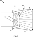
- FIG. 5 is a diagram of a cold-spray nozzle 500 that may be used in conjunction with a 3-D printer (e.g., 300, 400) employing spray forming such as the 3-D printer (e.g., 300, 400) employing spray forming illustrated with respect to FIGS. 3-4 .
- a 3-D printer e.g., 300, 400
- spray forming such as the 3-D printer (e.g., 300, 400) employing spray forming illustrated with respect to FIGS. 3-4 .
- the print resolution control may be mid-print, e.g., the resolution may be changed during the course of printing a particular item, e.g., using the 3-D printer (e.g., 300, 400).
- the print resolution control may be used for cold-spray additive manufacturing.
- the systems and methods described herein may include a cold-spray nozzle 500 with a variable diameter convergent part 502 and a variable diameter divergent part 504 forming a diffuser (e.g., variable diameter divergent part 504).
- one aspect may include a series of hinges 506 and overlapping sheets 508 to control the diameter (d 1 ) of the converging section (e.g., variable diameter convergent part 502) and the diameter (d 2 ) of the diverging sections (e.g., variable diameter divergent part 504) of a cold-spray gun (cold-spray nozzle 500).
- the resolution of metal deposited depends on a resulting particle flow.
- the resulting particle flow may depend strongly on the choke point 510 and outlet diameter (d 2 ).
- By varying both the choke point 510 and outlet diameter (d 2 ) it is possible to change, mid-print, the resulting area of deposition, e.g., by an order of magnitude.
- Previous cold-spray guns have machined converging-diverging nozzles and require switching the physical nozzle to change the deposition area.
- a cold-spray nozzle 500 includes a variable diameter convergent part 502. Additionally, the cold-spray nozzle 500 includes a variable diameter divergent part 504 forming a diffuser. The cold-spray nozzle 500 also includes a ring portion 510 coupling the variable diameter convergent part 502 and the variable diameter divergent part 504. The ring portion 510 controls the opening to the diffuser, e.g., the variable diameter divergent part 504.
- variable diameter convergent part 502 comprises a nozzle 500 containing a series of hinges 506 and overlapping sheets 508 within the nozzle 500, the hinges 506 and overlapping sheets 508 configured to control the diameter (d 1 ) of the variable diameter convergent part 502.
- variable diameter divergent part 504 comprises a nozzle containing a series of hinges 506 and overlapping sheets 508 within the nozzle, the hinges 506 and overlapping sheets 508 configured to control the diameter (d 2 ) of the variable diameter divergent part 504.
- the size of the ring portion 510 is variable.
- the size of the ring portion 510 controls a flow of a cold-spray.
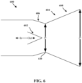
- FIG. 6 is another diagram of a cold-spray nozzle 600 that may be used in conjunction with a 3-D printer (e.g., 300, 400) employing spray forming such as the 3-D printer (e.g., 300, 400) employing spray forming illustrated with respect to FIGS. 3-4 .
- a 3-D printer e.g., 300, 400
- spray forming such as the 3-D printer (e.g., 300, 400) employing spray forming illustrated with respect to FIGS. 3-4 .
- the print resolution control may be mid-print, e.g., resolution may be changed during the course of printing a particular item, e.g., using the 3-D printer (e.g., 300, 400).
- the print resolution control may be used for cold-spray additive manufacturing.
- the systems and methods described herein may include a cold-spray nozzle 600 with a variable diameter divergent part that includes a plug nozzle.
- one aspect may include a plug nozzle 602 inside the cold-spray nozzle 600 to control the usable diameter where the converging section 606 and the divergent section 608 meet.
- the choke point 610 has a diameter, di.
- the portion of the choke point 610 that is actually available for a flow of cold-spray material out of the cold-spray nozzle 600 may be adjusted using the plug nozzle 602. For example, as the plug nozzle 602 moves in and out within the cold-spray nozzle 600, the , usable portion allowing material flow enlarges or decreases within a choke point 610.
- the outer diameter of the choke point 610 may remain a diameter, di.
- the usable portion of the choke point 610 having the diameter (d 1 ) increases.
- the usable portion of the choke point 610 having the diameter (d 1 ) decreases.
- the resolution of metal deposited depends on a resulting particle flow.
- the resulting particle flow may depend strongly on the portion of the choke point 610 available for material flow. While the diameter (d 1 ) and the outlet diameter (d 2 ) may be fixed, flow through the choke point may be adjusted by moving the plug nozzle 602. By varying the position of the plug nozzle 602, it may be possible to change, mid-print, the resulting area of deposition, e.g., by an order of magnitude.
- a cold-spray nozzle 600 includes a variable usable diameter convergent part 606.
- a cold-spray device (100, 300, 400) includes a material hopper (or spool 104).
- the cold-spray device (100, 300, 400) may also include a pressurized gas feed (not shown) coupled to the material hopper.
- the cold-spray device (100, 300, 400) may include a cold-spray nozzle (126, 128, 316, 416, 500, 600) coupled to the pressurized gas feed and configured to receive material from the material hopper.
- the cold-spray nozzle (126, 128, 316, 416, 500, 600) includes a variable diameter convergent part (502, 606), a variable diameter divergent part (504, 604) forming a diffuser, and a ring portion (510) coupling the variable diameter convergent part (502, 606) and the variable diameter divergent part (504, 604) and controlling the opening to the diffuser, e.g., variable diameter divergent part (504, 608).
- FIG. 7 is a flow diagram illustrating an exemplary method of cold-spray forming a part.
- cold-spray at least a first portion of a first layer of the part.
- cold-spray e.g., using a cold-spray nozzle 126, 128, 316, 416, 500, 600 on a cold-spray device 100, 300, 400
- first layer and the second layer may be different layers.
- the first layer and the second layer may be a same layer.
- the nozzle includes the variable diameter convergent part.
- a processing system on a cold-spray device (100, 300, 400) or connected to a cold-spray device (100, 300, 400) may determine if an adjustment of a variable diameter convergent part (502, 606) and a variable diameter divergent part (504) is needed.
- the nozzle (126, 128, 316, 416, 500, 600 ) includes the variable diameter convergent part (502, 606) is needed.
- the adjusting occurs continuously over the same layer.
- the adjusting may be without interruption or without gaps, e.g., over a particular interval when spray-forming is occurring.
- the adjusting occurs continually over the same layer.
- the adjusting may frequently be repeated in the same way, or regularly, e.g., over a particular interval when spray-forming is occurring.
- the method may proceed to block 730 (below).
- the method may continue cold-spraying, e.g., return to block 710, e.g., over a particular interval when spray-forming is occurring.
- the cold-spray may end (not shown), e.g., when a part is completed, a device implementing the method needs adj ustment, fixing, replenishment of materials, or some other change, alteration, modification, adjustment, variation, or adaptation.
- a variable diameter convergent part and a variable diameter divergent part in a nozzle are adjusted.
- the nozzle includes the variable diameter convergent part and the variable diameter divergent part.
- the variable diameter divergent part forms a diffuser.
- a ring portion couples the variable diameter convergent part and the variable diameter divergent part.
- a processing system on or connected to a cold-spray device 100, 300, 400 may control a nozzle (126, 128, 316, 416, 500, 600) such that the nozzle (126, 128, 316, 416, 500, 600) is adjusted.
- the nozzle (126, 128, 316, 416, 500, 600) includes a variable diameter convergent part (502, 606) and a variable diameter divergent part (504) in a nozzle (126, 128, 316, 416, 500, 600) including the variable diameter convergent part (502, 606).
- the variable diameter divergent part (504) forms a diffuser.
- a ring portion (510) couples the variable diameter convergent (502, 606) part and the variable diameter divergent part (504).
- a convergent part (606) may vary using a plug nozzle (602).
- At 740 at least a second portion of a second layer of the part is cold-sprayed using the adjusted variable diameter convergent part and the adjusted variable diameter divergent part.
- a cold-spray device 100, 300, 400 may cold-spray at least a second portion of a second layer of the part using the adjusted variable diameter convergent part (502, 606) and the adjusted variable diameter divergent part (504).
- the method may repeat with subsequent first layers and the first portion or a subsequent "first" portion. In other words, a subsequent execution of block 710 may follow block 714. Alternatively, the method may end after execution of block 740 (not shown).
Landscapes
- Engineering & Computer Science (AREA)
- Chemical & Material Sciences (AREA)
- Materials Engineering (AREA)
- Manufacturing & Machinery (AREA)
- Mechanical Engineering (AREA)
- Chemical Kinetics & Catalysis (AREA)
- Metallurgy (AREA)
- Organic Chemistry (AREA)
- Physics & Mathematics (AREA)
- Plasma & Fusion (AREA)
- Powder Metallurgy (AREA)
Claims (11)
- Dispositif de pulvérisation à froid (100, 300, 400) comprenant :une trémie de matériau (104) ; etun bras robotique (314) configuré pour être manipulé dans une pluralité de directions et d'angles et comprenant une buse (126, 128, 316, 416, 500, 600), dans lequel la buse est configurée pour recevoir un matériau en provenance de la trémie de matériau pour former au moins une première portion sur une première couche d'une pièce (121, 310, 408) et comprenant :une partie convergente de diamètre variable (502, 606) ;une partie divergente de diamètre variable (504, 604) comprenant un diffuseur ; etune portion annulaire (510) couplant la partie convergente de diamètre variable et la partie divergente de diamètre variable, dans lequel la portion annulaire présente une taille variable et est configurée pour commander une ouverture du diffuseur.
- Dispositif de pulvérisation à froid selon la revendication 1, dans lequel la partie convergente de diamètre variable comprend une section convergente (606).
- Dispositif de pulvérisation à froid selon la revendication 2, dans lequel la section convergente inclut une série de charnières (506) et de feuilles chevauchantes (508), les charnières et les feuilles chevauchantes étant configurées pour commander un diamètre de la section convergente.
- Dispositif de pulvérisation à froid selon la revendication 1, dans lequel la partie convergente de diamètre variable comprend une tuyère à noyau central (602).
- Dispositif de pulvérisation à froid selon la revendication 4, dans lequel une portion d'un point d'étranglement (510, 610) disponible pour permettre un écoulement du matériau hors de la buse est ajustée en utilisant la tuyère à noyau central.
- Dispositif de pulvérisation à froid selon la revendication 1, comprenant en outre :une alimentation en gaz sous pression couplée à la trémie de matériau ; etla buse est couplée à l'alimentation en gaz sous pression.
- Dispositif de pulvérisation à froid 6, comprenant en outre une plate-forme de construction mobile (110).
- Procédé de formation par pulvérisation à froid d'une pièce (121, 310, 408) comprenant :la fourniture d'une pulvérisation à froid à une buse (126, 128, 316, 416, 500, 600) d'un bras robotique (314), dans lequel la buse pulvérise à froid au moins une première portion d'une première couche de la pièce, dans lequel la buse comprend une partie convergente de diamètre variable (502, 606), une partie divergente de diamètre variable (504, 604) comprenant un diffuseur, et une portion annulaire (510) couplant la partie convergente de diamètre variable et la partie divergente de diamètre variable, dans lequel la portion annulaire présente une taille variable ;l'ajustement de la partie convergente de diamètre variable et de la partie divergente de diamètre variable dans la buse ; etla pulvérisation à froid d'au moins une seconde portion d'une seconde couche de la pièce en utilisant la partie convergente de diamètre variable ajustée et la partie divergente de diamètre variable ajustée.
- Procédé selon la revendication 8, dans lequel la première couche et la seconde couche comprennent différentes couches.
- Procédé selon la revendication 8, dans lequel la première couche et la seconde couche comprennent une même couche.
- Procédé selon la revendication 10, dans lequel l'ajustement a lieu en continu sans interruption ou sans décalages sur un intervalle particulier lorsque la formation par pulvérisation à froid s'effectue ou en continu sur la même couche.
Applications Claiming Priority (2)
| Application Number | Priority Date | Filing Date | Title |
|---|---|---|---|
| US16/029,418 US11292056B2 (en) | 2018-07-06 | 2018-07-06 | Cold-spray nozzle |
| PCT/US2019/040344 WO2020010109A1 (fr) | 2018-07-06 | 2019-07-02 | Buse de pulvérisation à froid |
Publications (3)
| Publication Number | Publication Date |
|---|---|
| EP3817829A1 EP3817829A1 (fr) | 2021-05-12 |
| EP3817829A4 EP3817829A4 (fr) | 2022-01-05 |
| EP3817829B1 true EP3817829B1 (fr) | 2024-04-17 |
Family
ID=69059306
Family Applications (1)
| Application Number | Title | Priority Date | Filing Date |
|---|---|---|---|
| EP19830834.8A Active EP3817829B1 (fr) | 2018-07-06 | 2019-07-02 | Dispositif de projection à froid et procédé de formation d'une pièce par projection à froid |
Country Status (4)
| Country | Link |
|---|---|
| US (1) | US11292056B2 (fr) |
| EP (1) | EP3817829B1 (fr) |
| CN (1) | CN113038995B (fr) |
| WO (1) | WO2020010109A1 (fr) |
Families Citing this family (4)
| Publication number | Priority date | Publication date | Assignee | Title |
|---|---|---|---|---|
| US9335296B2 (en) | 2012-10-10 | 2016-05-10 | Westinghouse Electric Company Llc | Systems and methods for steam generator tube analysis for detection of tube degradation |
| US11935662B2 (en) | 2019-07-02 | 2024-03-19 | Westinghouse Electric Company Llc | Elongate SiC fuel elements |
| KR102523509B1 (ko) | 2019-09-19 | 2023-04-18 | 웨스팅하우스 일렉트릭 컴퍼니 엘엘씨 | 콜드 스프레이 침착물의 현장 접착 테스트를 수행하기 위한 장치 및 사용 방법 |
| JP2024099073A (ja) * | 2021-03-22 | 2024-07-25 | パナソニックIpマネジメント株式会社 | コールドスプレーノズル、コールドスプレー装置、および、コールドスプレー方法 |
Family Cites Families (307)
| Publication number | Priority date | Publication date | Assignee | Title |
|---|---|---|---|---|
| US2982089A (en) | 1955-06-24 | 1961-05-02 | Gen Motors Corp | Afterburner nozzle |
| US3146669A (en) * | 1962-10-24 | 1964-09-01 | Calvin J Wolf | Collapsible nozzle exit cone for tube launched missile |
| US5203226A (en) | 1990-04-17 | 1993-04-20 | Toyoda Gosei Co., Ltd. | Steering wheel provided with luminous display device |
| DE29507827U1 (de) | 1995-05-16 | 1995-07-20 | Edag Engineering + Design Ag, 36039 Fulda | Zum Zuführen von Schweißbolzen zu einer Schweißpistole bestimmte Zuführvorrichtung |
| DE19518175A1 (de) | 1995-05-19 | 1996-11-21 | Edag Eng & Design Ag | Verfahren zum automatischen Einbau eines Bauteils einer Kraftfahrzeugkarosserie |
| DE19519643B4 (de) | 1995-05-30 | 2005-09-22 | Edag Engineering + Design Ag | Behälter-Wechselvorrichtung |
| US6252196B1 (en) | 1996-10-11 | 2001-06-26 | Technolines Llc | Laser method of scribing graphics |
| US5990444A (en) | 1995-10-30 | 1999-11-23 | Costin; Darryl J. | Laser method and system of scribing graphics |
| US6046426A (en) | 1996-07-08 | 2000-04-04 | Sandia Corporation | Method and system for producing complex-shape objects |
| US5742385A (en) | 1996-07-16 | 1998-04-21 | The Boeing Company | Method of airplane interiors assembly using automated rotating laser technology |
| WO1998024958A1 (fr) | 1996-12-05 | 1998-06-11 | Teijin Limited | Procede de moulage d'agregats de fibres |
| US6010155A (en) | 1996-12-31 | 2000-01-04 | Dana Corporation | Vehicle frame assembly and method for manufacturing same |
| US6140602A (en) | 1997-04-29 | 2000-10-31 | Technolines Llc | Marking of fabrics and other materials using a laser |
| US5975493A (en) | 1997-09-10 | 1999-11-02 | The University Of Chicago | Process for controlling flow rate of viscous materials including use of a nozzle with changeable opening |
| SE509041C2 (sv) | 1997-10-23 | 1998-11-30 | Ssab Hardtech Ab | Krockskyddsbalk för fordon |
| DE19907015A1 (de) | 1999-02-18 | 2000-08-24 | Edag Eng & Design Ag | In Fertigungslinien für Kraftfahrzeuge einsetzbare Spannvorrichtung und Fertigungslinie mit einer solchen Spannvorrichtung |
| US6391251B1 (en) | 1999-07-07 | 2002-05-21 | Optomec Design Company | Forming structures from CAD solid models |
| US6811744B2 (en) | 1999-07-07 | 2004-11-02 | Optomec Design Company | Forming structures from CAD solid models |
| US6409930B1 (en) | 1999-11-01 | 2002-06-25 | Bmc Industries, Inc. | Lamination of circuit sub-elements while assuring registration |
| US6468439B1 (en) | 1999-11-01 | 2002-10-22 | Bmc Industries, Inc. | Etching of metallic composite articles |
| US6365057B1 (en) | 1999-11-01 | 2002-04-02 | Bmc Industries, Inc. | Circuit manufacturing using etched tri-metal media |
| US6318642B1 (en) | 1999-12-22 | 2001-11-20 | Visteon Global Tech., Inc | Nozzle assembly |
| FR2805008B1 (fr) | 2000-02-16 | 2002-05-31 | Joseph Haiun | Compresseur termocinetique |
| JP2001271710A (ja) | 2000-03-24 | 2001-10-05 | Ishikawajima Harima Heavy Ind Co Ltd | ジェットエンジン用騒音低減装置及び排気ノズル |
| US6585151B1 (en) | 2000-05-23 | 2003-07-01 | The Regents Of The University Of Michigan | Method for producing microporous objects with fiber, wire or foil core and microporous cellular objects |
| US6919035B1 (en) | 2001-05-18 | 2005-07-19 | Ensci Inc. | Metal oxide coated polymer substrates |
| JP3889940B2 (ja) | 2001-06-13 | 2007-03-07 | 株式会社東海理化電機製作所 | 金型装置、金型装置の使用方法、及び金型装置の共用方法 |
| ES2263848T3 (es) | 2001-08-31 | 2006-12-16 | Edag Engineering + Design Aktiengesellschaft | Cabezal plegador de rodillo y procedimiento para plegar un reborde. |
| CN100406190C (zh) | 2001-11-02 | 2008-07-30 | 波音公司 | 形成具有残余压应力分布形式的焊接接头的装置和方法 |
| US6644721B1 (en) | 2002-08-30 | 2003-11-11 | Ford Global Technologies, Llc | Vehicle bed assembly |
| DE10325906B4 (de) | 2003-06-05 | 2007-03-15 | Erwin Martin Heberer | Vorrichtung zur Abschirmung von kohärenter elektromagnetischer Strahlung sowie Laserkabine mit einer solchen Vorrichtung |
| DE102004014662A1 (de) | 2004-03-25 | 2005-10-13 | Audi Ag | Anordnung mit einer Fahrzeug-Sicherung und einem Analog/Digital-Wandler |
| US7745293B2 (en) | 2004-06-14 | 2010-06-29 | Semiconductor Energy Laboratory Co., Ltd | Method for manufacturing a thin film transistor including forming impurity regions by diagonal doping |
| DE502005001712D1 (de) | 2004-09-24 | 2007-11-29 | Edag Eng & Design Ag | Bördelvorrichtung und Bördelverfahren mit Bauteilschutz |
| US20060108783A1 (en) | 2004-11-24 | 2006-05-25 | Chi-Mou Ni | Structural assembly for vehicles and method of making same |
| DE102005004474B3 (de) | 2005-01-31 | 2006-08-31 | Edag Engineering + Design Ag | Bördelvorrichtung und Bördelverfahren zum Umlegen eines Bördelstegs eines Bauteils um eine Bördelkante |
| DE102005030944B4 (de) | 2005-06-30 | 2007-08-02 | Edag Engineering + Design Ag | Verfahren und Vorrichtung zum Fügen von Fügestrukturen, insbesondere in der Montage von Fahrzeugbauteilen |
| EP1928963B1 (fr) | 2005-09-28 | 2012-03-21 | Dip Tech. Ltd. | Encre a effet de gravure pour impression sur des surfaces en ceramique |
| US7716802B2 (en) | 2006-01-03 | 2010-05-18 | The Boeing Company | Method for machining using sacrificial supports |
| DE102006014282A1 (de) | 2006-03-28 | 2007-10-04 | Edag Engineering + Design Ag | Spannvorrichtung zum Aufnehmen und Spannen von Bauteilen |
| DE102006014279A1 (de) | 2006-03-28 | 2007-10-04 | Edag Engineering + Design Ag | Spannvorrichtung zum Aufnehmen und Spannen von Bauteilen |
| JP2007292048A (ja) | 2006-03-29 | 2007-11-08 | Yamaha Motor Co Ltd | 鞍乗型車両用排気装置および鞍乗型車両 |
| JP5934459B2 (ja) | 2006-04-17 | 2016-06-15 | オムニビジョン テクノロジーズ, インコーポレイテッド | アレイ化撮像システムおよび関連方法 |
| DE102006021755A1 (de) | 2006-05-10 | 2007-11-15 | Edag Engineering + Design Ag | Energiestrahl-Löten oder -Schweißen von Bauteilen |
| JP2007317750A (ja) | 2006-05-23 | 2007-12-06 | Matsushita Electric Ind Co Ltd | 撮像装置 |
| DE102006038795A1 (de) | 2006-08-18 | 2008-03-20 | Fft Edag Produktionssysteme Gmbh & Co. Kg | Überwachungsvorrichtung für eine Laserbearbeitungsvorrichtung |
| DE602006014830D1 (de) | 2006-09-14 | 2010-07-22 | Ibiden Co Ltd | Verfahren zur Herstellung eines Wabenkörpers und Zusammensetzung für Sinterwabenkörper |
| DE202006018552U1 (de) | 2006-12-08 | 2007-02-22 | Edag Engineering + Design Ag | Bördelhandgerät |
| US7344186B1 (en) | 2007-01-08 | 2008-03-18 | Ford Global Technologies, Llc | A-pillar structure for an automotive vehicle |
| DE102007002856B4 (de) | 2007-01-15 | 2012-02-09 | Edag Gmbh & Co. Kgaa | Vorrichtung zum Bördeln und Schweißen oder Löten von Bauteilen |
| EP1949981B1 (fr) | 2007-01-18 | 2015-04-29 | Toyota Motor Corporation | Assemblage de pièces en tôle |
| DE202007003110U1 (de) | 2007-03-02 | 2007-08-02 | Edag Engineering + Design Ag | Automobil mit erleichtertem Fahrgastausstieg |
| US7710347B2 (en) | 2007-03-13 | 2010-05-04 | Raytheon Company | Methods and apparatus for high performance structures |
| DE102007022102B4 (de) | 2007-05-11 | 2014-04-10 | Fft Edag Produktionssysteme Gmbh & Co. Kg | Bördeln von Bauteilen in Serienfertigungen mit kurzen Taktzeiten |
| DE202007007838U1 (de) | 2007-06-01 | 2007-09-13 | Edag Engineering + Design Ag | Rollbördelwerkzeug |
| ES2760927T3 (es) | 2007-07-13 | 2020-05-18 | Advanced Ceramics Mfg Llc | Mandriles basados en áridos para la producción de piezas de material compuesto y métodos de producción de piezas de material compuesto |
| WO2009014233A1 (fr) | 2007-07-20 | 2009-01-29 | Nippon Steel Corporation | Procédé d'hydroformage et pièces hydroformées |
| US9626487B2 (en) | 2007-12-21 | 2017-04-18 | Invention Science Fund I, Llc | Security-activated production device |
| US9818071B2 (en) | 2007-12-21 | 2017-11-14 | Invention Science Fund I, Llc | Authorization rights for operational components |
| US8429754B2 (en) | 2007-12-21 | 2013-04-23 | The Invention Science Fund I, Llc | Control technique for object production rights |
| US9128476B2 (en) | 2007-12-21 | 2015-09-08 | The Invention Science Fund I, Llc | Secure robotic operational system |
| US8752166B2 (en) | 2007-12-21 | 2014-06-10 | The Invention Science Fund I, Llc | Security-activated operational components |
| US9071436B2 (en) | 2007-12-21 | 2015-06-30 | The Invention Science Fund I, Llc | Security-activated robotic system |
| US8286236B2 (en) | 2007-12-21 | 2012-10-09 | The Invention Science Fund I, Llc | Manufacturing control system |
| DE102008003067B4 (de) | 2008-01-03 | 2013-05-29 | Edag Gmbh & Co. Kgaa | Verfahren und Biegewerkzeug zum Biegen eines Werkstücks |
| US7908922B2 (en) | 2008-01-24 | 2011-03-22 | Delphi Technologies, Inc. | Silicon integrated angular rate sensor |
| DE102008008306A1 (de) | 2008-02-07 | 2009-08-13 | Edag Gmbh & Co. Kgaa | Drehtisch |
| DE102008013591B4 (de) | 2008-03-11 | 2010-02-18 | Edag Gmbh & Co. Kgaa | Werkzeug, Anlage und Verfahren zur Herstellung eines Kabelbaums |
| DE102008047800B4 (de) | 2008-05-09 | 2021-11-18 | Fft Produktionssysteme Gmbh & Co. Kg | Verfahren und Werkzeug zur Herstellung einer Fixierverbindung an formschlüssig gefügten Bauteilen |
| EP2824526B1 (fr) | 2008-05-21 | 2020-08-19 | FFT Produktionssysteme GmbH & Co. KG | Jointoiement de composants sans cadre de serrage |
| WO2009154484A2 (fr) | 2008-06-20 | 2009-12-23 | Business Intelligence Solutions Safe B.V. | Procédés, dispositifs et systèmes de visualisation de données et applications connexes |
| US8383028B2 (en) | 2008-11-13 | 2013-02-26 | The Boeing Company | Method of manufacturing co-molded inserts |
| US8452073B2 (en) | 2009-04-08 | 2013-05-28 | The United States Of America As Represented By The Administrator Of The National Aeronautics And Space Administration | Closed-loop process control for electron beam freeform fabrication and deposition processes |
| DE102009018618B4 (de) | 2009-04-27 | 2018-09-06 | Fft Produktionssysteme Gmbh & Co. Kg | Spannvorrichtung, Anlage und Verfahren zur Bearbeitung wechselnder Bauteiltypen |
| DE102009018619B4 (de) | 2009-04-27 | 2014-07-17 | Fft Edag Produktionssysteme Gmbh & Co. Kg | Roboterabstützung |
| DE102009024344B4 (de) | 2009-06-09 | 2011-02-24 | Edag Gmbh & Co. Kgaa | Verfahren und Werkzeug zum Bördeln eines Werkstücks |
| DE202009012432U1 (de) | 2009-09-15 | 2010-01-28 | Edag Gmbh & Co. Kgaa | Karosseriebauteil |
| US8354170B1 (en) | 2009-10-06 | 2013-01-15 | Hrl Laboratories, Llc | Elastomeric matrix composites |
| US8610761B2 (en) | 2009-11-09 | 2013-12-17 | Prohectionworks, Inc. | Systems and methods for optically projecting three-dimensional text, images and/or symbols onto three-dimensional objects |
| US8606540B2 (en) | 2009-11-10 | 2013-12-10 | Projectionworks, Inc. | Hole measurement apparatuses |
| US8755923B2 (en) | 2009-12-07 | 2014-06-17 | Engineering Technology Associates, Inc. | Optimization system |
| US8686997B2 (en) | 2009-12-18 | 2014-04-01 | Sassault Systemes | Method and system for composing an assembly |
| DE102010047969A1 (de) | 2010-03-31 | 2011-10-06 | Sms Siemag Aktiengesellschaft | Vorrichtung zur Einblasung von Gas in ein metallurgisches Gefäß |
| EP2383669B1 (fr) | 2010-04-02 | 2018-07-11 | Dassault Systèmes | Conception d'une pièce modelée par des courbes géodésiques parallèles |
| EP2583253A2 (fr) | 2010-06-21 | 2013-04-24 | Johan Gielis | Systèmes et procédés de boîte à outils mis en uvre par ordinateur |
| US8289352B2 (en) | 2010-07-15 | 2012-10-16 | HJ Laboratories, LLC | Providing erasable printing with nanoparticles |
| US8978535B2 (en) | 2010-08-11 | 2015-03-17 | Massachusetts Institute Of Technology | Articulating protective system for resisting mechanical loads |
| EP2799150B1 (fr) | 2013-05-02 | 2016-04-27 | Hexagon Technology Center GmbH | Système d'application graphique |
| US9858604B2 (en) | 2010-09-24 | 2018-01-02 | Amazon Technologies, Inc. | Vendor interface for item delivery via 3D manufacturing on demand |
| US9898776B2 (en) | 2010-09-24 | 2018-02-20 | Amazon Technologies, Inc. | Providing services related to item delivery via 3D manufacturing on demand |
| US9672550B2 (en) | 2010-09-24 | 2017-06-06 | Amazon Technologies, Inc. | Fulfillment of orders for items using 3D manufacturing on demand |
| US9684919B2 (en) | 2010-09-24 | 2017-06-20 | Amazon Technologies, Inc. | Item delivery using 3D manufacturing on demand |
| US9566758B2 (en) | 2010-10-19 | 2017-02-14 | Massachusetts Institute Of Technology | Digital flexural materials |
| US9023121B2 (en) | 2010-10-20 | 2015-05-05 | Alliant Techsystems Inc. | Solid feed systems for elevated pressure processes, gasification systems and related methods |
| US9294011B2 (en) | 2011-02-07 | 2016-03-22 | Ion Geophysical Corporation | Method and apparatus for sensing underwater signals |
| EP2495292B1 (fr) | 2011-03-04 | 2013-07-24 | FFT EDAG Produktionssysteme GmbH & Co. KG | Dispositif de prétraitement de surfaces d'assemblage et procédé de prétraitement de surfaces d'assemblage |
| CN103717378B (zh) | 2011-06-02 | 2016-04-27 | A·雷蒙德公司 | 通过三维印刷制造的紧固件 |
| US9246299B2 (en) | 2011-08-04 | 2016-01-26 | Martin A. Stuart | Slab laser and amplifier |
| US9101979B2 (en) | 2011-10-31 | 2015-08-11 | California Institute Of Technology | Methods for fabricating gradient alloy articles with multi-functional properties |
| US10011089B2 (en) | 2011-12-31 | 2018-07-03 | The Boeing Company | Method of reinforcement for additive manufacturing |
| DE102012101939A1 (de) | 2012-03-08 | 2013-09-12 | Klaus Schwärzler | Verfahren und Vorrichtung zum schichtweisen Aufbau eines Formkörpers |
| US9566742B2 (en) | 2012-04-03 | 2017-02-14 | Massachusetts Institute Of Technology | Methods and apparatus for computer-assisted spray foam fabrication |
| US9469057B2 (en) | 2012-05-18 | 2016-10-18 | 3D Systems, Inc. | Support structures and deposition techniques for 3D printing |
| US8873238B2 (en) | 2012-06-11 | 2014-10-28 | The Boeing Company | Chassis system and method for holding and protecting electronic modules |
| US9533526B1 (en) | 2012-06-15 | 2017-01-03 | Joel Nevins | Game object advances for the 3D printing entertainment industry |
| WO2013192599A1 (fr) | 2012-06-21 | 2013-12-27 | Massachusetts Institute Of Technology | Procédés et appareil pour peaux de matière digitale |
| US9672389B1 (en) | 2012-06-26 | 2017-06-06 | The Mathworks, Inc. | Generic human machine interface for a graphical model |
| EP2689865B1 (fr) | 2012-07-27 | 2016-09-14 | FFT Produktionssysteme GmbH & Co. KG | Presse à border |
| WO2014019998A1 (fr) | 2012-07-30 | 2014-02-06 | Materialise Nv | Systèmes et procédés de formation et d'utilisation de cartes pliantes pour la création d'un objet |
| US8437513B1 (en) | 2012-08-10 | 2013-05-07 | EyeVerify LLC | Spoof detection for biometric authentication |
| US10029415B2 (en) | 2012-08-16 | 2018-07-24 | Stratasys, Inc. | Print head nozzle for use with additive manufacturing system |
| US9389315B2 (en) | 2012-12-19 | 2016-07-12 | Basf Se | Detector comprising a transversal optical sensor for detecting a transversal position of a light beam from an object and a longitudinal optical sensor sensing a beam cross-section of the light beam in a sensor region |
| US9329020B1 (en) | 2013-01-02 | 2016-05-03 | Lockheed Martin Corporation | System, method, and computer program product to provide wireless sensing based on an aggregate magnetic field reading |
| US9244986B2 (en) | 2013-01-11 | 2016-01-26 | Buckyball Mobile, Inc. | Method and system for interactive geometric representations, configuration and control of data |
| US9609755B2 (en) | 2013-01-17 | 2017-03-28 | Hewlett-Packard Development Company, L.P. | Nanosized particles deposited on shaped surface geometries |
| US9626489B2 (en) | 2013-03-13 | 2017-04-18 | Intertrust Technologies Corporation | Object rendering systems and methods |
| US20140277669A1 (en) | 2013-03-15 | 2014-09-18 | Sikorsky Aircraft Corporation | Additive topology optimized manufacturing for multi-functional components |
| US9764415B2 (en) | 2013-03-15 | 2017-09-19 | The United States Of America As Represented By The Administrator Of Nasa | Height control and deposition measurement for the electron beam free form fabrication (EBF3) process |
| US9555580B1 (en) | 2013-03-21 | 2017-01-31 | Temper Ip, Llc. | Friction stir welding fastener |
| US9126365B1 (en) | 2013-03-22 | 2015-09-08 | Markforged, Inc. | Methods for composite filament fabrication in three dimensional printing |
| US9149988B2 (en) | 2013-03-22 | 2015-10-06 | Markforged, Inc. | Three dimensional printing |
| CA3121870A1 (fr) | 2013-03-22 | 2014-09-25 | Markforged, Inc. | Impression tridimensionnelle |
| US9156205B2 (en) | 2013-03-22 | 2015-10-13 | Markforged, Inc. | Three dimensional printer with composite filament fabrication |
| US9186848B2 (en) | 2013-03-22 | 2015-11-17 | Markforged, Inc. | Three dimensional printing of composite reinforced structures |
| WO2014169238A1 (fr) | 2013-04-11 | 2014-10-16 | Digimarc Corporation | Procédés de reconnaissance d'objet et agencements associés |
| BR112015026696A2 (pt) | 2013-04-26 | 2017-07-25 | Dsm Ip Assets Bv | resinas de uretano de vinil funcionalizado para composições de revestimento em pó |
| ES2556564T3 (es) | 2013-05-22 | 2016-01-18 | Fft Produktionssysteme Gmbh & Co. Kg | Ensamblaje de una pieza de trabajo con una soldadura de ensamblaje escondida |
| EP2810749B1 (fr) | 2013-06-07 | 2015-04-29 | FFT Produktionssysteme GmbH & Co. KG | Dispositif pour l'utilisation lors de la manipulation d'une charge et procédé de fabrication d'un tel dispositif |
| EP2813432B1 (fr) | 2013-06-13 | 2017-12-20 | Airbus Operations GmbH | Procédé d'installation d'un élément de fixation |
| AU2014280332B2 (en) | 2013-06-13 | 2017-09-07 | Basf Se | Detector for optically detecting at least one object |
| CN105210190A (zh) | 2013-06-13 | 2015-12-30 | 巴斯夫欧洲公司 | 光学检测器及其制造方法 |
| US9724877B2 (en) | 2013-06-23 | 2017-08-08 | Robert A. Flitsch | Methods and apparatus for mobile additive manufacturing of advanced structures and roadways |
| US9688032B2 (en) | 2013-07-01 | 2017-06-27 | GM Global Technology Operations LLC | Thermoplastic component repair |
| GB201313841D0 (en) | 2013-08-02 | 2013-09-18 | Rolls Royce Plc | Method of Manufacturing a Component |
| GB201313839D0 (en) | 2013-08-02 | 2013-09-18 | Rolls Royce Plc | Method of Manufacturing a Component |
| GB201313840D0 (en) | 2013-08-02 | 2013-09-18 | Rolls Royce Plc | Method of Manufacturing a Component |
| AU2014310703B2 (en) | 2013-08-19 | 2018-09-27 | Basf Se | Optical detector |
| JP6483127B2 (ja) | 2013-08-19 | 2019-03-13 | ビーエーエスエフ ソシエタス・ヨーロピアBasf Se | 少なくとも1つの対象物の位置を求めるための検出器 |
| US10197338B2 (en) | 2013-08-22 | 2019-02-05 | Kevin Hans Melsheimer | Building system for cascading flows of matter and energy |
| US10052820B2 (en) | 2013-09-13 | 2018-08-21 | Made In Space, Inc. | Additive manufacturing of extended structures |
| WO2015053940A1 (fr) | 2013-10-07 | 2015-04-16 | United Technologies Corporation | Meilleures caractéristiques de résistance au choc développées de manière additive pour une structure perfectionnée et une meilleure protection de jonction |
| US9248611B2 (en) | 2013-10-07 | 2016-02-02 | David A. Divine | 3-D printed packaging |
| US10086568B2 (en) | 2013-10-21 | 2018-10-02 | Made In Space, Inc. | Seamless scanning and production devices and methods |
| US10705509B2 (en) | 2013-10-21 | 2020-07-07 | Made In Space, Inc. | Digital catalog for manufacturing |
| EP3071651B1 (fr) | 2013-11-21 | 2017-12-20 | DSM IP Assets B.V. | Compositions de revêtement en poudre thermodurcissable renfermant du peroxyde de benzoyle à substitution méthyle |
| KR20160086826A (ko) | 2013-11-21 | 2016-07-20 | 사빅 글로벌 테크놀러지스 비.브이. | 감소된 밀도 물품 |
| EP3074951B1 (fr) | 2013-11-25 | 2022-01-05 | 7D Surgical ULC | Système et procédé de génération de surface partielle à partir de données volumétriques pour alignement sur des données d'image de topologie de surface |
| US9555315B2 (en) | 2013-12-05 | 2017-01-31 | Aaron Benjamin Aders | Technologies for transportation |
| US9604124B2 (en) | 2013-12-05 | 2017-03-28 | Aaron Benjamin Aders | Technologies for transportation |
| EP2886448B1 (fr) | 2013-12-20 | 2017-03-08 | Airbus Operations GmbH | Élément porteur de charge et procédé de fabrication dudit élément |
| TW201527070A (zh) | 2014-01-06 | 2015-07-16 | Prior Company Ltd | 裝飾薄膜及其製造方法以及加飾成型品的製造方法 |
| WO2015105024A1 (fr) | 2014-01-10 | 2015-07-16 | 勝義 近藤 | Matériau en poudre de titane, matériau de titane et procédé d'obtention de matériau en poudre de titane sous forme de solution solide avec de l'oxygène |
| US9932841B2 (en) | 2014-01-17 | 2018-04-03 | United Technologies Corporation | Workpiece manufactured from an additive manufacturing system having a particle separator and method of operation |
| JP6261618B2 (ja) | 2014-01-24 | 2018-01-17 | 勝義 近藤 | チタン素材および窒素固溶チタン粉末材料の製造方法 |
| US9424503B2 (en) | 2014-08-11 | 2016-08-23 | Brian Kieser | Structurally encoded component and method of manufacturing structurally encoded component |
| SG10201807147TA (en) | 2014-02-24 | 2018-09-27 | Univ Singapore Technology & Design | Verification methods and verification devices |
| US9817922B2 (en) | 2014-03-01 | 2017-11-14 | Anguleris Technologies, Llc | Method and system for creating 3D models from 2D data for building information modeling (BIM) |
| US9782936B2 (en) | 2014-03-01 | 2017-10-10 | Anguleris Technologies, Llc | Method and system for creating composite 3D models for building information modeling (BIM) |
| US9703896B2 (en) | 2014-03-11 | 2017-07-11 | Microsoft Technology Licensing, Llc | Generation of custom modular objects |
| US10006156B2 (en) | 2014-03-21 | 2018-06-26 | Goodrich Corporation | Systems and methods for calculated tow fiber angle |
| US9765226B2 (en) | 2014-03-27 | 2017-09-19 | Disney Enterprises, Inc. | Ultraviolet printing with luminosity control |
| US10294982B2 (en) | 2014-03-28 | 2019-05-21 | The Boeing Company | Systems, methods, and apparatus for supported shafts |
| US10018576B2 (en) | 2014-04-09 | 2018-07-10 | Texas Instruments Incorporated | Material detection and analysis using a dielectric waveguide |
| KR101588762B1 (ko) | 2014-04-09 | 2016-01-26 | 현대자동차 주식회사 | 차체 전방 구조물 |
| US9597843B2 (en) | 2014-05-15 | 2017-03-21 | The Boeing Company | Method and apparatus for layup tooling |
| ES2770053T3 (es) | 2014-05-16 | 2020-06-30 | Divergent Tech Inc | Nodos formados modulares para chasis de vehículo y sus métodos de uso |
| US9643361B2 (en) | 2014-05-27 | 2017-05-09 | Jian Liu | Method and apparatus for three-dimensional additive manufacturing with a high energy high power ultrafast laser |
| US10074128B2 (en) | 2014-06-08 | 2018-09-11 | Shay C. Colson | Pre-purchase mechanism for autonomous vehicles |
| DE202014102800U1 (de) | 2014-06-17 | 2014-06-27 | Fft Produktionssysteme Gmbh & Co. Kg | Segmentierte Bauteilauflage |
| CN106488819B (zh) | 2014-06-20 | 2018-06-22 | 维洛3D公司 | 用于三维打印的设备、系统和方法 |
| CN106573586B (zh) | 2014-07-25 | 2020-07-10 | 沙特基础工业全球技术有限公司 | 可压碎聚合物纵梁延伸件、系统及其制作和使用方法 |
| JP6740211B2 (ja) | 2014-08-04 | 2020-08-12 | ワシントン ステイト ユニバーシティー | 複合圧力容器における極低温貯蔵用の蒸気冷却遮蔽ライナ |
| US9783324B2 (en) | 2014-08-26 | 2017-10-10 | The Boeing Company | Vessel insulation assembly |
| WO2016038692A1 (fr) | 2014-09-09 | 2016-03-17 | グラフェンプラットフォーム株式会社 | Matériau carboné à base de graphite qui est utilisé comme précurseur de graphène, dispersion de graphène et composite de graphène le contenant, et son procédé de production |
| US9696238B2 (en) | 2014-09-16 | 2017-07-04 | The Boeing Company | Systems and methods for icing flight tests |
| CA2961026C (fr) | 2014-09-24 | 2022-11-08 | Holland Lp | Appareil de raccordement et d'espacement de grillages de fil, systeme, et procedes d'utilisation associes |
| US10285219B2 (en) | 2014-09-25 | 2019-05-07 | Aurora Flight Sciences Corporation | Electrical curing of composite structures |
| US9854828B2 (en) | 2014-09-29 | 2018-01-02 | William Langeland | Method, system and apparatus for creating 3D-printed edible objects |
| US10081140B2 (en) | 2014-10-29 | 2018-09-25 | The Boeing Company | Apparatus for and method of compaction of a prepreg |
| US10108766B2 (en) | 2014-11-05 | 2018-10-23 | The Boeing Company | Methods and apparatus for analyzing fatigue of a structure and optimizing a characteristic of the structure based on the fatigue analysis |
| EP3018051A1 (fr) | 2014-11-06 | 2016-05-11 | Airbus Operations GmbH | Composant structurel et procédé de fabrication associé |
| US10022792B2 (en) | 2014-11-13 | 2018-07-17 | The Indian Institute of Technology | Process of dough forming of polymer-metal blend suitable for shape forming |
| US10016852B2 (en) | 2014-11-13 | 2018-07-10 | The Boeing Company | Apparatuses and methods for additive manufacturing |
| WO2016077669A1 (fr) | 2014-11-13 | 2016-05-19 | Sabic Global Technologies B.V. | Composants aérodynamiques de véhicule réduisant la traînée et leurs procédés de fabrication |
| US9915527B2 (en) | 2014-11-17 | 2018-03-13 | The Boeing Company | Detachable protective coverings and protection methods |
| DE102014116938A1 (de) | 2014-11-19 | 2016-05-19 | Airbus Operations Gmbh | Herstellung von Komponenten eines Fahrzeugs unter Anwendung von Additive Layer Manufacturing |
| US9600929B1 (en) | 2014-12-01 | 2017-03-21 | Ngrain (Canada) Corporation | System, computer-readable medium and method for 3D-differencing of 3D voxel models |
| US9595795B2 (en) | 2014-12-09 | 2017-03-14 | Te Connectivity Corporation | Header assembly |
| DE102014225488A1 (de) | 2014-12-10 | 2016-06-16 | Fraunhofer-Gesellschaft zur Förderung der angewandten Forschung e.V. | Polymerzusammensetzung mit verzögertem Kristallisationsverhalten, das Kristallisationsverhalten beeinflussende Additivzusammensetzung, Verfahren zur Herabsetzung des Kristallisationspunktes sowie Verwendung einer Additivzusammensetzung |
| US10160278B2 (en) | 2014-12-16 | 2018-12-25 | Aktv8 LLC | System and method for vehicle stabilization |
| US9789922B2 (en) | 2014-12-18 | 2017-10-17 | The Braun Corporation | Modified door opening of a motorized vehicle for accommodating a ramp system and method thereof |
| US9821339B2 (en) | 2014-12-19 | 2017-11-21 | Palo Alto Research Center Incorporated | System and method for digital fabrication of graded, hierarchical material structures |
| US9486960B2 (en) | 2014-12-19 | 2016-11-08 | Palo Alto Research Center Incorporated | System for digital fabrication of graded, hierarchical material structures |
| US9854227B2 (en) | 2015-01-08 | 2017-12-26 | David G Grossman | Depth sensor |
| DE102015100659B4 (de) | 2015-01-19 | 2023-01-05 | Fft Produktionssysteme Gmbh & Co. Kg | Bördelsystem, Bördeleinheit und Bördelverfahren für ein autarkes Bördeln |
| US9718434B2 (en) | 2015-01-21 | 2017-08-01 | GM Global Technology Operations LLC | Tunable energy absorbers |
| GB2534582A (en) | 2015-01-28 | 2016-08-03 | Jaguar Land Rover Ltd | An impact energy absorbing device for a vehicle |
| US9616623B2 (en) | 2015-03-04 | 2017-04-11 | Ebert Composites Corporation | 3D thermoplastic composite pultrusion system and method |
| US10124546B2 (en) | 2015-03-04 | 2018-11-13 | Ebert Composites Corporation | 3D thermoplastic composite pultrusion system and method |
| US10449737B2 (en) | 2015-03-04 | 2019-10-22 | Ebert Composites Corporation | 3D thermoplastic composite pultrusion system and method |
| US9731773B2 (en) | 2015-03-11 | 2017-08-15 | Caterpillar Inc. | Node for a space frame |
| WO2016149400A1 (fr) | 2015-03-16 | 2016-09-22 | Sabic Global Technologies B.V. | Compositions polymères fibrillées et leurs procédés de fabrication |
| US10065367B2 (en) | 2015-03-20 | 2018-09-04 | Chevron Phillips Chemical Company Lp | Phonon generation in bulk material for manufacturing |
| US10040239B2 (en) | 2015-03-20 | 2018-08-07 | Chevron Phillips Chemical Company Lp | System and method for writing an article of manufacture into bulk material |
| US9611667B2 (en) | 2015-05-05 | 2017-04-04 | West Virginia University | Durable, fire resistant, energy absorbing and cost-effective strengthening systems for structural joints and members |
| WO2016179441A1 (fr) | 2015-05-07 | 2016-11-10 | Massachusetts Institute Of Technology | Assemblage de matériel numérique par un moyen passif et système extrudeur de réseau isotrope modulaire (miles) |
| EP3090948A1 (fr) | 2015-05-08 | 2016-11-09 | Raymond R M Wang | Procédé et appareil de modification de flux d'air |
| US9481402B1 (en) | 2015-05-26 | 2016-11-01 | Honda Motor Co., Ltd. | Methods and apparatus for supporting vehicle components |
| US9796137B2 (en) | 2015-06-08 | 2017-10-24 | The Boeing Company | Additive manufacturing methods |
| US9963978B2 (en) | 2015-06-09 | 2018-05-08 | Ebert Composites Corporation | 3D thermoplastic composite pultrusion system and method |
| WO2017023586A1 (fr) | 2015-07-31 | 2017-02-09 | Portland State University | Incorporation de données sur des objets au moyen d'une modulation de surface |
| US10279580B2 (en) | 2015-07-31 | 2019-05-07 | The Boeing Company | Method for additively manufacturing composite parts |
| US10201941B2 (en) | 2015-07-31 | 2019-02-12 | The Boeing Company | Systems for additively manufacturing composite parts |
| US10343330B2 (en) | 2015-07-31 | 2019-07-09 | The Boeing Company | Systems for additively manufacturing composite parts |
| US10232550B2 (en) | 2015-07-31 | 2019-03-19 | The Boeing Company | Systems for additively manufacturing composite parts |
| US10343355B2 (en) | 2015-07-31 | 2019-07-09 | The Boeing Company | Systems for additively manufacturing composite parts |
| WO2017031003A1 (fr) | 2015-08-14 | 2017-02-23 | Whitehead Scott | Appareil de protection de véhicule |
| EP3135442B1 (fr) | 2015-08-26 | 2018-12-19 | Airbus Operations GmbH | Système de robot et procédé d'exploitation d'un système de robot |
| EP3135566B1 (fr) | 2015-08-28 | 2020-11-25 | EDAG Engineering GmbH | Structure de construction legere de vehicule automobile de facture souple |
| US9957031B2 (en) | 2015-08-31 | 2018-05-01 | The Boeing Company | Systems and methods for manufacturing a tubular structure |
| US9789548B2 (en) | 2015-08-31 | 2017-10-17 | The Boeing Company | Geodesic structure forming systems and methods |
| DE202015104709U1 (de) | 2015-09-04 | 2015-10-13 | Edag Engineering Gmbh | Mobile Kommunikationseinrichtung und Softwarecode sowie Verkehrsentität |
| US9590699B1 (en) | 2015-09-11 | 2017-03-07 | Texas Instuments Incorporated | Guided near field communication for short range data communication |
| JP6755316B2 (ja) | 2015-09-14 | 2020-09-16 | トリナミクス ゲゼルシャフト ミット ベシュレンクテル ハフツング | 少なくとも1つの物体の少なくとも1つの画像を記録するカメラ |
| US9718302B2 (en) | 2015-09-22 | 2017-08-01 | The Boeing Company | Decorative laminate with non-visible light activated material and system and method for using the same |
| HK1258239A1 (zh) | 2015-10-07 | 2019-11-08 | 加利福尼亚大学校董会 | 石墨烯系多模态传感器 |
| EP3360118B1 (fr) | 2015-10-07 | 2021-03-31 | Michael D. Velez | Alarme d'écoulement |
| DE202015105595U1 (de) | 2015-10-21 | 2016-01-14 | Fft Produktionssysteme Gmbh & Co. Kg | Absolutes robotergestütztes Positionsverfahren |
| US9676145B2 (en) | 2015-11-06 | 2017-06-13 | Velo3D, Inc. | Adept three-dimensional printing |
| US10022912B2 (en) | 2015-11-13 | 2018-07-17 | GM Global Technology Operations LLC | Additive manufacturing of a unibody vehicle |
| US9846933B2 (en) | 2015-11-16 | 2017-12-19 | General Electric Company | Systems and methods for monitoring components |
| US10048769B2 (en) | 2015-11-18 | 2018-08-14 | Ted Selker | Three-dimensional computer-aided-design system user interface |
| WO2017087036A1 (fr) | 2015-11-20 | 2017-05-26 | University Of South Florida | Appareil à structure en trame à géométrie adaptative utilisant des éléments bistables de cellule unitaire |
| WO2017087959A1 (fr) | 2015-11-21 | 2017-05-26 | Ats Mer, Llc | Systèmes et procédés de formage d'une couche sur une surface d'un substrat solide et produits ainsi formés |
| US10436038B2 (en) | 2015-12-07 | 2019-10-08 | General Electric Company | Turbine engine with an airfoil having a tip shelf outlet |
| US10071422B2 (en) | 2015-12-10 | 2018-09-11 | Velo3D, Inc. | Skillful three-dimensional printing |
| CN105363582B (zh) * | 2015-12-16 | 2018-06-12 | 山东大学 | 一种能够调整喷射器喷嘴面积的喷针控制装置及喷射器 |
| CN108139665B (zh) | 2015-12-22 | 2022-07-05 | 卡本有限公司 | 用于用双重固化树脂的增材制造的双重前体树脂系统 |
| US10343331B2 (en) | 2015-12-22 | 2019-07-09 | Carbon, Inc. | Wash liquids for use in additive manufacturing with dual cure resins |
| US10289263B2 (en) | 2016-01-08 | 2019-05-14 | The Boeing Company | Data acquisition and encoding process linking physical objects with virtual data for manufacturing, inspection, maintenance and repair |
| US10294552B2 (en) | 2016-01-27 | 2019-05-21 | GM Global Technology Operations LLC | Rapidly solidified high-temperature aluminum iron silicon alloys |
| WO2017142953A1 (fr) | 2016-02-16 | 2017-08-24 | Board Of Regents, University Of Texas System | Mécanismes de construction de surfaces de spline assurant une continuité entre surfaces |
| CN108883575A (zh) | 2016-02-18 | 2018-11-23 | 维洛3D公司 | 准确的三维打印 |
| US10336050B2 (en) | 2016-03-07 | 2019-07-02 | Thermwood Corporation | Apparatus and methods for fabricating components |
| US9976063B2 (en) | 2016-03-11 | 2018-05-22 | The Boeing Company | Polyarylether ketone imide sulfone adhesives |
| US10011685B2 (en) | 2016-03-11 | 2018-07-03 | The Boeing Company | Polyarylether ketone imide adhesives |
| US10234342B2 (en) | 2016-04-04 | 2019-03-19 | Xerox Corporation | 3D printed conductive compositions anticipating or indicating structural compromise |
| WO2017184778A1 (fr) | 2016-04-20 | 2017-10-26 | Arconic Inc. | Matériaux fcc d'aluminium, de cobalt et de nickel, et produits fabriqués à partir de ces derniers |
| CN109072347A (zh) | 2016-04-20 | 2018-12-21 | 奥科宁克有限公司 | 铝、钴、铁和镍的fcc材料及由其制成的产物 |
| US10393315B2 (en) | 2016-04-26 | 2019-08-27 | Ford Global Technologies, Llc | Cellular structures with twelve-cornered cells |
| HUE058865T2 (hu) | 2016-05-24 | 2022-09-28 | Divergent Tech Inc | Rendszerek és módszerek az adalékanyagok |
| ES2873503T3 (es) | 2016-05-24 | 2021-11-03 | Airbus Operations Gmbh | Sistema y método para manipular un componente |
| US10384393B2 (en) | 2016-05-27 | 2019-08-20 | Florida State University Research Foundation, Inc. | Polymeric ceramic precursors, apparatuses, systems, and methods |
| US20170355018A1 (en) * | 2016-06-09 | 2017-12-14 | Hamilton Sundstrand Corporation | Powder deposition for additive manufacturing |
| KR20190006593A (ko) | 2016-06-09 | 2019-01-18 | 디버전트 테크놀로지스, 인크. | 아크 및 노드 설계 및 제조용 시스템들 및 방법들 |
| US10275564B2 (en) | 2016-06-17 | 2019-04-30 | The Boeing Company | System for analysis of a repair for a structure |
| US10286452B2 (en) | 2016-06-29 | 2019-05-14 | Velo3D, Inc. | Three-dimensional printing and three-dimensional printers |
| WO2018027166A2 (fr) | 2016-08-04 | 2018-02-08 | The Regents Of The University Of Michigan | Impression 3d renforcée par des fibres |
| US10254499B1 (en) | 2016-08-05 | 2019-04-09 | Southern Methodist University | Additive manufacturing of active devices using dielectric, conductive and magnetic materials |
| US9933092B2 (en) | 2016-08-18 | 2018-04-03 | Deflecto, LLC | Tubular structures and knurling systems and methods of manufacture and use thereof |
| US10359756B2 (en) | 2016-08-23 | 2019-07-23 | Echostar Technologies Llc | Dynamic 3D object recognition and printing |
| US10179640B2 (en) | 2016-08-24 | 2019-01-15 | The Boeing Company | Wing and method of manufacturing |
| US10220881B2 (en) | 2016-08-26 | 2019-03-05 | Ford Global Technologies, Llc | Cellular structures with fourteen-cornered cells |
| US10392131B2 (en) | 2016-08-26 | 2019-08-27 | The Boeing Company | Additive manufactured tool assembly |
| US10291193B2 (en) | 2016-09-02 | 2019-05-14 | Texas Instruments Incorporated | Combining power amplifiers at millimeter wave frequencies |
| US10429006B2 (en) | 2016-10-12 | 2019-10-01 | Ford Global Technologies, Llc | Cellular structures with twelve-cornered cells |
| DE102016012348A1 (de) | 2016-10-14 | 2018-04-19 | Audi Ag | 3D-Drucker mit querschnittsveränderlicher Spritzdüse |
| US10214248B2 (en) | 2016-11-14 | 2019-02-26 | Hall Labs Llc | Tripartite support mechanism for frame-mounted vehicle components |
| US9879981B1 (en) | 2016-12-02 | 2018-01-30 | General Electric Company | Systems and methods for evaluating component strain |
| US10015908B2 (en) | 2016-12-07 | 2018-07-03 | The Boeing Company | System and method for cryogenic cooling of electromagnetic induction filter |
| US10210662B2 (en) | 2016-12-09 | 2019-02-19 | Fyusion, Inc. | Live augmented reality using tracking |
| US9996945B1 (en) | 2016-12-12 | 2018-06-12 | Fyusion, Inc. | Live augmented reality guides |
| US10017384B1 (en) | 2017-01-06 | 2018-07-10 | Nanoclear Technologies Inc. | Property control of multifunctional surfaces |
| DE102017200191B4 (de) | 2017-01-09 | 2024-12-05 | Ford Global Technologies, Llc | Verfahren und Vorrichtung zum Glätten einer aus einem Kunststoff gebildeten Oberfläche eines Artikels und mittels des Verfahrens hergestellter Artikel |
| US10071525B2 (en) | 2017-02-07 | 2018-09-11 | Thermwood Corporation | Apparatus and method for printing long composite thermoplastic parts on a dual gantry machine during additive manufacturing |
| US10392097B2 (en) | 2017-02-16 | 2019-08-27 | The Boeing Company | Efficient sub-structures |
| US20180240565A1 (en) | 2017-02-17 | 2018-08-23 | Polydrop, Llc | Conductive polymer-matrix compositions and uses thereof |
| US10337542B2 (en) | 2017-02-28 | 2019-07-02 | The Boeing Company | Curtain retention bracket |
| US20180250744A1 (en) | 2017-03-02 | 2018-09-06 | Velo3D, Inc. | Three-dimensional printing of three-dimensional objects |
| US10440351B2 (en) | 2017-03-03 | 2019-10-08 | Fyusion, Inc. | Tilts as a measure of user engagement for multiview interactive digital media representations |
| US10356395B2 (en) | 2017-03-03 | 2019-07-16 | Fyusion, Inc. | Tilts as a measure of user engagement for multiview digital media representations |
| US10068316B1 (en) | 2017-03-03 | 2018-09-04 | Fyusion, Inc. | Tilts as a measure of user engagement for multiview digital media representations |
| US10343725B2 (en) | 2017-03-03 | 2019-07-09 | GM Global Technology Operations LLC | Automotive structural component and method of manufacture |
| US10449696B2 (en) | 2017-03-28 | 2019-10-22 | Velo3D, Inc. | Material manipulation in three-dimensional printing |
| US10178800B2 (en) | 2017-03-30 | 2019-01-08 | Honeywell International Inc. | Support structure for electronics having fluid passageway for convective heat transfer |
| US10438407B2 (en) | 2017-04-05 | 2019-10-08 | Aerion Intellectual Property Management Corporation | Solid modeler that provides spatial gradients of 3D CAD models of solid objects |
| US10313651B2 (en) | 2017-05-22 | 2019-06-04 | Fyusion, Inc. | Snapshots at predefined intervals or angles |
| US10237477B2 (en) | 2017-05-22 | 2019-03-19 | Fyusion, Inc. | Loop closure |
| US10200677B2 (en) | 2017-05-22 | 2019-02-05 | Fyusion, Inc. | Inertial measurement unit progress estimation |
| US10343724B2 (en) | 2017-06-02 | 2019-07-09 | Gm Global Technology Operations Llc. | System and method for fabricating structures |
| US10221530B2 (en) | 2017-06-12 | 2019-03-05 | Driskell Holdings, LLC | Directional surface marking safety and guidance devices and systems |
| US10391710B2 (en) | 2017-06-27 | 2019-08-27 | Arevo, Inc. | Deposition of non-uniform non-overlapping curvilinear segments of anisotropic filament to form non-uniform layers |
| US10461810B2 (en) | 2017-06-29 | 2019-10-29 | Texas Instruments Incorporated | Launch topology for field confined near field communication system |
| US10171578B1 (en) | 2017-06-29 | 2019-01-01 | Texas Instruments Incorporated | Tapered coax launch structure for a near field communication system |
| US10425793B2 (en) | 2017-06-29 | 2019-09-24 | Texas Instruments Incorporated | Staggered back-to-back launch topology with diagonal waveguides for field confined near field communication system |
| US10389410B2 (en) | 2017-06-29 | 2019-08-20 | Texas Instruments Incorporated | Integrated artificial magnetic launch surface for near field communication system |
| US10572963B1 (en) | 2017-07-14 | 2020-02-25 | Synapse Technology Corporation | Detection of items |
| DE202017104785U1 (de) | 2017-08-09 | 2017-09-07 | Edag Engineering Gmbh | Lager für Fahrerhaus eines Fahrzeugs |
| DE202017105281U1 (de) | 2017-09-01 | 2017-09-11 | Fft Produktionssysteme Gmbh & Co. Kg | Fahrwagen zum Befördern und Positionieren eines Flugzeugbauteils |
| DE102017120422B4 (de) | 2017-09-05 | 2020-07-23 | Edag Engineering Gmbh | Schwenkgelenk mit zusätzlichem Freiheitsgrad |
| DE102017120384B4 (de) | 2017-09-05 | 2023-03-16 | Fft Produktionssysteme Gmbh & Co. Kg | Befüllvorrichtung zum Befüllen von Klimaanlagen mit CO2 |
| DE202017105475U1 (de) | 2017-09-08 | 2018-12-12 | Edag Engineering Gmbh | Generativ gefertigte Batteriehalterung |
| DE202017105474U1 (de) | 2017-09-08 | 2018-12-14 | Edag Engineering Gmbh | Materialoptimierter Verbindungsknoten |
| US10421496B2 (en) | 2017-09-15 | 2019-09-24 | Honda Motor Co., Ltd. | Panoramic roof stiffener reinforcement |
| US10469768B2 (en) | 2017-10-13 | 2019-11-05 | Fyusion, Inc. | Skeleton-based effects and background replacement |
| US10382739B1 (en) | 2018-04-26 | 2019-08-13 | Fyusion, Inc. | Visual annotation using tagging sessions |
| US10310197B1 (en) | 2018-09-17 | 2019-06-04 | Waymo Llc | Transmitter devices having bridge structures |
-
2018
- 2018-07-06 US US16/029,418 patent/US11292056B2/en active Active
-
2019
- 2019-07-02 CN CN201980058634.3A patent/CN113038995B/zh active Active
- 2019-07-02 EP EP19830834.8A patent/EP3817829B1/fr active Active
- 2019-07-02 WO PCT/US2019/040344 patent/WO2020010109A1/fr not_active Ceased
Also Published As
| Publication number | Publication date |
|---|---|
| US11292056B2 (en) | 2022-04-05 |
| EP3817829A1 (fr) | 2021-05-12 |
| CN113038995A (zh) | 2021-06-25 |
| US20200009657A1 (en) | 2020-01-09 |
| CN113038995B (zh) | 2023-12-26 |
| WO2020010109A1 (fr) | 2020-01-09 |
| EP3817829A4 (fr) | 2022-01-05 |
Similar Documents
| Publication | Publication Date | Title |
|---|---|---|
| EP3589477B1 (fr) | Impression 3d à l'aide d'une mise en forme par pulvérisation | |
| EP3817829B1 (fr) | Dispositif de projection à froid et procédé de formation d'une pièce par projection à froid | |
| JP3472779B2 (ja) | 可変溶着積層式快速造形方法及び快速造形装置(Variabledepositionmanufacturingmethodandapparatus) | |
| CA2856104C (fr) | Dispositif et procede de production d'un objet tridimensionnel | |
| EP3117982B1 (fr) | Procede et système d'impression 3d | |
| US11198177B2 (en) | Methods and systems for 3D printing with powders | |
| AU643700B2 (en) | Multiple material systems and assisted powder handling for selective beam sintering | |
| US6030199A (en) | Apparatus for freeform fabrication of a three-dimensional object | |
| US6405095B1 (en) | Rapid prototyping and tooling system | |
| US20150125334A1 (en) | Materials and Process Using a Three Dimensional Printer to Fabricate Sintered Powder Metal Components | |
| US20160151833A1 (en) | Flexible 3D Freeform Techniques | |
| CN113665103A (zh) | 用于增材制造物体的系统和方法 | |
| US11269311B2 (en) | Spray forming structural joints | |
| US10807273B2 (en) | High temperature additive manufacturing print head | |
| US10691104B2 (en) | Additively manufacturing structures for increased spray forming resolution or increased fatigue life | |
| Fateri et al. | Introduction to additive manufacturing | |
| WO2019151913A1 (fr) | Procédé et agencement pour le dépôt et la liaison d'un matériau en poudre | |
| Weiss | Processes overview | |
| KR101582739B1 (ko) | 3차원 형상 형성 장치 및 그 제어 방법 | |
| EP0714725A1 (fr) | Ensemble comprenant plusieurs matériaux, manipulation permettant le frittage par rayonnement sélectif | |
| EP2865479A1 (fr) | Procédé et système de génération d'un composant en utilisant la pulvérisation thermique et la fusion au laser | |
| Joshi et al. | Metal Additive Manufacturing Processes–Jetting-and Extrusion-Based Processes | |
| Hejtmanek | Additive Manufacturing Technologies Utilization in Process Engineering |
Legal Events
| Date | Code | Title | Description |
|---|---|---|---|
| STAA | Information on the status of an ep patent application or granted ep patent |
Free format text: STATUS: THE INTERNATIONAL PUBLICATION HAS BEEN MADE |
|
| PUAI | Public reference made under article 153(3) epc to a published international application that has entered the european phase |
Free format text: ORIGINAL CODE: 0009012 |
|
| STAA | Information on the status of an ep patent application or granted ep patent |
Free format text: STATUS: REQUEST FOR EXAMINATION WAS MADE |
|
| 17P | Request for examination filed |
Effective date: 20210105 |
|
| AK | Designated contracting states |
Kind code of ref document: A1 Designated state(s): AL AT BE BG CH CY CZ DE DK EE ES FI FR GB GR HR HU IE IS IT LI LT LU LV MC MK MT NL NO PL PT RO RS SE SI SK SM TR |
|
| DAV | Request for validation of the european patent (deleted) | ||
| DAX | Request for extension of the european patent (deleted) | ||
| REG | Reference to a national code |
Ref country code: DE Ref legal event code: R079 Ref document number: 602019050570 Country of ref document: DE Free format text: PREVIOUS MAIN CLASS: A62C0031030000 Ipc: F02K0001060000 |
|
| A4 | Supplementary search report drawn up and despatched |
Effective date: 20211208 |
|
| RIC1 | Information provided on ipc code assigned before grant |
Ipc: C21C 5/52 20060101ALI20211202BHEP Ipc: C21C 5/46 20060101ALI20211202BHEP Ipc: C21C 5/32 20060101ALI20211202BHEP Ipc: B05B 13/04 20060101ALI20211202BHEP Ipc: C23C 24/04 20060101ALI20211202BHEP Ipc: B33Y 30/00 20150101ALI20211202BHEP Ipc: B33Y 10/00 20150101ALI20211202BHEP Ipc: B22F 12/00 20210101ALI20211202BHEP Ipc: B22F 10/20 20210101ALI20211202BHEP Ipc: B05B 12/00 20180101ALI20211202BHEP Ipc: B05B 7/14 20060101ALI20211202BHEP Ipc: B05B 1/32 20060101ALI20211202BHEP Ipc: B22D 23/00 20060101ALI20211202BHEP Ipc: F02K 1/12 20060101ALI20211202BHEP Ipc: F02K 1/06 20060101AFI20211202BHEP |
|
| STAA | Information on the status of an ep patent application or granted ep patent |
Free format text: STATUS: EXAMINATION IS IN PROGRESS |
|
| 17Q | First examination report despatched |
Effective date: 20220818 |
|
| R17C | First examination report despatched (corrected) |
Effective date: 20220818 |
|
| REG | Reference to a national code |
Ref legal event code: R079 Ref country code: DE Ref legal event code: R079 Ref document number: 602019050570 Country of ref document: DE Free format text: PREVIOUS MAIN CLASS: F02K0001060000 Ipc: B05B0001320000 |
|
| GRAP | Despatch of communication of intention to grant a patent |
Free format text: ORIGINAL CODE: EPIDOSNIGR1 |
|
| STAA | Information on the status of an ep patent application or granted ep patent |
Free format text: STATUS: GRANT OF PATENT IS INTENDED |
|
| RIC1 | Information provided on ipc code assigned before grant |
Ipc: B05B 13/04 20060101ALN20231006BHEP Ipc: B22F 12/57 20210101ALI20231006BHEP Ipc: B22F 12/53 20210101ALI20231006BHEP Ipc: B22F 12/52 20210101ALI20231006BHEP Ipc: B22F 10/25 20210101ALI20231006BHEP Ipc: C23C 24/04 20060101ALI20231006BHEP Ipc: B33Y 30/00 20150101ALI20231006BHEP Ipc: B33Y 10/00 20150101ALI20231006BHEP Ipc: B22D 23/00 20060101ALI20231006BHEP Ipc: B05B 12/00 20180101ALI20231006BHEP Ipc: B05B 7/14 20060101ALI20231006BHEP Ipc: C21C 5/32 20060101ALI20231006BHEP Ipc: B05B 1/32 20060101AFI20231006BHEP |
|
| INTG | Intention to grant announced |
Effective date: 20231110 |
|
| GRAS | Grant fee paid |
Free format text: ORIGINAL CODE: EPIDOSNIGR3 |
|
| GRAA | (expected) grant |
Free format text: ORIGINAL CODE: 0009210 |
|
| STAA | Information on the status of an ep patent application or granted ep patent |
Free format text: STATUS: THE PATENT HAS BEEN GRANTED |
|
| AK | Designated contracting states |
Kind code of ref document: B1 Designated state(s): AL AT BE BG CH CY CZ DE DK EE ES FI FR GB GR HR HU IE IS IT LI LT LU LV MC MK MT NL NO PL PT RO RS SE SI SK SM TR |
|
| REG | Reference to a national code |
Ref country code: GB Ref legal event code: FG4D |
|
| P01 | Opt-out of the competence of the unified patent court (upc) registered |
Effective date: 20240318 |
|
| REG | Reference to a national code |
Ref country code: CH Ref legal event code: EP |
|
| REG | Reference to a national code |
Ref country code: IE Ref legal event code: FG4D Ref country code: DE Ref legal event code: R096 Ref document number: 602019050570 Country of ref document: DE |
|
| REG | Reference to a national code |
Ref country code: LT Ref legal event code: MG9D |
|
| REG | Reference to a national code |
Ref country code: NL Ref legal event code: MP Effective date: 20240417 |
|
| REG | Reference to a national code |
Ref country code: AT Ref legal event code: MK05 Ref document number: 1676749 Country of ref document: AT Kind code of ref document: T Effective date: 20240417 |
|
| PG25 | Lapsed in a contracting state [announced via postgrant information from national office to epo] |
Ref country code: NL Free format text: LAPSE BECAUSE OF FAILURE TO SUBMIT A TRANSLATION OF THE DESCRIPTION OR TO PAY THE FEE WITHIN THE PRESCRIBED TIME-LIMIT Effective date: 20240417 |
|
| PG25 | Lapsed in a contracting state [announced via postgrant information from national office to epo] |
Ref country code: NL Free format text: LAPSE BECAUSE OF FAILURE TO SUBMIT A TRANSLATION OF THE DESCRIPTION OR TO PAY THE FEE WITHIN THE PRESCRIBED TIME-LIMIT Effective date: 20240417 |
|
| PG25 | Lapsed in a contracting state [announced via postgrant information from national office to epo] |
Ref country code: IS Free format text: LAPSE BECAUSE OF FAILURE TO SUBMIT A TRANSLATION OF THE DESCRIPTION OR TO PAY THE FEE WITHIN THE PRESCRIBED TIME-LIMIT Effective date: 20240817 |
|
| PG25 | Lapsed in a contracting state [announced via postgrant information from national office to epo] |
Ref country code: BG Free format text: LAPSE BECAUSE OF FAILURE TO SUBMIT A TRANSLATION OF THE DESCRIPTION OR TO PAY THE FEE WITHIN THE PRESCRIBED TIME-LIMIT Effective date: 20240417 |
|
| PG25 | Lapsed in a contracting state [announced via postgrant information from national office to epo] |
Ref country code: HR Free format text: LAPSE BECAUSE OF FAILURE TO SUBMIT A TRANSLATION OF THE DESCRIPTION OR TO PAY THE FEE WITHIN THE PRESCRIBED TIME-LIMIT Effective date: 20240417 Ref country code: FI Free format text: LAPSE BECAUSE OF FAILURE TO SUBMIT A TRANSLATION OF THE DESCRIPTION OR TO PAY THE FEE WITHIN THE PRESCRIBED TIME-LIMIT Effective date: 20240417 |
|
| PGFP | Annual fee paid to national office [announced via postgrant information from national office to epo] |
Ref country code: DE Payment date: 20240709 Year of fee payment: 6 |
|
| PG25 | Lapsed in a contracting state [announced via postgrant information from national office to epo] |
Ref country code: GR Free format text: LAPSE BECAUSE OF FAILURE TO SUBMIT A TRANSLATION OF THE DESCRIPTION OR TO PAY THE FEE WITHIN THE PRESCRIBED TIME-LIMIT Effective date: 20240718 |
|
| PG25 | Lapsed in a contracting state [announced via postgrant information from national office to epo] |
Ref country code: PT Free format text: LAPSE BECAUSE OF FAILURE TO SUBMIT A TRANSLATION OF THE DESCRIPTION OR TO PAY THE FEE WITHIN THE PRESCRIBED TIME-LIMIT Effective date: 20240819 |
|
| PGFP | Annual fee paid to national office [announced via postgrant information from national office to epo] |
Ref country code: GB Payment date: 20240704 Year of fee payment: 6 |
|
| PGFP | Annual fee paid to national office [announced via postgrant information from national office to epo] |
Ref country code: FR Payment date: 20240708 Year of fee payment: 6 |
|
| PG25 | Lapsed in a contracting state [announced via postgrant information from national office to epo] |
Ref country code: ES Free format text: LAPSE BECAUSE OF FAILURE TO SUBMIT A TRANSLATION OF THE DESCRIPTION OR TO PAY THE FEE WITHIN THE PRESCRIBED TIME-LIMIT Effective date: 20240417 |
|
| PG25 | Lapsed in a contracting state [announced via postgrant information from national office to epo] |
Ref country code: AT Free format text: LAPSE BECAUSE OF FAILURE TO SUBMIT A TRANSLATION OF THE DESCRIPTION OR TO PAY THE FEE WITHIN THE PRESCRIBED TIME-LIMIT Effective date: 20240417 |
|
| PG25 | Lapsed in a contracting state [announced via postgrant information from national office to epo] |
Ref country code: PL Free format text: LAPSE BECAUSE OF FAILURE TO SUBMIT A TRANSLATION OF THE DESCRIPTION OR TO PAY THE FEE WITHIN THE PRESCRIBED TIME-LIMIT Effective date: 20240417 |
|
| PG25 | Lapsed in a contracting state [announced via postgrant information from national office to epo] |
Ref country code: LV Free format text: LAPSE BECAUSE OF FAILURE TO SUBMIT A TRANSLATION OF THE DESCRIPTION OR TO PAY THE FEE WITHIN THE PRESCRIBED TIME-LIMIT Effective date: 20240417 |
|
| PG25 | Lapsed in a contracting state [announced via postgrant information from national office to epo] |
Ref country code: PT Free format text: LAPSE BECAUSE OF FAILURE TO SUBMIT A TRANSLATION OF THE DESCRIPTION OR TO PAY THE FEE WITHIN THE PRESCRIBED TIME-LIMIT Effective date: 20240819 Ref country code: PL Free format text: LAPSE BECAUSE OF FAILURE TO SUBMIT A TRANSLATION OF THE DESCRIPTION OR TO PAY THE FEE WITHIN THE PRESCRIBED TIME-LIMIT Effective date: 20240417 Ref country code: NO Free format text: LAPSE BECAUSE OF FAILURE TO SUBMIT A TRANSLATION OF THE DESCRIPTION OR TO PAY THE FEE WITHIN THE PRESCRIBED TIME-LIMIT Effective date: 20240717 Ref country code: LV Free format text: LAPSE BECAUSE OF FAILURE TO SUBMIT A TRANSLATION OF THE DESCRIPTION OR TO PAY THE FEE WITHIN THE PRESCRIBED TIME-LIMIT Effective date: 20240417 Ref country code: IS Free format text: LAPSE BECAUSE OF FAILURE TO SUBMIT A TRANSLATION OF THE DESCRIPTION OR TO PAY THE FEE WITHIN THE PRESCRIBED TIME-LIMIT Effective date: 20240817 Ref country code: HR Free format text: LAPSE BECAUSE OF FAILURE TO SUBMIT A TRANSLATION OF THE DESCRIPTION OR TO PAY THE FEE WITHIN THE PRESCRIBED TIME-LIMIT Effective date: 20240417 Ref country code: GR Free format text: LAPSE BECAUSE OF FAILURE TO SUBMIT A TRANSLATION OF THE DESCRIPTION OR TO PAY THE FEE WITHIN THE PRESCRIBED TIME-LIMIT Effective date: 20240718 Ref country code: FI Free format text: LAPSE BECAUSE OF FAILURE TO SUBMIT A TRANSLATION OF THE DESCRIPTION OR TO PAY THE FEE WITHIN THE PRESCRIBED TIME-LIMIT Effective date: 20240417 Ref country code: ES Free format text: LAPSE BECAUSE OF FAILURE TO SUBMIT A TRANSLATION OF THE DESCRIPTION OR TO PAY THE FEE WITHIN THE PRESCRIBED TIME-LIMIT Effective date: 20240417 Ref country code: BG Free format text: LAPSE BECAUSE OF FAILURE TO SUBMIT A TRANSLATION OF THE DESCRIPTION OR TO PAY THE FEE WITHIN THE PRESCRIBED TIME-LIMIT Effective date: 20240417 Ref country code: AT Free format text: LAPSE BECAUSE OF FAILURE TO SUBMIT A TRANSLATION OF THE DESCRIPTION OR TO PAY THE FEE WITHIN THE PRESCRIBED TIME-LIMIT Effective date: 20240417 Ref country code: RS Free format text: LAPSE BECAUSE OF FAILURE TO SUBMIT A TRANSLATION OF THE DESCRIPTION OR TO PAY THE FEE WITHIN THE PRESCRIBED TIME-LIMIT Effective date: 20240717 |
|
| PG25 | Lapsed in a contracting state [announced via postgrant information from national office to epo] |
Ref country code: DK Free format text: LAPSE BECAUSE OF FAILURE TO SUBMIT A TRANSLATION OF THE DESCRIPTION OR TO PAY THE FEE WITHIN THE PRESCRIBED TIME-LIMIT Effective date: 20240417 |
|
| REG | Reference to a national code |
Ref country code: DE Ref legal event code: R097 Ref document number: 602019050570 Country of ref document: DE |
|
| PG25 | Lapsed in a contracting state [announced via postgrant information from national office to epo] |
Ref country code: EE Free format text: LAPSE BECAUSE OF FAILURE TO SUBMIT A TRANSLATION OF THE DESCRIPTION OR TO PAY THE FEE WITHIN THE PRESCRIBED TIME-LIMIT Effective date: 20240417 |
|
| PG25 | Lapsed in a contracting state [announced via postgrant information from national office to epo] |
Ref country code: CZ Free format text: LAPSE BECAUSE OF FAILURE TO SUBMIT A TRANSLATION OF THE DESCRIPTION OR TO PAY THE FEE WITHIN THE PRESCRIBED TIME-LIMIT Effective date: 20240417 |
|
| PG25 | Lapsed in a contracting state [announced via postgrant information from national office to epo] |
Ref country code: SK Free format text: LAPSE BECAUSE OF FAILURE TO SUBMIT A TRANSLATION OF THE DESCRIPTION OR TO PAY THE FEE WITHIN THE PRESCRIBED TIME-LIMIT Effective date: 20240417 Ref country code: RO Free format text: LAPSE BECAUSE OF FAILURE TO SUBMIT A TRANSLATION OF THE DESCRIPTION OR TO PAY THE FEE WITHIN THE PRESCRIBED TIME-LIMIT Effective date: 20240417 |
|
| PG25 | Lapsed in a contracting state [announced via postgrant information from national office to epo] |
Ref country code: SM Free format text: LAPSE BECAUSE OF FAILURE TO SUBMIT A TRANSLATION OF THE DESCRIPTION OR TO PAY THE FEE WITHIN THE PRESCRIBED TIME-LIMIT Effective date: 20240417 |
|
| PG25 | Lapsed in a contracting state [announced via postgrant information from national office to epo] |
Ref country code: SM Free format text: LAPSE BECAUSE OF FAILURE TO SUBMIT A TRANSLATION OF THE DESCRIPTION OR TO PAY THE FEE WITHIN THE PRESCRIBED TIME-LIMIT Effective date: 20240417 Ref country code: SK Free format text: LAPSE BECAUSE OF FAILURE TO SUBMIT A TRANSLATION OF THE DESCRIPTION OR TO PAY THE FEE WITHIN THE PRESCRIBED TIME-LIMIT Effective date: 20240417 Ref country code: RO Free format text: LAPSE BECAUSE OF FAILURE TO SUBMIT A TRANSLATION OF THE DESCRIPTION OR TO PAY THE FEE WITHIN THE PRESCRIBED TIME-LIMIT Effective date: 20240417 Ref country code: EE Free format text: LAPSE BECAUSE OF FAILURE TO SUBMIT A TRANSLATION OF THE DESCRIPTION OR TO PAY THE FEE WITHIN THE PRESCRIBED TIME-LIMIT Effective date: 20240417 Ref country code: DK Free format text: LAPSE BECAUSE OF FAILURE TO SUBMIT A TRANSLATION OF THE DESCRIPTION OR TO PAY THE FEE WITHIN THE PRESCRIBED TIME-LIMIT Effective date: 20240417 Ref country code: CZ Free format text: LAPSE BECAUSE OF FAILURE TO SUBMIT A TRANSLATION OF THE DESCRIPTION OR TO PAY THE FEE WITHIN THE PRESCRIBED TIME-LIMIT Effective date: 20240417 |
|
| PG25 | Lapsed in a contracting state [announced via postgrant information from national office to epo] |
Ref country code: MC Free format text: LAPSE BECAUSE OF FAILURE TO SUBMIT A TRANSLATION OF THE DESCRIPTION OR TO PAY THE FEE WITHIN THE PRESCRIBED TIME-LIMIT Effective date: 20240417 Ref country code: IT Free format text: LAPSE BECAUSE OF FAILURE TO SUBMIT A TRANSLATION OF THE DESCRIPTION OR TO PAY THE FEE WITHIN THE PRESCRIBED TIME-LIMIT Effective date: 20240417 |
|
| PLBE | No opposition filed within time limit |
Free format text: ORIGINAL CODE: 0009261 |
|
| STAA | Information on the status of an ep patent application or granted ep patent |
Free format text: STATUS: NO OPPOSITION FILED WITHIN TIME LIMIT |
|
| REG | Reference to a national code |
Ref country code: CH Ref legal event code: PL |
|
| PG25 | Lapsed in a contracting state [announced via postgrant information from national office to epo] |
Ref country code: LU Free format text: LAPSE BECAUSE OF NON-PAYMENT OF DUE FEES Effective date: 20240702 |
|
| 26N | No opposition filed |
Effective date: 20250120 |
|
| PG25 | Lapsed in a contracting state [announced via postgrant information from national office to epo] |
Ref country code: LU Free format text: LAPSE BECAUSE OF NON-PAYMENT OF DUE FEES Effective date: 20240702 |
|
| PG25 | Lapsed in a contracting state [announced via postgrant information from national office to epo] |
Ref country code: BE Free format text: LAPSE BECAUSE OF NON-PAYMENT OF DUE FEES Effective date: 20240731 Ref country code: CH Free format text: LAPSE BECAUSE OF NON-PAYMENT OF DUE FEES Effective date: 20240731 Ref country code: SI Free format text: LAPSE BECAUSE OF FAILURE TO SUBMIT A TRANSLATION OF THE DESCRIPTION OR TO PAY THE FEE WITHIN THE PRESCRIBED TIME-LIMIT Effective date: 20240417 |
|
| REG | Reference to a national code |
Ref country code: BE Ref legal event code: MM Effective date: 20240731 |
|
| PG25 | Lapsed in a contracting state [announced via postgrant information from national office to epo] |
Ref country code: IE Free format text: LAPSE BECAUSE OF NON-PAYMENT OF DUE FEES Effective date: 20240702 |
|
| PG25 | Lapsed in a contracting state [announced via postgrant information from national office to epo] |
Ref country code: SE Free format text: LAPSE BECAUSE OF FAILURE TO SUBMIT A TRANSLATION OF THE DESCRIPTION OR TO PAY THE FEE WITHIN THE PRESCRIBED TIME-LIMIT Effective date: 20240417 |
|
| PG25 | Lapsed in a contracting state [announced via postgrant information from national office to epo] |
Ref country code: CY Free format text: LAPSE BECAUSE OF FAILURE TO SUBMIT A TRANSLATION OF THE DESCRIPTION OR TO PAY THE FEE WITHIN THE PRESCRIBED TIME-LIMIT; INVALID AB INITIO Effective date: 20190702 |
|
| REG | Reference to a national code |
Ref country code: DE Ref legal event code: R119 Ref document number: 602019050570 Country of ref document: DE |
|
| PG25 | Lapsed in a contracting state [announced via postgrant information from national office to epo] |
Ref country code: HU Free format text: LAPSE BECAUSE OF FAILURE TO SUBMIT A TRANSLATION OF THE DESCRIPTION OR TO PAY THE FEE WITHIN THE PRESCRIBED TIME-LIMIT; INVALID AB INITIO Effective date: 20190702 |
|
| GBPC | Gb: european patent ceased through non-payment of renewal fee |
Effective date: 20250702 |
|
| PG25 | Lapsed in a contracting state [announced via postgrant information from national office to epo] |
Ref country code: GB Free format text: LAPSE BECAUSE OF NON-PAYMENT OF DUE FEES Effective date: 20250702 |
|
| PG25 | Lapsed in a contracting state [announced via postgrant information from national office to epo] |
Ref country code: DE Free format text: LAPSE BECAUSE OF NON-PAYMENT OF DUE FEES Effective date: 20260203 |
|
| PG25 | Lapsed in a contracting state [announced via postgrant information from national office to epo] |
Ref country code: FR Free format text: LAPSE BECAUSE OF NON-PAYMENT OF DUE FEES Effective date: 20250731 |