EP3818005B1 - Élingue - Google Patents
Élingue Download PDFInfo
- Publication number
- EP3818005B1 EP3818005B1 EP19768998.7A EP19768998A EP3818005B1 EP 3818005 B1 EP3818005 B1 EP 3818005B1 EP 19768998 A EP19768998 A EP 19768998A EP 3818005 B1 EP3818005 B1 EP 3818005B1
- Authority
- EP
- European Patent Office
- Prior art keywords
- protective tube
- round sling
- closure
- sling
- round
- Prior art date
- Legal status (The legal status is an assumption and is not a legal conclusion. Google has not performed a legal analysis and makes no representation as to the accuracy of the status listed.)
- Active
Links
Images

Classifications
-
- B—PERFORMING OPERATIONS; TRANSPORTING
- B66—HOISTING; LIFTING; HAULING
- B66C—CRANES; LOAD-ENGAGING ELEMENTS OR DEVICES FOR CRANES, CAPSTANS, WINCHES, OR TACKLES
- B66C1/00—Load-engaging elements or devices attached to lifting or lowering gear of cranes or adapted for connection therewith for transmitting lifting forces to articles or groups of articles
- B66C1/10—Load-engaging elements or devices attached to lifting or lowering gear of cranes or adapted for connection therewith for transmitting lifting forces to articles or groups of articles by mechanical means
- B66C1/12—Slings comprising chains, wires, ropes, or bands; Nets
- B66C1/122—Sling or load protectors
-
- B—PERFORMING OPERATIONS; TRANSPORTING
- B66—HOISTING; LIFTING; HAULING
- B66C—CRANES; LOAD-ENGAGING ELEMENTS OR DEVICES FOR CRANES, CAPSTANS, WINCHES, OR TACKLES
- B66C1/00—Load-engaging elements or devices attached to lifting or lowering gear of cranes or adapted for connection therewith for transmitting lifting forces to articles or groups of articles
- B66C1/10—Load-engaging elements or devices attached to lifting or lowering gear of cranes or adapted for connection therewith for transmitting lifting forces to articles or groups of articles by mechanical means
- B66C1/12—Slings comprising chains, wires, ropes, or bands; Nets
- B66C1/18—Band-type slings
-
- D—TEXTILES; PAPER
- D07—ROPES; CABLES OTHER THAN ELECTRIC
- D07B—ROPES OR CABLES IN GENERAL
- D07B1/00—Constructional features of ropes or cables
- D07B1/18—Grommets
Definitions
- the invention relates to a round sling for use on carrying means with a first protective tube partially enclosing the round sling to form a sling.
- Round slings and a sling made from them have been known for a long time, for example from the EP 32749 A1 or the WO 03/048023 A1 , which discloses the features of the preamble of claim 1.
- All individual elements of the round sling, which form the strap are known to be irreversibly connected to one another, i.e. sewn.
- openable protective tubes are also known, for example from the US 2015/0267347 A1 which have an openable protective tube for a rope or the JP H07 41279 A for a belt sling.
- the object of the invention is to further improve a round sling in the form of a sling.
- a round sling according to the invention for use on load-bearing means has the following features.
- the round sling has a first protective tube that partially surrounds it to form a sling, whereby end areas of the round sling are not enclosed by the first protective tube and the end areas therefore form loops.
- At least one enclosing band is to be attached to the first protective tube at each end in the direction of the loops as Loop reinforcement is arranged, which rests on an outer surface of the respective loop of the round sling and is thus placed around the loop.
- the at least one enclosing band is preferably not separately connected to the loop by sewing, gluing or similar.
- connection of the at least one enclosing band to the first protective tube is carried out, for example, by sewing. All other suitable connection forms are also within the scope of the invention, such as all force-fitting and/or form-fitting or material-fitting connection types.
- an openable second protective tube is arranged on each of the loops, which encloses the encircling band and thus an area of the round sling on which a tag can be arranged and completely or at least partially covers the loop and the encircling band, i.e. axially covers it in the longitudinal direction.
- a covering is necessary so that the respective encircling band is reliably locked in place by the second protective tube.
- the second protective tube thus ensures that the encircling band is fixed as a loop reinforcement.
- a closure region of the respective second protective tube is advantageously located outside a contact surface with the support means in order to reduce an impairment of the connection region and thus an impairment of the locking of the respective second protective tube due to mechanical stress by the support means.
- the inventive arrangement and the interaction of the individual components described above further improve the load-bearing capacity of the round sling.
- the multi-layer structure also improves the durability of the round sling. It also ensures that individual elements of the round sling in the form of the strap can be replaced.
- an openable third protective tube is arranged above the first protective tube and essentially encloses the first protective tube. This results in improved protection of the round sling in the load-bearing area if, for example, the round sling is used to transport coils, such as steel coils.
- a Velcro fastener for example, is provided as a means of connecting the openable second and third protective tubes.
- the first protective tube can be connected to the round sling, as is known, preferably reversibly, by being loosely pushed onto the round sling or, although this is not preferably the case, irreversibly connected to the round sling by being loosely pushed onto the round sling as part of the formation of the strap and then an area of the first protective tube between the two strands of the round sling is at least partially connected, i.e. sewn.
- the first protective tube then has two chambers. Nevertheless, it is generally arranged so that it can be moved on the round sling and all connections are preferably reversible in order to ensure easy changeability.
- An improved locking of the first or the first and the third protective tube can also be achieved by means of at least one closure, wherein the at least one closure is arranged at the respective ends of the first protective tube or at the respective ends of the first and the third protective tube and preferably, but not necessarily, passes through the loop interior when it is closed.
- the at least one closure can be firmly connected to the first and/or the third protective tube or can be a separate element which can penetrate or clamp the first protective tube and/or the third protective tube for locking purposes.
- the at least one closure can advantageously be closed reversibly, for example by means of a clamping device. Clamp locks, buckles or similar devices can be considered.
- the at least one closure is a section of tape.
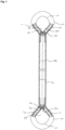
- a round sling 1 according to the invention for use on load-bearing means has a first protective tube 2 partially enclosing it to form a sling, wherein end regions of the round sling 1 are not enclosed by the first protective tube 2 and the end regions therefore form loops 4, 4' .
- a surrounding band 5, 5' is arranged as a loop reinforcement.
- the respective surrounding band 5, 5' rests loosely on an outer surface 6 of the respective loop 4, 4' of the round sling 1 and is thus placed around the loop without further fastening.
- the respective surrounding band 5, 5' is connected to the first protective tube 2 at the ends 3, 3' according to the Fig. 1 and 2 sewn twice at a distance so that the respective enclosing band 5, 5' also forms a loop.
- an openable second protective tube 7, 7' is arranged on the respective loops 4, 4' , which encloses an area of the round sling 1 on which a suspension element can be arranged and almost completely covers the respective enclosing band 5, 5' and thus locks it in place.
- a closure area of the second protective tube 7, 7' is located outside of a contact surface with the suspension element when this is functionally connected to the round sling 1. The closure area is therefore not exposed to any direct stress from the suspension element.
- An openable third protective tube 8 is arranged above the first protective tube 2 , which essentially encloses the first protective tube 2 , i.e. covers it in its longitudinal direction.
- a Velcro fastener is provided as a connecting means for the openable second and third protective tubes 7, 7' and 8 .
- the closure 9 is arranged at the respective ends 3, 3' of the first protective tube 2 and the third protective tube 8.
- the closure 9 passes through the loop interior 10 when it is functionally closed. This prevents it from being pulled off the round sling 1.
- the closure 9 is formed by two detachable straps arranged at the ends 3, 3', each with a belt clamp, with the closure 9 penetrating the first protective tube 2 and the third protective tube 8 at slots provided for this purpose.
Landscapes
- Engineering & Computer Science (AREA)
- Mechanical Engineering (AREA)
- Load-Engaging Elements For Cranes (AREA)
Claims (8)
- Élingue ronde (1) avec une première gaine de protection (2) entourant partiellement l'élingue ronde (1), des zones d'extrémité de l'élingue ronde (1) n'étant pas entourées par la première gaine de protection (2) et les zones d'extrémité formant des boucles (4), caractérisée en ce que sur la première gaine de protection (2), à ses extrémités respectives (3), en direction des boucles (4), est agencée au moins une bande d'entourage (5) qui s'applique contre une surface extérieure (6) de la boucle respective (4) de l'élingue ronde (1) et, sur les boucles respectives (4), est agencée respectivement une deuxième gaine de protection ouvrable (7), qui entoure la bande d'entourage (5) et donc, en quelque sorte, une zone de l'élingue ronde (1) sur laquelle un moyen porteur peut être agencé et qui recouvre entièrement ou au moins partiellement la boucle et la bande d'entourage.
- Élingue ronde (1) selon la revendication 1, dans laquelle une troisième gaine de protection ouvrable (8) est agencée au-dessus de la première gaine de protection (2) et entoure essentiellement la première gaine de protection (1).
- Élingue ronde (1) selon la revendication 1 ou 2, dans laquelle un blocage de la première ou de la première et de la troisième gaine de protection (8) est effectué au moyen d'au moins une fermeture (9) qui est agencée aux extrémités respectives (3) de la première gaine de protection (2) ou aux extrémités respectives (3) de la première et de la troisième gaine de protection (2, 8).
- Élingue ronde (1) selon la revendication 3, dans laquelle l'au moins une fermeture (9) est une section de bande.
- Élingue ronde (1) selon l'une quelconque des revendications précédentes, dans laquelle une zone de fermeture de la deuxième gaine de protection respective (7) est située à l'extérieur d'une surface de contact avec le moyen porteur.
- Élingue ronde (1) selon l'une quelconque des revendications précédentes, dans laquelle un moyen de liaison des deuxième et troisième gaines de protection (7, 8) ouvrables est une fermeture agrippante.
- Élingue ronde (1) selon l'une quelconque des revendications 3 à 6 précédentes, dans laquelle l'au moins une fermeture (9) peut être fermée de manière réversible.
- Élingue ronde (1) selon l'une quelconque des revendications 3 à 6 précédentes, dans laquelle l'au moins une fermeture (9) de la troisième gaine de protection (8) passe à travers un espace intérieur de boucle (10) lorsque l'au moins une fermeture (9) est fermée de manière fonctionnelle.
Applications Claiming Priority (2)
| Application Number | Priority Date | Filing Date | Title |
|---|---|---|---|
| DE102018005229.0A DE102018005229A1 (de) | 2018-07-03 | 2018-07-03 | Rundschlinge |
| PCT/DE2019/000174 WO2020007385A1 (fr) | 2018-07-03 | 2019-06-25 | Élingue |
Publications (3)
| Publication Number | Publication Date |
|---|---|
| EP3818005A1 EP3818005A1 (fr) | 2021-05-12 |
| EP3818005B1 true EP3818005B1 (fr) | 2024-10-30 |
| EP3818005C0 EP3818005C0 (fr) | 2024-10-30 |
Family
ID=67956429
Family Applications (1)
| Application Number | Title | Priority Date | Filing Date |
|---|---|---|---|
| EP19768998.7A Active EP3818005B1 (fr) | 2018-07-03 | 2019-06-25 | Élingue |
Country Status (3)
| Country | Link |
|---|---|
| EP (1) | EP3818005B1 (fr) |
| DE (1) | DE102018005229A1 (fr) |
| WO (1) | WO2020007385A1 (fr) |
Families Citing this family (1)
| Publication number | Priority date | Publication date | Assignee | Title |
|---|---|---|---|---|
| NL2031064B1 (en) * | 2022-02-24 | 2023-09-06 | Enduro Softslings B V | A Protective Sleeve For A Load Carrying Sling |
Family Cites Families (4)
| Publication number | Priority date | Publication date | Assignee | Title |
|---|---|---|---|---|
| GR73539B (fr) | 1980-01-21 | 1984-03-12 | Spanset Inter Ag | |
| JP3165294B2 (ja) * | 1993-07-30 | 2001-05-14 | 明大株式会社 | 高荷重用ベルトスリング |
| EP1451091B1 (fr) * | 2001-12-03 | 2011-03-02 | mamutec AG | Elingue de levage |
| US20150267347A1 (en) * | 2014-03-19 | 2015-09-24 | Charles D. Farmer | Chafe protected rope and protective cover therefore |
-
2018
- 2018-07-03 DE DE102018005229.0A patent/DE102018005229A1/de not_active Withdrawn
-
2019
- 2019-06-25 EP EP19768998.7A patent/EP3818005B1/fr active Active
- 2019-06-25 WO PCT/DE2019/000174 patent/WO2020007385A1/fr not_active Ceased
Also Published As
| Publication number | Publication date |
|---|---|
| WO2020007385A1 (fr) | 2020-01-09 |
| EP3818005C0 (fr) | 2024-10-30 |
| EP3818005A1 (fr) | 2021-05-12 |
| DE102018005229A1 (de) | 2020-01-09 |
Similar Documents
| Publication | Publication Date | Title |
|---|---|---|
| DE69622881T2 (de) | Kupplungsvorrichtung für eine kette | |
| DE102012000202B4 (de) | Vorrichtung zur Verankerung eines Gurtschlosses und Vorrichtungsanordnung mit wenigstens zwei solchen Vorrichtungen | |
| EP3818005B1 (fr) | Élingue | |
| EP1791777B2 (fr) | Element de protection pour systemes d'amarrage ou de blocage textiles et systemes d'amarrage ou de blocage equipes d'un tel element de protection | |
| EP1456559B1 (fr) | Moyen d`accrochage | |
| DE102014208819A1 (de) | Ringelement mit einem geteilten Sockel für ein Zurr- oder Anschlagmittel | |
| DE102009050078A1 (de) | Kettenverbindungsglied | |
| EP2855204B1 (fr) | Moyen d'absorption de traction | |
| DE2240013A1 (de) | Kupplungsstab | |
| DE20121118U1 (de) | Anschlagmittel | |
| DE102017209004B4 (de) | Gleichlaufgelenk in Faserverbundbauweise | |
| EP1223140B1 (fr) | Dispositif de suspension pour régler continuellement la longueur d' un sangle de levage | |
| DE102014002228A1 (de) | Haltevorrichtung | |
| DE20211100U1 (de) | Gliederkette mit codierten Kettengliedern | |
| EP4046953B1 (fr) | Système modulaire de suspension à un crochet de grue ou à un point d'ancrage ou à un point d'arrimage | |
| DE3324095A1 (de) | Buendelhebegeschirr fuer langgueter | |
| DE202023105734U1 (de) | Vorrichtung zur Anbringung an einer textilen Kette | |
| EP3742021B1 (fr) | Griffe de raccourcissement permettant de serrer une chaîne d'amarrage | |
| DE102021117790B4 (de) | Artikel, Verfahren zur Herstellung einer Sicherungsvorrichtung, Verwendung der Sicherungsvorrichtung und Sicherungsvorrichtung | |
| DE29509959U1 (de) | Gurt zur Befestigung eines Gegenstandes, insbesondere eines Netzes | |
| DE1756317A1 (de) | Hebeband bzw. Ladeband | |
| DE925150C (de) | Abschleppseil, insbesondere fuer Kraftfahrzeuge | |
| DE10338646B4 (de) | Plattenförmiges Verbindungselement | |
| DE202014001493U1 (de) | Haltevorrichtung | |
| DE202018104568U1 (de) | Verbindungselement für Gepäckseil und Gepäckseil |
Legal Events
| Date | Code | Title | Description |
|---|---|---|---|
| STAA | Information on the status of an ep patent application or granted ep patent |
Free format text: STATUS: UNKNOWN |
|
| STAA | Information on the status of an ep patent application or granted ep patent |
Free format text: STATUS: THE INTERNATIONAL PUBLICATION HAS BEEN MADE |
|
| PUAI | Public reference made under article 153(3) epc to a published international application that has entered the european phase |
Free format text: ORIGINAL CODE: 0009012 |
|
| STAA | Information on the status of an ep patent application or granted ep patent |
Free format text: STATUS: REQUEST FOR EXAMINATION WAS MADE |
|
| 17P | Request for examination filed |
Effective date: 20201230 |
|
| AK | Designated contracting states |
Kind code of ref document: A1 Designated state(s): AL AT BE BG CH CY CZ DE DK EE ES FI FR GB GR HR HU IE IS IT LI LT LU LV MC MK MT NL NO PL PT RO RS SE SI SK SM TR |
|
| DAV | Request for validation of the european patent (deleted) | ||
| DAX | Request for extension of the european patent (deleted) | ||
| RAP3 | Party data changed (applicant data changed or rights of an application transferred) |
Owner name: SPAN SET GESELLSCHAFT FUER TRANSPORTSYSTEME UND TECHNISCHE BAENDER MIT BESCHRAENKTER HAFTUNG & CO. KOMMANDITGESELLSCHAFT |
|
| GRAP | Despatch of communication of intention to grant a patent |
Free format text: ORIGINAL CODE: EPIDOSNIGR1 |
|
| STAA | Information on the status of an ep patent application or granted ep patent |
Free format text: STATUS: GRANT OF PATENT IS INTENDED |
|
| INTG | Intention to grant announced |
Effective date: 20240606 |
|
| GRAS | Grant fee paid |
Free format text: ORIGINAL CODE: EPIDOSNIGR3 |
|
| GRAA | (expected) grant |
Free format text: ORIGINAL CODE: 0009210 |
|
| STAA | Information on the status of an ep patent application or granted ep patent |
Free format text: STATUS: THE PATENT HAS BEEN GRANTED |
|
| AK | Designated contracting states |
Kind code of ref document: B1 Designated state(s): AL AT BE BG CH CY CZ DE DK EE ES FI FR GB GR HR HU IE IS IT LI LT LU LV MC MK MT NL NO PL PT RO RS SE SI SK SM TR |
|
| REG | Reference to a national code |
Ref country code: GB Ref legal event code: FG4D Free format text: NOT ENGLISH |
|
| REG | Reference to a national code |
Ref country code: CH Ref legal event code: EP |
|
| REG | Reference to a national code |
Ref country code: DE Ref legal event code: R096 Ref document number: 502019012403 Country of ref document: DE |
|
| REG | Reference to a national code |
Ref country code: IE Ref legal event code: FG4D Free format text: LANGUAGE OF EP DOCUMENT: GERMAN |
|
| U01 | Request for unitary effect filed |
Effective date: 20241118 |
|
| U07 | Unitary effect registered |
Designated state(s): AT BE BG DE DK EE FI FR IT LT LU LV MT NL PT RO SE SI Effective date: 20241122 |
|
| PG25 | Lapsed in a contracting state [announced via postgrant information from national office to epo] |
Ref country code: IS Free format text: LAPSE BECAUSE OF FAILURE TO SUBMIT A TRANSLATION OF THE DESCRIPTION OR TO PAY THE FEE WITHIN THE PRESCRIBED TIME-LIMIT Effective date: 20250228 Ref country code: HR Free format text: LAPSE BECAUSE OF FAILURE TO SUBMIT A TRANSLATION OF THE DESCRIPTION OR TO PAY THE FEE WITHIN THE PRESCRIBED TIME-LIMIT Effective date: 20241030 |
|
| PG25 | Lapsed in a contracting state [announced via postgrant information from national office to epo] |
Ref country code: ES Free format text: LAPSE BECAUSE OF FAILURE TO SUBMIT A TRANSLATION OF THE DESCRIPTION OR TO PAY THE FEE WITHIN THE PRESCRIBED TIME-LIMIT Effective date: 20241030 |
|
| PG25 | Lapsed in a contracting state [announced via postgrant information from national office to epo] |
Ref country code: NO Free format text: LAPSE BECAUSE OF FAILURE TO SUBMIT A TRANSLATION OF THE DESCRIPTION OR TO PAY THE FEE WITHIN THE PRESCRIBED TIME-LIMIT Effective date: 20250130 |
|
| PG25 | Lapsed in a contracting state [announced via postgrant information from national office to epo] |
Ref country code: GR Free format text: LAPSE BECAUSE OF FAILURE TO SUBMIT A TRANSLATION OF THE DESCRIPTION OR TO PAY THE FEE WITHIN THE PRESCRIBED TIME-LIMIT Effective date: 20250131 |
|
| PG25 | Lapsed in a contracting state [announced via postgrant information from national office to epo] |
Ref country code: PL Free format text: LAPSE BECAUSE OF FAILURE TO SUBMIT A TRANSLATION OF THE DESCRIPTION OR TO PAY THE FEE WITHIN THE PRESCRIBED TIME-LIMIT Effective date: 20241030 |
|
| PG25 | Lapsed in a contracting state [announced via postgrant information from national office to epo] |
Ref country code: RS Free format text: LAPSE BECAUSE OF FAILURE TO SUBMIT A TRANSLATION OF THE DESCRIPTION OR TO PAY THE FEE WITHIN THE PRESCRIBED TIME-LIMIT Effective date: 20250130 |
|
| PG25 | Lapsed in a contracting state [announced via postgrant information from national office to epo] |
Ref country code: SM Free format text: LAPSE BECAUSE OF FAILURE TO SUBMIT A TRANSLATION OF THE DESCRIPTION OR TO PAY THE FEE WITHIN THE PRESCRIBED TIME-LIMIT Effective date: 20241030 |
|
| U20 | Renewal fee for the european patent with unitary effect paid |
Year of fee payment: 7 Effective date: 20250606 |
|
| PG25 | Lapsed in a contracting state [announced via postgrant information from national office to epo] |
Ref country code: SK Free format text: LAPSE BECAUSE OF FAILURE TO SUBMIT A TRANSLATION OF THE DESCRIPTION OR TO PAY THE FEE WITHIN THE PRESCRIBED TIME-LIMIT Effective date: 20241030 |
|
| PG25 | Lapsed in a contracting state [announced via postgrant information from national office to epo] |
Ref country code: CZ Free format text: LAPSE BECAUSE OF FAILURE TO SUBMIT A TRANSLATION OF THE DESCRIPTION OR TO PAY THE FEE WITHIN THE PRESCRIBED TIME-LIMIT Effective date: 20241030 |
|
| PLBE | No opposition filed within time limit |
Free format text: ORIGINAL CODE: 0009261 |
|
| STAA | Information on the status of an ep patent application or granted ep patent |
Free format text: STATUS: NO OPPOSITION FILED WITHIN TIME LIMIT |
|
| 26N | No opposition filed |
Effective date: 20250731 |
|
| REG | Reference to a national code |
Ref country code: CH Ref legal event code: H13 Free format text: ST27 STATUS EVENT CODE: U-0-0-H10-H13 (AS PROVIDED BY THE NATIONAL OFFICE) Effective date: 20260127 |
|
| PG25 | Lapsed in a contracting state [announced via postgrant information from national office to epo] |
Ref country code: MC Free format text: LAPSE BECAUSE OF FAILURE TO SUBMIT A TRANSLATION OF THE DESCRIPTION OR TO PAY THE FEE WITHIN THE PRESCRIBED TIME-LIMIT Effective date: 20241030 |
|
| GBPC | Gb: european patent ceased through non-payment of renewal fee |
Effective date: 20250625 |
|
| PG25 | Lapsed in a contracting state [announced via postgrant information from national office to epo] |
Ref country code: GB Free format text: LAPSE BECAUSE OF NON-PAYMENT OF DUE FEES Effective date: 20250625 |
|
| PG25 | Lapsed in a contracting state [announced via postgrant information from national office to epo] |
Ref country code: IE Free format text: LAPSE BECAUSE OF NON-PAYMENT OF DUE FEES Effective date: 20250625 |
|
| PG25 | Lapsed in a contracting state [announced via postgrant information from national office to epo] |
Ref country code: CH Free format text: LAPSE BECAUSE OF NON-PAYMENT OF DUE FEES Effective date: 20250630 |