EP3818249B1 - Verfahren und vorrichtungen zur leistungssteuerung in bergbaumaschinen - Google Patents
Verfahren und vorrichtungen zur leistungssteuerung in bergbaumaschinen Download PDFInfo
- Publication number
- EP3818249B1 EP3818249B1 EP19736839.2A EP19736839A EP3818249B1 EP 3818249 B1 EP3818249 B1 EP 3818249B1 EP 19736839 A EP19736839 A EP 19736839A EP 3818249 B1 EP3818249 B1 EP 3818249B1
- Authority
- EP
- European Patent Office
- Prior art keywords
- electric power
- mining machine
- power
- units
- bus
- Prior art date
- Legal status (The legal status is an assumption and is not a legal conclusion. Google has not performed a legal analysis and makes no representation as to the accuracy of the status listed.)
- Active
Links
Images

Classifications
-
- B—PERFORMING OPERATIONS; TRANSPORTING
- B60—VEHICLES IN GENERAL
- B60L—PROPULSION OF ELECTRICALLY-PROPELLED VEHICLES; SUPPLYING ELECTRIC POWER FOR AUXILIARY EQUIPMENT OF ELECTRICALLY-PROPELLED VEHICLES; ELECTRODYNAMIC BRAKE SYSTEMS FOR VEHICLES IN GENERAL; MAGNETIC SUSPENSION OR LEVITATION FOR VEHICLES; MONITORING OPERATING VARIABLES OF ELECTRICALLY-PROPELLED VEHICLES; ELECTRIC SAFETY DEVICES FOR ELECTRICALLY-PROPELLED VEHICLES
- B60L15/00—Methods, circuits, or devices for controlling the traction-motor speed of electrically-propelled vehicles
- B60L15/20—Methods, circuits, or devices for controlling the traction-motor speed of electrically-propelled vehicles for control of the vehicle or its driving motor to achieve a desired performance, e.g. speed, torque, programmed variation of speed
- B60L15/2045—Methods, circuits, or devices for controlling the traction-motor speed of electrically-propelled vehicles for control of the vehicle or its driving motor to achieve a desired performance, e.g. speed, torque, programmed variation of speed for optimising the use of energy
-
- B—PERFORMING OPERATIONS; TRANSPORTING
- B60—VEHICLES IN GENERAL
- B60L—PROPULSION OF ELECTRICALLY-PROPELLED VEHICLES; SUPPLYING ELECTRIC POWER FOR AUXILIARY EQUIPMENT OF ELECTRICALLY-PROPELLED VEHICLES; ELECTRODYNAMIC BRAKE SYSTEMS FOR VEHICLES IN GENERAL; MAGNETIC SUSPENSION OR LEVITATION FOR VEHICLES; MONITORING OPERATING VARIABLES OF ELECTRICALLY-PROPELLED VEHICLES; ELECTRIC SAFETY DEVICES FOR ELECTRICALLY-PROPELLED VEHICLES
- B60L58/00—Methods or circuit arrangements for monitoring or controlling batteries or fuel cells, specially adapted for electric vehicles
- B60L58/10—Methods or circuit arrangements for monitoring or controlling batteries or fuel cells, specially adapted for electric vehicles for monitoring or controlling batteries
- B60L58/18—Methods or circuit arrangements for monitoring or controlling batteries or fuel cells, specially adapted for electric vehicles for monitoring or controlling batteries of two or more battery modules
-
- E—FIXED CONSTRUCTIONS
- E21—EARTH OR ROCK DRILLING; MINING
- E21F—SAFETY DEVICES, TRANSPORT, FILLING-UP, RESCUE, VENTILATION, OR DRAINING IN OR OF MINES OR TUNNELS
- E21F13/00—Transport specially adapted to underground conditions
-
- E—FIXED CONSTRUCTIONS
- E21—EARTH OR ROCK DRILLING; MINING
- E21F—SAFETY DEVICES, TRANSPORT, FILLING-UP, RESCUE, VENTILATION, OR DRAINING IN OR OF MINES OR TUNNELS
- E21F17/00—Methods or devices for use in mines or tunnels, not covered elsewhere
- E21F17/04—Distributing means for power supply in mines
- E21F17/06—Distributing electric power; Cable networks; Conduits for cables
-
- H—ELECTRICITY
- H02—GENERATION; CONVERSION OR DISTRIBUTION OF ELECTRIC POWER
- H02J—ELECTRIC POWER NETWORKS; CIRCUIT ARRANGEMENTS OR SYSTEMS FOR SUPPLYING OR DISTRIBUTING ELECTRIC POWER; SYSTEMS FOR STORING ELECTRIC ENERGY
- H02J1/00—Circuit arrangements for DC mains or DC distribution networks
- H02J1/14—Balancing load and power generation in DC networks
- H02J1/15—Balancing load and power generation in DC networks characterised by load management
-
- E—FIXED CONSTRUCTIONS
- E21—EARTH OR ROCK DRILLING; MINING
- E21F—SAFETY DEVICES, TRANSPORT, FILLING-UP, RESCUE, VENTILATION, OR DRAINING IN OR OF MINES OR TUNNELS
- E21F1/00—Ventilation of mines or tunnels; Distribution of ventilating currents
-
- E—FIXED CONSTRUCTIONS
- E21—EARTH OR ROCK DRILLING; MINING
- E21F—SAFETY DEVICES, TRANSPORT, FILLING-UP, RESCUE, VENTILATION, OR DRAINING IN OR OF MINES OR TUNNELS
- E21F17/00—Methods or devices for use in mines or tunnels, not covered elsewhere
-
- H—ELECTRICITY
- H02—GENERATION; CONVERSION OR DISTRIBUTION OF ELECTRIC POWER
- H02J—ELECTRIC POWER NETWORKS; CIRCUIT ARRANGEMENTS OR SYSTEMS FOR SUPPLYING OR DISTRIBUTING ELECTRIC POWER; SYSTEMS FOR STORING ELECTRIC ENERGY
- H02J2207/00—Details of circuit arrangements for charging or discharging batteries or supplying loads from batteries
- H02J2207/30—Charge provided using DC bus or data bus of a computer
-
- H—ELECTRICITY
- H02—GENERATION; CONVERSION OR DISTRIBUTION OF ELECTRIC POWER
- H02J—ELECTRIC POWER NETWORKS; CIRCUIT ARRANGEMENTS OR SYSTEMS FOR SUPPLYING OR DISTRIBUTING ELECTRIC POWER; SYSTEMS FOR STORING ELECTRIC ENERGY
- H02J7/00—Circuit arrangements for charging or discharging batteries or for supplying loads from batteries
- H02J7/14—Circuit arrangements for charging or discharging batteries or for supplying loads from batteries for charging batteries from dynamo-electric generators driven at varying speed, e.g. on vehicle
- H02J7/1438—Circuit arrangements for charging or discharging batteries or for supplying loads from batteries for charging batteries from dynamo-electric generators driven at varying speed, e.g. on vehicle in combination with power supplies for loads other than batteries
-
- H—ELECTRICITY
- H02—GENERATION; CONVERSION OR DISTRIBUTION OF ELECTRIC POWER
- H02J—ELECTRIC POWER NETWORKS; CIRCUIT ARRANGEMENTS OR SYSTEMS FOR SUPPLYING OR DISTRIBUTING ELECTRIC POWER; SYSTEMS FOR STORING ELECTRIC ENERGY
- H02J7/00—Circuit arrangements for charging or discharging batteries or for supplying loads from batteries
- H02J7/14—Circuit arrangements for charging or discharging batteries or for supplying loads from batteries for charging batteries from dynamo-electric generators driven at varying speed, e.g. on vehicle
- H02J7/1446—Circuit arrangements for charging or discharging batteries or for supplying loads from batteries for charging batteries from dynamo-electric generators driven at varying speed, e.g. on vehicle in response to parameters of a vehicle
-
- Y—GENERAL TAGGING OF NEW TECHNOLOGICAL DEVELOPMENTS; GENERAL TAGGING OF CROSS-SECTIONAL TECHNOLOGIES SPANNING OVER SEVERAL SECTIONS OF THE IPC; TECHNICAL SUBJECTS COVERED BY FORMER USPC CROSS-REFERENCE ART COLLECTIONS [XRACs] AND DIGESTS
- Y02—TECHNOLOGIES OR APPLICATIONS FOR MITIGATION OR ADAPTATION AGAINST CLIMATE CHANGE
- Y02T—CLIMATE CHANGE MITIGATION TECHNOLOGIES RELATED TO TRANSPORTATION
- Y02T10/00—Road transport of goods or passengers
- Y02T10/60—Other road transportation technologies with climate change mitigation effect
- Y02T10/72—Electric energy management in electromobility
-
- Y—GENERAL TAGGING OF NEW TECHNOLOGICAL DEVELOPMENTS; GENERAL TAGGING OF CROSS-SECTIONAL TECHNOLOGIES SPANNING OVER SEVERAL SECTIONS OF THE IPC; TECHNICAL SUBJECTS COVERED BY FORMER USPC CROSS-REFERENCE ART COLLECTIONS [XRACs] AND DIGESTS
- Y02—TECHNOLOGIES OR APPLICATIONS FOR MITIGATION OR ADAPTATION AGAINST CLIMATE CHANGE
- Y02T—CLIMATE CHANGE MITIGATION TECHNOLOGIES RELATED TO TRANSPORTATION
- Y02T10/00—Road transport of goods or passengers
- Y02T10/80—Technologies aiming to reduce greenhouse gasses emissions common to all road transportation technologies
- Y02T10/92—Energy efficient charging or discharging systems for batteries, ultracapacitors, supercapacitors or double-layer capacitors specially adapted for vehicles
Definitions
- the present disclosure relates to methods and devices for power control in mining machines.
- the disclosure relates to methods and devices for power control of a mining machine that comprises one or more energy sources.
- the disclosure also relates to corresponding computer programs and a mining machine comprising power control circuitry/arrangement.
- the day-to-day operations of mining typically involve cycles of drilling, blasting, ventilating, and loading, hauling and dumping material that has been freed in the process.
- the mining operations involve a wide variety of mining machines, such as face drill rigs, production drill rigs, rock bolting rigs, cable bolting rigs, concrete spraying machines, loaders, haulers and dumpers.
- face drill rigs production drill rigs
- rock bolting rigs rock bolting rigs
- cable bolting rigs concrete spraying machines
- loaders haulers and dumpers.
- the listed mining machines require considerable power during operation. There is currently considerable effort in switching from fuel-powered mining machines to electrically and battery powered mining machines.
- the mining cycle places demands on power that are unique to mining.
- the mining machines often have very high power demands during predictable phases of a mining cycle.
- the source providing power to the mining machine(s) is stressed and there is a risk of an unwanted stop in production due to power demand overload.
- a loss of steering/control of a mining machine due to power failure could result in danger to mining personnel and the mining machines.
- Each mining machine typically has a plurality of electric power units, each with specific electric power needs.
- a particular challenge is that some of the electric power units have predictable power demands, while others are affected by external forces, such as electric power demands of hydraulics, making power peaks difficult or impossible to predict. Power peaks may stress the energy source of the mining machine and cause interruptions, e.g. due to some electric power units not getting sufficient power, which may lead to a reduction in productivity and potential dangers.
- the stress of the high power demands may significantly impact the life expectancy of the energy source as well as the mining machine as a whole.
- WO 2011/109050 A2 discloses an electric drive system for a vehicle, e.g., mining vehicle, controlling power distribution based on catenary line connectivity and operational priorities.
- An object of the present disclosure is to provide methods and devices which seek to mitigate, alleviate, or eliminate one or more of the above-identified deficiencies in the art and disadvantages singly or in any combination and to provide methods, computer programs, control circuitry and mining machines for power control of a mining machine.
- the present disclosure relates to a method for power control of a mining machine.
- the mining machine comprising one or more energy sources.
- the method comprises assigning priorities to electric power units of a plurality of electric power units of the mining machine, each electric power unit having an assigned priority.
- the method further comprises controlling electric power distribution for the plurality of electric power units based on the assigned priorities.
- the one or more energy sources comprise at least one of a rechargeable battery, a supercapacitor, a rechargeable fuel cell and a flywheel.
- the same mining machine may face a set of tasks, each task placing different power level demands on different electric power units of the mining machine.
- the electric power units can be organized to solve the current task at hand given the available power.
- all available power can be used for a specific electrical power unit as long as a higher prioritized electric power unit is not used.
- all available electric power can be used for traction - to maximize vehicle speed - as long as the higher prioritized steering, driven by an auxiliary motor, is not used.
- the method enables increased productivity, improved reliability, improved safety and enables prolonged life expectancy of the mining machine, in particular the rechargeable battery in case of a battery powered mining machine.
- the disclosed method provides a systematic way of handling the charge and discharge power levels of the battery.
- the step of controlling electric power distribution is further based on a maximum charge power level and a maximum discharge power level of a direct current, DC, bus of the mining machine.
- the DC-bus is configured to transmit and receive electric power to/from the one or more energy sources, such as a rechargeable battery, and the plurality of electric power units.
- a battery has limited charging and discharging power levels that may not be exceeded.
- the maximum charge power levels and maximum discharge power levels are based on a desired state of charge, SoC, of the rechargeable battery. According to some aspects, the maximum charge power levels and maximum discharge power levels are based on a temperature of the rechargeable battery.
- the rechargeable battery will typically continuously send charge and discharge limits to the control circuitry of the mining machine as part of determining the charge and discharge limits of the plurality of electric power units of the mining machine.
- the discharge limits are typically based on a desired state of charge of the battery, but may be based on other parameters, such as battery temperature and/or battery temperature change, as well.
- the discharge limits may also be based on any combination of said, and/or other appropriate, parameters. Likewise for corresponding charge limits.
- the step of controlling power distribution is further based on respective maximum charge power levels and respective maximum discharge power levels of the plurality of electric power units of the mining machine.
- the electrical power units will typically interact together with the one or more energy sources, such as a battery, in order to determine possible charge and discharge power levels for the electric power units. It is not only the one or more energy sources that determines how much electric power an electric power unit may discharge; other energy power units may also affect the decision. Charge and discharge limits can thereby be separated but coordinated with each other.
- the maximum charge power level and maximum discharge power level of an electrical power unit is based on a remaining DC-bus charge power and/or a remaining DC-bus discharge power, and further based on a predetermined power margin.
- Auxiliary electric power units such as an auxiliary motor, may thereby assign the power limits of the electrical power unit in question based on the remaining DC-bus (dis)charge power and a power margin. This guarantees that certain power limits are not exceeded by more than said power margin.
- the step of controlling power distribution is further based on a voltage level of a DC-bus of the mining machine, wherein the DC-bus is configured to transmit and receive electric power to/from the rechargeable battery and the plurality of electric power units. Different power units may then adjust their power levels based on different voltage levels. This may be particularly suitable when a DC-bus of the mining machine is supplied via e.g. an alternating current, AC, direct current, DC, converter having a constant nominal voltage level.
- the assigned priorities are separated into priorities for charging electric power units and priorities for discharging electric power units.
- priorities for charging and discharging electric power units By assigning different priorities for charging and discharging electric power units the risk for dangerous stops, e.g. due to loss of control of the mining machine, can be significantly reduced. For instance, critical 24 V peripheral power systems, which typically require relatively low power levels, can be ensured to always have sufficient power.
- a set of electric power units are grouped together in a functional unit and assigned a single priority for the functional unit.
- the functional unit of electric power units comprises a charger, a brake chopper and a retarder.
- certain electric power units e.g. an onboard charger and a brake chopper/retarder, will never be activated simultaneously. Therefore, physical units dedicated to charging or discharging, such as (onboard) chargers, brake choppers and retarders, can be treated as a single functional unit.
- the step of controlling power distribution is further based on measured power produced and consumed in each electric power unit.
- the step of controlling power distribution further comprises determining power estimation errors for at least one of the plurality of electric power units based on electric power distribution feedback from one or more energy sources of the mining machine.
- the step of controlling power distribution further comprises adjusting a charging and/or a discharging power level of the at least one of the plurality of electric power units based on the determined power estimation errors.
- the present disclosure further relates to a computer program for power control of a mining machine, the computer program comprising computer program code which, when executed, causes control circuitry of a mining machine to carry out the method for power control of a mining machine, as described above and below.
- the present disclosure also relates to control circuitry for power control of a mining machine.
- the control circuitry is configured to assign priorities to electric power units of a plurality of electric power units of the mining machine. Each electric power unit has an assigned priority.
- the control circuitry is further configured to control power distribution for the plurality of electric power units based on the assigned priorities.
- control circuitry further comprises a processor and a memory.
- the memory has a computer program for power control of a mining machine, as described above and below, stored thereon.
- the processor is configured to execute the computer program.
- the present disclosure further relates to a mining machine for power control of a mining machine.
- the mining machine comprises one or more energy sources, a plurality of electric power units and control circuitry.
- the mining machine is configured to transmit and receive electric power to/from the one or more energy sources and the plurality of electric power units.
- the control circuitry is configured to assign priorities to electric power units of a plurality of electric power units of the mining machine, each electric power unit having an assigned priority.
- the control circuit is further configured to control power distribution for the plurality of electric power units based on the assigned priorities.
- the one or more energy sources comprises at least one of a rechargeable battery, a supercapacitor, a rechargeable fuel cell and a flywheel.
- the mining machine also comprises a DC-bus.
- the DC-bus is configured to transmit and receive electric power to/from the one or more energy sources and the plurality of electric power units.
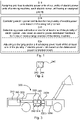
- FIG. 1 is a flowchart illustrating a method for power control of a mining machine.
- the mining machine 300 comprises one or more energy sources 310, which is electrically connected to a set of electric power units 320a-c.
- the one or more energy sources are typically connected to the electric power units via a direct current, DC, bus 330.
- the mining machine 300 further comprises control circuitry 340 configured to carry out the disclosed method.
- the control circuitry may comprise a computer program configured to carry out the disclosed method when executed. While the DC-bus 330 is discussed as a separate unit, it may be comprised in the control circuitry.
- the method enables systematic prioritization among an arbitrary number of electric power units connected to one or more energy sources, herein illustrated by a rechargeable battery.
- the one or more energy sources are not limited to rechargeable batteries only; the one or more energy sources may comprise one or more of a rechargeable battery, a supercapacitor, a rechargeable fuel cell and a flywheel.
- the one or more energy sources may be of the same type, e.g. only rechargeable batteries, or of different types. In other words, the one or more energy sources may comprise at least two different types of energy sources.
- These rechargeable energy sources enable sufficient energy storage with respect to weight and operational demands, while also being able to provide the necessary power output during discharge.
- the method is a method for power control of a mining machine.
- the mining machine comprises one or more energy sources.
- One purpose of the disclosed method is to stay within the charging and discharging limits of the one or more energy sources and thereby avoid downtime.
- the method comprises assigning S10 priorities to electric power units of a plurality of electric power units of the mining machine, each electric power unit having an assigned priority.
- the method further comprises controlling S20 electric power distribution for the plurality of electric power units based on the assigned priorities.
- the battery typically supplies electric power via a DC-bus to electric power units of the mining machine. The starting point is then to determine how much the DC-bus is allowed to be charged and discharged.
- the step of controlling S20 electric power distribution is further based on a maximum charge power level and a maximum discharge power level of a DC-bus of the mining machine.
- the DC-bus is configured to transmit and receive electric power to/from the one or more energy sources, here illustrated by a rechargeable battery, and the plurality of electric power units.
- a particular strength of the disclosed method is that it enables providing each electric power unit with individual charge and discharge priorities.
- the assigned priorities are separated into priorities for charging electric power units and priorities for discharging electric power units.
- the separation into charge and discharge priorities is particularly effective at ensuring that critical electrical power units always have power, which reduces the risk of dangerous interruptions or stops, e.g. due to loss of control of the mining machine.
- the step of controlling S20 electric power distribution is further based on respective maximum charge power levels and respective maximum discharge power levels of the plurality of electric power units of the mining machine.
- the electric power of the electric power units will be limited according to an assigned priority of the electric power units by subtracting the current or expected electric power of the electric power units.
- the electric power unit having the lowest priority will have its electric power reduced first.
- the maximum charge power levels and maximum discharge power levels are based on a desired state of charge, SoC, of the rechargeable battery. According to some aspects, the maximum charge power levels and maximum discharge power levels are based on a temperature of the rechargeable battery.
- Certain electric power units may have antagonistic relationships when it comes to charging and discharging.
- the set of electric power units comprises a charger, a brake chopper and a retarder. It does not makes sense to use an onboard charger at the same time as a brake chopper or a retarder.
- These electric power units may therefore be grouped into a single functional unit, even though they are physically separate units.
- a set of electric power units are grouped together in a functional unit and assigned a single priority for the functional unit.
- the maximum charge/discharge power level of the DC-bus will determine the available power for the highest priority electrical power unit (or units if having separate priorities for charging and discharging), and implicitly the available power for the electrical power units of lower priority(-ies).
- the maximum charge/discharge power level of the DC-bus does not depend only on the battery, however, but also on the electric power units.
- the DC-bus charge/discharge limit will be determined by a difference between the battery power charge/discharge limit and the demands of the electrical power units.
- the step of controlling S20 electric power distribution is further based on measured power produced and consumed in each electric power unit. By introducing a power charge/discharge power margin as a virtual electrical power unit, a robustness can be added to the electric power control method.
- the control of the electric power distribution may be performed sequentially, wherein the electric power unit having the highest priority gets its demand met first, before any power is provided to electric power units assigned lower priorities.
- the maximum charge/discharge power level of the DC-bus may include measurement errors, determining downstream maximum charge/discharge power levels of the electric power units may be adversely affected.
- the step of controlling S20 electric power distribution further comprises determining S22 power estimation errors for at least one of the plurality of electric power units based on electric power distribution feedback from the one or more energy sources.
- the step of controlling power distribution further comprises adjusting S24 a charging and/or a discharging power level of the at least one of the plurality of electric power units based on the determined power estimation errors.
- the charge and discharge power limits of plurality of electric power units are continuously updated. According to some aspects, the charge and discharge power limits are updated at a predetermined frequency. Likewise, the charge and discharge electric power limits of the DC-bus may be continuously updated, e.g. at a predetermined frequency. The electric power charge and discharge limits of the DC-bus as well as the individual electric power charge and discharge limits of the plurality of electric power units may be based on continuous updates, e.g. at a predetermined frequency, of the electric power charge and discharge demands of the plurality of electric power units. In other words, the electric power charge and discharge demands may be used in a feedback loop in order to continuously update the electric power charge and discharge limits of the DC-bus and/or the plurality of electric power units.
- the step of controlling S20 electric power distribution is further based on a voltage level of a DC-bus of the mining machine, wherein the DC-bus is configured to transmit and receive electric power to/from at least one of a rechargeable battery, a supercapacitor, a rechargeable fuel cell and a flywheel of the mining machine and the plurality of electric power units.
- auxiliary electric power units such as a speed controlled auxiliary motor
- an alternative or complementary aspects exists, which is based on assigning the respective charge/discharge power limits of the auxiliary electric power unit based on a remaining DC-bus charge/discharge plus a margin.
- This has an advantage in that it guarantees that the electric power limits of the battery are not exceeded by more than said margin.
- the maximum charge power level and maximum discharge power level of an electrical power unit is based on a remaining DC-bus charge power and/or a remaining DC-bus discharge power, and further based on a predetermined power margin.
- the present disclosure further relates to a computer program for power control of a mining machine, the computer program comprising computer program code which, when executed, causes control circuitry of a mining machine to carry out the method for power control of a mining machine, as described above and below.
- Figure 2 illustrates control circuitry 240 for power control of a mining machine.
- the control circuitry 240 is configured to assign priorities to electric power units of a plurality of electric power units of the mining machine, each electric power unit having an assigned priority.
- the control circuitry is further configured to control power distribution for the plurality of electric power units based on the assigned priorities.
- the control circuitry 240 further comprises a processor 242 and a memory 244.
- the memory 244 has a computer program as described above and below stored thereon.
- the processor 242 is configured to execute the computer program.
- the control circuitry may additionally comprise a DC-bus.
- the DC-bus is configured to transmit and receive electric power to/from one or more energy sources of the mining machine, such as a rechargeable battery, and the plurality of electric power units.
- the operation of mining machines may be performed either from the mining machine itself or via remote control.
- the operational control of the mining machine is typically performed by a machine control unit, which may be comprised in the mining machine or be located external to the mining machine, e.g. as part of a central control system.
- the machine control unit is configured to control one or more electrical systems and/or subsystems of the mining machine.
- the machine control unit may be an embedded system.
- the control circuitry may be part of such a machine control unit.
- the control circuitry implements the disclosed method and thus has all the associated technical effects and advantages.
- FIG. 3 illustrates a mining machine according to the present disclosure.
- the mining machine 300 comprises one or more energy sources 310.
- the one or more energy sources 310 comprise a rechargeable battery.
- the mining machine further comprises one or more battery management systems, BMS, 360 configured to provide battery data to control circuitry 340 of the mining machine.
- the battery data may comprise an operational status of the battery, such as a charge level or a temperature of the battery.
- the one or more energy sources are not limited to batteries only; the one or more energy sources may be one of a rechargeable battery, a supercapacitor, a rechargeable fuel cell and a flywheel, or any combination thereof.
- the mining machine has a hybrid energy supply, i.e. the mining machine comprises at least two different types of energy sources.
- the mining machine may comprise a diesel powered energy source and a rechargeable battery.
- the diesel powered energy source may further be configured to charge the rechargeable battery.
- the mining machine may comprise one or more battery management systems for monitoring the operational status of the batteries and provide the control circuitry with battery data
- the mining machine may comprise corresponding energy source management systems for supercapacitors, rechargeable fuel cells, flywheels and hybrid energy sources.
- the energy source management systems will be configured to provide the control circuitry with data relevant for the respective energy source, e.g. kinetic energy of a flywheel.
- the mining machine further comprises a plurality of electric power units 320a, 320b, 320c.
- the mining machine is configured to transmit and receive electric power to/from the one or more energy sources and the plurality of electric power units.
- the mining machine also comprises a DC-bus 330.
- the DC-bus is configured to transmit and receive electric power to/from the one or more energy sources and the plurality of electric power units.
- the mining machine additionally comprises control circuitry 340.
- the control circuitry is configured to assign priorities to electric power units of a plurality of electric power units of the mining machine. Each electric power unit has an assigned priority.
- the control circuitry is further configured to control power distribution for the plurality of electric power units based on the assigned priorities.
- the operation of mining machines may be performed either from the mining machine itself or via remote control.
- the operational control of the mining machine is typically performed by a machine control unit 350, which may be comprised in the mining machine or be located external to the mining machine, e.g. as part of a central control system.
- the control circuitry 340 may be part of such a machine control unit 350.
- the mining machine implements the disclosed method and thus has all the associated technical effects and advantages.
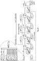
- FIGS 4 and 5 illustrate how different components may interact within the disclosed method.
- Figs. 4 and 5 may thus be combined freely, i.e. singly or in combination unless stated otherwise, with each other as well as those disclosed in relation to Figs. 1-3 above
- some aspects of the method comprises separating the assigned priorities into priorities for charging electric power units and priorities for discharging electric power units; for clarity, this is the case illustrated in Figs. 4 and 5 .
- separating the assigned priorities in this way, different priorities can be assigned depending on whether power flows in or out of the one or more energy sources.
- FIG. 4 illustrates power control of priorities for charging electric power units.
- electric power units of a mining machine interact with one or more energy sources of the mining machine, herein exemplified as a rechargeable battery, via a DC-bus.
- the DC-bus is configured to transmit and receive electric power to/from the rechargeable battery and the plurality of electric power units.
- the electric power is controlled by control circuitry for power control of the mining machine.
- the control circuitry is configured to assign S10 priorities to electric power units of the plurality of electric power units of the mining machine. Each electric power unit has an assigned priority.
- the control circuitry is further configured to control S20 electric power distribution for the plurality of electric power units based on the assigned priorities.
- the plurality of electric power units of the mining machine are here exemplified by a traction electric power unit, P traction , an auxiliary electric power unit, P auxiliary , a peripheral electric power unit, P peripheral , and a charger, brake chopper and (hydraulic) retarder electrical power unit, P ccr .
- the auxiliary electric power unit relates to the electric motor(s) driving the hydraulic system of the mining machine.
- a second engine such as a diesel engine, may be used as a charging electrical power unit.
- the peripheral electric power unit typically includes a 24 Volt system.
- the 24 Volt system is generally a low power system, but critical for control of the mining machine.
- a set of electric power units are grouped together in a functional unit and assigned a single priority for the functional unit.
- the charger, brake chopper and (hydraulic) retarder are physically different units, they represent a single functional unit, which may add or subtract power within limits given by P + ccr (see Fig. 4 ) and P - ccr (see Fig. 5 ).
- Charge power limits are denoted by a plus sign (see Fig. 4 ), since charge powers are defined as positive in this example, and discharge power limits are denoted by a minus sign (see Fig. 5 ) since discharge powers are defined as negative in this example.
- a virtual electric power unit, P corr is also introduced.
- the virtual electric power unit P corr is a correction term related to the difference between measured and requested battery power. In practice determination is more complicated than just determining said difference, e.g. because different units have different response times. In other words, the correction term may depend on the response times of the (other) electric power units.
- the correction term P corr is used to adjust power according to what is actually measured by the battery. In this example, a positive value indicates excessive DC-bus charge power. This will be subtracted from the amount of DC-bus charge power available to any other unit in the DC-bus. A negative value indicates excessive DC-bus discharge power. This will be subtracted from the amount of DC-bus discharge power available to any other unit in the DC-bus.
- the step of controlling S20 electric power distribution may comprise determining S22 power estimation errors for at least one of the plurality of electric power units based on electric power distribution feedback from the one or more energy sources.
- the step of controlling S20 electric power distribution may thus also comprise adjusting S24 a charging and/or a discharging power level of the at least one of the plurality of electric power units based on the determined power estimation errors.
- the control circuitry is preferably configured to obtain information about power usage for each electric power unit connected to the DC-bus.
- the control circuitry may also be configured to obtain information enabling the control circuitry to determine the amount of power the battery can currently handle. This enables the control circuitry to perform the task of controlling the allowed power out and into the electric power units in a prioritized order to stay within limits given by the battery.
- the control circuitry may optionally be configured to determine a battery energy level, such as state of charge, SoC. Completely draining or completely charging the battery would typically shorten the battery lifetime considerably. Therefore, only a part of the total energy of the battery is preferably used during operation of the mining machine.
- the maximum charge power levels and maximum discharge power levels are based on a desired state of charge, SoC, of the rechargeable battery. Likewise, charging and discharging the battery may cause temperature variations and/or temperature levels that can have a negative impact on the battery lifetime. Therefore, according to some aspects, the maximum charge power levels and maximum discharge power levels are based on a temperature of the rechargeable battery.
- the battery may continuously transmit charge and discharge power limits (of the battery) to the control circuitry based on the SoC and/or the temperature.
- Each battery will typically have a BMS configured to monitor a respective battery of a set of batteries, and set appropriate charge and discharge power limits for the batteries it is set to monitor.
- a battery management system, BMS is configured to monitor an operational status of the battery, e.g., a charge level or a temperature of the battery.
- the BMS may also be configured to control the operational status of a battery so that that the battery is protected from charging beyond a predetermined maximum charge level or depletion below a minimum charge level.
- each BMS is configured to provide the battery data to control circuitry of the mining machine configured to carry out the disclosed method.
- the amount of power to any electric power unit available to charge the DC-bus depends on the maximum available DC-bus charge power, P charge lim , indicating the DC-bus charge limit, and the demands of electric power units with higher priority.
- the step of controlling S20 electric power distribution is further based on a maximum charge power level ( Fig. 4 ) (and a maximum discharge power level - see Fig. 5 below) of the DC-bus of the mining machine.
- Electric power units adding power to the DC-bus will get their demands fulfilled in a prioritized order.
- the amount of power available to them here exemplified with a positive figure, may thus be determined based on a battery charge power limit and power demands of electric power units of the mining machine.
- a power charge margin, P m-charge is included as well.
- the maximum charge power level ( Fig. 4 ) and maximum discharge power level (see Fig. 5 for discharge) of an electrical power unit, further illustrated below, is based on a remaining DC-bus charge power and/or a remaining DC-bus discharge power, and further based on a predetermined power margin.
- the correction term P corr is used to adjust power according to what is actually measured by the battery by determining a power limit for traction, P + traction .
- a power limit, P + auxiliary is determined for the electric power unit having the next highest priority, here the auxiliary electric power unit, P auxiliary .
- P peripheral the peripheral electrical power unit, P peripheral .
- the step of controlling S20 electric power distribution is further based on measured power produced and consumed in each electric power unit. In practice though, since P peripheral is less than zero given the present convention, the control circuitry will only need to calculate P + traction and P + auxiliary (unless there are additional charging units of lower priority on the DC-bus). In other words, the step of controlling S20 electric power distribution is further based on respective maximum charge power levels ( Fig. 4 ) (and respective maximum discharge power levels-see Fig. 5 ) of the plurality of electric power units of the mining machine.
- An alternative or complementary aspect of controlling the power distribution comprises looking at a voltage level of the DC-bus. If the voltage level increases, the electric power increases as well. For instance, if an open circuit voltage, OCV, can be determined, and an inner resistance can be estimated, a change in the voltage level can be estimated based on a measured current. Thus, according to some aspects, the step of controlling S20 electric power distribution is further based on a voltage level of a DC-bus of the mining machine.
- Figure 5 which is to be read in concert with Fig. 4 above, illustrates power control of priorities for discharging electric power units.
- Figure 5 is largely a (discharge) mirror image of Fig. 4 , with the main difference being that the assigned priorities differ, as well as differences in (discharge) power limits for the electric power units.
- the (onboard) charger, brake chopper and retarder may be used to add or subtract power to the DC-bus. Consequently, the charger will not be simultaneously used with the brake chopper and/or retarder.
- the coordination of the charger, brake chopper and retarder into a single functional unit may be performed as follows. First, the margin to the battery charge limit is calculated for all units other than charger, brake chopper and retarder. Electric power less than the battery charge limit may be charged by the charger. Electric power exceeding the battery charge limit should be discharged by the use of the brake chopper and possibly the retarder. In case brake chopper discharge power is not enough, the retarder will be used.
- the resulting system illustrated in Figs. 4 and 5 can add an arbitrary number of chargers and/or dischargers. It should be noted that when the electric power is charged/discharged via the DC-bus, it is not only the charge/discharge capacity of the battery which determines how much an electrical power unit is allowed to receive; other electrical power units also influence the available power.
- the disclosed method has the advantage of avoiding assigning fixed power levels to each of the electric power units, which would not enable maximal utilization of the battery.
- the electric power control of the disclosed method can thus act both proactively by directly controlling the power, and reactively by estimating how much electric power is left to provide and provide feedback relating to the remaining available power to the control circuitry.
- the system implementing the disclosed method i.e. the disclosed control circuitry and the disclosed mining machine, may be configured to be able to operate with different priority configurations.
- An example of different priority configurations includes a high performance priority configuration.
- the high performance priority configuration may be configured to enable high peak electric power discharge from the battery at the expense of expected battery life time.
- Another example of different priority configurations includes a battery friendly priority configuration.
- the battery friendly priority configuration may be configured to weigh expected battery life time against electric power discharge need. For instance, the battery friendly priority configuration may be configured to maintain a state of charge of a battery within a desired predetermined range.
- the charge and discharge power limits of plurality of electric power units may be continuously updated. According to some aspects, the charge and discharge power limits are updated at a predetermined frequency. Likewise, the charge and discharge electric power limits of the DC-bus may be continuously updated, e.g. at a predetermined frequency. The electric power charge and discharge limits of the DC-bus as well as the individual electric power charge and discharge limits of the plurality of electric power units may be based on continuous updates, e.g. at a predetermined frequency, of the electric power charge and discharge demands of the plurality of electric power units. In other words, the electric power charge and discharge demands may be used in a feedback loop in order to continuously update the electric power charge and discharge limits of the DC-bus and/or the plurality of electric power units.
Landscapes
- Engineering & Computer Science (AREA)
- Power Engineering (AREA)
- Mining & Mineral Resources (AREA)
- Life Sciences & Earth Sciences (AREA)
- Mechanical Engineering (AREA)
- Geology (AREA)
- Geochemistry & Mineralogy (AREA)
- General Life Sciences & Earth Sciences (AREA)
- Transportation (AREA)
- Sustainable Development (AREA)
- Sustainable Energy (AREA)
- Charge And Discharge Circuits For Batteries Or The Like (AREA)
- Electric Propulsion And Braking For Vehicles (AREA)
- Control Of Multiple Motors (AREA)
Claims (15)
- Verfahren zur Leistungssteuerung einer Bergbaumaschine, umfassend:- Zuweisen (S10) von Prioritäten an elektrische Leistungseinheiten einer Vielzahl von elektrischen Leistungseinheiten der Bergbaumaschine, wobei jede elektrische Leistungseinheit eine zugewiesene Priorität aufweist; und- Steuern (S20) der Verteilung elektrischer Leistung für die Vielzahl von elektrischen Leistungseinheiten basierend auf den zugewiesenen Prioritäten;dadurch gekennzeichnet,dass die zugewiesenen Prioritäten in Prioritäten zum Laden der elektrischen Leistungseinheiten und Prioritäten zum Entladen der elektrischen Leistungseinheiten unterteilt sind; unddass der Schritt des Steuerns (S20) der Verteilung elektrischer Leistung ferner auf einem maximalen Ladeleistungspegel und einem maximalen Entladeleistungspegel einer Gleichstrom- (DC-) Sammelschiene der Bergbaumaschine basiert, wobei die DC-Sammelschiene so konfiguriert ist, dass sie elektrische Leistung an eine oder mehrere Energiequellen der Bergbaumaschine und die Vielzahl der elektrischen Leistungseinheiten überträgt und von diesen empfängt.
- Verfahren nach Anspruch 1, wobei eine oder mehrere Energiequellen der Bergbaumaschine mindestens eines der Folgenden umfassen: wiederaufladbare Batterie, Superkondensator, wiederaufladbare Brennstoffzelle und Schwungrad.
- Verfahren nach einem der vorhergehenden Ansprüche, wobei der Schritt des Steuerns (S20) der Verteilung elektrischer Leistung ferner auf den jeweiligen maximalen Ladeleistungspegeln und den jeweiligen maximalen Entladeleistungspegeln der Vielzahl von elektrischen Leistungseinheiten der Bergbaumaschine basiert.
- Verfahren nach einem der vorhergehenden Ansprüche, wobei der maximale Ladeleistungspegel und der maximale Entladeleistungpegel einer elektrischen Leistungseinheit auf einer verbleibenden Ladeleistung der DC-Sammelschiene und/oder einer verbleibenden Entladeleistung der DC-Sammelschiene und ferner auf einer vorbestimmten Leistungsgrenze basiert.
- Verfahren nach einem der vorhergehenden Ansprüche, wobei der Schritt des Steuerns (S20) der Verteilung elektrischer Leistung ferner auf einem Spannungspegel einer Gleichstrom- (DC-) Sammelschiene der Bergbaumaschine basiert,
wobei die DC-Sammelschiene so konfiguriert ist, dass sie elektrische Leistung an mindestens eines von wiederaufladbarer Batterie, Superkondensator, wiederaufladbarer Brennstoffzelle und Schwungrad der Bergbaumaschine und die Vielzahl von elektrischen Leistungseinheiten überträgt und von diesen empfängt. - Verfahren nach einem der vorhergehenden Ansprüche, wobei eine Gruppe von elektrischen Leistungseinheiten zu einer Funktionseinheit zusammengefasst und der Funktionseinheit eine einzige Priorität zugewiesen wird.
- Verfahren nach Anspruch 6, wobei die Funktionseinheit von elektrischen Leistungseinheiten ein Ladegerät, einen Brems-Chopper und einen Verzögerer umfasst.
- Verfahren nach einem der vorhergehenden Ansprüche, wobei der Schritt des Steuerns (S20) der Verteilung der elektrischen Leistung ferner auf der gemessenen Leistung basiert, die in jeder elektrischen Leistungseinheit produziert und verbraucht wird.
- Verfahren nach einem der vorhergehenden Ansprüche, wobei der Schritt des Steuerns (S20) der Verteilung elektrischer Leistung ferner Folgendes umfasst:- Bestimmen (S22) von Leistungsschätzungsfehlern für mindestens eine der Vielzahl von elektrischen Leistungseinheiten basierend auf der Rückkopplung der Verteilung elektrischer Leistung von einer oder mehreren Energiequellen der Bergbaumaschine, und- Anpassen (S24) eines Lade- und/oder Entladeleistungspegels der mindestens einen der Vielzahl von elektrischen Leistungseinheiten basierend auf den bestimmen Leistungsschätzungsfehlern.
- Verfahren nach einem der vorhergehenden Ansprüche, wobei die elektrischen Leistungslade- und -entladeforderungen der Vielzahl von elektrischen Leistungseinheiten in einer Rückkopplungsschleife verwendet werden, um die elektrischen Leistungslade- und- entladegrenzen einer Gleichstrom- (DC-) Sammelschiene der Bergbaumschine und/oder der Vielzahl von elektrischen Leistungseinheiten kontinuierlich zu aktualisieren.
- Computerprogramm zur Leistungssteuerung einer Bergbaumaschine, wobei das Computerprogramm einen Computerprogrammcode umfasst, der bei Ausführung bewirkt, dass die Steuerschaltung einer Bergbaumaschine das Verfahren nach einem der Ansprüche 1 bis 10 ausführt.
- Steuerschaltung (240, 340) zur Leistungssteuerung einer Bergbaumaschine, wobei die Steuerschaltung konfiguriert ist zum- Zuweisen von Prioritäten an elektrische Leistungseinheiten einer Vielzahl von elektrischen Leistungseinheiten der Bergbaumaschine, wobei jede elektrische Leistungseinheit eine zugewiesene Priorität aufweist; und- Steuern der Verteilung elektrischer Leistung für die Vielzahl von elektrischen Leistungseinheiten basierend auf den zugewiesenen Prioritäten;dadurch gekennzeichnet,dass die zugewiesenen Prioritäten in Prioritäten zum Laden der elektrischen Leistungseinheiten und Prioritäten zum Entladen der elektrischen Leistungseinheiten unterteilt sind, unddass das Steuern der Verteilung elektrischer Leistung ferner auf einem maximalen Ladeleistungspegel und einem maximalen Entladeleistungspegel einer Gleichstrom- (DC-) Sammelschiene der Bergbaumaschine basiert, wobei die DC-Sammelschiene so konfiguriert ist, dass sie elektrische Leistung an eine oder mehrere Energiequellen der Bergbaumaschine und die Vielzahl der elektrischen Leistungseinheiten überträgt und von diesen empfängt.
- Steuerschaltung (240, 340) nach Anspruch 12, ferner umfassend einen Prozessor (242, 342) und einen Speicher (244, 344), wobei in dem Speicher ein Computerprogramm nach Anspruch 11 gespeichert ist, und wobei der Prozessor dazu konfiguriert ist, das Computerprogramm auszuführen.
- Bergbaumaschine (300), umfassend:- eine oder mehrere Energiequellen (310),- eine Vielzahl von elektrischen Leistungseinheiten (320a, 320b, 320c), und- eine Steuerschaltung (340) nach Anspruch 12, wobei die Bergbaumaschine so konfiguriert ist, dass sie elektrische Leistung an die eine oder die mehreren Energiequellen und die Vielzahl von elektrischen Leistungseinheiten überträgt und von diesen empfängt.
- Bergbaumaschine nach Anspruch 14, ferner umfassend eine Maschinensteuereinheit (350), die so konfiguriert ist, dass sie ein oder mehrere elektrische Systeme und/oder Teilsysteme der Bergbaumaschine, einschließlich der Steuerschaltung (340), steuert.
Applications Claiming Priority (2)
| Application Number | Priority Date | Filing Date | Title |
|---|---|---|---|
| SE1850848A SE543007C2 (en) | 2018-07-04 | 2018-07-04 | Methods and devices for power control in mining machines |
| PCT/SE2019/050653 WO2020009646A1 (en) | 2018-07-04 | 2019-07-02 | Methods and devices for power control in mining machines |
Publications (3)
| Publication Number | Publication Date |
|---|---|
| EP3818249A1 EP3818249A1 (de) | 2021-05-12 |
| EP3818249B1 true EP3818249B1 (de) | 2022-04-06 |
| EP3818249B2 EP3818249B2 (de) | 2026-03-04 |
Family
ID=67185690
Family Applications (1)
| Application Number | Title | Priority Date | Filing Date |
|---|---|---|---|
| EP19736839.2A Active EP3818249B2 (de) | 2018-07-04 | 2019-07-02 | Verfahren und vorrichtungen zur leistungssteuerung in bergbaumaschinen |
Country Status (8)
| Country | Link |
|---|---|
| EP (1) | EP3818249B2 (de) |
| CN (1) | CN112272732B (de) |
| AU (1) | AU2019299827B2 (de) |
| CA (1) | CA3103210A1 (de) |
| FI (1) | FI3818249T4 (de) |
| SE (1) | SE543007C2 (de) |
| WO (1) | WO2020009646A1 (de) |
| ZA (1) | ZA202006451B (de) |
Cited By (1)
| Publication number | Priority date | Publication date | Assignee | Title |
|---|---|---|---|---|
| WO2025234905A1 (en) * | 2024-05-08 | 2025-11-13 | Epiroc Rock Drills Aktiebolag | Method and arrangement in a battery-powered rock drilling rig |
Families Citing this family (1)
| Publication number | Priority date | Publication date | Assignee | Title |
|---|---|---|---|---|
| EP4090547A1 (de) * | 2020-01-15 | 2022-11-23 | Epiroc Rock Drills Aktiebolag | Verfahren und anordnung für eine batteriebetriebene bergbaumaschine |
Citations (11)
| Publication number | Priority date | Publication date | Assignee | Title |
|---|---|---|---|---|
| EP1455439A1 (de) | 2001-11-21 | 2004-09-08 | Kobelco Construction Machinery Co., Ltd. | Stellgliedansteuereinrichtung einer arbeitsmaschine |
| EP1241041B1 (de) | 2001-03-14 | 2004-10-20 | Conception et Développement Michelin S.A. | Fahrzeug mit Super-Kondensator zur Bremsenergie-Rückgewinnung |
| JP2007191973A (ja) | 2006-01-20 | 2007-08-02 | Shin Caterpillar Mitsubishi Ltd | ハイブリッド用動力制御システム |
| EP2243676A1 (de) | 2009-04-20 | 2010-10-27 | Sumitomo Heavy Industries, LTD. | Arbeitsmaschine des Hybridtyps |
| WO2011109050A2 (en) | 2010-03-04 | 2011-09-09 | General Electric Company | Electric drive vehicle, system and method |
| WO2011148051A1 (en) | 2010-05-25 | 2011-12-01 | Sandvik Mining And Construction Oy | Rock drilling rig and method for downhill drive |
| EP2562030A2 (de) | 2011-08-24 | 2013-02-27 | General Electric Company | Vorrichtung und Verfahren zum Aufladen eines elektrischen Fahrzeugs |
| JP5340627B2 (ja) | 2008-04-15 | 2013-11-13 | 住友重機械工業株式会社 | ハイブリッド式建設機械 |
| EP2684732A1 (de) | 2012-07-09 | 2014-01-15 | ABB Oy | Elektrisches System mit einem Gleichstromzwischenkreis |
| WO2014073106A1 (ja) | 2012-11-12 | 2014-05-15 | ボルボ ラストバグナー アクチエボラグ | 充放電システム |
| WO2016191686A1 (en) | 2015-05-28 | 2016-12-01 | Joy Global Longview Operations Llc | Mining machine and energy storage system for same |
Family Cites Families (7)
| Publication number | Priority date | Publication date | Assignee | Title |
|---|---|---|---|---|
| US8212532B2 (en) * | 2008-07-24 | 2012-07-03 | General Electric Company | Method and system for control of a vehicle energy storage device |
| US8698437B2 (en) * | 2009-05-15 | 2014-04-15 | Siemens Industry, Inc. | System and method for providing auxiliary power by regeneration power management in mobile mining equipment |
| JP6084766B2 (ja) * | 2011-05-10 | 2017-02-22 | 株式会社小松製作所 | 鉱山用電力管理システム |
| CN105324907B (zh) * | 2013-06-20 | 2018-12-21 | 沃尔沃卡车集团 | 用于控制能量存储系统的方法 |
| US9722442B2 (en) * | 2014-10-28 | 2017-08-01 | General Electric Company | System and method for transferring energy between vehicles |
| US9550434B2 (en) * | 2014-12-31 | 2017-01-24 | General Electric Company | Energy management system and method for a vehicle |
| SE541333C2 (en) * | 2017-11-06 | 2019-07-09 | Epiroc Rock Drills Ab | Power system in a mining machine |
-
2018
- 2018-07-04 SE SE1850848A patent/SE543007C2/en unknown
-
2019
- 2019-07-02 CN CN201980038966.5A patent/CN112272732B/zh active Active
- 2019-07-02 AU AU2019299827A patent/AU2019299827B2/en active Active
- 2019-07-02 EP EP19736839.2A patent/EP3818249B2/de active Active
- 2019-07-02 FI FIEP19736839.2T patent/FI3818249T4/sv active
- 2019-07-02 WO PCT/SE2019/050653 patent/WO2020009646A1/en not_active Ceased
- 2019-07-02 CA CA3103210A patent/CA3103210A1/en active Pending
-
2020
- 2020-10-16 ZA ZA2020/06451A patent/ZA202006451B/en unknown
Patent Citations (12)
| Publication number | Priority date | Publication date | Assignee | Title |
|---|---|---|---|---|
| EP1241041B1 (de) | 2001-03-14 | 2004-10-20 | Conception et Développement Michelin S.A. | Fahrzeug mit Super-Kondensator zur Bremsenergie-Rückgewinnung |
| EP1455439A1 (de) | 2001-11-21 | 2004-09-08 | Kobelco Construction Machinery Co., Ltd. | Stellgliedansteuereinrichtung einer arbeitsmaschine |
| JP2007191973A (ja) | 2006-01-20 | 2007-08-02 | Shin Caterpillar Mitsubishi Ltd | ハイブリッド用動力制御システム |
| JP5340627B2 (ja) | 2008-04-15 | 2013-11-13 | 住友重機械工業株式会社 | ハイブリッド式建設機械 |
| EP2243676A1 (de) | 2009-04-20 | 2010-10-27 | Sumitomo Heavy Industries, LTD. | Arbeitsmaschine des Hybridtyps |
| WO2011109050A2 (en) | 2010-03-04 | 2011-09-09 | General Electric Company | Electric drive vehicle, system and method |
| WO2011148051A1 (en) | 2010-05-25 | 2011-12-01 | Sandvik Mining And Construction Oy | Rock drilling rig and method for downhill drive |
| EP2562030A2 (de) | 2011-08-24 | 2013-02-27 | General Electric Company | Vorrichtung und Verfahren zum Aufladen eines elektrischen Fahrzeugs |
| EP2684732A1 (de) | 2012-07-09 | 2014-01-15 | ABB Oy | Elektrisches System mit einem Gleichstromzwischenkreis |
| WO2014073106A1 (ja) | 2012-11-12 | 2014-05-15 | ボルボ ラストバグナー アクチエボラグ | 充放電システム |
| EP2918442B1 (de) | 2012-11-12 | 2021-06-23 | Volvo Truck Corporation | Lade-/entladesystem |
| WO2016191686A1 (en) | 2015-05-28 | 2016-12-01 | Joy Global Longview Operations Llc | Mining machine and energy storage system for same |
Cited By (1)
| Publication number | Priority date | Publication date | Assignee | Title |
|---|---|---|---|---|
| WO2025234905A1 (en) * | 2024-05-08 | 2025-11-13 | Epiroc Rock Drills Aktiebolag | Method and arrangement in a battery-powered rock drilling rig |
Also Published As
| Publication number | Publication date |
|---|---|
| SE543007C2 (en) | 2020-09-22 |
| CA3103210A1 (en) | 2020-01-09 |
| CN112272732B (zh) | 2023-07-28 |
| ZA202006451B (en) | 2023-03-29 |
| WO2020009646A1 (en) | 2020-01-09 |
| AU2019299827B2 (en) | 2025-01-30 |
| EP3818249B2 (de) | 2026-03-04 |
| EP3818249A1 (de) | 2021-05-12 |
| FI3818249T4 (sv) | 2026-04-10 |
| SE1850848A1 (en) | 2020-01-05 |
| CN112272732A (zh) | 2021-01-26 |
| AU2019299827A1 (en) | 2020-12-10 |
Similar Documents
| Publication | Publication Date | Title |
|---|---|---|
| JP4306746B2 (ja) | 車両用電源装置 | |
| CN101595620B (zh) | 电源系统及电源系统的电力供应控制方法 | |
| US11411418B2 (en) | Battery management systems and methods | |
| US11404885B1 (en) | Large-format battery management systems with gateway PCBA | |
| US11411407B1 (en) | Large-format battery management systems with gateway PCBA | |
| US10740991B2 (en) | Method and device for controlling an electric or a hybrid electric vehicle | |
| EP3832837A1 (de) | Ladesystem für industriefahrzeug | |
| CN112384405B (zh) | 控制车辆中的电池系统的方法 | |
| CN104115366B (zh) | 挖土机及挖土机的控制方法 | |
| KR101702379B1 (ko) | 모듈형 능동 셀밸런싱 장치, 모듈형 배터리 블록, 배터리 팩, 및 에너지 저장 시스템 | |
| JP2016208832A (ja) | バッテリ制御装置、バッテリモジュール、バッテリパック、及びバッテリ制御方法 | |
| WO2020009645A1 (en) | Battery charge management of mining machines | |
| EP3818249B1 (de) | Verfahren und vorrichtungen zur leistungssteuerung in bergbaumaschinen | |
| CN109120059A (zh) | 用于控制不间断电源系统的方法以及相关联的电源系统 | |
| US20250206173A1 (en) | Control device and method for controlling charging of an energy storage device | |
| JP6394817B2 (ja) | 電源システムおよび該システムにおけるパワーアシスト開始点の再設定方法 | |
| WO2023044190A1 (en) | Large-format battery management systems with gateway pcba | |
| JP2021164223A (ja) | 電力制御装置及び電力制御方法 | |
| JP2016111735A (ja) | 電力制御システムおよび電力制御方法 | |
| JP7743597B1 (ja) | 充電システム | |
| JPH10262342A (ja) | 充電装置 | |
| WO2025070579A1 (ja) | 作業機械及び作業機械の制御方法 | |
| KR20130133608A (ko) | 로봇용 배터리관리시스템 | |
| KR20220128727A (ko) | 재사용 리튬이온 배터리 모듈을 이용한 무정전 전원 공급 장치 | |
| JP2020191746A (ja) | 蓄電デバイスを充電する方法及びシステム |
Legal Events
| Date | Code | Title | Description |
|---|---|---|---|
| STAA | Information on the status of an ep patent application or granted ep patent |
Free format text: STATUS: UNKNOWN |
|
| STAA | Information on the status of an ep patent application or granted ep patent |
Free format text: STATUS: THE INTERNATIONAL PUBLICATION HAS BEEN MADE |
|
| PUAI | Public reference made under article 153(3) epc to a published international application that has entered the european phase |
Free format text: ORIGINAL CODE: 0009012 |
|
| STAA | Information on the status of an ep patent application or granted ep patent |
Free format text: STATUS: REQUEST FOR EXAMINATION WAS MADE |
|
| 17P | Request for examination filed |
Effective date: 20201023 |
|
| AK | Designated contracting states |
Kind code of ref document: A1 Designated state(s): AL AT BE BG CH CY CZ DE DK EE ES FI FR GB GR HR HU IE IS IT LI LT LU LV MC MK MT NL NO PL PT RO RS SE SI SK SM TR |
|
| DAV | Request for validation of the european patent (deleted) | ||
| DAX | Request for extension of the european patent (deleted) | ||
| GRAP | Despatch of communication of intention to grant a patent |
Free format text: ORIGINAL CODE: EPIDOSNIGR1 |
|
| STAA | Information on the status of an ep patent application or granted ep patent |
Free format text: STATUS: GRANT OF PATENT IS INTENDED |
|
| INTG | Intention to grant announced |
Effective date: 20211123 |
|
| GRAS | Grant fee paid |
Free format text: ORIGINAL CODE: EPIDOSNIGR3 |
|
| GRAA | (expected) grant |
Free format text: ORIGINAL CODE: 0009210 |
|
| STAA | Information on the status of an ep patent application or granted ep patent |
Free format text: STATUS: THE PATENT HAS BEEN GRANTED |
|
| AK | Designated contracting states |
Kind code of ref document: B1 Designated state(s): AL AT BE BG CH CY CZ DE DK EE ES FI FR GB GR HR HU IE IS IT LI LT LU LV MC MK MT NL NO PL PT RO RS SE SI SK SM TR |
|
| REG | Reference to a national code |
Ref country code: GB Ref legal event code: FG4D |
|
| REG | Reference to a national code |
Ref country code: CH Ref legal event code: EP |
|
| REG | Reference to a national code |
Ref country code: AT Ref legal event code: REF Ref document number: 1481519 Country of ref document: AT Kind code of ref document: T Effective date: 20220415 |
|
| REG | Reference to a national code |
Ref country code: IE Ref legal event code: FG4D |
|
| REG | Reference to a national code |
Ref country code: DE Ref legal event code: R096 Ref document number: 602019013495 Country of ref document: DE |
|
| REG | Reference to a national code |
Ref country code: FI Ref legal event code: FGE |
|
| REG | Reference to a national code |
Ref country code: SE Ref legal event code: TRGR |
|
| REG | Reference to a national code |
Ref country code: LT Ref legal event code: MG9D |
|
| REG | Reference to a national code |
Ref country code: NL Ref legal event code: MP Effective date: 20220406 |
|
| REG | Reference to a national code |
Ref country code: AT Ref legal event code: MK05 Ref document number: 1481519 Country of ref document: AT Kind code of ref document: T Effective date: 20220406 |
|
| PG25 | Lapsed in a contracting state [announced via postgrant information from national office to epo] |
Ref country code: NL Free format text: LAPSE BECAUSE OF FAILURE TO SUBMIT A TRANSLATION OF THE DESCRIPTION OR TO PAY THE FEE WITHIN THE PRESCRIBED TIME-LIMIT Effective date: 20220406 |
|
| PG25 | Lapsed in a contracting state [announced via postgrant information from national office to epo] |
Ref country code: PT Free format text: LAPSE BECAUSE OF FAILURE TO SUBMIT A TRANSLATION OF THE DESCRIPTION OR TO PAY THE FEE WITHIN THE PRESCRIBED TIME-LIMIT Effective date: 20220808 Ref country code: NO Free format text: LAPSE BECAUSE OF FAILURE TO SUBMIT A TRANSLATION OF THE DESCRIPTION OR TO PAY THE FEE WITHIN THE PRESCRIBED TIME-LIMIT Effective date: 20220706 Ref country code: LT Free format text: LAPSE BECAUSE OF FAILURE TO SUBMIT A TRANSLATION OF THE DESCRIPTION OR TO PAY THE FEE WITHIN THE PRESCRIBED TIME-LIMIT Effective date: 20220406 Ref country code: HR Free format text: LAPSE BECAUSE OF FAILURE TO SUBMIT A TRANSLATION OF THE DESCRIPTION OR TO PAY THE FEE WITHIN THE PRESCRIBED TIME-LIMIT Effective date: 20220406 Ref country code: GR Free format text: LAPSE BECAUSE OF FAILURE TO SUBMIT A TRANSLATION OF THE DESCRIPTION OR TO PAY THE FEE WITHIN THE PRESCRIBED TIME-LIMIT Effective date: 20220707 Ref country code: ES Free format text: LAPSE BECAUSE OF FAILURE TO SUBMIT A TRANSLATION OF THE DESCRIPTION OR TO PAY THE FEE WITHIN THE PRESCRIBED TIME-LIMIT Effective date: 20220406 Ref country code: BG Free format text: LAPSE BECAUSE OF FAILURE TO SUBMIT A TRANSLATION OF THE DESCRIPTION OR TO PAY THE FEE WITHIN THE PRESCRIBED TIME-LIMIT Effective date: 20220706 Ref country code: AT Free format text: LAPSE BECAUSE OF FAILURE TO SUBMIT A TRANSLATION OF THE DESCRIPTION OR TO PAY THE FEE WITHIN THE PRESCRIBED TIME-LIMIT Effective date: 20220406 |
|
| PG25 | Lapsed in a contracting state [announced via postgrant information from national office to epo] |
Ref country code: RS Free format text: LAPSE BECAUSE OF FAILURE TO SUBMIT A TRANSLATION OF THE DESCRIPTION OR TO PAY THE FEE WITHIN THE PRESCRIBED TIME-LIMIT Effective date: 20220406 Ref country code: PL Free format text: LAPSE BECAUSE OF FAILURE TO SUBMIT A TRANSLATION OF THE DESCRIPTION OR TO PAY THE FEE WITHIN THE PRESCRIBED TIME-LIMIT Effective date: 20220406 Ref country code: LV Free format text: LAPSE BECAUSE OF FAILURE TO SUBMIT A TRANSLATION OF THE DESCRIPTION OR TO PAY THE FEE WITHIN THE PRESCRIBED TIME-LIMIT Effective date: 20220406 Ref country code: IS Free format text: LAPSE BECAUSE OF FAILURE TO SUBMIT A TRANSLATION OF THE DESCRIPTION OR TO PAY THE FEE WITHIN THE PRESCRIBED TIME-LIMIT Effective date: 20220806 |
|
| REG | Reference to a national code |
Ref country code: DE Ref legal event code: R026 Ref document number: 602019013495 Country of ref document: DE |
|
| PLBI | Opposition filed |
Free format text: ORIGINAL CODE: 0009260 |
|
| PLAX | Notice of opposition and request to file observation + time limit sent |
Free format text: ORIGINAL CODE: EPIDOSNOBS2 |
|
| PG25 | Lapsed in a contracting state [announced via postgrant information from national office to epo] |
Ref country code: SM Free format text: LAPSE BECAUSE OF FAILURE TO SUBMIT A TRANSLATION OF THE DESCRIPTION OR TO PAY THE FEE WITHIN THE PRESCRIBED TIME-LIMIT Effective date: 20220406 Ref country code: SK Free format text: LAPSE BECAUSE OF FAILURE TO SUBMIT A TRANSLATION OF THE DESCRIPTION OR TO PAY THE FEE WITHIN THE PRESCRIBED TIME-LIMIT Effective date: 20220406 Ref country code: RO Free format text: LAPSE BECAUSE OF FAILURE TO SUBMIT A TRANSLATION OF THE DESCRIPTION OR TO PAY THE FEE WITHIN THE PRESCRIBED TIME-LIMIT Effective date: 20220406 Ref country code: EE Free format text: LAPSE BECAUSE OF FAILURE TO SUBMIT A TRANSLATION OF THE DESCRIPTION OR TO PAY THE FEE WITHIN THE PRESCRIBED TIME-LIMIT Effective date: 20220406 Ref country code: DK Free format text: LAPSE BECAUSE OF FAILURE TO SUBMIT A TRANSLATION OF THE DESCRIPTION OR TO PAY THE FEE WITHIN THE PRESCRIBED TIME-LIMIT Effective date: 20220406 Ref country code: CZ Free format text: LAPSE BECAUSE OF FAILURE TO SUBMIT A TRANSLATION OF THE DESCRIPTION OR TO PAY THE FEE WITHIN THE PRESCRIBED TIME-LIMIT Effective date: 20220406 |
|
| REG | Reference to a national code |
Ref country code: DE Ref legal event code: R119 Ref document number: 602019013495 Country of ref document: DE |
|
| 26 | Opposition filed |
Opponent name: SANDVIK MINING AND CONSTRUCTION OY AB Effective date: 20230105 |
|
| PG25 | Lapsed in a contracting state [announced via postgrant information from national office to epo] |
Ref country code: MC Free format text: LAPSE BECAUSE OF FAILURE TO SUBMIT A TRANSLATION OF THE DESCRIPTION OR TO PAY THE FEE WITHIN THE PRESCRIBED TIME-LIMIT Effective date: 20220406 |
|
| REG | Reference to a national code |
Ref country code: CH Ref legal event code: PL |
|
| REG | Reference to a national code |
Ref country code: BE Ref legal event code: MM Effective date: 20220731 |
|
| PG25 | Lapsed in a contracting state [announced via postgrant information from national office to epo] |
Ref country code: AL Free format text: LAPSE BECAUSE OF FAILURE TO SUBMIT A TRANSLATION OF THE DESCRIPTION OR TO PAY THE FEE WITHIN THE PRESCRIBED TIME-LIMIT Effective date: 20220406 |
|
| PG25 | Lapsed in a contracting state [announced via postgrant information from national office to epo] |
Ref country code: LU Free format text: LAPSE BECAUSE OF NON-PAYMENT OF DUE FEES Effective date: 20220702 Ref country code: LI Free format text: LAPSE BECAUSE OF NON-PAYMENT OF DUE FEES Effective date: 20220731 Ref country code: FR Free format text: LAPSE BECAUSE OF NON-PAYMENT OF DUE FEES Effective date: 20220731 Ref country code: CH Free format text: LAPSE BECAUSE OF NON-PAYMENT OF DUE FEES Effective date: 20220731 |
|
| PLBB | Reply of patent proprietor to notice(s) of opposition received |
Free format text: ORIGINAL CODE: EPIDOSNOBS3 |
|
| PG25 | Lapsed in a contracting state [announced via postgrant information from national office to epo] |
Ref country code: SI Free format text: LAPSE BECAUSE OF FAILURE TO SUBMIT A TRANSLATION OF THE DESCRIPTION OR TO PAY THE FEE WITHIN THE PRESCRIBED TIME-LIMIT Effective date: 20220406 Ref country code: DE Free format text: LAPSE BECAUSE OF NON-PAYMENT OF DUE FEES Effective date: 20230201 Ref country code: BE Free format text: LAPSE BECAUSE OF NON-PAYMENT OF DUE FEES Effective date: 20220731 |
|
| PG25 | Lapsed in a contracting state [announced via postgrant information from national office to epo] |
Ref country code: IE Free format text: LAPSE BECAUSE OF NON-PAYMENT OF DUE FEES Effective date: 20220702 |
|
| PG25 | Lapsed in a contracting state [announced via postgrant information from national office to epo] |
Ref country code: IT Free format text: LAPSE BECAUSE OF FAILURE TO SUBMIT A TRANSLATION OF THE DESCRIPTION OR TO PAY THE FEE WITHIN THE PRESCRIBED TIME-LIMIT Effective date: 20220406 |
|
| GBPC | Gb: european patent ceased through non-payment of renewal fee |
Effective date: 20230702 |
|
| PG25 | Lapsed in a contracting state [announced via postgrant information from national office to epo] |
Ref country code: MK Free format text: LAPSE BECAUSE OF FAILURE TO SUBMIT A TRANSLATION OF THE DESCRIPTION OR TO PAY THE FEE WITHIN THE PRESCRIBED TIME-LIMIT Effective date: 20220406 Ref country code: CY Free format text: LAPSE BECAUSE OF FAILURE TO SUBMIT A TRANSLATION OF THE DESCRIPTION OR TO PAY THE FEE WITHIN THE PRESCRIBED TIME-LIMIT Effective date: 20220406 Ref country code: GB Free format text: LAPSE BECAUSE OF NON-PAYMENT OF DUE FEES Effective date: 20230702 |
|
| APAH | Appeal reference modified |
Free format text: ORIGINAL CODE: EPIDOSCREFNO |
|
| APBP | Date of receipt of notice of appeal recorded |
Free format text: ORIGINAL CODE: EPIDOSNNOA2O |
|
| PG25 | Lapsed in a contracting state [announced via postgrant information from national office to epo] |
Ref country code: HU Free format text: LAPSE BECAUSE OF FAILURE TO SUBMIT A TRANSLATION OF THE DESCRIPTION OR TO PAY THE FEE WITHIN THE PRESCRIBED TIME-LIMIT; INVALID AB INITIO Effective date: 20190702 |
|
| APAH | Appeal reference modified |
Free format text: ORIGINAL CODE: EPIDOSCREFNO |
|
| APBQ | Date of receipt of statement of grounds of appeal recorded |
Free format text: ORIGINAL CODE: EPIDOSNNOA3O |
|
| PG25 | Lapsed in a contracting state [announced via postgrant information from national office to epo] |
Ref country code: MT Free format text: LAPSE BECAUSE OF FAILURE TO SUBMIT A TRANSLATION OF THE DESCRIPTION OR TO PAY THE FEE WITHIN THE PRESCRIBED TIME-LIMIT Effective date: 20220406 |
|
| PG25 | Lapsed in a contracting state [announced via postgrant information from national office to epo] |
Ref country code: BG Free format text: LAPSE BECAUSE OF FAILURE TO SUBMIT A TRANSLATION OF THE DESCRIPTION OR TO PAY THE FEE WITHIN THE PRESCRIBED TIME-LIMIT Effective date: 20220406 |
|
| PG25 | Lapsed in a contracting state [announced via postgrant information from national office to epo] |
Ref country code: BG Free format text: LAPSE BECAUSE OF FAILURE TO SUBMIT A TRANSLATION OF THE DESCRIPTION OR TO PAY THE FEE WITHIN THE PRESCRIBED TIME-LIMIT Effective date: 20220406 |
|
| PGFP | Annual fee paid to national office [announced via postgrant information from national office to epo] |
Ref country code: FI Payment date: 20250620 Year of fee payment: 7 |
|
| PGFP | Annual fee paid to national office [announced via postgrant information from national office to epo] |
Ref country code: SE Payment date: 20250619 Year of fee payment: 7 |
|
| APBU | Appeal procedure closed |
Free format text: ORIGINAL CODE: EPIDOSNNOA9O |
|
| PG25 | Lapsed in a contracting state [announced via postgrant information from national office to epo] |
Ref country code: TR Free format text: LAPSE BECAUSE OF FAILURE TO SUBMIT A TRANSLATION OF THE DESCRIPTION OR TO PAY THE FEE WITHIN THE PRESCRIBED TIME-LIMIT Effective date: 20220406 |
|
| PUAH | Patent maintained in amended form |
Free format text: ORIGINAL CODE: 0009272 |
|
| STAA | Information on the status of an ep patent application or granted ep patent |
Free format text: STATUS: PATENT MAINTAINED AS AMENDED |
|
| REG | Reference to a national code |
Ref country code: CH Ref legal event code: M12 Free format text: ST27 STATUS EVENT CODE: U-0-0-M10-M12 (AS PROVIDED BY THE NATIONAL OFFICE) Effective date: 20260204 |
|
| 27A | Patent maintained in amended form |
Effective date: 20260304 |
|
| AK | Designated contracting states |
Kind code of ref document: B2 Designated state(s): AL AT BE BG CH CY CZ DE DK EE ES FI FR GB GR HR HU IE IS IT LI LT LU LV MC MK MT NL NO PL PT RO RS SE SI SK SM TR |
|
| REG | Reference to a national code |
Ref country code: DE Ref legal event code: R102 Ref document number: 602019013495 Country of ref document: DE |