EP3818923B1 - Selbstadaptives optisches retinabildgebungssystem mit grossem sichtfeld und verfahren mit common-path-lichtstrahlabtastung - Google Patents
Selbstadaptives optisches retinabildgebungssystem mit grossem sichtfeld und verfahren mit common-path-lichtstrahlabtastung Download PDFInfo
- Publication number
- EP3818923B1 EP3818923B1 EP19917523.3A EP19917523A EP3818923B1 EP 3818923 B1 EP3818923 B1 EP 3818923B1 EP 19917523 A EP19917523 A EP 19917523A EP 3818923 B1 EP3818923 B1 EP 3818923B1
- Authority
- EP
- European Patent Office
- Prior art keywords
- module
- scanning
- imaging
- view
- light
- Prior art date
- Legal status (The legal status is an assumption and is not a legal conclusion. Google has not performed a legal analysis and makes no representation as to the accuracy of the status listed.)
- Active
Links
Images
Classifications
-
- A—HUMAN NECESSITIES
- A61—MEDICAL OR VETERINARY SCIENCE; HYGIENE
- A61B—DIAGNOSIS; SURGERY; IDENTIFICATION
- A61B3/00—Apparatus for testing the eyes; Instruments for examining the eyes
- A61B3/10—Objective types, i.e. instruments for examining the eyes independent of the patients' perceptions or reactions
- A61B3/12—Objective types, i.e. instruments for examining the eyes independent of the patients' perceptions or reactions for looking at the eye fundus, e.g. ophthalmoscopes
-
- A—HUMAN NECESSITIES
- A61—MEDICAL OR VETERINARY SCIENCE; HYGIENE
- A61B—DIAGNOSIS; SURGERY; IDENTIFICATION
- A61B3/00—Apparatus for testing the eyes; Instruments for examining the eyes
- A61B3/10—Objective types, i.e. instruments for examining the eyes independent of the patients' perceptions or reactions
- A61B3/14—Arrangements specially adapted for eye photography
- A61B3/15—Arrangements specially adapted for eye photography with means for aligning, spacing or blocking spurious reflection ; with means for relaxing
- A61B3/152—Arrangements specially adapted for eye photography with means for aligning, spacing or blocking spurious reflection ; with means for relaxing for aligning
-
- A—HUMAN NECESSITIES
- A61—MEDICAL OR VETERINARY SCIENCE; HYGIENE
- A61B—DIAGNOSIS; SURGERY; IDENTIFICATION
- A61B3/00—Apparatus for testing the eyes; Instruments for examining the eyes
- A61B3/0008—Apparatus for testing the eyes; Instruments for examining the eyes provided with illuminating means
-
- A—HUMAN NECESSITIES
- A61—MEDICAL OR VETERINARY SCIENCE; HYGIENE
- A61B—DIAGNOSIS; SURGERY; IDENTIFICATION
- A61B3/00—Apparatus for testing the eyes; Instruments for examining the eyes
- A61B3/0016—Operational features thereof
- A61B3/0025—Operational features thereof characterised by electronic signal processing, e.g. eye models
-
- A—HUMAN NECESSITIES
- A61—MEDICAL OR VETERINARY SCIENCE; HYGIENE
- A61B—DIAGNOSIS; SURGERY; IDENTIFICATION
- A61B3/00—Apparatus for testing the eyes; Instruments for examining the eyes
- A61B3/10—Objective types, i.e. instruments for examining the eyes independent of the patients' perceptions or reactions
- A61B3/1015—Objective types, i.e. instruments for examining the eyes independent of the patients' perceptions or reactions for wavefront analysis
-
- A—HUMAN NECESSITIES
- A61—MEDICAL OR VETERINARY SCIENCE; HYGIENE
- A61B—DIAGNOSIS; SURGERY; IDENTIFICATION
- A61B3/00—Apparatus for testing the eyes; Instruments for examining the eyes
- A61B3/10—Objective types, i.e. instruments for examining the eyes independent of the patients' perceptions or reactions
- A61B3/1025—Objective types, i.e. instruments for examining the eyes independent of the patients' perceptions or reactions for confocal scanning
-
- A—HUMAN NECESSITIES
- A61—MEDICAL OR VETERINARY SCIENCE; HYGIENE
- A61B—DIAGNOSIS; SURGERY; IDENTIFICATION
- A61B3/00—Apparatus for testing the eyes; Instruments for examining the eyes
- A61B3/10—Objective types, i.e. instruments for examining the eyes independent of the patients' perceptions or reactions
- A61B3/113—Objective types, i.e. instruments for examining the eyes independent of the patients' perceptions or reactions for determining or recording eye movement
-
- A—HUMAN NECESSITIES
- A61—MEDICAL OR VETERINARY SCIENCE; HYGIENE
- A61B—DIAGNOSIS; SURGERY; IDENTIFICATION
- A61B3/00—Apparatus for testing the eyes; Instruments for examining the eyes
- A61B3/10—Objective types, i.e. instruments for examining the eyes independent of the patients' perceptions or reactions
- A61B3/12—Objective types, i.e. instruments for examining the eyes independent of the patients' perceptions or reactions for looking at the eye fundus, e.g. ophthalmoscopes
- A61B3/1225—Objective types, i.e. instruments for examining the eyes independent of the patients' perceptions or reactions for looking at the eye fundus, e.g. ophthalmoscopes using coherent radiation
-
- A—HUMAN NECESSITIES
- A61—MEDICAL OR VETERINARY SCIENCE; HYGIENE
- A61B—DIAGNOSIS; SURGERY; IDENTIFICATION
- A61B3/00—Apparatus for testing the eyes; Instruments for examining the eyes
- A61B3/10—Objective types, i.e. instruments for examining the eyes independent of the patients' perceptions or reactions
- A61B3/12—Objective types, i.e. instruments for examining the eyes independent of the patients' perceptions or reactions for looking at the eye fundus, e.g. ophthalmoscopes
- A61B3/1241—Objective types, i.e. instruments for examining the eyes independent of the patients' perceptions or reactions for looking at the eye fundus, e.g. ophthalmoscopes specially adapted for observation of ocular blood flow, e.g. by fluorescein angiography
-
- A—HUMAN NECESSITIES
- A61—MEDICAL OR VETERINARY SCIENCE; HYGIENE
- A61B—DIAGNOSIS; SURGERY; IDENTIFICATION
- A61B3/00—Apparatus for testing the eyes; Instruments for examining the eyes
- A61B3/10—Objective types, i.e. instruments for examining the eyes independent of the patients' perceptions or reactions
- A61B3/14—Arrangements specially adapted for eye photography
-
- H—ELECTRICITY
- H04—ELECTRIC COMMUNICATION TECHNIQUE
- H04N—PICTORIAL COMMUNICATION, e.g. TELEVISION
- H04N23/00—Cameras or camera modules comprising electronic image sensors; Control thereof
- H04N23/58—Means for changing the camera field of view without moving the camera body, e.g. nutating or panning of optics or image sensors
Definitions
- the present application relates to the technical field of optical imaging, and in particular relates to a large field-of-view adaptive optics retinal imaging system and method with common optical path beam scanning.
- the adaptive optics deformable mirrors and other correction devices could be used to correct human eye aberrations well, so as to obtain high-resolution at the diffraction limit and realize in-vivo observation of retinal micro-vessels and visual cells for the first time.
- the patent application with patent number ZL201010197028.0 proposes a retinal imaging device based on adaptive optics technology. This device realizes two-dimensional synchronous scanning of the retinal plane by using two independent scanning mirrors to achieve confocal scanning imaging, which can achieve high-resolution imaging function. However, this device can only achieve high-resolution imaging of the human eye with a maximum field-of-view of 3 degrees. As limited by the halo zone in adaptive optics aberration correction, adaptive optics often makes a compromise in the field of view of imaging while realizing high-resolution imaging, and can only realize imaging in a small field of view within 3 degrees.
- the pupil monitoring module is configured to comprise a ring-shaped LED array, a second dichroic beam splitter, an imaging lens and an area-array detector, wherein the light emitted by the ring-shaped LED array illuminates the pupil of the human eye, and is reflected by the pupil of the human eye, passes through a hollow part of the ring-shaped LED array, is reflected by the second dichroic beam splitter, and is focused by the imaging lens to the area-array detector, the area-array detector is configured to convert light signal into an electrical signal and then output the electrical signal to the control module; the control module is configured to obtain a pupil imaging image and finally output the pupil imaging image to the output module for display and storage.
- the system is simple in structure, and the common optical path structure can obtain three types of retinal imaging images, and by switching between different synchronous scanning modes, it can not only observe lesion distribution areas of retinal disease by large field-of-view imaging, but also observe fine structures of a particular lesion area by small field-of-view high-resolution imaging.
- Large field-of-view imaging images can be used to observe characteristics of the structure and lesions of the retina in a wide range over the retina
- small field-of-view high-resolution imaging images can be used to observe fine structures of any area of interest
- large field-of-view high-resolution imaging images can be used to observe fine structures of the retina in a wide range.
- Multiple types of imaging images are acquired by common optical path beam scanning, which meets the requirements of different application scenarios and greatly improves the application range of retinal imaging.
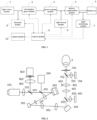
- a large field-of-view adaptive optics retinal imaging system with common optical path beam scanning in the present embodiment comprises: a light source module 1, an adaptive optics module 2, a beam scanning module 3, a defocus compensation module 4, a sight beacon module 6, a pupil monitoring module 7, a detection module 8, a control module 9 and an output module 10;
- the light source module 1, the adaptive optics module 2, the beam scanning module 3, the sight beacon module 6, the defocus compensation module 4 and the pupil monitoring module 7 are sequentially arranged along an incident optical path;
- the light source module 1 is configured to comprise a light source 101, a collimator 102 and a first beam splitter 103 that are sequentially arranged along the incident optical path, and is configured to output a parallel light beam to the adaptive optics module 2, wherein the light emitted by the light source 101 passes through the collimator 102, and is then partially transmitted through the first beam splitter 103 to enter the adaptive optics module 2.
- the light source module 1 may include a plurality of light sources 101, wherein the lights emitted from the plurality of light sources 101 may be coupled by an optical-fiber coupler and go into the collimator 102 to be collimated into a parallel light beam, or wherein the lights emitted from the plurality of light sources 101 may be collimated by corresponding collimators 102 respectively into parallel light beams which are then coupled by a dichroic beam splitter to enter the optical path; the plurality of light sources 101 may include typical fundus imaging illumination wavelengths, such as 488 nm, 515 nm, 650 nm, 680 nm, 780 nm, 830 nm and other characteristic wavelengths.
- the collimator 102 may be a single lens, an achromatic lens, an apochromatic lens or a parabolic reflector for collimating the light beam emitted by the light source 101 into a parallel light beam.
- the reflection collimator 102RC12FC-P01 of the Thorlabs Corporation is selected.
- the first beam splitter 103 is a broadband beam splitter, and its ratio of transmission to reflection is 20:80. 20% of the parallel light beam exiting from the collimator 102 is transmitted through the first beam splitter 103 and continues to propagate into the adaptive optics module 2, and 80% of the returning imaging light beam exiting from the adaptive optics module 2 is reflected by the first beam splitter 103 to enter the detection module 8.
- the first dichroic beam splitter 603 has a transmission effect on all wavelengths included in the light source 101
- the second dichroic beam splitter 702 has a transmission effect on all wavelengths included in the light source 101.
- the adaptive optics module 2 is configured to comprise a second beam splitter 201, a wavefront corrector 202, a transmissive or reflective telescope 203 and a wavefront sensor 204 that are sequentially arranged along the incident optical path, and is configured to connect to the beam scanning module 3, detect and correct wavefront aberration; the parallel light beam output by the light source module 1, after partially being transmitted through the second beam splitter 201, is reflected to the transmissive or reflective telescope 203 by the wavefront corrector 202 to enter the beam scanning module 3; the returning imaging light carrying the aberration information of the human eye and the light intensity information exits from the beam scanning module 3 and enters the transmissive or reflective telescope 203, and then is reflected to the second beam splitter 201 by the wavefront corrector 202; part of the imaging light is reflected to the wavefront sensor 204 by the second beam splitter 201 to realize measurement of wavefront aberration, and the rest of the imaging light is transmitted through the second beam splitter 201 to continue to propagate; the wavefront aberration detected by the
- the wavefront sensor 204 included in the adaptive optics module 2 is one of a microprism array Hartmann wavefront sensor, a microlens array Hartman wavefront sensor, a quadrangular pyramid sensor and a curvature sensor, and the wavefront corrector 202 is one of a deformable reflection mirror, a liquid crystal spatial light modulator, a micromachined membrane deformable mirror, a micro-electromechanical deformable mirror, a dual piezoelectric ceramic deformable mirror and a liquid deformable mirror.
- the second beam splitter 201 is a broadband beam splitter, and its ratio of transmission to reflection is 95:5. 95% of the parallel light beam output by the light source module 1 is transmitted through the second beam splitter 201 to the wavefront corrector 202; the returning imaging light beam is reflected by the wavefront corrector 202 to the second beam splitter 201, wherein 5% of the light energy of the returning imaging light beam is reflected by the second beam splitter into the wavefront sensor 204 for measuring wavefront aberration, and the remaining 95% of the light energy of the returning imaging light beam is transmitted through the second beam splitter to the first beam splitter 103 to continue to propagate.
- the detection module 8 is configured to comprise a collection lens 801, a confocal pinhole 802 and a high sensitivity detector 803, wherein the part of the returning imaging light that is transmitted through the second beam splitter 201 of the adaptive optics module 2 reaches the first beam splitter 103, and is partially reflected by the first beam splitter 103 to the collection lens 801, focused by the collection lens 801 and then passes through the confocal pinhole 802 to reach the high sensitivity detector 803, a photoelectric conversion is performed by the high sensitivity detector 803 to obtain an electrical signal, then the electrical signal is output to the control module 9 for processing to obtain a retinal imaging image, and finally the retinal imaging image is output to the output module 10 for display and storage; the confocal pinhole 802 is disposed at a focal point of the collection lens 801.
- the collection lens 801 may be an achromatic lens, an apochromatic lens or a lens combination with a focal length of no less than 100 mm.
- the confocal pinhole 802 has a size of 50 microns, which can also be changed according to the light energy efficiency while not exceeding 200 microns.
- the high sensitivity detector 803 may be a photomultiplier tube or an avalanche photodiode.
- the beam scanning module 3 is configured to comprise a first scanning mirror 301 and a second scanning mirror 303, and the two scanning mirrors are connected through a transmissive or reflective telescope 302 to achieve pupil plane matching;
- the first scanning mirror 301 is configured to perform transverse scanning of the retinal plane
- the second scanning mirror 303 is configured to perform vertical scanning of the retinal plane under the driving of a periodic voltage
- the second scanning mirror 303 is able to generate a certain transverse and vertical inclination angle under the driving of a DC voltage
- the second scanning mirror 303 is also able to perform transverse and vertical two-dimensional scanning of the retinal plane under the driving of a periodic voltage at the same time of generating the transverse and vertical inclination angle under the driving of a DC voltage
- the first scanning mirror 301 is configured to perform transverse scanning of the retinal plane
- the second scanning mirror 303 is configured to perform vertical scanning of the retinal plane under the driving of a periodic voltage
- the second scanning mirror 303 is able to generate a certain transverse and
- the first scanning mirror 301 is a resonance mirror 6SC08KA040-02Y of the Cambrige Corporation
- the second scanning mirror 303 is a fast-steering mirror MR-30-15-G-25 ⁇ 25D of the Optotune Corporation.
- the defocus compensation module 4 is configured to comprise a scanning objective lens 401, a flat-field objective lens 402 and a guide rail 403 that are sequentially arranged along the incident optical path, the light beam exiting from the beam scanning module 3 propagates to the pupil monitoring module 7 through the defocus compensation module 4, and the flat-field objective lens 402 can reciprocate along the central axis of the flat-field objective lens 402 on the guide rail 403 to achieve the compensation of refractive error of the human eye.
- the extending direction of the guide rail 403 is consistent with the direction of the central axis of the flat-field objective lens 402, and the flat-field objective lens 402 is slidably disposed on the guide rail 403.
- the flat-field objective lens 402 is configured to connect to the guide rail 403 through a motor, and the flat-field objective lens 402 is controlled via the control module 9 to reciprocate along the central axis of the flat-field objective lens 402, so as to achieve the compensation of refractive error of the human eye.
- the scanning objective lens 401 is an achromatic lens, an apochromatic lens, an aspheric lens or a lens combination with a field-of-view angle of greater than 30 degrees.
- the flat-field objective lens 402 may be an achromatic lens, an apochromatic lens, an aspheric lens or a lens combination to achieve a flat-field effect on the fundus retina.
- the sight beacon module 6 is configured to comprise an LED array 601, a lens 602 and a first dichroic beam splitter 603, wherein the light emitted by any one of LED beads in the LED array 601 after being lit by the control module 9 propagates through the lens 602, is reflected by the first dichroic mirror 603 to enter the defocus compensation module 4, and finally reaches the human eye 5, so as to allow the human eye 5 to gaze at the luminous LED bead to achieve sight fixation; the light beam exiting from the beam scanning module 3 is transmitted through the first dichroic beam splitter 603 of the sight beacon module 6, and then enters the defocus compensation module 4 to continue to propagate.
- the LED beads of the LED array 601 have a certain characteristic wavelength selected in the range of 500nm-600nm.
- the wavelength selected for the LED array 601 and the wavelength contained in the light source 101 cannot be the same, and must have a wavelength difference of more than 30nm to ensure that the first dichroic beam splitter 603 has a reflection effect on the wavelength selected for the LED array 601 and has a transmission effect on the wavelength selected for the light source 101.
- the control module 9 lighting the LED beads at different positions on the LED array 601, different areas of the fundus retina would be guided to be imaging areas.
- the pupil monitoring module 7 is configured to comprise a ring-shaped LED array 701, a second dichroic beam splitter 702, an imaging lens 703 and an area-array detector 704, wherein the light emitted by the ring-shaped LED array 701 illuminates the pupil of the human eye 5, and is reflected by the pupil of the human eye 5, passes through a hollow part of the ring-shaped LED array 701, is reflected by the second dichroic beam splitter 702, and is focused by the imaging lens 703 to the area-array detector 704, the area-array detector 704 is configured to convert light signal into an electrical signal and then output the electrical signal to the control module 9; the control module 9 is configured to obtain a pupil imaging image and finally output the pupil imaging image to the output module 10 for display and storage.
- the LED beads of the ring-shaped LED array 701 may have a near-infrared wavelength selected to be 900 nm or above, and the second dichroic beam splitter 702 has a reflection effect on the emission wavelength of the LED beads of the ring-shaped LED array 701.
- a main optical path transmission process There are multiple processes in the operation of the imaging system, including a main optical path transmission process, subject-related processes, an adaptive optics aberration measurement and correction process, and scanning imaging processes.
- the transmission optical path is as follows: the light emitted by the light source 101, approximately regarded as a point light source 101, is collimated by the collimator 102 into a parallel light beam, and is split by the first beam splitter 103, so that 20% of the parallel light beam is transmitted through the first beam splitter 103 to enter the second beam splitter 201 for light splitting; 95% of the incident light reaching the second beam splitter 201 is transmitted through the second beam splitter 201 and then is reflected by the wavefront corrector 202, and the parallel light beam continues to pass through the transmissive or reflective telescope 203 to achieve pupil aperture matching, and after being reflected by the first scanning mirror 301, the pupil aperture diameter thereof is matched by the transmissive or reflective telescope 302, and then the light beam is reflected by the second scanning mirror 303, is transmitted through the first dichroic beam splitter 603, sequentially passes through the scanning objective lens 401 and the flat-field objective lens 402, and then is transmitted through the second dichroic beam splitter 702 and passes through a hollow part
- the fundus of the human eye has a scattering effect on the incident light.
- the scattered imaging light carries the aberration information of the human eye and the light intensity information at this point on the fundus, and returns to the second beam splitter 201 along the original path.
- the scattered light is split by the second beam splitter 201 again, so that 5% of the light energy is reflected by the second beam splitter 201 into the wavefront sensor 204, and the remaining 95% of the light energy is transmitted through the second beam splitter 201 to propagate to the first beam splitter 103.
- 80% of the light reaching the first beam splitter 103 is reflected by the first beam splitter 103 into the collection lens 801, passes through the confocal pinhole 802, and reaches the high sensitivity detector 803.
- the high sensitivity detector 803 performs photoelectric conversion to obtain an electrical signal, which is then output to the control module 9 for processing. After processing, a retinal imaging image is obtained and finally output to the output module 10 for display and storage.
- the subject-related processes mainly include alignment and monitoring of pupil, compensation and correction of refractive error, guidance and fixation of a sight beacon.
- the pupil monitoring module 7 comprises a ring-shaped LED array 701, a second dichroic beam splitter 702, an imaging lens 703 and an area-array detector 704, wherein the ring-shaped LED array 701 includes at least three LED beads which are arranged along a ring at equal intervals, and the light-transmitting aperture of the hollow part thereof is no less than the diameter of the imaging light beam.
- the light emitted by the ring-shaped LED array 701 illuminates the pupil of the human eye 5, and is reflected by the pupil of the human eye 5, passes through the hollow part of the ring-shaped LED array 701, is reflected by the second dichroic beam splitter 702, and is focused by the imaging lens 703 to the area-array detector 704, the area-array detector 704 is configured to convert light signal into an electrical signal and then output the electrical signal to the control module 9; the control module is configured to obtain a pupil imaging image and finally output the pupil imaging image to the output module 10 for performing functions such as display, storage, processing.
- the headrest bracket has a three-dimensional translation adjustment function.
- the three-dimensional translatable guide rail of the headrest bracket can be manually adjusted, or the three-dimensional translatable guide rail of the headrest bracket can be configured to be driven by a motor which is driven by the control module 9 to realize automatic adjustment, so that the pupil is imaged in a central area of the field of view.
- the defocus compensation module 4 comprises a scanning objective lens 401, a flat-field objective lens 402 and a guide rail 403.
- the extending direction of the guide rail 403 is consistent with the direction of the central axis of the flat-field objective lens 402, and the flat-field objective lens 402 is slidably disposed on the guide rail 403.
- the control module 9 controls the control module 9 to reciprocate along the central axis of the flat-field objective lens to achieve the compensation of refractive error of the human eye.
- the human eye looks at the LED light emitting point to achieve sight fixation.
- the returning imaging light carrying the aberration information of the human eye and the light intensity information exits from the beam scanning module 3 and enters the transmissive or reflective telescope 203, and then is reflected to the second beam splitter 201 by the wavefront corrector 202; part of the imaging light is reflected to the wavefront sensor 204 by the second beam splitter 201 to realize measurement of wavefront aberration, and the rest of the imaging light is transmitted through the second beam splitter 201 to continue to propagate;
- the wavefront sensor 204 is configured to receive an imaging light beam containing the aberration information of the human eye and transmit the aberration information to the control module 9, and the control module 9 is configured to perform wavefront calculation, obtain a wavefront correction voltage and output the wavefront correction voltage to the wavefront corrector 202, and the wavefront corrector 202 is configured to correct aberration of the human eye in real time.
- the beam scanning module 3 comprises a first scanning mirror 301 and a second scanning mirror 303, and the two scanning mirrors are connected through a transmissive or a reflective telescope 302 to achieve pupil plane matching.
- the first scanning mirror 301 and the second scanning mirror 303 can have their front and rear positions interchanged without affecting the imaging effect.
- the first scanning mirror 301 and the second scanning mirror 303 are controlled by voltage signals output from the control module 9 and are configurable in different scanning modes for carrying out different imaging functions.
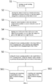
- the present application also provides a large field-of-view adaptive optics retinal imaging method with common optical path beam scanning, the method employs the above system for imaging, and comprises the following steps:
- Step S5 and Step S6 can be reversed.
- Step S61 and Step S62 are selectable to be performed according to actual needs.
- the existing laser confocal scanning ophthalmoscopes having a large field of view of imaging do not have sufficient resolution to observe fine structures of the retina; and the existing laser confocal scanning ophthalmoscopes combined with adaptive optics can observe fine structures of the retina, but have a small field of view of imaging which makes it impossible to observe lesions in a larger field of view.
- the present application proposes a large field-of-view adaptive optics retinal imaging system with common optical path beam scanning based on the basic principles of a combination of adaptive optics and confocal scanning technology, wherein two scanning mirrors are used to form a common optical path structure, the two scanning mirrors are configured in different scanning modes, which can perform large field-of-view imaging of more than 20 degrees on the retina for observing lesion distribution areas of retinal disease, and can also perform small field-of-view imaging of no more than 5 degrees on the retina, and with correction of aberration by adaptive optics, small field-of-view high-resolution imaging can be realized to observe fine structures and pathological changes of the lesion, and a second scanning mirror 302 is further configured to perform sequential tilted illumination of the light beam in each area of the retina, and then, by image stitching, a large field-of-view high-resolution imaging of the retina over 15 degrees can be acquired at one time.
- the present application proposes a large field-of-view adaptive optics retinal imaging system with common optical path beam scanning.
- the system of the present application uses two scanning mirrors to form a common optical path beam scanning structure, wherein the first scanning mirror 301 performs transverse scanning of the retina, the second scanning mirror 303 performs vertical scanning of the retina, and at the same time, the second scanning mirror 303 can also perform horizontal and vertical tilting under the driving of a DC voltage, so as to locate the illumination light beam to the area of interest on the retina.
- the first scanning mirror 301 is configured for transverse scanning
- the second scanning mirror 303 is configured for vertical scanning.
- the retinal scanning angles of the two scanning mirrors are no less than 20 degrees.
- the adaptive optics correction function is turned off to be in a shutdown state or a non-working power-on state, and a retinal imaging image with a large field of view is obtained.
- the first scanning mirror 301 is configured for transverse scanning
- the second scanning mirror 303 is configured for vertical scanning.
- the retinal scanning angles of the two scanning mirrors are no greater than 5 degrees.
- the adaptive optics module performs the aberration measurement and correction function, so as to acquire a small field-of-view high-resolution imaging image of the retina with its aberration corrected.
- the second scanning mirror 303 can also generate a transverse and vertical inclination under the driving of a DC voltage signal for locating the light beam illuminating the fundus retina at a position of interest, so as to observe a small field-of-view high-resolution imaging image of any position of interest on the retina.
- the first scanning mirror 301 is configured for transverse scanning
- the second scanning mirror 303 is configured for vertical scanning.
- the retinal scanning angles of the two scanning mirrors are no greater than 5 degrees.
- the adaptive optics module performs the aberration measurement and correction function, so as to acquire a small field-of-view high-resolution imaging image of the retina with its aberration corrected.
- the second scanning mirror 303 generates a transverse and vertical inclination angle under the driving of a DC voltage signal for locating the light beam illuminating the fundus retina at a position of interest, and the second scanning mirror 303 is configured to tilt the light beam to sequentially illuminate each area of the fundus retina, a single-time transverse and vertical inclination angle of the second scanning mirror 303 is no greater than 3 degrees, a maximum retinal transverse and longitudinal inclination angle of the second scanning mirror 303 driven by a DC voltage signal is no greater than 15 degrees.
- control module can obtain high-resolution imaging images of each area of the retina, and the control module 9 stitches the high-resolution imaging images according to the fundus retinal coordinate positions of the high-resolution imaging images of the respective areas to obtain an image of the fundus retina with a large field of view and high resolution.
- the present application provides a large field-of-view adaptive optics retinal imaging system and method with common optical path beam scanning, which can acquire a large field-of-view imaging image of the fundus retina, a small field-of-view high-resolution imaging image for any area of interest and a large field-of-view high-resolution imaging image, and the three types of imaging images are acquired by the common optical path structure, so the characteristics of the three types of imaging images have good consistency, which is convenient for processing and operation.
- the system is simple in structure, and the common optical path structure can obtain three types of retinal imaging images, and by switching between different synchronous scanning modes, it can not only observe lesion distribution areas of retinal disease by large field-of-view imaging, but also observe fine structures of a particular lesion area by small field-of-view high-resolution imaging.
- Large field-of-view imaging images can be used to observe characteristics of the structure and lesions of the retina in a wide range over the retina
- small field-of-view high-resolution imaging images can be used to observe fine structures of any area of interest
- large field-of-view high-resolution imaging images can be used to observe fine structures of the retina in a wide range.
- Multiple types of imaging images are acquired by common optical path beam scanning, which meets the requirements of different application scenarios and greatly improves the application range of retinal imaging.
Landscapes
- Health & Medical Sciences (AREA)
- Life Sciences & Earth Sciences (AREA)
- Engineering & Computer Science (AREA)
- Surgery (AREA)
- General Health & Medical Sciences (AREA)
- Biophysics (AREA)
- Biomedical Technology (AREA)
- Heart & Thoracic Surgery (AREA)
- Medical Informatics (AREA)
- Molecular Biology (AREA)
- Physics & Mathematics (AREA)
- Animal Behavior & Ethology (AREA)
- Ophthalmology & Optometry (AREA)
- Public Health (AREA)
- Veterinary Medicine (AREA)
- Signal Processing (AREA)
- Hematology (AREA)
- Nuclear Medicine, Radiotherapy & Molecular Imaging (AREA)
- Radiology & Medical Imaging (AREA)
- Vascular Medicine (AREA)
- Human Computer Interaction (AREA)
- Eye Examination Apparatus (AREA)
Claims (10)
- Netzhaut-Abbildungssystem mit adaptiver Optik und großem Sichtfeld und Strahlabtastung mit einem gemeinsamen optischen Pfad, wobei das System Folgendes umfasst: ein Lichtquellenmodul (1), ein adaptives Optikmodul (2), ein Strahlabtastmodul (3), ein Defokus-Kompensationsmodul (4), ein Sichtbakenmodul (6), ein Pupillenüberwachungsmodul (7), ein Erfassungsmodul (8), ein Steuermodul (9) und ein Ausgabemodul (10);wobei das Lichtquellenmodul (1) konfiguriert ist, um einen parallelen Lichtstrahl zu emittieren, wobei der parallele Lichtstrahl ein menschliches Auge (5) bestrahlt, nachdem er der Reihe nach durch das adaptive Optikmodul (2), das Strahlabtastmodul (3) und das Defokus-Kompensationsmodul (4) verläuft, wobei er das Licht, das von dem menschlichen Auge (5) gestreut wird, abbildet und Aberrationsinformationen des menschlichen Auges (5) transportiert und Lichtstärkeninformationen entlang eines ursprünglichen optischen Pfads des parallelen Lichtstrahls zurückgibt und das adaptive Optikmodul (2) und das Erfassungsmodul (8) erreicht;wobei das adaptive Optikmodul (2) konfiguriert ist, um das Abbildungslicht zu empfangen, das die Aberrationsinformationen des menschlichen Auges (5) transportiert, und eine Echtzeitmessung und Korrektur der Aberration des menschlichen Auges (5) durchzuführen;wobei das Strahlabtastmodul (3) durch das Steuermodul (9) gesteuert wird und das Strahlabtastmodul (3) in unterschiedlichen Abtastungsmodi zum Ausführen unterschiedlicher Abtastungsabbildungsfunktionen konfiguriert ist, die zumindest eine Abbildungsfunktion mit großem Sichtfeld, eine hochauflösende Abbildungsfunktion mit kleinem Sichtfeld und eine hochauflösende Abbildungsfunktion mit großem Sichtfeld einschließen;wobei das Defokus-Kompensationsmodul (4) konfiguriert ist, um eine Kompensation des Brechungsfehlers des menschlichen Auges (5) zu erzielen;wobei das Sichtbakenmodul (6) konfiguriert ist, um eine Sichtbake in unterschiedlichen Bereichen einer Netzhaut des menschlichen Auges (5) zu führen und fixieren;wobei das Pupillenüberwachungsmodul (7) konfiguriert ist, um eine Pupille des menschlichen Auges (5) auszurichten und zu überwachen;wobei das Erfassungsmodul (8) konfiguriert ist, um das zurückkehrende Abbildungslicht des menschlichen Auges (5) zu erfassen, das Abbildungslicht in ein elektrisches Signal umzuwandeln und das elektrische Signal zu dem Steuermodul (9) zu übertragen; undwobei das Ausgabemodul (10) konfiguriert ist, um sich mit dem Steuermodul (9) zu verbinden und Abbildungsbilder des menschlichen Auges (5) anzuzeigen und zu speichern;dadurch gekennzeichnet, dassdas Strahlabtastmodul (3) so konfiguriert ist, dass es einen ersten Abtastspiegel (301) und einen zweiten Abtastspiegel (303) umfasst, und die beiden Abtastspiegel durch ein durchlässiges oder reflektierendes Teleskop (302) verbunden sind, um eine Pupillenebenenübereinstimmung zu erzielen;der erste Abtastspiegel (301) konfiguriert ist, um eine Querabtastung der Netzhautebene durchzuführen, der zweite Abtastspiegel (303) konfiguriert ist, um eine vertikale Abtastung der Netzhautebene unter dem Ansteuern einer periodischen Spannung zum Ausführen der Abbildungsfunktion mit großem Sichtfeld durchzuführen;der zweite Abtastspiegel (303) konfiguriert ist, um einen bestimmten Quer- und vertikalen Neigungswinkel unter dem Ansteuern einer Gleichspannung zu erzeugen, wobei der zweite Abtastspiegel (303) auch konfiguriert ist, um eine zweidimensionale vertikale und Querabtastung der Netzhautebene unter dem Ansteuern einer periodischen Spannung zum selben Zeitpunkt des Erzeugens des Quer- und vertikalen Neigungswinkels unter dem Ansteuern einer Gleichspannung zum Ausführen der hochauflösenden Abbildungsfunktion mit kleinem Sichtfeld und der hochauflösenden Abbildungsfunktion mit großem Sichtfeld durchzuführen.
- Netzhaut-Abbildungssystem mit adaptiver Optik und großem Sichtfeld und Strahlabtastung mit einem gemeinsamen optischen Pfad nach Anspruch 1, dadurch gekennzeichnet, dass das Lichtquellenmodul (1), das adaptive Optikmodul (2), das Strahlabtastmodul (3), das Sichtbakenmodul (6), das Defokus-Kompensationsmodul (4) und das Pupillenüberwachungsmodul (7) der Reihe nach entlang eines auftreffenden optischen Pfads angeordnet sind;das Lichtquellenmodul (1) so konfiguriert ist, dass es eine Lichtquelle (101), einen Kollimator (102) und einen ersten Strahlteiler (103) umfasst, die der Reihe nach entlang des auftreffenden optischen Pfads angeordnet sind, und konfiguriert ist, um einen parallelen Lichtstrahl an das adaptive Optikmodul (2) auszugeben, wobei das Licht, das von der Lichtquelle (101) emittiert wird, durch den Kollimator (102) verläuft und dann teilweise durch den ersten Strahlteiler (103) übertragen wird, um in das adaptive Optikmodul (2) einzutreten;das adaptive Optikmodul (2) so konfiguriert ist, dass es einen zweiten Strahlteiler (201), einen Wellenfrontkorrektor (202), ein durchlässiges oder reflektierendes Teleskop (203) und einen Wellenfrontsensor (204) umfasst, die der Reihe nach entlang des auftreffenden optischen Pfads angeordnet sind, und konfiguriert ist, um sich mit dem Strahlabtastmodul (3) zu verbinden, die Wellenfrontaberration zu erfassen und korrigieren; wobei der parallele Lichtstrahl, der von dem Lichtquellenmodul (1) emittiert wird, nachdem er teilweise durch den zweiten Strahlteiler (201) übertragen wird, durch den Wellenfrontkorrektor (202) zu dem übertragenden oder reflektierenden Teleskop (203) reflektiert wird, um in das Strahlabtastmodul (3) einzutreten; wobei das zurückkehrende Abbildungslicht, das die Aberrationsinformationen des menschlichen Auges (5) und die Lichtstärkeninformationen transportiert, aus dem Strahlabtastmodul (3) austritt und in das durchlässige oder reflektierende Teleskop (203) eintritt und dann durch den Wellenfrontkorrektor (202) zu dem zweiten Strahlteiler (201) reflektiert wird; wobei ein Teil des Abbildungslichts durch den zweiten Strahlteiler (201) zu dem Wellenfrontsensor (204) reflektiert wird, um eine Messung der Wellenfrontaberration zu realisieren, und der Rest des Abbildungslichts durch den zweiten Strahlteiler (201) übertragen wird, um sich weiter auszubreiten;wobei der Wellenfrontsensor (204) konfiguriert ist, um einen Abbildungslichtstrahl zu empfangen, der die Aberrationsinformationen des menschlichen Auges (5) enthält, und die Aberrationsinformationen zu dem Steuermodul (9) zu übertragen, und das Steuermodul (9) konfiguriert ist, um eine Wellenfrontberechnung durchzuführen, um eine Wellenfrontspannung zu erhalten und die Wellenfrontspannung an den Wellenfrontkorrektor (202) auszugeben, um eine Wellenfrontaberration zu erfassen und korrigieren.
- Netzhaut-Abbildungssystem mit adaptiver Optik und großem Sichtfeld und Strahlabtastung mit einem gemeinsamen optischen Pfad nach Anspruch 2, dadurch gekennzeichnet, dass das Erfassungsmodul (8) so konfiguriert ist, dass es eine Sammellinse (801), eine konfokale Lochblende (802) und einen Detektor (803) mit hoher Empfindlichkeit umfasst, wobei der Teil des zurückkehrenden Abbildungslichts, das durch den zweiten Strahlteiler (201) des adaptiven Optikmoduls (2) übertragen wird, den ersten Strahlteiler (103) erreicht und teilweise von dem ersten Strahlteiler (103) zu der Sammellinse (801) reflektiert wird, von der Sammellinse (801) gebündelt wird und dann durch die konfokale Lochblende (802) verläuft, um den Detektor (803) mit hoher Empfindlichkeit zu erreichen, wobei eine fotoelektrische Umwandlung von dem Detektor (803) mit hoher Empfindlichkeit durchgeführt wird, um ein elektrisches Signal zu erhalten, dann das elektrische Signal an das Steuermodul (9) zur Verarbeitung ausgegeben wird, um ein Netzhautabbildungsbild zu erhalten, und schließlich das Netzhautabbildungsbild zur Anzeige und Speicherung an das Ausgabemodul (10) ausgegeben wird;
wobei die konfokale Lochblende (802) an einem Brennpunkt der Sammellinse (801) angeordnet ist. - Netzhaut-Abbildungssystem mit adaptiver Optik und großem Sichtfeld und Strahlabtastung mit einem gemeinsamen optischen Pfad nach Anspruch 3, dadurch gekennzeichnet, dassdie vordere und die hintere Position des ersten Abtastspiegels (301) und des zweiten Abtastspiegels (303) vertauscht sind;das Strahlabtastmodul (3) durch ein Spannungssignal gesteuert wird, das von dem Steuermodul (9) ausgegeben wird, und in unterschiedlichen Abtastungsmodi zum Ausführen von unterschiedlichen Abbildungsfunktionen einschließlich einer Abbildungsfunktion mit großem Sichtfeld, einer hochauflösenden Abbildungsfunktion mit kleinem Sichtfeld und einer hochauflösenden Abbildungsfunktion mit großem Sichtfeld konfiguriert werden kann.
- Netzhaut-Abbildungssystem mit adaptiver Optik und großem Sichtfeld und Strahlabtastung mit einem gemeinsamen optischen Pfad nach Anspruch 2, dadurch gekennzeichnet, dass das Defokus-Kompensationsmodul (4) so konfiguriert ist, dass es eine Abtastungsobjektivlinse (401), eine Flachfeldobjektivlinse (402) und eine Führungsschiene (403) umfasst, die der Reihe nach entlang des auftreffenden optischen Pfads angeordnet sind, wobei der Lichtstrahl, der aus dem Strahlabtastmodul (3) austritt, sich zu dem Pupillenüberwachungsmodul (7) durch das Defokus-Kompensationsmodul (4) ausbreitet, und sich die Flachfeldobjektivlinse (402) entlang der zentralen Achse der Flachfeldobjektivlinse (402) auf der Führungsschiene (403) hin- und herbewegen kann, um die Kompensation des Brechungsfehlers des menschlichen Auges (5) zu erzielen.
- Netzhaut-Abbildungssystem mit adaptiver Optik und großem Sichtfeld und Strahlabtastung mit einem gemeinsamen optischen Pfad nach Anspruch 2, dadurch gekennzeichnet, dass das Sichtbakenmodul (6) so konfiguriert ist, dass es ein LED-Array (601), eine Linse (602) und einen ersten dichromatischen Strahlteiler (603) umfasst, wobei das Licht, das von einer der LED-Baken in dem LED-Array (601) ausgegeben wird, nachdem es von dem Steuermodul (9) beleuchtet wurde, sich durch die Linse (602) ausbreitet, von dem ersten dichromatischen Spiegel reflektiert wird, um in das Defokus-Kompensationsmodul (4) einzutreten, und schließlich das menschliche Auge (5) erreicht, um zu ermöglichen, dass das menschliche Auge (5) auf die leuchtende LED-Bake blickt, um eine Sichtfixierung zu erzielen; wobei der Lichtstrahl, der aus dem Strahlabtastmodul (3) austritt, durch den ersten dichromatischen Strahlteiler (603) des Sichtbakenmoduls (6) übertragen wird und dann in das Defokus-Kompensationsmodul (4) eintritt, um sich weiter auszubreiten;
wobei das Pupillenüberwachungsmodul (7) so konfiguriert ist, dass es ein ringförmiges LED-Array (701), einen zweiten dichromatischen Strahlteiler (702), eine Abbildungslinse (703) und einen Flächenarraydetektor (704) umfasst, wobei das Licht, das von dem ringförmigen LED-Array (701) ausgegeben wird, die Pupille des menschlichen Auges (5) beleuchtet und von der Pupille des menschlichen Auges (5) reflektiert wird, durch einen hohlen Teil des ringförmigen LED-Arrays (701) verläuft, von dem zweiten dichromatischen Strahlteiler (702) reflektiert wird und von der Abbildungslinse (703) auf den Flächenarraydetektor (704) gebündelt wird, wobei der Flächenarraydetektor (704) konfiguriert ist, um das Lichtsignal in ein elektrisches Signal umzuwandeln und dann das elektrische Signal an das Steuermodul (9) auszugeben; wobei das Steuermodul (9) konfiguriert ist, um ein Pupillenabbildungsbild zu erhalten und schließlich das Pupillenabbildungsbild an das Ausgabemodul (10) zur Anzeige und Speicherung auszugeben. - Netzhaut-Abbildungssystem mit adaptiver Optik und großem Sichtfeld und Strahlabtastung mit einem gemeinsamen optischen Pfad nach Anspruch 4, dadurch gekennzeichnet, dass das Steuermodul (9) konfiguriert ist, um den ersten Abtastspiegel (301) und den zweiten Abtastspiegel (303) in dem Strahlabtastmodul (3) durch Ausgeben eines Spannungssignals zum Ausführen unterschiedlicher Abtastungsabbildungsfunktionen zu steuern;wobei die Abbildungsfunktion mit großem Sichtfeld durch den folgenden Prozess durchgeführt wird:das adaptive Optikmodul (2) befindet sich in einem ausgeschalteten Zustand oder einem nicht-funktionierenden eingeschalteten Zustand;der erste Abtastspiegel (301) führt die Querabtastung der Netzhautebene unter dem Ansteuern eines periodischen Spannungssignals durch; der zweite Abtastspiegel (303) führt die vertikale Abtastung der Netzhautebene unter dem Ansteuern eines periodischen Spannungssignals durch; die Netzhautabtastungswinkel des ersten Abtastspiegels (301) und des zweiten Abtastspiegels (303), die durch periodische Spannungssignale angesteuert werden, betragen nicht mehr als 20 Grad;das Erfassungsmodul (8) wandelt das erfasste Lichtsignal der Fundus-Netzhaut in ein elektrisches Signal um, das Steuermodul (9) synchronisiert die periodischen Ansteuerspannungssignale des ersten Abtastspiegels (301) und des zweiten Abtastspiegels (303), und das Steuermodul (9) tastet das elektrische Signal ab, um ein Abbildungsbild der Netzhaut mit einem großen Sichtfeld zu rekonstruieren, welches dann zur Anzeige und Speicherung an das Ausgabemodul (10) ausgegeben wird;wobei die hochauflösende Abbildungsfunktion mit kleinem Sichtfeld durch den folgenden Prozess durchgeführt wird:das adaptive Optikmodul (2) befindet sich in einem eingeschalteten Arbeitszustand, um die Wellenfrontaberration zu messen und korrigieren;der erste Abtastspiegel (301) führt die Querabtastung der Netzhautebene unter dem Ansteuern eines periodischen Spannungssignals durch; der zweite Abtastspiegel (303) erzeugt einen bestimmten Quer und vertikalen Neigungswinkel unter dem Ansteuern eines Gleichspannungssignals zum Platzieren des Lichtstrahls, der die Fundus-Netzhaut in einer interessierenden Position beleuchtet, und wird dann durch ein periodisches Spannungssignal angesteuert, um das vertikale Abtasten der Netzhautebene durchzuführen; die Netzhautabtastwinkel des ersten Abtastspiegels (301) und des zweiten Abtastspiegels (303), die durch periodische Spannungssignale angesteuert werden, sind nicht größer als 5 Grad;das Gleichspannungssignal wird durch das Steuermodul (9) gemäß einer Fundus-Netzhaut-Koordinatenposition berechnet;das Erfassungsmodul (8) wandelt das erfasste Lichtsignal der Fundus-Netzhaut in ein elektrisches Signal um, das Steuermodul (9) synchronisiert die periodischen Ansteuerspannungssignale des ersten Abtastspiegels (301) und des zweiten Abtastspiegels (303), und das Steuermodul (9) tastet das elektrische Signal ab, um ein Abbildungsbild der Netzhaut mit einem kleinen Sichtfeld und einer hohen Auflösung zu rekonstruieren, und markiert gleichzeitig die Fundus-Netzhaut-Koordinatenposition in dem Abbildungsbild; das Abbildungsbild der Netzhaut mit einem kleinen Sichtfeld und einer hohen Auflösung wird durch das Steuermodul (9) an das Ausgabemodul (10) zur Anzeige und Speicherung ausgegeben;wobei die hochauflösende Abbildungsfunktion mit großem Sichtfeld durch den folgenden Prozess durchgeführt wird:das adaptive Optikmodul (2) befindet sich in einem eingeschalteten Arbeitszustand zum Messen und Korrigieren der Wellenfrontaberration;der erste Abtastspiegel (301) führt die Querabtastung der Netzhautebene unter dem Ansteuern eines periodischen Steuersignals durch; der zweite Abtastspiegel (303) führt die vertikale Abtastung der Netzhautebene unter dem Ansteuern eines periodischen Spannungssignals durch;die Netzhautabtastwinkel des ersten Abtastspiegels (301) und des zweiten Abtastspiegels (303), die durch periodische Spannungssignale angesteuert werden, sind nicht größer als 5 Grad;zu diesem Zeitpunkt erzeugt der zweite Abtastspiegel (303) einen bestimmten Quer- und vertikalen Neigungswinkel unter dem Ansteuern eines Gleichspannungssignals, um den Lichtstrahl zu kippen, um der Reihe nach jeden Bereich der Fundus-Netzhaut zu beleuchten; ein einmaliger Quer- und vertikaler Neigungswinkel des zweiten Abtastspiegels (303) ist nicht größer als 3 Grad, ein maximaler Netzhautquer- und Längsneigungswinkel des zweiten Abtastspiegels (303), der durch ein Gleichspannungssignal angesteuert wird, ist nicht größer als 15 Grad; das Gleichspannungssignal wird durch das Steuermodul (9) gemäß einer Fundus-Netzhaut-Koordinatenposition berechnet;wenn jeder Bereich der Fundus-Netzhaut der Reihe nach durch den Lichtstrahl beleuchtet wird, kann das Steuermodul (9) hochauflösende Abbildungsbilder jedes Bereichs der Netzhaut erhalten, und das Steuermodul (9) fügt die hochauflösenden Abbildungsbilder gemäß den Fundus-Netzhaut-Koordinatenpositionen der hochauflösenden Abbildungsbilder der jeweiligen Bereiche zusammen, um ein Bild der Fundus-Netzhaut mit einem großen Sichtfeld und einer hohen Auflösung zu erhalten, welches dann zur Anzeige und Speicherung an das Ausgabemodul (10) ausgegeben wird.
- Netzhaut-Abbildungssystem mit adaptiver Optik und großem Sichtfeld und Strahlabtastung mit einem gemeinsamen optischen Pfad nach Anspruch 7, dadurch gekennzeichnet, dass das Lichtquellenmodul (1) eine Vielzahl von Lichtquellen (101) einschließt, wobei die Lichter, die von der Vielzahl von Lichtquellen (101) emittiert werden, durch einen Glasfaserkoppler gekoppelt werden und in einen Kollimator (102) hinein gelangen, um in einen parallelen Lichtstrahl kollimiert zu werden, oder wobei die Lichter, die von der Vielzahl von Lichtquellen (101) emittiert werden, durch entsprechende Kollimatoren (102) jeweils in parallele Lichtstrahlen kollimiert werden, welche dann durch einen dichromatischen Strahlteiler gekoppelt werden, um in den optischen Pfad einzutreten;der Kollimator (102) eine einzelne Linse, eine achromatische Linse, eine apochromatische Linse oder ein Parabolreflektor zum Kollimieren des Lichtstrahls, der durch die Lichtquelle (101) emittiert wird, in einen parallelen Lichtstrahl ist;der erste Strahlteiler (103) ein Breitbandstrahlteiler ist, wobei 20 % des parallelen Lichtstrahls, der aus dem Kollimator (102) austritt, durch den Strahlteiler übertragen werden und sich weiter in das adaptive Optikmodul (2) hinein ausbreiten, und 80 % des zurückkehrenden Abbildungslichtstrahls, der aus dem adaptiven Optikmodul (2) austritt, von dem ersten Strahlteiler (103) reflektiert werden, um in das Erfassungsmodul (8) einzutreten.
- Netzhaut-Abbildungssystem mit adaptiver Optik und großem Sichtfeld und Strahlabtastung mit einem gemeinsamen optischen Pfad nach Anspruch 2, dadurch gekennzeichnet, dass der Wellenfrontsensor (204), der in dem adaptiven Optikmodul (2) enthalten ist, einer eines Mikroprismaarray-Hartmann-Wellenfrontsensors, eines Mikrolinsenarray-Hartmann-Wellenfrontsensors, eines viereckigen Pyramidensensors und eines Krümmungssensors ist, und der Wellenfrontkorrektor (202) einer eines verformbaren Reflexionsspiegels, eines Flüssigkristall-Raumlichtmodulators, eines verformbaren Spiegels mit mikrobearbeiteter Membran, eines mikro-elektromechanischen verformbaren Spiegels, eines verformbaren Doppelspiegels aus piezoelektrischer Keramik und eines verformbaren Flüssigkeitsspiegels ist;
wobei 95 % des parallelen Lichtstrahls, der von dem Lichtquellenmodul (1) emittiert wird, durch den zweiten Strahlteiler (201) zu dem Wellenfrontkorrektor (202) übertragen werden; wobei der zurückkehrende Abbildungslichtstrahl von dem Wellenfronkorrektor (202) zu dem zweiten Strahlteiler (201) reflektiert wird, wobei 5 % der Lichtenergie des zurückkehrenden Abbildungslichtstrahls von dem zweiten Strahlteiler (201) in den Wellenfrontsensor (204) zur Messung der Wellenfrontaberration reflektiert werden, und die verbleibenden 95 % der Lichtenergie des zurückkehrenden Abbildungslichtstrahls durch den zweiten Strahlteiler (201) zu dem ersten Strahlteiler (103) übertragen werden, um sich weiter auszubreiten. - Netzhautabbildungsverfahren mit adaptiver Optik und einem großen Sichtfeld und Strahlabtastung mit einem gemeinsamen optischen Pfad, dadurch gekennzeichnet, dass das Verfahren das System nach Anspruch 1 zur Abbildung anwendet, wobei das Pupillenüberwachungsmodul (7) eine Kopfstützenhalterung einschließt, wobei das Defokus-Kompensationsmodul (4) eine Flachfeldobjektivlinse (402), eine Führungsschiene (403) und einen Motor zum Bewegen der Flachfeldobjektivlinse (402) auf der Führungsschiene (403) einschließt, wobei das Sichtbakenmodul (6) ein LED-Array (601) mit LED-Perlen einschließt, und wobei das Verfahren die folgenden Schritte umfasst:Schritt S1: Einschalten und Starten des Systems;Schritt S2: Platzieren des Kopfes des Subjekts auf der Kopfstützenhalterung, Einschalten des Pupillenüberwachungsmoduls (7) und manuelles Einstellen der Kopfstützenhalterung oder Verwenden des Steuermoduls (9), um die Kopfstützenhalterung automatisch zur dreidimensionalen Verschiebung einzustellen, so dass die Pupille in einem zentralen Bereich des Sichtfelds abgebildet wird;Schritt S3: manuelles Schieben der Flachfeldobjektivlinse (402) entlang der zentralen optischen Achse davon, oder Verwenden des Steuermoduls (9), um den Motor anzutreiben, um die Position der Flachfeldobjektivlinse (402) auf der Führungsschiene (403) zu bewegen, um den Brechungsfehler des menschlichen Auges (5) zu kompensieren und korrigieren;Schritt S4: Beleuchten einer LED-Perle des LED-Arrays (601) in dem Sichtbakenmodul (6), um zu ermöglichen, dass das Subjekt auf den Lichtpunkt blickt, um eine Sichtfixierung zu erzielen;Schritt S5: Schalten des adaptiven Optikmoduls (2) in einen ausgeschalteten Zustand oder einen nicht-funktionierenden eingeschalteten Zustand, Versetzen des Strahlabtastmoduls (3) in den Abtastungsmodus mit großem Sichtfeld, und Verwenden des Steuermoduls (9), um das Strahlabtastmodul (3) zu steuern, um ein Abtasten eines großen Sichtfelds durchzuführen, um ein Abbildungsbild mit großem Sichtfeld der Netzhaut zu erhalten, welches an das Ausgabemodul (10) ausgegeben wird;Schritt S6: Schalten des adaptiven Optikmoduls (2) in einen eingeschalteten Arbeitszustand, um die Wellenfrontaberration zu messen und korrigieren, und Verwenden des Steuermoduls (9), um das Strahlabtastmodul (3) zu steuern, um ein Abtasten eines kleinen Sichtfelds durchzuführen, welches zwei Abtastungsmodi S61 und S62 mit kleinem Sichtfeld einschließt;Schritt S61: Verwenden des Steuermoduls (9), um das Strahlabtastmodul (3) zu steuern, um ein hochauflösendes Abbildungsbild eines kleinen Sichtfelds zu erhalten, welches an das Ausgabemodul (10) ausgegeben wird;Schritt S62: Verwenden des Steuermoduls (9), um das Strahlabtastmodul (3) zu steuern, um ein hochauflösendes Abbildungsbild eines großen Sichtfelds zu erhalten, welches an das Ausgabemodul (10) ausgegeben wird;wobei die Sequenz des Schritts S5 und des Schritts S6 umgekehrt werden kann und der Schritt S61 und der Schritt S62 ausgewählt werden können, um ohne eine bestimmte sequentielle Beziehung durchgeführt zu werden.
Applications Claiming Priority (2)
| Application Number | Priority Date | Filing Date | Title |
|---|---|---|---|
| CN201910864687.6A CN110584592B (zh) | 2019-09-09 | 2019-09-09 | 共光路光束扫描的大视场自适应光学视网膜成像系统和方法 |
| PCT/CN2019/112687 WO2021046975A1 (zh) | 2019-09-09 | 2019-10-23 | 共光路光束扫描的大视场自适应光学视网膜成像系统和方法 |
Publications (3)
| Publication Number | Publication Date |
|---|---|
| EP3818923A1 EP3818923A1 (de) | 2021-05-12 |
| EP3818923A4 EP3818923A4 (de) | 2021-07-21 |
| EP3818923B1 true EP3818923B1 (de) | 2025-03-19 |
Family
ID=68859329
Family Applications (1)
| Application Number | Title | Priority Date | Filing Date |
|---|---|---|---|
| EP19917523.3A Active EP3818923B1 (de) | 2019-09-09 | 2019-10-23 | Selbstadaptives optisches retinabildgebungssystem mit grossem sichtfeld und verfahren mit common-path-lichtstrahlabtastung |
Country Status (6)
| Country | Link |
|---|---|
| US (1) | US12004813B2 (de) |
| EP (1) | EP3818923B1 (de) |
| JP (1) | JP7077507B2 (de) |
| KR (1) | KR102449173B1 (de) |
| CN (1) | CN110584592B (de) |
| WO (1) | WO2021046975A1 (de) |
Families Citing this family (14)
| Publication number | Priority date | Publication date | Assignee | Title |
|---|---|---|---|---|
| CN107126189B (zh) * | 2016-05-31 | 2019-11-22 | 瑞尔明康(杭州)医疗科技有限公司 | 用于视网膜成像的光学组件和视网膜成像设备 |
| US11880976B2 (en) * | 2020-03-19 | 2024-01-23 | Digital Diagnostics Inc. | Image retention and stitching for minimal-flash eye disease diagnosis |
| CN111657853B (zh) * | 2020-06-01 | 2023-04-14 | 中国科学院苏州生物医学工程技术研究所 | 高速自适应线扫描眼底成像系统及方法 |
| CN111951174B (zh) | 2020-06-16 | 2023-09-29 | 中国科学院苏州生物医学工程技术研究所 | 自适应光学线光束扫描成像的非等晕像差校正方法与装置 |
| CN111700587B (zh) * | 2020-07-29 | 2025-04-22 | 宁波大学 | 一种基于透射光学元件的自适应光学扫描激光眼底成像系统 |
| CN112641520B (zh) * | 2020-12-22 | 2022-07-05 | 北京理工大学 | 一种面向皮肤癌治疗的双模手术显微镜 |
| CN115561255B (zh) * | 2021-07-02 | 2025-07-15 | 深圳中科飞测科技股份有限公司 | 检测设备及检测方法、检测系统及存储介质 |
| CN113520304A (zh) * | 2021-07-15 | 2021-10-22 | 苏州微清医疗器械有限公司 | 显示多种光学图像分辨率的方法及共焦激光扫描成像仪 |
| US11375891B1 (en) * | 2021-12-17 | 2022-07-05 | The Trustees Of Indiana University | Methods, systems, and devices for vision testing |
| CN116919336B (zh) * | 2022-04-08 | 2025-01-21 | 南京博视医疗科技有限公司 | 一种视网膜成像方法 |
| CN114820362B (zh) * | 2022-04-24 | 2024-08-16 | 清华大学深圳国际研究生院 | 散射瞬态图像采集系统和瞬态图像校正方法 |
| CN114748034B (zh) * | 2022-05-05 | 2023-09-19 | 中国科学院光电技术研究所 | 一种基于多次散射光成像的自适应共焦检眼镜 |
| CN114903425B (zh) * | 2022-05-06 | 2024-03-12 | 山东探微医疗技术有限公司 | 一种降低对焦时人眼注视疲劳的可见光oct装置及方法 |
| CN116898392A (zh) * | 2023-08-02 | 2023-10-20 | 中国科学院苏州生物医学工程技术研究所 | 一种眼底多模态共轴成像系统 |
Family Cites Families (31)
| Publication number | Priority date | Publication date | Assignee | Title |
|---|---|---|---|---|
| CN1179702C (zh) * | 1999-07-30 | 2004-12-15 | 中国科学院光电技术研究所 | 自适应光学视网膜成像系统(4) |
| IL165212A (en) * | 2004-11-15 | 2012-05-31 | Elbit Systems Electro Optics Elop Ltd | Device for scanning light |
| WO2007127291A2 (en) * | 2006-04-24 | 2007-11-08 | Physical Sciences, Inc. | Stabilized retinal imaging with adaptive optics |
| JP4783219B2 (ja) * | 2006-06-16 | 2011-09-28 | 株式会社トプコン | 眼科撮影装置 |
| GB0907557D0 (en) | 2009-05-01 | 2009-06-10 | Optos Plc | Improvements in or relating to scanning ophthalmoscopes |
| JP5596797B2 (ja) * | 2010-01-21 | 2014-09-24 | フィジカル サイエンシーズ, インコーポレイテッド | 光学装置および眼の網膜を撮像する方法 |
| CN101862178B (zh) * | 2010-06-02 | 2012-07-11 | 中国科学院光电技术研究所 | 一种基于自适应光学的反射式共焦扫描视网膜成像系统 |
| CN101884524B (zh) * | 2010-07-20 | 2012-01-25 | 李超宏 | 基于自适应光学技术的宽视场光学相干层析仪 |
| CN101904735B (zh) * | 2010-07-20 | 2013-05-08 | 苏州微清医疗器械有限公司 | 基于快速倾斜镜的宽视场共焦扫描显微镜 |
| CN102008289A (zh) * | 2010-12-08 | 2011-04-13 | 苏州六六宏医疗器械有限公司 | 基于自动寻优算法的像差补偿眼底显微镜 |
| CN102499633B (zh) * | 2011-09-30 | 2013-09-25 | 中国科学院长春光学精密机械与物理研究所 | 大视场液晶自适应光学眼底成像的方法 |
| CN102429638B (zh) * | 2011-10-26 | 2013-11-20 | 中国科学院光电技术研究所 | 一种基于图像相关的视网膜抖动校正装置和方法 |
| CN102525406A (zh) * | 2012-02-14 | 2012-07-04 | 苏州微清医疗器械有限公司 | 一种视网膜三维成像装置 |
| CN102860815B (zh) * | 2012-09-11 | 2014-10-08 | 中国科学院光电技术研究所 | 基于线扫描共焦成像图像引导的自适应共焦扫描视网膜成像方法及装置 |
| CN102908119A (zh) * | 2012-09-26 | 2013-02-06 | 温州医学院眼视光研究院 | 一种共焦扫描成像系统及其像差控制方法 |
| WO2014059331A1 (en) * | 2012-10-12 | 2014-04-17 | Thorlabs, Inc. | Compact, low dispersion, and low aberration adaptive optics scanning system |
| CN103393400A (zh) | 2013-08-06 | 2013-11-20 | 中国科学院光电技术研究所 | 一种扫描式活体人眼视网膜高分辨力成像系统 |
| JP6394850B2 (ja) * | 2013-09-20 | 2018-09-26 | 大学共同利用機関法人自然科学研究機構 | 補償光学系及び光学装置 |
| JP2015205176A (ja) * | 2014-04-08 | 2015-11-19 | 株式会社トプコン | 眼科装置 |
| DE102014113908A1 (de) * | 2014-09-25 | 2016-03-31 | Carl Zeiss Ag | Laserscansystem |
| JP2016144530A (ja) * | 2015-02-06 | 2016-08-12 | キヤノン株式会社 | 眼科装置及びその制御方法、並びに、プログラム |
| JP6543483B2 (ja) * | 2015-02-27 | 2019-07-10 | 株式会社トプコン | 眼科装置 |
| CN104783755A (zh) * | 2015-04-29 | 2015-07-22 | 中国科学院光电技术研究所 | 自适应光学视网膜成像装置和方法 |
| JP2017136205A (ja) * | 2016-02-03 | 2017-08-10 | キヤノン株式会社 | 画像表示装置、画像表示方法及びプログラム |
| JP2017144058A (ja) * | 2016-02-17 | 2017-08-24 | キヤノン株式会社 | 眼科装置及びその制御方法、並びに、プログラム |
| WO2017190071A1 (en) | 2016-04-30 | 2017-11-02 | Envision Diagnostics, Inc. | Medical devices, systems, and methods for performing eye exams using displays comprising mems scanning mirrors |
| CN107126189B (zh) * | 2016-05-31 | 2019-11-22 | 瑞尔明康(杭州)医疗科技有限公司 | 用于视网膜成像的光学组件和视网膜成像设备 |
| EP3305175A3 (de) | 2016-10-05 | 2018-07-25 | Canon Kabushiki Kaisha | Tomographiebilderfassungvorrichtung und tomographiebilderfassungsverfahren |
| FR3065365B1 (fr) * | 2017-04-25 | 2022-01-28 | Imagine Eyes | Systeme et methode d'imagerie retinienne multi-echelle |
| WO2019117036A1 (ja) * | 2017-12-14 | 2019-06-20 | キヤノン株式会社 | 撮像装置及びその制御方法 |
| JP6578429B2 (ja) | 2018-10-22 | 2019-09-18 | 株式会社トプコン | 眼科装置 |
-
2019
- 2019-09-09 CN CN201910864687.6A patent/CN110584592B/zh active Active
- 2019-10-23 KR KR1020207028523A patent/KR102449173B1/ko not_active Expired - Fee Related
- 2019-10-23 EP EP19917523.3A patent/EP3818923B1/de active Active
- 2019-10-23 US US16/977,192 patent/US12004813B2/en active Active
- 2019-10-23 WO PCT/CN2019/112687 patent/WO2021046975A1/zh not_active Ceased
- 2019-10-23 JP JP2020551385A patent/JP7077507B2/ja active Active
Also Published As
| Publication number | Publication date |
|---|---|
| JP7077507B2 (ja) | 2022-05-31 |
| US20210121063A1 (en) | 2021-04-29 |
| US12004813B2 (en) | 2024-06-11 |
| WO2021046975A1 (zh) | 2021-03-18 |
| CN110584592B (zh) | 2021-06-18 |
| CN110584592A (zh) | 2019-12-20 |
| EP3818923A4 (de) | 2021-07-21 |
| KR102449173B1 (ko) | 2022-09-28 |
| EP3818923A1 (de) | 2021-05-12 |
| KR20210032927A (ko) | 2021-03-25 |
| JP2022518635A (ja) | 2022-03-16 |
Similar Documents
| Publication | Publication Date | Title |
|---|---|---|
| US12004813B2 (en) | Large field-of-view adaptive optics retinal imaging system and method with common optical path beam scanning | |
| US11896309B2 (en) | Retina imaging system based on the common beam scanning | |
| US11583180B2 (en) | Optical component for retinal imaging and retina imaging device | |
| US11253148B2 (en) | Ophthalmological device and ophthalmological inspection system | |
| CN110755031B (zh) | 一种眼前后节频域光相干层析成像系统 | |
| HK1209998A1 (en) | Adaptive optical retina imaging apparatus and method | |
| CN113520299B (zh) | 一种眼部多模态成像系统 | |
| CN102860815B (zh) | 基于线扫描共焦成像图像引导的自适应共焦扫描视网膜成像方法及装置 | |
| JP7443400B2 (ja) | 眼科装置及び断層画像生成装置 | |
| WO2018180730A1 (ja) | 眼科撮像装置およびその制御方法 | |
| US9339185B2 (en) | Imaging apparatus that acquires a first image and, via an aberration correction unit, a second image of an area corresponding to a part of the first image | |
| JP6494385B2 (ja) | 光画像撮像装置及びその制御方法 | |
| CN113703151B (zh) | 一种低照度可调焦间接检眼镜 | |
| JP2013248258A (ja) | 眼科装置 | |
| JP2019213751A (ja) | 眼科装置、及びその制御方法 | |
| JP2016150090A (ja) | 撮像装置及びその制御方法 | |
| JP2016168192A (ja) | 画像撮像装置及びその制御方法 | |
| CN119606303A (zh) | 用于光学视网膜成像的傅立叶域oct装置 |
Legal Events
| Date | Code | Title | Description |
|---|---|---|---|
| STAA | Information on the status of an ep patent application or granted ep patent |
Free format text: STATUS: UNKNOWN |
|
| STAA | Information on the status of an ep patent application or granted ep patent |
Free format text: STATUS: THE INTERNATIONAL PUBLICATION HAS BEEN MADE |
|
| PUAI | Public reference made under article 153(3) epc to a published international application that has entered the european phase |
Free format text: ORIGINAL CODE: 0009012 |
|
| STAA | Information on the status of an ep patent application or granted ep patent |
Free format text: STATUS: REQUEST FOR EXAMINATION WAS MADE |
|
| 17P | Request for examination filed |
Effective date: 20200907 |
|
| AK | Designated contracting states |
Kind code of ref document: A1 Designated state(s): AL AT BE BG CH CY CZ DE DK EE ES FI FR GB GR HR HU IE IS IT LI LT LU LV MC MK MT NL NO PL PT RO RS SE SI SK SM TR |
|
| A4 | Supplementary search report drawn up and despatched |
Effective date: 20210618 |
|
| RIC1 | Information provided on ipc code assigned before grant |
Ipc: A61B 3/12 20060101AFI20210614BHEP Ipc: A61B 3/14 20060101ALI20210614BHEP Ipc: A61B 3/10 20060101ALI20210614BHEP Ipc: A61B 3/113 20060101ALI20210614BHEP |
|
| STAA | Information on the status of an ep patent application or granted ep patent |
Free format text: STATUS: EXAMINATION IS IN PROGRESS |
|
| 17Q | First examination report despatched |
Effective date: 20210802 |
|
| DAV | Request for validation of the european patent (deleted) | ||
| DAX | Request for extension of the european patent (deleted) | ||
| GRAP | Despatch of communication of intention to grant a patent |
Free format text: ORIGINAL CODE: EPIDOSNIGR1 |
|
| STAA | Information on the status of an ep patent application or granted ep patent |
Free format text: STATUS: GRANT OF PATENT IS INTENDED |
|
| INTG | Intention to grant announced |
Effective date: 20241122 |
|
| GRAS | Grant fee paid |
Free format text: ORIGINAL CODE: EPIDOSNIGR3 |
|
| GRAA | (expected) grant |
Free format text: ORIGINAL CODE: 0009210 |
|
| STAA | Information on the status of an ep patent application or granted ep patent |
Free format text: STATUS: THE PATENT HAS BEEN GRANTED |
|
| AK | Designated contracting states |
Kind code of ref document: B1 Designated state(s): AL AT BE BG CH CY CZ DE DK EE ES FI FR GB GR HR HU IE IS IT LI LT LU LV MC MK MT NL NO PL PT RO RS SE SI SK SM TR |
|
| REG | Reference to a national code |
Ref country code: GB Ref legal event code: FG4D |
|
| REG | Reference to a national code |
Ref country code: CH Ref legal event code: EP |
|
| REG | Reference to a national code |
Ref country code: DE Ref legal event code: R096 Ref document number: 602019067632 Country of ref document: DE |
|
| REG | Reference to a national code |
Ref country code: IE Ref legal event code: FG4D |
|
| PG25 | Lapsed in a contracting state [announced via postgrant information from national office to epo] |
Ref country code: RS Free format text: LAPSE BECAUSE OF FAILURE TO SUBMIT A TRANSLATION OF THE DESCRIPTION OR TO PAY THE FEE WITHIN THE PRESCRIBED TIME-LIMIT Effective date: 20250619 |
|
| PG25 | Lapsed in a contracting state [announced via postgrant information from national office to epo] |
Ref country code: FI Free format text: LAPSE BECAUSE OF FAILURE TO SUBMIT A TRANSLATION OF THE DESCRIPTION OR TO PAY THE FEE WITHIN THE PRESCRIBED TIME-LIMIT Effective date: 20250319 |
|
| REG | Reference to a national code |
Ref country code: LT Ref legal event code: MG9D |
|
| PG25 | Lapsed in a contracting state [announced via postgrant information from national office to epo] |
Ref country code: NO Free format text: LAPSE BECAUSE OF FAILURE TO SUBMIT A TRANSLATION OF THE DESCRIPTION OR TO PAY THE FEE WITHIN THE PRESCRIBED TIME-LIMIT Effective date: 20250619 |
|
| PG25 | Lapsed in a contracting state [announced via postgrant information from national office to epo] |
Ref country code: HR Free format text: LAPSE BECAUSE OF FAILURE TO SUBMIT A TRANSLATION OF THE DESCRIPTION OR TO PAY THE FEE WITHIN THE PRESCRIBED TIME-LIMIT Effective date: 20250319 |
|
| PG25 | Lapsed in a contracting state [announced via postgrant information from national office to epo] |
Ref country code: LV Free format text: LAPSE BECAUSE OF FAILURE TO SUBMIT A TRANSLATION OF THE DESCRIPTION OR TO PAY THE FEE WITHIN THE PRESCRIBED TIME-LIMIT Effective date: 20250319 |
|
| PG25 | Lapsed in a contracting state [announced via postgrant information from national office to epo] |
Ref country code: GR Free format text: LAPSE BECAUSE OF FAILURE TO SUBMIT A TRANSLATION OF THE DESCRIPTION OR TO PAY THE FEE WITHIN THE PRESCRIBED TIME-LIMIT Effective date: 20250620 Ref country code: BG Free format text: LAPSE BECAUSE OF FAILURE TO SUBMIT A TRANSLATION OF THE DESCRIPTION OR TO PAY THE FEE WITHIN THE PRESCRIBED TIME-LIMIT Effective date: 20250319 |
|
| REG | Reference to a national code |
Ref country code: NL Ref legal event code: MP Effective date: 20250319 |
|
| REG | Reference to a national code |
Ref country code: AT Ref legal event code: MK05 Ref document number: 1776238 Country of ref document: AT Kind code of ref document: T Effective date: 20250319 |
|
| PG25 | Lapsed in a contracting state [announced via postgrant information from national office to epo] |
Ref country code: NL Free format text: LAPSE BECAUSE OF FAILURE TO SUBMIT A TRANSLATION OF THE DESCRIPTION OR TO PAY THE FEE WITHIN THE PRESCRIBED TIME-LIMIT Effective date: 20250319 |
|
| PG25 | Lapsed in a contracting state [announced via postgrant information from national office to epo] |
Ref country code: SE Free format text: LAPSE BECAUSE OF FAILURE TO SUBMIT A TRANSLATION OF THE DESCRIPTION OR TO PAY THE FEE WITHIN THE PRESCRIBED TIME-LIMIT Effective date: 20250319 |
|
| PG25 | Lapsed in a contracting state [announced via postgrant information from national office to epo] |
Ref country code: SM Free format text: LAPSE BECAUSE OF FAILURE TO SUBMIT A TRANSLATION OF THE DESCRIPTION OR TO PAY THE FEE WITHIN THE PRESCRIBED TIME-LIMIT Effective date: 20250319 |
|
| PG25 | Lapsed in a contracting state [announced via postgrant information from national office to epo] |
Ref country code: ES Free format text: LAPSE BECAUSE OF FAILURE TO SUBMIT A TRANSLATION OF THE DESCRIPTION OR TO PAY THE FEE WITHIN THE PRESCRIBED TIME-LIMIT Effective date: 20250319 Ref country code: PT Free format text: LAPSE BECAUSE OF FAILURE TO SUBMIT A TRANSLATION OF THE DESCRIPTION OR TO PAY THE FEE WITHIN THE PRESCRIBED TIME-LIMIT Effective date: 20250721 |
|
| PG25 | Lapsed in a contracting state [announced via postgrant information from national office to epo] |
Ref country code: PL Free format text: LAPSE BECAUSE OF FAILURE TO SUBMIT A TRANSLATION OF THE DESCRIPTION OR TO PAY THE FEE WITHIN THE PRESCRIBED TIME-LIMIT Effective date: 20250319 Ref country code: IT Free format text: LAPSE BECAUSE OF FAILURE TO SUBMIT A TRANSLATION OF THE DESCRIPTION OR TO PAY THE FEE WITHIN THE PRESCRIBED TIME-LIMIT Effective date: 20250319 |
|
| PG25 | Lapsed in a contracting state [announced via postgrant information from national office to epo] |
Ref country code: AT Free format text: LAPSE BECAUSE OF FAILURE TO SUBMIT A TRANSLATION OF THE DESCRIPTION OR TO PAY THE FEE WITHIN THE PRESCRIBED TIME-LIMIT Effective date: 20250319 |
|
| PG25 | Lapsed in a contracting state [announced via postgrant information from national office to epo] |
Ref country code: CZ Free format text: LAPSE BECAUSE OF FAILURE TO SUBMIT A TRANSLATION OF THE DESCRIPTION OR TO PAY THE FEE WITHIN THE PRESCRIBED TIME-LIMIT Effective date: 20250319 Ref country code: EE Free format text: LAPSE BECAUSE OF FAILURE TO SUBMIT A TRANSLATION OF THE DESCRIPTION OR TO PAY THE FEE WITHIN THE PRESCRIBED TIME-LIMIT Effective date: 20250319 |
|
| PG25 | Lapsed in a contracting state [announced via postgrant information from national office to epo] |
Ref country code: RO Free format text: LAPSE BECAUSE OF FAILURE TO SUBMIT A TRANSLATION OF THE DESCRIPTION OR TO PAY THE FEE WITHIN THE PRESCRIBED TIME-LIMIT Effective date: 20250319 |
|
| PG25 | Lapsed in a contracting state [announced via postgrant information from national office to epo] |
Ref country code: SK Free format text: LAPSE BECAUSE OF FAILURE TO SUBMIT A TRANSLATION OF THE DESCRIPTION OR TO PAY THE FEE WITHIN THE PRESCRIBED TIME-LIMIT Effective date: 20250319 |
|
| PG25 | Lapsed in a contracting state [announced via postgrant information from national office to epo] |
Ref country code: IS Free format text: LAPSE BECAUSE OF FAILURE TO SUBMIT A TRANSLATION OF THE DESCRIPTION OR TO PAY THE FEE WITHIN THE PRESCRIBED TIME-LIMIT Effective date: 20250719 |
|
| REG | Reference to a national code |
Ref country code: DE Ref legal event code: R097 Ref document number: 602019067632 Country of ref document: DE |
|
| PGFP | Annual fee paid to national office [announced via postgrant information from national office to epo] |
Ref country code: DE Payment date: 20251117 Year of fee payment: 7 |
|
| PG25 | Lapsed in a contracting state [announced via postgrant information from national office to epo] |
Ref country code: DK Free format text: LAPSE BECAUSE OF FAILURE TO SUBMIT A TRANSLATION OF THE DESCRIPTION OR TO PAY THE FEE WITHIN THE PRESCRIBED TIME-LIMIT Effective date: 20250319 |
|
| PLBE | No opposition filed within time limit |
Free format text: ORIGINAL CODE: 0009261 |
|
| STAA | Information on the status of an ep patent application or granted ep patent |
Free format text: STATUS: NO OPPOSITION FILED WITHIN TIME LIMIT |
|
| REG | Reference to a national code |
Ref country code: CH Ref legal event code: L10 Free format text: ST27 STATUS EVENT CODE: U-0-0-L10-L00 (AS PROVIDED BY THE NATIONAL OFFICE) Effective date: 20260128 |
|
| 26N | No opposition filed |
Effective date: 20251222 |
|
| REG | Reference to a national code |
Ref country code: CH Ref legal event code: H13 Free format text: ST27 STATUS EVENT CODE: U-0-0-H10-H13 (AS PROVIDED BY THE NATIONAL OFFICE) Effective date: 20260527 |
|
| PG25 | Lapsed in a contracting state [announced via postgrant information from national office to epo] |
Ref country code: LU Free format text: LAPSE BECAUSE OF NON-PAYMENT OF DUE FEES Effective date: 20251023 |
|
| REG | Reference to a national code |
Ref country code: BE Ref legal event code: MM Effective date: 20251031 |
|
| GBPC | Gb: european patent ceased through non-payment of renewal fee |
Effective date: 20251023 |
|
| PG25 | Lapsed in a contracting state [announced via postgrant information from national office to epo] |
Ref country code: LT Free format text: LAPSE BECAUSE OF FAILURE TO SUBMIT A TRANSLATION OF THE DESCRIPTION OR TO PAY THE FEE WITHIN THE PRESCRIBED TIME-LIMIT Effective date: 20250319 |
|
| PG25 | Lapsed in a contracting state [announced via postgrant information from national office to epo] |
Ref country code: MC Free format text: LAPSE BECAUSE OF FAILURE TO SUBMIT A TRANSLATION OF THE DESCRIPTION OR TO PAY THE FEE WITHIN THE PRESCRIBED TIME-LIMIT Effective date: 20250319 |
|
| PG25 | Lapsed in a contracting state [announced via postgrant information from national office to epo] |
Ref country code: GB Free format text: LAPSE BECAUSE OF NON-PAYMENT OF DUE FEES Effective date: 20251023 |
|
| PG25 | Lapsed in a contracting state [announced via postgrant information from national office to epo] |
Ref country code: BE Free format text: LAPSE BECAUSE OF NON-PAYMENT OF DUE FEES Effective date: 20251031 Ref country code: CH Free format text: LAPSE BECAUSE OF NON-PAYMENT OF DUE FEES Effective date: 20251031 |
|
| PG25 | Lapsed in a contracting state [announced via postgrant information from national office to epo] |
Ref country code: FR Free format text: LAPSE BECAUSE OF NON-PAYMENT OF DUE FEES Effective date: 20251031 |