EP3819080B1 - Centre de travail à contrôle électronique pour le traitement automatisé de plaques de verre ou de pierre ou d'un materiau synthétique - Google Patents
Centre de travail à contrôle électronique pour le traitement automatisé de plaques de verre ou de pierre ou d'un materiau synthétique Download PDFInfo
- Publication number
- EP3819080B1 EP3819080B1 EP20204039.0A EP20204039A EP3819080B1 EP 3819080 B1 EP3819080 B1 EP 3819080B1 EP 20204039 A EP20204039 A EP 20204039A EP 3819080 B1 EP3819080 B1 EP 3819080B1
- Authority
- EP
- European Patent Office
- Prior art keywords
- plate
- work center
- carriages
- longitudinal direction
- motorized
- Prior art date
- Legal status (The legal status is an assumption and is not a legal conclusion. Google has not performed a legal analysis and makes no representation as to the accuracy of the status listed.)
- Active
Links
Images













Classifications
-
- B—PERFORMING OPERATIONS; TRANSPORTING
- B24—GRINDING; POLISHING
- B24B—MACHINES, DEVICES, OR PROCESSES FOR GRINDING OR POLISHING; DRESSING OR CONDITIONING OF ABRADING SURFACES; FEEDING OF GRINDING, POLISHING, OR LAPPING AGENTS
- B24B7/00—Machines or devices designed for grinding plane surfaces on work, including polishing plane glass surfaces; Accessories therefor
- B24B7/005—Portal grinding machines
-
- B—PERFORMING OPERATIONS; TRANSPORTING
- B24—GRINDING; POLISHING
- B24B—MACHINES, DEVICES, OR PROCESSES FOR GRINDING OR POLISHING; DRESSING OR CONDITIONING OF ABRADING SURFACES; FEEDING OF GRINDING, POLISHING, OR LAPPING AGENTS
- B24B41/00—Component parts such as frames, beds, carriages, headstocks
- B24B41/06—Work supports, e.g. adjustable steadies
- B24B41/068—Table-like supports for panels, sheets or the like
-
- B—PERFORMING OPERATIONS; TRANSPORTING
- B24—GRINDING; POLISHING
- B24B—MACHINES, DEVICES, OR PROCESSES FOR GRINDING OR POLISHING; DRESSING OR CONDITIONING OF ABRADING SURFACES; FEEDING OF GRINDING, POLISHING, OR LAPPING AGENTS
- B24B7/00—Machines or devices designed for grinding plane surfaces on work, including polishing plane glass surfaces; Accessories therefor
- B24B7/02—Machines or devices designed for grinding plane surfaces on work, including polishing plane glass surfaces; Accessories therefor involving a reciprocatingly-moved work-table
-
- B—PERFORMING OPERATIONS; TRANSPORTING
- B24—GRINDING; POLISHING
- B24B—MACHINES, DEVICES, OR PROCESSES FOR GRINDING OR POLISHING; DRESSING OR CONDITIONING OF ABRADING SURFACES; FEEDING OF GRINDING, POLISHING, OR LAPPING AGENTS
- B24B7/00—Machines or devices designed for grinding plane surfaces on work, including polishing plane glass surfaces; Accessories therefor
- B24B7/07—Machines or devices designed for grinding plane surfaces on work, including polishing plane glass surfaces; Accessories therefor involving a stationary work-table
-
- B—PERFORMING OPERATIONS; TRANSPORTING
- B24—GRINDING; POLISHING
- B24B—MACHINES, DEVICES, OR PROCESSES FOR GRINDING OR POLISHING; DRESSING OR CONDITIONING OF ABRADING SURFACES; FEEDING OF GRINDING, POLISHING, OR LAPPING AGENTS
- B24B7/00—Machines or devices designed for grinding plane surfaces on work, including polishing plane glass surfaces; Accessories therefor
- B24B7/20—Machines or devices designed for grinding plane surfaces on work, including polishing plane glass surfaces; Accessories therefor characterised by a special design with respect to properties of the material of non-metallic articles to be ground
- B24B7/22—Machines or devices designed for grinding plane surfaces on work, including polishing plane glass surfaces; Accessories therefor characterised by a special design with respect to properties of the material of non-metallic articles to be ground for grinding inorganic material, e.g. stone, ceramics, porcelain
- B24B7/24—Machines or devices designed for grinding plane surfaces on work, including polishing plane glass surfaces; Accessories therefor characterised by a special design with respect to properties of the material of non-metallic articles to be ground for grinding inorganic material, e.g. stone, ceramics, porcelain for grinding or polishing glass
- B24B7/242—Machines or devices designed for grinding plane surfaces on work, including polishing plane glass surfaces; Accessories therefor characterised by a special design with respect to properties of the material of non-metallic articles to be ground for grinding inorganic material, e.g. stone, ceramics, porcelain for grinding or polishing glass for plate glass
- B24B7/244—Machines or devices designed for grinding plane surfaces on work, including polishing plane glass surfaces; Accessories therefor characterised by a special design with respect to properties of the material of non-metallic articles to be ground for grinding inorganic material, e.g. stone, ceramics, porcelain for grinding or polishing glass for plate glass continuous
-
- B—PERFORMING OPERATIONS; TRANSPORTING
- B24—GRINDING; POLISHING
- B24B—MACHINES, DEVICES, OR PROCESSES FOR GRINDING OR POLISHING; DRESSING OR CONDITIONING OF ABRADING SURFACES; FEEDING OF GRINDING, POLISHING, OR LAPPING AGENTS
- B24B7/00—Machines or devices designed for grinding plane surfaces on work, including polishing plane glass surfaces; Accessories therefor
- B24B7/20—Machines or devices designed for grinding plane surfaces on work, including polishing plane glass surfaces; Accessories therefor characterised by a special design with respect to properties of the material of non-metallic articles to be ground
- B24B7/22—Machines or devices designed for grinding plane surfaces on work, including polishing plane glass surfaces; Accessories therefor characterised by a special design with respect to properties of the material of non-metallic articles to be ground for grinding inorganic material, e.g. stone, ceramics, porcelain
- B24B7/24—Machines or devices designed for grinding plane surfaces on work, including polishing plane glass surfaces; Accessories therefor characterised by a special design with respect to properties of the material of non-metallic articles to be ground for grinding inorganic material, e.g. stone, ceramics, porcelain for grinding or polishing glass
- B24B7/247—Machines or devices designed for grinding plane surfaces on work, including polishing plane glass surfaces; Accessories therefor characterised by a special design with respect to properties of the material of non-metallic articles to be ground for grinding inorganic material, e.g. stone, ceramics, porcelain for grinding or polishing glass using reciprocating grinding tools
-
- B—PERFORMING OPERATIONS; TRANSPORTING
- B27—WORKING OR PRESERVING WOOD OR SIMILAR MATERIAL; NAILING OR STAPLING MACHINES IN GENERAL
- B27M—WORKING OF WOOD NOT PROVIDED FOR IN SUBCLASSES B27B - B27L; MANUFACTURE OF SPECIFIC WOODEN ARTICLES
- B27M1/00—Working of wood not provided for in subclasses B27B - B27L, e.g. by stretching
- B27M1/08—Working of wood not provided for in subclasses B27B - B27L, e.g. by stretching by multi-step processes
Definitions
- the present invention relates to electronically-controlled work centers, for processing glass plates, plates of stone material or plates of synthetic material, of the type comprising:
- the work center comprises a working head movable in three orthogonal directions to perform a cycle of processing operations on a plate positioned and locked above the horizontal working surface.
- the working head is mounted on a slide movable in the vertical direction above a carriage which is - in turn - movably mounted in a horizontal direction on a bridge-like cross-member arranged in an elevated position above the horizontal working surface.
- the bridge-like cross-member is supported at its ends on the stationary structure in such a way as to be movable in a horizontal direction orthogonal to the direction of the cross-member.
- a plate is held in a fixed position on the working surface, in a horizontal position, at a certain distance from the working surface, by means of locking devices consisting of a plurality of suction cup devices, independent of each other, which are manually positioned by an operator above the horizontal working surface, according to the shape and size of the plate to be processed.
- Each device is equipped with a lower suction cup that can be activated by vacuum to lock the unit on the working surface, and an upper suction cup that can be activated by vacuum, to hold and block a plate resting thereon.
- the Applicant has proposed a work center in his European patent application EP 1 591 427 A1 provided with a belt conveyor line for conveying a plate to be machined through a working area of the work center, starting from a plate-loading area, located upstream of the working area, up to a plate-unloading area, located downstream of the working area.
- a belt conveyor line for conveying a plate to be machined through a working area of the work center, starting from a plate-loading area, located upstream of the working area, up to a plate-unloading area, located downstream of the working area.
- the transport device of the plate is a belt device, which is not able to move the plate while ensuring that the plate is precisely in a predetermined position with respect to the conveyor belts, given the possibility of sliding of the plate with respect to the belts.
- a work center according to the preamble of claim 1 is known from WO 2017/154032 A1 .
- the transport of the plate from the loading area to the working area and from the working area to the unloading area requires the provision of dedicated additional conveyors.
- the object of the invention is to provide a work center of the type indicated at the beginning of the present description by which the positioning operation of the locking devices, which are used to hold a plate to be worked on the horizontal working surface, can be performed in a completely automatic way.
- Another object of the invention is that of achieving the aforesaid object with a relatively simple machine structure of relatively low cost and without entailing any drawbacks in terms of efficiency and operational reliability.
- Another object is to provide a work center of the type specified above, which allows the feeding of a plate to be processed to be carried out in a completely automatic manner starting from a plate loading area up to the working area in the work center, and starting from the working area up to a plate unloading area.
- Another object of the invention is to provide a work center of the type indicated above wherein also the plate loading operations onto the aforesaid loading area, and the plate unloading operations from the aforesaid unloading area can be easily automated.
- Another object of the invention is to provide a work center that can be easily adapted to simultaneously perform different processing operations on different plates, so as to be advantageously used in high-productivity plants.
- Yet another object of the invention is to provide a work center of the type specified above which has a high operating flexibility and is suitable for carrying out a variety of different processing operations on the plate.
- the invention relates to an electronically-controlled work center having the characteristics of claim 1 and a method according to claim 25.
- the aforesaid at least one working head is mounted vertically-movable on a carriage which is - in turn - horizontally movable in the aforesaid transverse direction (Y) on a bridge-like cross-member, supported by the stationary structure in an elevated position above the horizontal working surface.
- the aforesaid bridge-like cross-member is fixed with respect to the stationary structure, even if the case wherein the bridge-like cross-member is movable in the longitudinal direction (X) is not excluded, so that the relative movements between the working head and the plate in the X direction may be the result of the combination of the movement of said motorized carriages and the movement of the bridge-like cross-member.
- the preferred embodiment envisages a stationary cross-member.
- the aforesaid motorized carriages carrying the locking devices are arranged aligned with each other along the aforesaid longitudinal direction (X) and can be moved independently of each other along said longitudinal direction (X), by means of respective electric drive motors.
- the aforesaid locking devices associated with each motorized carriage consist of a horizontal coplanar array of suction cup units, facing each other, which can be operated by vacuum.
- the horizontal working surface of the stationary structure of the work center is provided with supporting and guiding members in the form of rollers and/or pads or conveyor belts, to support and guide a plate during its movement in the longitudinal direction above the working surface.
- the aforesaid suction cup units are movable between a lowered rest position and a raised operative position, wherein they are able to engage the lower surface of a plate supported on said support and guide members.
- the motorized carriages are aligned with each other along a longitudinal direction, and are arranged on one side portion of the horizontal working surface.
- the aforesaid supporting and guiding members are rollers or pads arranged in longitudinal arrays, transversely spaced apart from each other, on the other side portion of the horizontal working surface, alongside the aligned series of motorized carriages.
- each of the motorized carriages carries suction cup units arranged in longitudinal lines transversely spaced apart from each other. Between these lines there are devices for supporting the plate, which can be moved vertically between a lowered rest position and a raised operative position.
- the work center comprises at least one electronic controller for controlling electric drive motors driving the aforesaid motorized carriages.
- the electronic controller is programmed in such a way that, in a preliminary step of loading a plate on the horizontal working surface, it receives information on at least one parameter indicative of a longitudinal dimension of the plate and controls the advancement of said carriages in said longitudinal direction through respective predetermined travel lengths, so as to distribute the carriages along the plate.
- the electronic controller may control a series of synchronous movements of all the carriages to bring the plate into the working area, to impart the necessary movements to the plate in the aforesaid longitudinal direction during the execution of a cycle of processing operations on the plate by said working head, and finally to transfer the processed plate into an unloading area.
- the work center according to the invention may be equipped with several working heads designed to operate simultaneously on different plates.
- the work center is set up with several aligned series of motorized carriages carrying suction cup units, to feed several plates simultaneously through the working area.
- a machine of any type for example a Cartesian robot or a multi-axis robot
- a machine of any type for automatically loading a plate onto a loading area of the work center and/or for automatically unloading a plate from an unloading area of the work center.
- At least one tool magazine is mounted movable in the longitudinal direction (X) on the stationary structure of the work center.
- the electronic controller is programmed to control a movement of said at least one tool magazine in the longitudinal direction and a movement of said working head in the transverse direction (Y) and in the vertical direction (Z), in order to arrange the working head at the magazine, every time it is necessary to carry out an automatic tool change.
- the work center has a series of important advantages.
- the plate to be processed is held by a plurality of suction cup units, which are positioned and distributed on the working surface in a completely automatic way, according to the size and configuration of the plate.
- the work center may provide one or more contact sensors or optical sensors of any known type to detect the configuration and position of the plate with respect to the working area and thus allow automatic programming of the electronic controller regarding the arrangement of the motorized carriages carrying the suction cup units.
- An additional advantage of the work center according to the invention lies in the fact that the suction cup units carried by the motorized carriages do not hold the plate in a fixed position during processing, but, on the contrary, they move the plate in the longitudinal direction (X).
- This characteristic is used both to perform the necessary relative movements in the longitudinal direction (X) between the working head and the plate during the cycle of processing operations, and to carry out the forward movement of the plate necessary to bring the plate from the loading area to the working area and from the working area to the unloading area. Therefore, even these operations no longer require the intervention of one or more operators and can be carried out in total safety (the operators can remain outside a protected working area, since they are not required to operate in the work area) and in extremely short times, to the advantage of productivity.
- the work center according to the invention may be easily configured to simultaneously perform the processing of more than one plate.
- the degree of operational flexibility of the work center according to the invention is very high.
- the work center lends itself to be easily configured both in a manual mode, wherein relatively small plates are loaded and unloaded manually by one or more operators, and in a fully automated mode.
- the work center according to the invention also lends itself to being adapted immediately and easily for installation along an automated line, in which it constitutes a station of the line.
- said motorized carriages each carry one or more transverse rows of locking devices (typically suction cup units) aligned in transverse directions with respect to said longitudinal direction, and that each carriage has a dimension in the longitudinal direction equal to or less than the dimension in the aforesaid longitudinal direction of the locking devices carried by said carriage.
- locking devices typically suction cup units
- This solution makes it possible to arrange the suction cup units carried by different carriages into positions immediately adjacent to each other, placing the carriages in contact with each other. Furthermore, this solution allows, in the event that the work center is equipped with a second and lower drilling head, minimizing the minimum distance between the suction cup unit and the lower drilling head, allowing a greater dimension of the area of the plate in which it is possible to make a hole.
- the horizontal working surface of said stationary structure is provided with an array of conveyor belts parallel and transversely spaced apart, to support and guide a plate during its movement in the longitudinal direction entering and/or exiting the working surface.
- the said conveyor belts are movable between a lowered rest position and a raised operative position, wherein they are able to engage the lower surface of a plate so as to support the plate and transfer the plate in the longitudinal direction.
- the locking devices carried by the motorized carriages are suction cup units that can are displaceable in the spaces between the conveyor belts between a lowered rest position and a raised operative position, wherein the suction cup units are able to engage the lower surface of a plate supported on said conveyor belts.
- said one or more motorized carriages carrying the locking devices are also used to support waste portions of the glass plates resulting from processing operations on the plates.
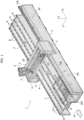
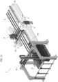
- reference 1 indicates - in its entirety - an electronically-controlled work center for processing glass plates, plates of stone material or plates of synthetic material.
- the work center 1 comprises a stationary structure 2, defining a horizontal working surface 3.
- the horizontal working surface 3 includes a working area generally indicated by A, surmounted by a bridge-like cross-member 4 arranged in an elevated position above the working area A.
- the bridge-like cross-member 4 is in a fixed position with respect to the stationary structure 2, having its ends carried by two side portions 5, which are rigidly connected to the stationary structure 2.
- the horizontal working surface 3 extends in a longitudinal horizontal direction X, while the bridge-like cross-member 4 extends in a transverse horizontal direction Y, orthogonal to the longitudinal direction X.
- a motorized carriage 6 is slidably mounted on the bridge-like cross-member 4 in the Y direction.
- a slide 7 carrying a working head H.
- the plates L are displaced in the direction X above the horizontal working surface 3 by means of a plurality of motorized carriages C, movable in the longitudinal direction X independently of each other and carrying a plurality of locking devices V configured for engaging and blocking one or more plates, kept in a horizontal position, on said carriages.
- the locking devices consist of suction cup units which can be operated by vacuum.
- the relative movements of the working head H with respect to the plate are obtained: in the X direction by the movement of the plate imparted by the motorized carriages C; in the Y direction by the movement of the carriage 6 along the bridge-like cross-member 4, and in the Z direction by the movement of the slide 7.
- Respective electric motors are provided for driving the movements of the carriages C in the longitudinal direction X; of the carriage 6 in the transverse direction Y, and of the slide 7 in the vertical direction Z.
- These electric motors are controlled by one or more electronic controllers E (see, for example, Figure 15 ), which in the illustrated embodiment example are arranged inside a cabinet associated with the stationary structure 5, which supports one end of the bridge-like cross-member 4.
- the electronic controller is equipped with a human-machine interface HMI including, for example, a monitor 10 and a keyboard 11.
- the number 8 indicates a spindle supported by the slide 7 in a rotatable way around a vertical axis, with an electric drive motor associated therewith.
- the spindle 8 has a lower end having a seat for receiving and removably supporting the conical shank 9 of a tool G (for example, a grinding wheel with a vertical axis), by means of a coupling device of any known type, configured for allowing an automatic tool change.
- a tool assembly G1 is coupled to the spindle 8, of the type illustrated - by way of example - in Figure 5 , having a conical shank 9 for coupling with the spindle 8.
- the shank 9 is connected in rotation by means of a pair of bevel gears (not illustrated) with a tool G2 (in the example a cup wheel) with a horizontal axis.
- the motorized carriages C are arranged aligned with each other in the longitudinal direction X adjacent to one side of the stationary structure 2, and are movable within a channel 200 ( Figure 1 ) defined by the stationary structure 2, below the horizontal working surface 3.
- a channel 200 ( Figure 1 ) defined by the stationary structure 2, below the horizontal working surface 3.
- longitudinal arrays of rollers R are arranged, freely rotatable around horizontal transverse axes.
- the longitudinal arrays of rollers R are transversely spaced apart.
- the plate L is intended to rest partly on the carriages C and partly on the longitudinal arrays of rollers R.
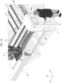
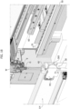
- FIGS. 3 and 4 of the attached drawings show the detail of a motorized carriage C carrying a plurality of suction cup units V.
- the suction cup units V are arranged along several spaced apart longitudinal lines, and have coplanar upper suction cups, lying in the same horizontal plane.
- Each suction cup unit is not described here in its construction details, as it can be made in any known way.
- each suction cup unit comprises a suction cup facing upwards, operated by vacuum.
- the suction cup units comprise - in a known way - inner chambers (not visible in the drawings) communicating via flexible pipes (also not illustrated) with a vacuum source, typically a pump.
- This pump may be located on board the respective carriage C, and operated by a respective electric motor, also located on board the carriage C.
- the pump that generates the vacuum may be a single pump that serves all the carriages C, located in an area of the stationary structure.
- the management of the vacuum is made independent for the various suction cup units by means of solenoid valves, each associated with a respective suction cup unit, which are governed by the central electronic control unit of the machine, depending on the size and shape of the plate to be processed.
- the suction cup units V are associated with one or more actuators of any known type (for example, fluid actuators) so as to be movable between a lowered rest position and a raised operating position, wherein the suction cups engage the lower surface of a plate L resting on the rollers R of the longitudinal arrays of rollers described above (see in particular Figure 4 ).
- each carriage C can be operated independently from that of the other carriages C.
- each carriage C is equipped with an electric motor assembly M that rotates a pinion P meshing with a rack D carried by the stationary structure 2 of the machine and extending in the longitudinal direction X.
- each carriage C is supported in a cantilever fashion and guided in its sliding movement in the X direction by means of pads 12, which engage guide bars 13 carried by the stationary structure 2 and extending in the longitudinal direction X.
- a structure C1 is associated with each motorized carriage C for containing and guiding the electrical power cables of the electrical devices located on board the carriage C, which is - in turn - connected to a catenary structure C2 (see in particular, Figure 4 ) serving to guide the aforesaid cables during the movement of the respective carriage.
- pad supports 15 are interposed, vertically-movable, with respect to the structure of the carriage (by means of fluid actuators, not illustrated), between a raised operational position and a lowered rest position.
- the supports 15 When the suction cup units of a carriage are in their lowered position, the supports 15 may be in their raised position, so that a plate L (see, for example, Figure 7 ) may be supported partly on the rollers R, in its left portion, with reference to the direction of movement of the plate (indicated by the arrow X1 in Figure 1 ) and partly on the pads of the supports 15 of the carriages C, leaving the plate free to slide forward.
- the work center provides a device 14 (see again, in particular, Figures 1-4 ), to position a plate to be processed in the transverse direction Y.
- the device 14 comprises a longitudinal bar 140, extending in the X direction carrying a plurality of vertical axis rollers 141.
- the longitudinal bar 140 can be operated by means of actuators 140A (one of which is illustrated in Figure 2 ) so as to be displaceable in the transverse direction Y in order to push the longitudinal array of rollers 141 against the right side edge of the plate L, with reference to the advancing direction of the plate (indicated by the arrow X1 in Figure 1 ), in order to push the plate into a strictly predetermined transverse position.
- the plate L In an initial step of loading a plate L on a loading area A0, at one end of the stationary structure 2 (see Figures 6 and 7 , the plate L is placed above the arrays of rollers R and on the supports 15 of the carriages C, without yet activating the suction cup units V. In this condition, the plate is positioned to the right (with reference to the advancing direction X1) beyond the correct working position.
- the bar 140 of the transverse reference device 14 is actuated so as to engage the right side edge of the plate with the rollers 141, and push the plate transversely up to a correct working position.
- the actuator or actuators of the transverse movement of the bar 14 are controlled by the electronic controller E of the work center, according to a predetermined program.
- the longitudinal bar 140 of the device 14 Once the longitudinal bar 140 of the device 14 has been positioned in this way, it remains in this position, so as to define the zero line, or faith line, for the plate during all the movements that the plate performs during the transfer step from the loading area to the working area, during the cycle of processing operations and during the transfer from the working area to the unloading area.
- Figures 6-11 show the different steps of loading a plate onto the working surface, according to an embodiment example.
- Figure 6 shows four carriages C carrying the suction cup units V, all arranged in mutually adjacent positions at the loading area A0 of the plate.
- the plate is schematically illustrated in a position still distant from the loading area A0.
- the work center according to the invention can be associated with devices for automatically loading and unloading the plates, even if it is not excluded, especially in the case of small sized plates, that the loading and unloading operations can be performed manually, as illustrated in Figure 13 .
- the operator can also perform a similar manual operation for unloading the plate from the unloading area of the work center.
- the work center constitutes only one station interposed along an automated processing line, in which case the loading area A0 receives the plate from the station located in the line immediately upstream of the work center.
- Figure 7 shows the plate L having arrived in a position wherein its front part overlaps the suction cup units carried by all carriages C. In this condition, the suction cup units of all the carriages are in their inoperative lowered position, with the exception of the suction cup units of the first carriage, located in the most advanced position, towards the working area A.
- Figure 8 shows precisely the condition wherein the suction cup units of the first carriage have been carried into their raised position and activated to hold the front part of the plate L thereon.
- the electronic controller of the work center activates, in a completely automatic way, according to a predetermined program, or if necessary following commands given by an operator, only the movement in the X direction of the aforesaid first carriage, while the remaining carriages are left stationary in position, with the suction cup units deactivated.
- the first carriage drags the plate L up to the position illustrated in Figure 9 , adjacent to the working area, making the plate slide over the rollers R and over the supports 15 (which are in the raised position) of the remaining carriages C at the loading area A0.
- the first carriage is kept with its suction cup units active and in engagement with the lower surface of the plate, while the other carriages C are advanced in succession, with their suction cup units in the lowered position, for different predetermined strokes, until they are distributed in mutually spaced positions along the plate, so as to cover the entire extension of the plate ( Figures 10, 11 ).
- the movement of these carriages can also be activated simultaneously with the movement of the first carriage.
- the suction cup units V are automatically distributed along the length of the plate, according to the size of the plate itself and the processing operations to be carried out.
- the plate rests on the suction cup units of the various carriages, which - at this point - are all carried into their raised operational position and made active, to hold the plate thereon.
- the plate also rests with its left part above the arrays of rollers R.
- the aforesaid operations may be controlled by the operator through the HMI interface, but more preferably they are obtained completely automatically by the electronic controller E, on the basis of a predetermined program, which is a function of the dimensions (including the thickness) of the plate, of the configuration of the plate, and the processing operations to be carried out.
- the work center is preferably equipped with sensor devices of any known type, for example, contact sensors or optical sensors (not illustrated), capable of detecting the presence of the plate and its dimensions, to allow automatic programming of the distribution of the carriages C along the plate.
- sensor devices of any known type, for example, contact sensors or optical sensors (not illustrated), capable of detecting the presence of the plate and its dimensions, to allow automatic programming of the distribution of the carriages C along the plate.
- the electronic controller and the machine may activate any cycle of processing operations programmed for processing of the plate.
- the working head H is brought alongside the portions of the plate L intended to be processed. This is achieved by moving the working head H in the Y direction and in the Z direction by moving the carriage 6 and the slide 7, and controlling a synchronous movement of all the carriages C to cause the necessary movements of the plate L (forwards or backwards) in the longitudinal direction X.
- the movement of the carriages is controlled to bring the front edge of the plate against a contact sensor, with an electric microswitch that sends a signal to the control unit indicating the starting position of the plate, with respect to the longitudinal direction X.
- the work center is designed to perform a wide range of processing operations, thanks to the provision of one or more tool magazines, which are designed to allow a fully automatic tool change on the working head H, depending on the processing to be performed.
- the work center 1 is equipped with two tool magazines.
- a first tool magazine U1 is carried by a cross-member 20 arranged parallel to and adjacent to the bridge-like cross-member 4.
- the cross-member 20 is supported by the stationary structure 2 so as to be displaceable in the X direction.
- the magazine U1 comprises a plurality of tool-holder members, made in any known way, to allow automatically depositing or picking-up of a tool assembly.
- the movements in the longitudinal direction X of the cross-member 20 with respect to the bridge-like cross-member 4 are controlled by a pneumatic actuator or, alternatively, by an electric motor (not illustrated), and are controlled by the electronic controller E of the machine.
- a second tool magazine U2 is carried by the stationary structure to a lower position than the first magazine U1.
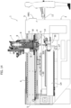
- Figure 19 illustrates a cross-sectional view of the work center 1, in a vertical plane parallel to the X direction.
- the magazine U2 is carried by a beam 21 extending in a direction parallel to the longitudinal direction X, and displaceable with respect to the stationary structure of the work center along said longitudinal direction X.
- the movements of the structure 21 are controlled by an electric motor (not illustrated) under the control of the electronic controller E of the work center.
- the magazine U2 supports a plurality of tool-holder members - of any known type - to support a plurality of tool assemblies, for example, tool assemblies G1 of a type similar to that illustrated in Figure 5 , with a tool having a horizontal axis connected in rotation by means of a pair of bevel gears with a conical shank 9 having a vertical axis.
- the work center is also able to perform drilling operations, thanks to the use, in combination with the working head H, which operates above the plate, of a lower auxiliary working head LH, which operates under the plate.
- a plate drilling operation in particular, in the case of glass plates, involves the simultaneous engagement of the plate by an upper tool and a lower tool.
- the lower head LH is in the form of a transverse beam, which is slidably guided along the transverse direction Y under the stationary structure 2 of the work center.
- guide bars 25 (see Figure 19 ) slidably mounted inside guide supports 26 carried by the stationary structure may be arranged on the lower side of the beam constituting the structure of the lower cross-member LH, and/or a wheel 27 ( Figure 16 ) may be provided, always on the lower side of the head LH, and at one of its ends, freely rotatable around a horizontal axis parallel to the X direction and shaped like a pulley, so as to be guided and - at the same time - held transversely on a guide rail 28 carried by the stationary structure, in order to avoid bending during translation in the Y direction, and in order to react to the shear stress in the Z direction.
- the structure of the lower cross-member LH carries a revolver device 30, rotatable around a horizontal axis parallel to the transverse direction Y, carrying a star-like arrangement of tools 300, which are selectable according to the operation to be performed.
- the revolver device 30 is rotated so as to bring the tool to be used in the North position of the star of tools 300.
- the plate When it is necessary to perform a drilling operation on a plate L, the plate is moved in the X direction, by means of the carriages C, together with a positioning of the lower head LH along the Y direction and a positioning of the upper head H along the direction Y, respectively, below and above the plate at the point on the plate where the drilling is to be performed.
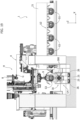
- FIG. 17 With reference to Figure 17 , inside the structure constituting the lower head LH, there is an electric motor unit M1, which is able to rotate, by means of a transmission of any known type (not illustrated), the tool 300, which is in the upper operating position in the tool star 300. Furthermore, the structure that carries the tool 300 which is in the operative position is also provided with an actuator (not shown) for imparting a movement in the Z direction to the tool 300.
- Figure 17 shows the conical shank 9 of a drilling tool G intended to engage the glass plate from the upper side. For greater clarity, Figure 17 does not illustrate the electro-spindle, to which the conical shank 9 is coupled.
- Figures 17 , 18 also show a wall W carried by the upper working head H, which surrounds the tool G when the tool is in the working position, and is intended to support nozzles for the emission of coolant liquid (not illustrated).
- a ring structure 40 surrounds the lower tool 300 when it is lowered into an operating position), and is equipped with nozzles (not illustrated) for the emission of coolant in the working area of the lower tool.
- the ring structure 40 also has a movement in the Z direction that allows it to position itself at the level of the lower surface of the plate to act as a support surface during the drilling operation.
- Figures 17 and 18 also show a cross-member 50 carried by the stationary structure and provided at the top with a series of rollers 51, aligned in the transverse direction Y, and freely rotatable around a transverse axis.
- a cross-member 50 carried by the stationary structure and provided at the top with a series of rollers 51, aligned in the transverse direction Y, and freely rotatable around a transverse axis.
- the plate L is also guided in its movements on the working area by an upper containment structure 60 ( Figure 14 ), suspended from the bridge-like cross-member 4 in a vertically adjustable position (by means of a fluid actuator not illustrated), above the plate and equipped with pad elements or freely rotating rollers, for engagement with the upper surface of the plate.
- an upper containment structure 60 Figure 14
- the bridge-like cross-member 4 suspended from the bridge-like cross-member 4 in a vertically adjustable position (by means of a fluid actuator not illustrated), above the plate and equipped with pad elements or freely rotating rollers, for engagement with the upper surface of the plate.
- Figures 15 and 16 show the lower head LH, respectively, in its two positions at opposite ends of its stroke in the Y direction.
- the carriages C are controlled simultaneously to transport the plate L to the position illustrated in Figure 12 , wherein the front portion of the plate is at the unloading area AF.
- the suction cup units of the carriages C may be deactivated and carried to their inoperative lowered positions, with the exception of the last carriage, which is further back with respect to the advancing direction of the plate.
- This carriage can be kept with its suction cup units in engagement with the plate, and then be made to advance in the X direction (the remaining carriages will, in any case, be advanced to avoid interference) so as to push the plate L towards an unloading position from the work center.
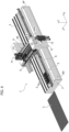
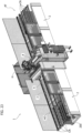
- Figure 20 shows another embodiment, wherein the configuration of the work center described above with reference to Figures 1-19 is doubled in a specular way, with two aligned series of carriages C arranged side-by-side, to simultaneously carry two plates L to be processed by two working heads H carried on the bridge-like cross-member.
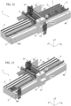
- Figures 21 , 22 illustrate embodiments wherein the work center described above is associated with a machine for automatically loading the plates onto the work center.
- a Carriageesian robot 70 is arranged, carrying a gripper 71 equipped with vacuum-operated suction cup units, which is moved to subsequently pick up the plates from a support rack of the plates, and to deposit them on the working surface of the work center.
- Figure 22 illustrates a solution in which the gripper 71 is carried by a multi-axis manipulator robot 72.
- the work center can be used flexibly in a variety of ways, including a manual loading and unloading mode of small plates by one or more operators.
- the work center according to the invention may be inserted into an automated production line, so that the loading area of the work center receives, in succession, the plates that are fed by the station of the automated line, which is located upstream of the work center. Similarly, at its unloading end, the work center feeds the processed plate to the station of the automated line located downstream from the work center, or to a final unloading station for the processed plate, to which the plate is sent for shipment.
- Figures 23-27 refer to an additional embodiment of the work center according to the invention, that allows the automated feeding and processing of glass plates even with relatively small dimensions (for example, with a longitudinal dimension in the order of 400 mm).
- the working surface 3 is provided with a plurality of closed-loop conveyor belts CN arranged in the longitudinal direction of the work center, all parallel to each other and transversely spaced apart from each other, to support and guide the glass plates entering and leaving the work center.
- the conveyor belts CN also cover the area of the working surface 3 next to the channel 200 wherein the motorized carriages C are movable.
- the conveyor belts CN can be moved vertically between a raised operating position, wherein they are able to feed a glass plate entering and leaving the work center, and a lowered position, wherein they release the glass plate carried by them above the suction cup units V carried from the motorized carriages C.
- the carriages C each carry a row of suction cup units V arranged transversely to the longitudinal direction, with the suction cup units V of each carriage being transversely spaced from each other, so that the carriages C are free to move below the conveyor belts CN, and the conveyor belts CN are arranged in the spaces between the suction cup units V.
- a roller surface RS can be provided, on which a glass plate L can be made to advance until it is picked up from the conveyor belts CN.
- each motorized carriage C carries one or more rows of suction cup units V directed transversely to the longitudinal direction of the work center (the example of Figures 23-27 shows motorized carriages C each having a single transverse row of suction cup units V), and each carriage C has a dimension in the longitudinal direction of the work center that is less than or equal to the dimension in the longitudinal direction of the suction cup units V carried by the carriage C.
- the suction cup units V carried by different carriages in positions strictly adjacent to each other, by arranging the carriages C in contact with each other, or in positions strictly adjacent to each other, as shown in Figures 24-26 .
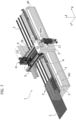
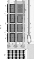
- Figure 23 of the attached drawings is an overall perspective view of the embodiment described here, while Figures 24-26 are plan views of a detail of the loading area AO in three different operating conditions.
- Figure 4 shows a plate L in the step wherein it is transferred from the roller surface RS to two conveyor belts CN of the loading area AO. In this step, four motorized carriages C are kept in positions adjacent to each other in the loading area AO, below the conveyor belts CN.
- the step of Figure 25 shows a subsequent step, wherein the motorized carriages C have remained in their positions, while the plate L has been moved to an advanced position by the two conveyor belts CN that engage its lower surface.
- Figure 26 shows the same condition as Figure 25 , wherein, however, the longitudinal bar 14 is advanced transversely (towards the other with reference to Figure 26 ) to position the plate L in the correct position.
- the conveyor belts CN may be lowered so as to deposit the plate L on one or more suction cup units V of one or more carriages C.
- suction cup units of one or more motorized carriages C are also used to support waste portions of the glass plates resulting from processing operations on the plates.
- the suction cup units V that engage a waste portion can be moved vertically between a raised operative position and a lowered position, wherein they keep the picked-up waste portion out of the encumbrance of the working area.
- the conveyor belts CN also cover the part of the working surface 3 located next to the channel 200 in which the motorized carriages C are movable.
- the work center has a series of important advantages.
- the plate to be processed is held by a plurality of suction cup units, which are positioned and distributed on the working surface in a completely automatic way, according to the dimensions (including thickness) of the plate, the configuration of the plate, and the processing operations to be carried out.
- the work center can provide one or more contact sensors or optical sensors of any known type to detect the configuration and position of the plate with respect to the working area, and thus allow automatic programming of the electronic controller regarding the arrangement of the motorized carriages carrying the suction cup units.
- a further advantage of the work center according to the invention lies in the fact that the suction cup units carried by the motorized carriages no longer hold the plate in a fixed position during processing but, on the contrary, move the plate in the longitudinal direction (X).
- This characteristic is used both to perform the necessary relative movements in the longitudinal direction (X) between the working head and the plate during the cycle of processing operations, and to carry out the forward movement of the plate necessary to carry the plate from the loading area to the working area and from the working area to the unloading area. Therefore, even these operations no longer require the intervention of one or more operators and can be carried out in total safety (the operators can remain outside a protected working area, not needing to intervene near the area of work) and in extremely short times, to the advantage of productivity.
- the work center according to the invention can be easily configured to simultaneously perform the processing of more than one plate.
- the degree of operational flexibility of the work center according to the invention is very high.
- the work center lends itself to be easily configured both in a manual mode, wherein relatively small plates are loaded and unloaded manually by one or more operators, and in a fully automated mode.
- the work center according to the invention also lends itself to being adapted immediately and easily for installation along an automated line, in which it constitutes a station on the line.
- sensors for detecting the presence of the plate are arranged along the longitudinal direction, capable of detecting its size in the longitudinal direction of movement, in order to communicate this information to the electronic control unit, to facilitate the determination of the correct position of the carriages C.
- sensors for detecting the presence of the plate are arranged along the longitudinal direction, capable of detecting its size in the longitudinal direction of movement, in order to communicate this information to the electronic control unit, to facilitate the determination of the correct position of the carriages C.
- an automatic measurement system can be provided that detects the dimensions of the plate in the advancing direction X and in the transverse directions Y and Z, and communicates the data collected thereby to a central electronic controller.
- the senor capable of detecting the initial position of the plate along the longitudinal direction cooperates with a portion of the plate located sufficiently far away from an edge between the lower surface and a vertical side surface of the plate, so as to avoid detection of metal scraps present on the plate following previous cutting processes.
- said sensor is configured and arranged to cooperate with an upper part of the thickness of the plate being processed (L).
Landscapes
- Engineering & Computer Science (AREA)
- Mechanical Engineering (AREA)
- Life Sciences & Earth Sciences (AREA)
- Chemical & Material Sciences (AREA)
- Ceramic Engineering (AREA)
- Inorganic Chemistry (AREA)
- Wood Science & Technology (AREA)
- Forests & Forestry (AREA)
- Specific Conveyance Elements (AREA)
Claims (33)
- Centre de travail à contrôle électronique pour traiter des plaques de verre, des plaques de pierre ou des plaques de matériau synthétique, comprenant :une structure fixe (2) définissant une surface de travail horizontale (3),une pluralité de dispositifs de blocage (V) pour retenir une plaque (L) dans une position horizontale au-dessus et à une distance de la surface de travail horizontale (3),au moins une tête de travail (H) portée dans une position élevée au-dessus de la surface de travail horizontale (3) et pouvant réaliser des mouvement relatifs - par rapport à une plaque (L) retenue par lesdits dispositifs de blocage (V) - dans une direction horizontale longitudinale (X), dans une direction horizontale transversale (Y) perpendiculaire à la direction longitudinale et dans une direction verticale (Z),dans lequel ladite pluralité de dispositifs de blocage (V) est portée par un ou plusieurs chariots motorisés (C), mobiles le long de ladite direction horizontale longitudinale (X) par rapport à ladite structure fixe, etun organe de contrôle électronique programmé pour contrôler le mouvement desdits chariots motorisés (C) portant les dispositifs de blocage (V) dans ladite direction longitudinale (X), afin de déplacer une plaque (L) dans la direction longitudinale (X) dans une zone de travail (A), pendant l'exécution d'un cycle de travail, de sorte que pendant le traitement d'une plaque (L) retenue au moyen desdits dispositifs de verrouillage (V), les mouvements relatifs de la tête de travail (H) par rapport à la plaque (L) le long de ladite direction longitudinale (X) sont obtenus au moyen d'un mouvement desdits un ou plusieurs chariots motorisés (C),ledit centre de travail étant caractérisé en ce que ledit organe de contrôle électronique est programmé pour déplacer lesdits chariots motorisés (C) à travers ladite zone de travail (A) dudit centre de travail, à partir d'une première partie d'extrémité de ladite structure fixe (2), dans lequel une plaque (L) peut être chargée sur ou déchargée desdits un ou plusieurs chariots motorisés (C) portant les dispositifs de blocage (V), jusqu'à une deuxième partie d'extrémité de ladite structure fixe (2), dans lequel une plaque (L) peut être déchargée de ou chargée sur lesdits un ou plusieurs chariots motorisés (C) portant les dispositifs de blocage (V),de sorte que lesdits chariots motorisés (C) sont utilisés également pour déplacer une plaque dans la direction longitudinale (X) afin de la prendre de la zone de chargement de plaque (A0) à la zone de travail (A),et également pour déplacer une plaque dans la direction longitudinale (X) afin de la prendre de la zone de travail de plaque (A0) à la zone de déchargement de plaque (A).
- Centre de travail selon la revendication 1, caractérisé en ce que ladite tête de travail (H) est montée de manière verticalement mobile sur un chariot (6) qui est - à son tour - horizontalement mobile dans la direction horizontale transversale (Y) mentionnée précédemment sur une traverse en forme de pont (4), ayant des extrémités opposées supportées par ladite structure fixe (2) dans une position élevée au-dessus de la surface de travail horizontale (3).
- Centre de travail selon la revendication 2, caractérisé en ce que ladite traverse en forme de pont (4) est rigidement raccordée à la structure fixe (2).
- Centre de travail selon la revendication 1, caractérisé en ce qu'il comprend une pluralité de chariots (C) portant les dispositifs de blocage (V) agencés alignés les uns par rapport aux autres le long de ladite direction longitudinale (X) et pouvant être déplacés indépendamment les uns des autres le long de ladite direction longitudinale (X), au moyen de moteurs d'entraînement électriques (M) respectifs.
- Centre de travail selon la revendication 1, caractérisé en ce que les dispositifs de blocage (V) associés à chaque chariot motorisé (C) se composent d'une rangée coplanaire horizontale d'unités à ventouse (V) tournées vers le haut, pouvant être actionnées sous vide.
- Centre de travail selon la revendication 5, caractérisé en ce que la surface de travail horizontale (3) de ladite structure fixe (2) est prévue avec des éléments de support et de guide (R, CN), en forme de rouleaux (R) ou de patins ou de courroies transporteuses (CN), pour supporter et guider une plaque (L) pendant son mouvement dans la direction longitudinale sur la surface de travail (3), et
en ce que les unités à ventouse (V) sont mobiles entre une position de repos abaissée et une position opérationnelle levée, dans lequel elles sont en mesure de mettre en prise la surface inférieure d'une plaque (L) supportée sur lesdits éléments de support et de guide. - Centre de travail selon la revendication 6, caractérisé en ce que lesdits chariots motorisés (C) sont alignés les uns par rapport aux autres le long d'une direction longitudinale et sont agencés sur une partie latérale de ladite surface de travail horizontale (3) et en ce que lesdits éléments de support et de guide sont des rouleaux (R) ou des patins agencés dans des rangées longitudinales qui sont mutuellement espacées dans la direction transversale, sur une partie latérale opposée de ladite surface de travail horizontale, sur un côté de la série alignée de chariots motorisés (C).
- Centre de travail selon la revendication 7, caractérisé en ce que chacun desdits chariot motorisés (C) porte des unités à ventouse (V) agencées en lignes longitudinales mutuellement espacées les unes des autres dans une direction transversale et en ce que des dispositifs de support (15) sont prévus entre lesdites lignes, pour supporter une plaque (L), lesdits dispositifs de support étant mobiles entre une position de repos abaissée et une position opérationnelle levée.
- Centre de travail selon la revendication 1, caractérisé en ce qu'il comprend au moins un organe de contrôle électronique (E) pour contrôler les moteurs d'entraînement électriques (M) entraînant les chariots motorisés (C) mentionnés précédemment, et en ce que ledit organe de contrôle électronique (E) est programmé de sorte que, dans une étape préliminaire de chargement d'une plaque (L) sur la surface de travail horizontale (3), l'organe de contrôle (E) reçoit une information sur au moins un paramètre indiquant une dimension longitudinale de la plaque (L) et contrôle l'avancement desdits chariots (C) dans ladite direction longitudinale (X) par des longueurs de déplacement prédéterminées respectives, afin de répartir les chariots (C) le long de la plaque (L).
- Centre de travail selon la revendication 9, caractérisé en ce que ledit organe de contrôle électronique est programmé de sorte que :dans ladite étape de chargement de plaque (L), après qu'une plaque a été positionnée sur la surface de travail (3) au-dessus desdits chariots motorisés (C) portant les unités à ventouse (V), l'organe de contrôle électronique (E) active initialement les unités à ventouse (V) d'au moins un premier chariot (C) qui est positionné plus en avant dans la direction de la zone de travail (A) par rapport aux chariots résiduels, afin de mettre en prise lesdites unités à ventouse sur la plaque, et ensuite contrôler l'avancement dudit premier chariot (C), pour provoquer l'avancement de la plaque (L) sur la surface de travail (3),pendant et/ou après ledit mouvement d'avancement du premier chariot, les chariots résiduels sont faits pour avancer dans les positions prédéterminées respectives mentionnées précédemment, réparties le long de la longueur de la plaque, les unités à ventouse (V) de chacun desdits chariots résiduels étant activées et mises en prise sur la plaque après que le chariot respectif a atteint sa position avancée prédéterminée.
- Centre de travail selon la revendication 10, caractérisé en ce que ledit organe de contrôle électronique (E) est programmé de sorte que :
après l'achèvement de ladite étape de chargement, lorsque les chariots motorisés (C) portant les unités à ventouse (V) ont été répartis le long de la longueur de la plaque et ont leurs unités à ventouse activées et en mise en prise sur la plaque, l'organe de contrôle électronique (E) contrôle une série de mouvements synchrones de tous les chariots (C) pour communiquer à la plaque (L) les mouvements nécessaires dans la direction longitudinale (X) mentionnée précédemment pendant l'exécution d'un cycle d'opérations de traitement sur la plaque de la part de ladite tête de travail (H). - Centre de travail selon la revendication 10, caractérisé en ce que ledit organe de contrôle électronique (E) est programmé de sorte que :dans une étape finale de déchargement de la plaque (L) du centre de travail, les unités à ventouse (V) des chariots motorisés (C) précédemment utilisés pour déplacer la plaque (L) dans la direction longitudinale (X) sont désactivées, à l'exception des unités à ventouse (V) d'au moins un chariot (C), situé dans la position la plus en arrière, en référence à la direction d'avancement de la plaque,après quoi, un avancement dudit dernier chariot (C) est commandé dans la direction d'une zone de déchargement (AF) du centre de travail, afin d'alimenter la plaque (L) vers ladite zone de déchargement (AF).
- Centre de travail selon la revendication 1, caractérisé en ce que ledit centre de travail comprend en outre un dispositif de localisation de position transversale (14) pour localiser une plaque (L) en position sur la surface de travail (3) le long de la direction transversale (Y), ledit dispositif de localisation de position transversale de plaque (14) comprenant une barre longitudinale (140) ayant des éléments de guide (141) pour se mettre en prise avec un bord latéral de la plaque (L), et déplaçables contre ledit bord latéral de la plaque (L) dans la direction transversale (Y) mentionnée précédemment, ledit centre de travail ayant un organe de contrôle électronique (E) programmé pour actionner le déplacement transversal de ladite barre (140) à une étape dans laquelle la plaque (L) a été reçue sur la surface de travail (3) et n'est pas encore mise en prise par lesdits dispositifs de blocage (V) afin de pousser transversalement la plaque (L) dans une position strictement prédéterminée, dans laquelle ladite barre (140) constitue une ligne de référence ou également désignée par le terme de ligne de foi, pour l'avancement successif de la plaque (L) dans le centre de travail.
- Centre de travail selon la revendication 1, caractérisé en ce qu'une machine (70 ; 72) est associée audit centre de travail pour charger automatiquement une plaque (L) sur une zone de chargement (A0) du centre de travail et/ou pour décharger automatiquement une plaque (L) d'une zone de déchargement (AF) du centre de travail.
- Centre de travail selon les revendications 3 ou 4, caractérisé en ce que sur la structure fixe (2) du centre de travail, est supporté au moins un magasin d'outils (U ; U1, U2) qui est déplaçable dans la direction longitudinale (X) par rapport à ladite structure fixe (2) et en ce que le centre de travail est équipé avec un organe de contrôle électronique (E) programmé pour commander un mouvement dudit au moins un magasin d'outils (U ; U1, U2) dans la direction longitudinale (X) et un mouvement de ladite tête (H) dans la direction transversale (Y) et dans la direction verticale (Z) afin d'agencer la tête de travail (H) au niveau du magasin pour permettre une opération automatique de changement d'outil, ladite tête de travail (H) comprenant une broche motorisée (8) à laquelle une queue de fixation (9) d'un outil (G) peut être couplée de manière amovible, au moyen d'un dispositif de couplage configuré pour permettre un remplacement automatique de l'outil.
- Centre de travail selon la revendication 1, caractérisé en ce qu'il comprend deux têtes de travail (H) et deux séries de chariots motorisés (C) pour alimenter simultanément deux plaques (L) vers des zones de travail respectives desdites têtes de travail (H).
- Centre de travail selon la revendication 1, caractérisé en ce qu'il comprend en outre une tête inférieure (LH) supportée par la structure fixe (2) du centre de travail afin d'être mobile dans la direction horizontale transversale (Y) mentionnée précédemment et portant une broche motorisée pour actionner un outil (300) prévu pour fonctionner sur une plaque (L) à partir du côté inférieur de la plaque.
- Centre de travail selon la revendication 15, caractérisé en ce que la structure de ladite tête inférieure (LH) porte un dispositif à revolver (30) qui supporte un agencement d'outils en forme d'étoile (300), ledit dispositif à revolver (30) pouvant tourner autour d'un axe parallèle à ladite direction horizontale transversale (Y) pour agencer un outil sélectionné dans une position de travail opérationnelle.
- Centre de travail selon la revendication 4, caractérisé en ce que lesdits chariots motorisés (C) portent chacun une ou plusieurs rangées transversales de dispositifs de blocage (V), les dispositifs de blocage étant alignés dans des directions transversales par rapport à ladite direction longitudinale (X) et en ce que chaque chariot a une dimension dans la direction longitudinale (X) égale ou inférieure à la dimension dans la direction longitudinale (X) mentionnée précédemment des dispositifs de blocage (V) portés par ledit chariot.
- Centre de travail selon la revendication 2, caractérisé en ce que dans ladite zone de chargement (AO) et/ou dans ladite zone de déchargement (AF), la surface de travail horizontale (3) de ladite structure fixe (2) est prévue avec une rangée de courroies transporteuses (CN) parallèles et transversalement espacées les unes des autres, pour supporter et guider une plaque (L) pendant son mouvement dans la direction longitudinale en entrée et/ou en sortie de la surface de travail (3),en ce que lesdites courroies transporteuses (CN) sont mobiles entre une position de repos abaissée et une position opérationnelle levée, dans lequel elles sont en mesure de mettre en prise la surface inférieure d'une plaque (L) afin de supporter la plaque et transférer la plaque dans la direction longitudinale, eten ce que les dispositifs de blocage portés par les chariots motorisés (C) sont des unités à ventouse (V) qui peuvent être déplacées dans les espaces entre les courroies transporteuses (CN) entre une position de repos abaissée et une position opérationnelle levée, dans lequel les unités à ventouse sont en mesure de mettre en prise la surface inférieure d'une plaque (L) supportée sur lesdites courroies transporteuses (CN).
- Centre de travail selon la revendication 20, caractérisé en ce que lesdits chariots motorisés (C) sont alignés entre eux le long d'une direction longitudinale, et sont agencés sur une partie latérale de ladite surface de travail horizontale (3) et en ce que lesdites courroies transporteuses (CN) couvrent également une partie latérale de ladite surface de travail horizontale à côté de la série alignée de chariots motorisés (C).
- Centre de travail selon la revendication 20, caractérisé en ce que chacun desdits chariots motorisés (C) porte des unités à ventouse (V) transversalement espacées les unes des autres et en ce que chaque chariot est prévu avec des dispositifs de support (15) pour supporter une plaque (L), mobile entre des unités à ventouse entre une position de repos abaissée et une position opérationnelle levée.
- Centre de travail selon la revendication 10, caractérisé en ce que ledit organe de contrôle électronique est programmé de sorte qu'après que les chariots (C) ont été agencés dans les positions prédéterminées respectives mentionnées précédemment, réparties le long de la longueur de la plaque, des unités à ventouse (V) sélectionnées sont activées pour des chariots sélectionnés, en fonction de la forme et de la taille de la plaque à traiter et des opérations à réaliser sur la plaque.
- Centre de travail selon la revendication 1, caractérisé en ce qu'il comprend deux têtes inférieures (LH), deux têtes supérieures (H) et deux séries de chariots motorisés (C) pour alimenter simultanément deux plaques (L) vers deux zones respectives de travail desdites têtes (L, LH).
- Procédé pour traiter des plaques de verre, des plaques de pierre ou des plaques de matériau synthétique, comprenant le fait de :prévoir un centre de travail (1) avec une structure fixe (2), définissant une surface de travail horizontale (3), une pluralité de dispositifs de blocage (V) pour retenir une plaque (L) dans une position horizontale au-dessus et à une distance de la surface de travail horizontale (3), au moins une tête de travail (H) portée dans une position élevée au-dessus de la surface de travail horizontale (3) et pouvant réaliser des mouvements relatifs - par rapport à une plaque (L) retenue par lesdits dispositifs de blocage (V) - dans une direction horizontale longitudinale (X), dans une direction horizontale transversale (Y) orthogonale à la direction longitudinale, et dans une direction verticale (Z),dans lequel un ou plusieurs chariots motorisés (C) portant ladite pluralité de dispositifs de blocage (V) et mobiles dans la direction horizontale longitudinale (X) mentionnée précédemment par rapport à ladite structure fixe (2) sont agencés sur la structure fixe (2) du centre de travail, lesdits chariots motorisés (C) étant utilisés pour déplacer une plaque (L) dans la direction longitudinale (X) dans une zone de travail (A), pendant l'exécution d'un cycle de travail, de sorte que pendant le traitement d'une plaque (L) retenue au moyen desdits dispositifs de blocage (V), les mouvements relatifs de la tête de travail (H) par rapport à la plaque (L) le long de ladite direction longitudinale (X) sont obtenus au moyen d'un mouvement desdits un ou plusieurs chariots motorisés (C),ledit procédé étant caractérisé en ce que lesdits chariots motorisés (C) sont déplacés à travers ladite zone de travail (A) dudit centre de travail, à partir d'une première partie d'extrémité de ladite structure fixe (2), dans lequel une plaque (L) peut être chargée sur ou déchargée desdits un ou plusieurs chariots motorisés (C) portant les dispositifs de blocage (V), jusqu'à une deuxième partie d'extrémité de ladite structure fixe (2), dans lequel une plaque (L) peut être déchargée ou chargée sur lesdits un ou plusieurs chariots motorisés (C) portant les dispositifs de blocage (V), de sorte que lesdits chariots motorisés (C) sont également utilisés pour déplacer également une plaque dans la direction longitudinale (X) afin de la prendre de la zone de chargement de plaque (A0) jusqu'à la zone de travail (A) et également pour déplacer une plaque dans la direction longitudinale (X) afin de la prendre de la zone de travail de plaque (A) jusqu'à une zone de décharge de plaque (AF).
- Procédé selon la revendication 25, caractérisé en ce que lesdits chariots motorisés (C) sont agencés alignés les uns par rapport aux autres le long d'une direction longitudinale (X) et sont mobiles indépendamment les uns des autres, et
en ce que dans une étape préliminaire de chargement d'une plaque (L) sur la surface de travail horizontale, l'avancement desdits chariots (C) dans ladite direction longitudinale (X) est contrôlé par le biais de longueurs de déplacement indépendantes prédéterminées, afin de répartir les chariots (C) dans des positions avancées respectives espacées les unes des autre, afin de les répartir le long de la longueur de la plaque, avant de commander la mise en prise de la plaque par les dispositifs de blocage (V) portés par lesdits chariots (C). - Procédé selon la revendication 28, caractérisé en ce qu'après que les chariots (C) ont été agencés dans les positions prédéterminées respectives mentionnées précédemment, réparties le long de la longueur de la plaque, des unités à ventouse (V) sélectionnées des chariots sélectionnés sont activées, en fonction de la forme et de la taille de la plaque à traiter et des opérations de traitement à réaliser sur la plaque.
- Procédé selon la revendication 25, caractérisé en ce que lesdits un ou plusieurs chariots motorisés portant les dispositifs de blocage (V) sont également utilisés pour supporter des parties de déchet des plaques de verre résultant des opérations de traitement sur les plaques (L).
- Procédé selon la revendication 28, caractérisé en ce que lesdits dispositifs de blocage (V) sont des unités à ventouse (V), qui mettent en prise une partie de déchet dans leur position opérationnelle levée et se déplacent ensuite dans leur position de repos abaissée, dans lequel ils maintiennent la partie de déchet espacée de la zone de travail.
- Procédé selon la revendication 25, caractérisé en ce que des capteurs sont agencés le long de la direction longitudinale pour détecter la présence de la plaque, capables de détecter la dimension de la plaque dans la direction longitudinale (X) afin de communiquer cette information à l'organe de contrôle électronique, pour aider à déterminer la position correcte des chariots (C).
- Procédé selon la revendication 25, caractérisé en ce qu'au moins un capteur est agencé dans la zone de travail (A) qui peut détecter une position initiale de la plaque le long de la direction longitudinale (X), avant le début d'un cycle d'opérations de traitement.
- Procédé selon la revendication 25, caractérisé en ce qu'un système automatique de mesure détecte les dimensions de la plaque dans une direction d'avancement X et dans les directions transversales Y et Z, et communique les données collectées ainsi à un organe de contrôle électronique central.
- Procédé selon la revendication 33, caractérisé en ce que le capteur pouvant détecter la position initiale de la plaque le long de la direction longitudinale coopère avec une partie de la plaque située suffisamment loin d'un bord entre la surface inférieure de plaque et une surface latérale verticale de la plaque, afin d'éviter la détection de résidus métalliques présents sur la plaque suite aux précédents traitements de coupe, ledit capteur étant configuré et agencé pour coopérer avec une partie supérieure de l'épaisseur de la plaque qui est traitée (L).
Applications Claiming Priority (1)
| Application Number | Priority Date | Filing Date | Title |
|---|---|---|---|
| IT102019000020424A IT201900020424A1 (it) | 2019-11-05 | 2019-11-05 | Centro di lavoro a controllo elettronico, per la lavorazione di lastre di vetro, lastre di materiale lapideo, o lastre di materiale sintetico |
Publications (2)
| Publication Number | Publication Date |
|---|---|
| EP3819080A1 EP3819080A1 (fr) | 2021-05-12 |
| EP3819080B1 true EP3819080B1 (fr) | 2024-04-24 |
Family
ID=69811685
Family Applications (1)
| Application Number | Title | Priority Date | Filing Date |
|---|---|---|---|
| EP20204039.0A Active EP3819080B1 (fr) | 2019-11-05 | 2020-10-27 | Centre de travail à contrôle électronique pour le traitement automatisé de plaques de verre ou de pierre ou d'un materiau synthétique |
Country Status (2)
| Country | Link |
|---|---|
| EP (1) | EP3819080B1 (fr) |
| IT (1) | IT201900020424A1 (fr) |
Families Citing this family (10)
| Publication number | Priority date | Publication date | Assignee | Title |
|---|---|---|---|---|
| DE102019007762B4 (de) * | 2019-11-10 | 2022-05-12 | Günther Zimmer | Fertigungszelle mit Werkzeugträger |
| IT202200006992A1 (it) * | 2022-04-07 | 2023-10-07 | Biesse Spa | Centro di lavoro a controllo numerico, per la lavorazione di lastre di vetro o lastre di materiale lapideo, naturale o sintetico, con testa di lavoro avente una unità ausiliaria per il sostegno della lastra, e procedimento di lavorazione |
| IT202200006983A1 (it) * | 2022-04-07 | 2023-10-07 | Biesse Spa | Centro di lavoro a controllo numerico, per la lavorazione di lastre di vetro o lastre di materiale lapideo, naturale o sintetico, e procedimento di lavorazione |
| IT202200008876A1 (it) * | 2022-05-03 | 2023-11-03 | Scm Group Spa | Metodo di associazione tra componenti di una macchina, e macchina che esegue il metodo. |
| CN115229584A (zh) * | 2022-08-05 | 2022-10-25 | 湖南孚胜金属新材料有限公司 | 一种复合板材加工设备及其使用方法 |
| ES2976205B2 (es) * | 2022-12-05 | 2025-04-23 | Tecglass S L | Impresora de vidrio en un movimiento continuo sin fin |
| CN116619168A (zh) * | 2023-02-01 | 2023-08-22 | 中铁宝桥(舟山)有限公司 | 一种经过预处理并涂有底漆的板肋打磨装置及方法 |
| IT202300017826A1 (it) * | 2023-08-30 | 2025-03-02 | Scm Group Spa | Metodo per regolare una portata di aspirazione di una macchina per la lavorazione del legno |
| CN117182689B (zh) * | 2023-09-15 | 2024-08-09 | 浙江罗克光电科技股份有限公司 | 一种手机玻璃屏幕抛光打磨装置及其打磨方法 |
| CN119935385B (zh) * | 2025-04-08 | 2025-07-01 | 无锡安鑫卓越智能科技有限公司 | 一种工业零部件扭矩检测装置及方法 |
Family Cites Families (9)
| Publication number | Priority date | Publication date | Assignee | Title |
|---|---|---|---|---|
| ITMI20020267A1 (it) * | 2002-02-12 | 2003-08-12 | Bavelloni Z Spa | Macchina automatica per la lavorazione di materiali in lastra in particolare lastre di vetro |
| ITTO20040275A1 (it) | 2004-04-30 | 2004-07-30 | Biesse Spa | Centro di lavoro per la lavorazione di lastre di vetro, marmo o simili con sistema automatico di carico delle lastre. |
| ITTO20050765A1 (it) | 2005-10-27 | 2007-04-28 | Biesse Spa | Centro di lavoro a controllo numerico per lastre di vetro, pietra, marmo o simili, con due o piu' teste di lavorazione |
| DK200701731A (da) * | 2007-12-04 | 2009-06-05 | Flex Trim As | Apparat til dobbeltsidet slibning |
| EP2631048B1 (fr) * | 2012-02-21 | 2014-03-19 | Forvet S.r.l. | Tête rotative de porte-outils multifonctionnelle pour applications de travail du verre et système de découpage de plaques de verre utilisant cette tête |
| KR102458884B1 (ko) * | 2014-10-09 | 2022-10-24 | 포렐 에스피에이 | 수직으로 배치되는 유리판을 자동적으로 드릴링하고 밀링하기 위한 자동 기계 및 방법 |
| ITUB20155709A1 (it) | 2015-11-18 | 2017-05-18 | Biesse Spa | Macchina per lavorare lastre in posizione sostanzialmente verticale, con utensile di molatura a tazza che e' orientabile intorno ad un asse ortogonale al piano della lastra |
| US11768475B2 (en) * | 2016-03-11 | 2023-09-26 | Forvet S.P.A. Costruzione Macchine Speciali | Machine for working glass slabs with a computerized numeric control assembly and related production process |
| IT201700085377A1 (it) | 2017-07-26 | 2019-01-26 | Biesse Spa | Apparecchiatura a controllo elettronico per tagliare e lavorare lastre di materiale lapideo, naturale o sintetico, o lastre di vetro |
-
2019
- 2019-11-05 IT IT102019000020424A patent/IT201900020424A1/it unknown
-
2020
- 2020-10-27 EP EP20204039.0A patent/EP3819080B1/fr active Active
Also Published As
| Publication number | Publication date |
|---|---|
| IT201900020424A1 (it) | 2021-05-05 |
| EP3819080A1 (fr) | 2021-05-12 |
Similar Documents
| Publication | Publication Date | Title |
|---|---|---|
| EP3819080B1 (fr) | Centre de travail à contrôle électronique pour le traitement automatisé de plaques de verre ou de pierre ou d'un materiau synthétique | |
| US7726219B2 (en) | Machine tool | |
| US4760671A (en) | Method of and apparatus for automatically grinding cathode ray tube faceplates | |
| US5400944A (en) | Processing station for workpieces, especially vehicle bodies, in a transfer line | |
| CN109843503B (zh) | 输送设备及其控制装置和材料加工单元的装载和卸载方法 | |
| US9758311B2 (en) | Method and device for machining large sized plates in a numerical control workstation | |
| EP3426436B1 (fr) | Machine pour usiner des dalles de verre avec un ensemble de commande numérique informatisé et procédé de production associé | |
| US5299476A (en) | Vertical lathe | |
| EP3628442B1 (fr) | Unité d'agrégat multi-outils pour polir des plaques de matériau en pierre ou de matériau synthétique et machine de polissage fournie avec cette unité | |
| US20030015001A1 (en) | Method of setting a machine for machining a sheet of glass, and machine configurable thereby | |
| EP4257317B1 (fr) | Centre de travail à commande numérique pour l'usinage de plaques en verre ou en plaques en pierre naturelle ou synthétique avec tête d'usinage, et procédé d'usinage | |
| KR101316528B1 (ko) | 씨앤씨 선반용 소재 자동공급장치 | |
| KR100531987B1 (ko) | 기판의 연마 및 평삭을 위한 모듈식 장치 | |
| KR20180083154A (ko) | 선택적 충전이 가능한 멀티노즐형 용기충전시스템 | |
| KR102393758B1 (ko) | 수차식 가공기용 피가공품 자동 이송장치 | |
| EP4275836B1 (fr) | Machine de traitement de pièces de dimensions et de formes variables telles que poutres, dalles, panneaux et similaires, en particulier en bois ou similaires | |
| KR101516334B1 (ko) | 복수대의 cnc선반에 자동으로 소재를 로딩 및 언로딩 시키는 장치 | |
| KR20140040425A (ko) | 공작기계 일체형 이송장치 | |
| EP4182105B1 (fr) | Dispositif d'alimentation pour une machine-outil, machine-outil, dispositif de fabrication et procédé d'alimentation | |
| CN115352192B (zh) | 一种截齿打标装置 | |
| EP4257319B1 (fr) | Centre de travail à commande numérique pour l'usinage de plaques de verre ou de plaques en pierre naturelle ou synthétique et procédé d'usinage correspondant | |
| EP4566780A1 (fr) | Machine pour l'usinage d'un panneau et méthode pour l'usinage d'un panneau | |
| KR102393756B1 (ko) | 수차식 가공기 | |
| US11163295B2 (en) | Continuous machining with robotic table tracking of fixture | |
| WO2025210557A1 (fr) | Installation de traitement de pièces en bois ou en matériau similaire, en particulier de planches ou similaires et entrepôt prévu dans ladite installation |
Legal Events
| Date | Code | Title | Description |
|---|---|---|---|
| PUAI | Public reference made under article 153(3) epc to a published international application that has entered the european phase |
Free format text: ORIGINAL CODE: 0009012 |
|
| STAA | Information on the status of an ep patent application or granted ep patent |
Free format text: STATUS: THE APPLICATION HAS BEEN PUBLISHED |
|
| AK | Designated contracting states |
Kind code of ref document: A1 Designated state(s): AL AT BE BG CH CY CZ DE DK EE ES FI FR GB GR HR HU IE IS IT LI LT LU LV MC MK MT NL NO PL PT RO RS SE SI SK SM TR |
|
| STAA | Information on the status of an ep patent application or granted ep patent |
Free format text: STATUS: REQUEST FOR EXAMINATION WAS MADE |
|
| 17P | Request for examination filed |
Effective date: 20210719 |
|
| RBV | Designated contracting states (corrected) |
Designated state(s): AL AT BE BG CH CY CZ DE DK EE ES FI FR GB GR HR HU IE IS IT LI LT LU LV MC MK MT NL NO PL PT RO RS SE SI SK SM TR |
|
| GRAP | Despatch of communication of intention to grant a patent |
Free format text: ORIGINAL CODE: EPIDOSNIGR1 |
|
| STAA | Information on the status of an ep patent application or granted ep patent |
Free format text: STATUS: GRANT OF PATENT IS INTENDED |
|
| INTG | Intention to grant announced |
Effective date: 20240122 |
|
| GRAS | Grant fee paid |
Free format text: ORIGINAL CODE: EPIDOSNIGR3 |
|
| GRAA | (expected) grant |
Free format text: ORIGINAL CODE: 0009210 |
|
| STAA | Information on the status of an ep patent application or granted ep patent |
Free format text: STATUS: THE PATENT HAS BEEN GRANTED |
|
| AK | Designated contracting states |
Kind code of ref document: B1 Designated state(s): AL AT BE BG CH CY CZ DE DK EE ES FI FR GB GR HR HU IE IS IT LI LT LU LV MC MK MT NL NO PL PT RO RS SE SI SK SM TR |
|
| REG | Reference to a national code |
Ref country code: GB Ref legal event code: FG4D |
|
| REG | Reference to a national code |
Ref country code: CH Ref legal event code: EP |
|
| REG | Reference to a national code |
Ref country code: DE Ref legal event code: R096 Ref document number: 602020029456 Country of ref document: DE |
|
| REG | Reference to a national code |
Ref country code: IE Ref legal event code: FG4D |
|
| REG | Reference to a national code |
Ref country code: LT Ref legal event code: MG9D |
|
| REG | Reference to a national code |
Ref country code: NL Ref legal event code: MP Effective date: 20240424 |
|
| PG25 | Lapsed in a contracting state [announced via postgrant information from national office to epo] |
Ref country code: NL Free format text: LAPSE BECAUSE OF FAILURE TO SUBMIT A TRANSLATION OF THE DESCRIPTION OR TO PAY THE FEE WITHIN THE PRESCRIBED TIME-LIMIT Effective date: 20240424 |
|
| PG25 | Lapsed in a contracting state [announced via postgrant information from national office to epo] |
Ref country code: NL Free format text: LAPSE BECAUSE OF FAILURE TO SUBMIT A TRANSLATION OF THE DESCRIPTION OR TO PAY THE FEE WITHIN THE PRESCRIBED TIME-LIMIT Effective date: 20240424 |
|
| PG25 | Lapsed in a contracting state [announced via postgrant information from national office to epo] |
Ref country code: IS Free format text: LAPSE BECAUSE OF FAILURE TO SUBMIT A TRANSLATION OF THE DESCRIPTION OR TO PAY THE FEE WITHIN THE PRESCRIBED TIME-LIMIT Effective date: 20240824 |
|
| PG25 | Lapsed in a contracting state [announced via postgrant information from national office to epo] |
Ref country code: BG Free format text: LAPSE BECAUSE OF FAILURE TO SUBMIT A TRANSLATION OF THE DESCRIPTION OR TO PAY THE FEE WITHIN THE PRESCRIBED TIME-LIMIT Effective date: 20240424 |
|
| PG25 | Lapsed in a contracting state [announced via postgrant information from national office to epo] |
Ref country code: HR Free format text: LAPSE BECAUSE OF FAILURE TO SUBMIT A TRANSLATION OF THE DESCRIPTION OR TO PAY THE FEE WITHIN THE PRESCRIBED TIME-LIMIT Effective date: 20240424 Ref country code: FI Free format text: LAPSE BECAUSE OF FAILURE TO SUBMIT A TRANSLATION OF THE DESCRIPTION OR TO PAY THE FEE WITHIN THE PRESCRIBED TIME-LIMIT Effective date: 20240424 |
|
| PG25 | Lapsed in a contracting state [announced via postgrant information from national office to epo] |
Ref country code: GR Free format text: LAPSE BECAUSE OF FAILURE TO SUBMIT A TRANSLATION OF THE DESCRIPTION OR TO PAY THE FEE WITHIN THE PRESCRIBED TIME-LIMIT Effective date: 20240725 |
|
| PG25 | Lapsed in a contracting state [announced via postgrant information from national office to epo] |
Ref country code: PT Free format text: LAPSE BECAUSE OF FAILURE TO SUBMIT A TRANSLATION OF THE DESCRIPTION OR TO PAY THE FEE WITHIN THE PRESCRIBED TIME-LIMIT Effective date: 20240826 |
|
| REG | Reference to a national code |
Ref country code: AT Ref legal event code: UEP Ref document number: 1679101 Country of ref document: AT Kind code of ref document: T Effective date: 20240424 |
|
| PG25 | Lapsed in a contracting state [announced via postgrant information from national office to epo] |
Ref country code: ES Free format text: LAPSE BECAUSE OF FAILURE TO SUBMIT A TRANSLATION OF THE DESCRIPTION OR TO PAY THE FEE WITHIN THE PRESCRIBED TIME-LIMIT Effective date: 20240424 |
|
| PG25 | Lapsed in a contracting state [announced via postgrant information from national office to epo] |
Ref country code: PL Free format text: LAPSE BECAUSE OF FAILURE TO SUBMIT A TRANSLATION OF THE DESCRIPTION OR TO PAY THE FEE WITHIN THE PRESCRIBED TIME-LIMIT Effective date: 20240424 |
|
| PG25 | Lapsed in a contracting state [announced via postgrant information from national office to epo] |
Ref country code: LV Free format text: LAPSE BECAUSE OF FAILURE TO SUBMIT A TRANSLATION OF THE DESCRIPTION OR TO PAY THE FEE WITHIN THE PRESCRIBED TIME-LIMIT Effective date: 20240424 |
|
| PG25 | Lapsed in a contracting state [announced via postgrant information from national office to epo] |
Ref country code: PT Free format text: LAPSE BECAUSE OF FAILURE TO SUBMIT A TRANSLATION OF THE DESCRIPTION OR TO PAY THE FEE WITHIN THE PRESCRIBED TIME-LIMIT Effective date: 20240826 Ref country code: PL Free format text: LAPSE BECAUSE OF FAILURE TO SUBMIT A TRANSLATION OF THE DESCRIPTION OR TO PAY THE FEE WITHIN THE PRESCRIBED TIME-LIMIT Effective date: 20240424 Ref country code: NO Free format text: LAPSE BECAUSE OF FAILURE TO SUBMIT A TRANSLATION OF THE DESCRIPTION OR TO PAY THE FEE WITHIN THE PRESCRIBED TIME-LIMIT Effective date: 20240724 Ref country code: LV Free format text: LAPSE BECAUSE OF FAILURE TO SUBMIT A TRANSLATION OF THE DESCRIPTION OR TO PAY THE FEE WITHIN THE PRESCRIBED TIME-LIMIT Effective date: 20240424 Ref country code: IS Free format text: LAPSE BECAUSE OF FAILURE TO SUBMIT A TRANSLATION OF THE DESCRIPTION OR TO PAY THE FEE WITHIN THE PRESCRIBED TIME-LIMIT Effective date: 20240824 Ref country code: HR Free format text: LAPSE BECAUSE OF FAILURE TO SUBMIT A TRANSLATION OF THE DESCRIPTION OR TO PAY THE FEE WITHIN THE PRESCRIBED TIME-LIMIT Effective date: 20240424 Ref country code: GR Free format text: LAPSE BECAUSE OF FAILURE TO SUBMIT A TRANSLATION OF THE DESCRIPTION OR TO PAY THE FEE WITHIN THE PRESCRIBED TIME-LIMIT Effective date: 20240725 Ref country code: FI Free format text: LAPSE BECAUSE OF FAILURE TO SUBMIT A TRANSLATION OF THE DESCRIPTION OR TO PAY THE FEE WITHIN THE PRESCRIBED TIME-LIMIT Effective date: 20240424 Ref country code: ES Free format text: LAPSE BECAUSE OF FAILURE TO SUBMIT A TRANSLATION OF THE DESCRIPTION OR TO PAY THE FEE WITHIN THE PRESCRIBED TIME-LIMIT Effective date: 20240424 Ref country code: BG Free format text: LAPSE BECAUSE OF FAILURE TO SUBMIT A TRANSLATION OF THE DESCRIPTION OR TO PAY THE FEE WITHIN THE PRESCRIBED TIME-LIMIT Effective date: 20240424 Ref country code: RS Free format text: LAPSE BECAUSE OF FAILURE TO SUBMIT A TRANSLATION OF THE DESCRIPTION OR TO PAY THE FEE WITHIN THE PRESCRIBED TIME-LIMIT Effective date: 20240724 |
|
| PG25 | Lapsed in a contracting state [announced via postgrant information from national office to epo] |
Ref country code: DK Free format text: LAPSE BECAUSE OF FAILURE TO SUBMIT A TRANSLATION OF THE DESCRIPTION OR TO PAY THE FEE WITHIN THE PRESCRIBED TIME-LIMIT Effective date: 20240424 |
|
| PG25 | Lapsed in a contracting state [announced via postgrant information from national office to epo] |
Ref country code: EE Free format text: LAPSE BECAUSE OF FAILURE TO SUBMIT A TRANSLATION OF THE DESCRIPTION OR TO PAY THE FEE WITHIN THE PRESCRIBED TIME-LIMIT Effective date: 20240424 |
|
| PG25 | Lapsed in a contracting state [announced via postgrant information from national office to epo] |
Ref country code: CZ Free format text: LAPSE BECAUSE OF FAILURE TO SUBMIT A TRANSLATION OF THE DESCRIPTION OR TO PAY THE FEE WITHIN THE PRESCRIBED TIME-LIMIT Effective date: 20240424 |
|
| PG25 | Lapsed in a contracting state [announced via postgrant information from national office to epo] |
Ref country code: RO Free format text: LAPSE BECAUSE OF FAILURE TO SUBMIT A TRANSLATION OF THE DESCRIPTION OR TO PAY THE FEE WITHIN THE PRESCRIBED TIME-LIMIT Effective date: 20240424 Ref country code: SK Free format text: LAPSE BECAUSE OF FAILURE TO SUBMIT A TRANSLATION OF THE DESCRIPTION OR TO PAY THE FEE WITHIN THE PRESCRIBED TIME-LIMIT Effective date: 20240424 |
|
| REG | Reference to a national code |
Ref country code: DE Ref legal event code: R097 Ref document number: 602020029456 Country of ref document: DE |
|
| PG25 | Lapsed in a contracting state [announced via postgrant information from national office to epo] |
Ref country code: SM Free format text: LAPSE BECAUSE OF FAILURE TO SUBMIT A TRANSLATION OF THE DESCRIPTION OR TO PAY THE FEE WITHIN THE PRESCRIBED TIME-LIMIT Effective date: 20240424 |
|
| PG25 | Lapsed in a contracting state [announced via postgrant information from national office to epo] |
Ref country code: SM Free format text: LAPSE BECAUSE OF FAILURE TO SUBMIT A TRANSLATION OF THE DESCRIPTION OR TO PAY THE FEE WITHIN THE PRESCRIBED TIME-LIMIT Effective date: 20240424 Ref country code: SK Free format text: LAPSE BECAUSE OF FAILURE TO SUBMIT A TRANSLATION OF THE DESCRIPTION OR TO PAY THE FEE WITHIN THE PRESCRIBED TIME-LIMIT Effective date: 20240424 Ref country code: RO Free format text: LAPSE BECAUSE OF FAILURE TO SUBMIT A TRANSLATION OF THE DESCRIPTION OR TO PAY THE FEE WITHIN THE PRESCRIBED TIME-LIMIT Effective date: 20240424 Ref country code: EE Free format text: LAPSE BECAUSE OF FAILURE TO SUBMIT A TRANSLATION OF THE DESCRIPTION OR TO PAY THE FEE WITHIN THE PRESCRIBED TIME-LIMIT Effective date: 20240424 Ref country code: DK Free format text: LAPSE BECAUSE OF FAILURE TO SUBMIT A TRANSLATION OF THE DESCRIPTION OR TO PAY THE FEE WITHIN THE PRESCRIBED TIME-LIMIT Effective date: 20240424 Ref country code: CZ Free format text: LAPSE BECAUSE OF FAILURE TO SUBMIT A TRANSLATION OF THE DESCRIPTION OR TO PAY THE FEE WITHIN THE PRESCRIBED TIME-LIMIT Effective date: 20240424 |
|
| PLBE | No opposition filed within time limit |
Free format text: ORIGINAL CODE: 0009261 |
|
| STAA | Information on the status of an ep patent application or granted ep patent |
Free format text: STATUS: NO OPPOSITION FILED WITHIN TIME LIMIT |
|
| 26N | No opposition filed |
Effective date: 20250127 |
|
| PG25 | Lapsed in a contracting state [announced via postgrant information from national office to epo] |
Ref country code: SI Free format text: LAPSE BECAUSE OF FAILURE TO SUBMIT A TRANSLATION OF THE DESCRIPTION OR TO PAY THE FEE WITHIN THE PRESCRIBED TIME-LIMIT Effective date: 20240424 |
|
| REG | Reference to a national code |
Ref country code: CH Ref legal event code: PL |
|
| GBPC | Gb: european patent ceased through non-payment of renewal fee |
Effective date: 20241027 |
|
| PG25 | Lapsed in a contracting state [announced via postgrant information from national office to epo] |
Ref country code: MC Free format text: LAPSE BECAUSE OF FAILURE TO SUBMIT A TRANSLATION OF THE DESCRIPTION OR TO PAY THE FEE WITHIN THE PRESCRIBED TIME-LIMIT Effective date: 20240424 |
|
| PG25 | Lapsed in a contracting state [announced via postgrant information from national office to epo] |
Ref country code: GB Free format text: LAPSE BECAUSE OF NON-PAYMENT OF DUE FEES Effective date: 20241027 |
|
| PG25 | Lapsed in a contracting state [announced via postgrant information from national office to epo] |
Ref country code: BE Free format text: LAPSE BECAUSE OF NON-PAYMENT OF DUE FEES Effective date: 20241031 Ref country code: LU Free format text: LAPSE BECAUSE OF NON-PAYMENT OF DUE FEES Effective date: 20241027 |
|
| PG25 | Lapsed in a contracting state [announced via postgrant information from national office to epo] |
Ref country code: FR Free format text: LAPSE BECAUSE OF NON-PAYMENT OF DUE FEES Effective date: 20241031 |
|
| PG25 | Lapsed in a contracting state [announced via postgrant information from national office to epo] |
Ref country code: CH Free format text: LAPSE BECAUSE OF NON-PAYMENT OF DUE FEES Effective date: 20241031 |
|
| REG | Reference to a national code |
Ref country code: BE Ref legal event code: MM Effective date: 20241031 |
|
| PG25 | Lapsed in a contracting state [announced via postgrant information from national office to epo] |
Ref country code: SE Free format text: LAPSE BECAUSE OF FAILURE TO SUBMIT A TRANSLATION OF THE DESCRIPTION OR TO PAY THE FEE WITHIN THE PRESCRIBED TIME-LIMIT Effective date: 20240424 |
|
| PG25 | Lapsed in a contracting state [announced via postgrant information from national office to epo] |
Ref country code: IE Free format text: LAPSE BECAUSE OF NON-PAYMENT OF DUE FEES Effective date: 20241027 |
|
| PGFP | Annual fee paid to national office [announced via postgrant information from national office to epo] |
Ref country code: DE Payment date: 20251028 Year of fee payment: 6 |
|
| PGFP | Annual fee paid to national office [announced via postgrant information from national office to epo] |
Ref country code: AT Payment date: 20250917 Year of fee payment: 6 |
|
| PG25 | Lapsed in a contracting state [announced via postgrant information from national office to epo] |
Ref country code: IT Free format text: LAPSE BECAUSE OF NON-PAYMENT OF DUE FEES Effective date: 20241027 |
|
| PG25 | Lapsed in a contracting state [announced via postgrant information from national office to epo] |
Ref country code: CY Free format text: LAPSE BECAUSE OF FAILURE TO SUBMIT A TRANSLATION OF THE DESCRIPTION OR TO PAY THE FEE WITHIN THE PRESCRIBED TIME-LIMIT; INVALID AB INITIO Effective date: 20201027 |
|
| PG25 | Lapsed in a contracting state [announced via postgrant information from national office to epo] |
Ref country code: HU Free format text: LAPSE BECAUSE OF FAILURE TO SUBMIT A TRANSLATION OF THE DESCRIPTION OR TO PAY THE FEE WITHIN THE PRESCRIBED TIME-LIMIT; INVALID AB INITIO Effective date: 20201027 |
|
| PG25 | Lapsed in a contracting state [announced via postgrant information from national office to epo] |
Ref country code: IT Free format text: LAPSE BECAUSE OF NON-PAYMENT OF DUE FEES Effective date: 20241027 |
|
| PGFP | Annual fee paid to national office [announced via postgrant information from national office to epo] |
Ref country code: IT Payment date: 20251006 Year of fee payment: 6 |
|
| PGRI | Patent reinstated in contracting state [announced from national office to epo] |
Ref country code: IT Effective date: 20250228 |