EP3819210A1 - Liaison de pliage et de reformage latéral pour train d'atterrissage - Google Patents
Liaison de pliage et de reformage latéral pour train d'atterrissage Download PDFInfo
- Publication number
- EP3819210A1 EP3819210A1 EP20201349.6A EP20201349A EP3819210A1 EP 3819210 A1 EP3819210 A1 EP 3819210A1 EP 20201349 A EP20201349 A EP 20201349A EP 3819210 A1 EP3819210 A1 EP 3819210A1
- Authority
- EP
- European Patent Office
- Prior art keywords
- landing gear
- jury
- drag
- linkage
- brace assembly
- Prior art date
- Legal status (The legal status is an assumption and is not a legal conclusion. Google has not performed a legal analysis and makes no representation as to the accuracy of the status listed.)
- Ceased
Links
Images


Classifications
-
- B—PERFORMING OPERATIONS; TRANSPORTING
- B64—AIRCRAFT; AVIATION; COSMONAUTICS
- B64C—AEROPLANES; HELICOPTERS
- B64C25/00—Alighting gear
- B64C25/02—Undercarriages
- B64C25/08—Undercarriages non-fixed, e.g. jettisonable
- B64C25/10—Undercarriages non-fixed, e.g. jettisonable retractable, foldable, or the like
- B64C25/12—Undercarriages non-fixed, e.g. jettisonable retractable, foldable, or the like sideways
-
- B—PERFORMING OPERATIONS; TRANSPORTING
- B64—AIRCRAFT; AVIATION; COSMONAUTICS
- B64C—AEROPLANES; HELICOPTERS
- B64C25/00—Alighting gear
- B64C25/02—Undercarriages
- B64C25/08—Undercarriages non-fixed, e.g. jettisonable
- B64C25/10—Undercarriages non-fixed, e.g. jettisonable retractable, foldable, or the like
- B64C25/14—Undercarriages non-fixed, e.g. jettisonable retractable, foldable, or the like fore-and-aft
-
- B—PERFORMING OPERATIONS; TRANSPORTING
- B64—AIRCRAFT; AVIATION; COSMONAUTICS
- B64C—AEROPLANES; HELICOPTERS
- B64C25/00—Alighting gear
- B64C25/02—Undercarriages
- B64C25/08—Undercarriages non-fixed, e.g. jettisonable
- B64C25/10—Undercarriages non-fixed, e.g. jettisonable retractable, foldable, or the like
- B64C25/18—Operating mechanisms
- B64C25/20—Operating mechanisms mechanical
-
- B—PERFORMING OPERATIONS; TRANSPORTING
- B64—AIRCRAFT; AVIATION; COSMONAUTICS
- B64C—AEROPLANES; HELICOPTERS
- B64C25/00—Alighting gear
- B64C25/02—Undercarriages
- B64C25/08—Undercarriages non-fixed, e.g. jettisonable
- B64C25/10—Undercarriages non-fixed, e.g. jettisonable retractable, foldable, or the like
- B64C25/18—Operating mechanisms
- B64C25/26—Control or locking systems therefor
-
- B—PERFORMING OPERATIONS; TRANSPORTING
- B64—AIRCRAFT; AVIATION; COSMONAUTICS
- B64C—AEROPLANES; HELICOPTERS
- B64C25/00—Alighting gear
- B64C25/32—Alighting gear characterised by elements which contact the ground or similar surface
- B64C25/58—Arrangements or adaptations of shock-absorbers or springs
Definitions
- the present disclosure relates to landing gear for aircraft and, more particularly, to a reforming linkage to facilitate a side-folding landing gear.
- landing gear having wheel assemblies to allow the aircraft to travel along the ground during taxi, takeoff, and landing.
- Such landing gear may maneuver between a down and locked position, in which the aircraft may rest upon the landing gear, and a stowed position, in which the landing gear is retracted into a compartment within the aircraft.
- a stowed position in which the landing gear is retracted into a compartment within the aircraft.
- the system includes a drag brace assembly having an upper end configured to be rotatably coupled to the aircraft and a lower end configured to be rotatably coupled to a shock strut of the landing gear.
- the system further includes a jury linkage having a brace portion configured to be pivotally coupled to the drag brace assembly and a strut portion pivotally coupled to the brace portion and configured to be rotatably coupled to the shock strut.
- any of the foregoing embodiments may further include an upper drag spindle joint configured to rotatably couple the upper end of the drag brace assembly to the aircraft; a lower drag spindle joint configured to rotatably couple the lower end of the drag brace assembly to the shock strut; and a jury spindle joint configured to rotatably couple the strut portion of the jury linkage to the shock strut.
- the drag brace assembly includes an upper portion that includes the upper end, and a lower portion pivotally coupled to the upper portion and that includes the lower end.
- the drag brace assembly is configured to be in an extended position in which the upper portion and the lower portion extend in a straight line in response to the landing gear being in a down and locked position, and the drag brace assembly is configured to be in a folded position in which the upper portion and the lower portion form an angle with respect to each other that is less than 90 degrees in response to the landing gear being in a stowed position.
- the upper portion of the drag brace assembly, the lower portion of the drag brace assembly, and the brace portion of the jury linkage are pivotally coupled together at a single location.
- the upper portion of the drag brace assembly, the lower portion of the drag brace assembly, and the brace portion of the jury linkage are pivotally coupled together at the single location along a pivot axis.
- any of the foregoing embodiments may further include the shock strut having an outer cylinder configured to be coupled to the aircraft, and an inner cylinder configured to be coupled to at least one wheel assembly, wherein the lower end of the drag brace assembly is configured to be rotatably coupled to the outer cylinder of the shock strut and the strut portion is also configured to be rotatably coupled to the outer cylinder of the shock strut.
- the jury linkage is configured to be in an extended position in which a length of the jury linkage extends in a straight line in response to the landing gear being in a down and locked position and in response to the landing gear being in a stowed position.
- the system is configured to facilitate locking of the landing gear in a down and locked position and in a stowed position with only the drag brace assembly and the jury linkage.
- the system includes a drag brace assembly having an upper portion having an upper end configured to be rotatably coupled to the aircraft and a lower portion pivotally coupled to the upper portion and having a lower end configured to be rotatably coupled to a shock strut of the landing gear.
- the system further includes a jury linkage having a brace portion configured to be pivotally coupled to the drag brace assembly and a strut portion pivotally coupled to the brace portion and configured to be rotatably coupled to the shock strut.
- any of the foregoing embodiments may further include an upper drag spindle joint configured to rotatably couple the upper end of the drag brace assembly to the aircraft; a lower drag spindle joint configured to rotatably couple the lower end of the drag brace assembly to the shock strut; and a jury spindle joint configured to rotatably couple the strut portion of the jury linkage to the shock strut.
- the drag brace assembly is configured to be in an extended position in which the upper portion and the lower portion extend in a straight line in response to the landing gear being in a down and locked position, and the drag brace assembly is configured to be in a folded position in which the upper portion and the lower portion form an angle with respect to each other that is less than 90 degrees in response to the landing gear being in a stowed position.
- the upper portion of the drag brace assembly, the lower portion of the drag brace assembly, and the brace portion of the jury linkage are pivotally coupled together at a single location.
- the upper portion of the drag brace assembly, the lower portion of the drag brace assembly, and the brace portion of the jury linkage are pivotally coupled together at the single location along a pivot axis.
- any of the foregoing embodiments may further include the shock strut having an outer cylinder configured to be coupled to the aircraft, and an inner cylinder configured to be coupled to at least one wheel assembly, wherein the lower end of the drag brace assembly is configured to be rotatably coupled to the outer cylinder of the shock strut and the strut portion is also configured to be rotatably coupled to the outer cylinder of the shock strut.
- the jury linkage is configured to be in an extended position in which a length of the jury linkage extends in a straight line in response to the landing gear being in a down and locked position and in response to the landing gear being in a stowed position.
- the system is configured to facilitate locking of the landing gear in a down and locked position and in a stowed position with only the drag brace assembly and the jury linkage.
- the landing gear for use with an aircraft.
- the landing gear includes shock strut having an outer cylinder configured to be coupled to the aircraft, and an inner cylinder configured to be coupled to at least one wheel assembly.
- the landing gear further includes a drag brace assembly having an upper portion having an upper end configured to be rotatably coupled to the aircraft and a lower portion pivotally coupled to the upper portion and having a lower end configured to be rotatably coupled to the outer cylinder of the shock strut.
- the landing gear further includes a jury linkage having a brace portion configured to be pivotally coupled to the drag brace assembly and a strut portion pivotally coupled to the brace portion and configured to be rotatably coupled to the outer cylinder of the shock strut.
- any of the foregoing embodiments may further include an upper drag spindle joint configured to rotatably couple the upper end of the drag brace assembly to the aircraft; a lower drag spindle joint configured to rotatably couple the lower end of the drag brace assembly to the shock strut; and a jury spindle joint configured to rotatably couple the strut portion of the jury linkage to the shock strut.
- the jury linkage is configured to be in an extended position in which a length of the jury linkage extends in a straight line in response to the landing gear being in a down and locked position and in response to the landing gear being in a stowed position.
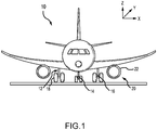
- an aircraft 10 in accordance with various embodiments may include multiple landing gear including a first landing gear 12, a second landing gear 14, and a third landing gear 16.
- the first landing gear 12 and the third landing gear 16 may be main landing gear and the second landing gear 14 may be a nose landing gear.
- Each landing gear may include one or more wheel assemblies.
- the first landing gear 12 includes two wheel assemblies 18. The landing gear 12, 14, 16 and the wheel assemblies 18 support the aircraft 10 in response to the aircraft 10 being parked and during taxi, takeoff, and landing of the aircraft 10.
- the aircraft 10 may further include one or more gas turbine engine 20.
- the gas turbine engine 20 may be controlled by a pilot (such as by controlling a throttle in a cockpit) to generate thrust to accelerate the aircraft 10.
- the gas turbine engine 20 may include a nacelle 22.
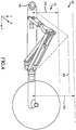
- the landing gear 100 may include a system 101 for supporting the landing gear 100.
- the landing gear 100 may be used as any landing gear such as the landing gear 12, 14, or 16 of FIG. 1 , a nose landing gear, a main landing gear, an auxiliary landing gear, or the like.
- the system 101 may notably facilitate locking of the landing gear 100 in a down and locked position (as shown in FIG. 2 ) and in a stowed position (as shown in FIG. 3 ) without use of an uplock, and with only the drag brace assembly 102 and the jury linkage 114. This desirably reduces complexity and part count of the landing gear 100, also reducing a total weight of the landing gear 100.
- the system 101 further facilitates storage of the landing gear 100 in a relatively small compartment.
- the system 101 may include a drag brace assembly 102 having an upper brace 104 and a lower brace 106.
- the system 101 may further include a jury linkage 114 having a brace portion 116 and a strut portion 118.
- the system 101 may also include a shock strut 126 having an outer cylinder 128 and an inner cylinder 130.
- the upper brace 104 of the drag brace assembly 102 may have an upper end 108 that is designed to be rotatably connected to an aircraft structure.
- the lower brace 106 of the drag brace assembly 102 may have a lower end 110 designed to be rotatably coupled to the shock strut 126.
- the lower end 110 may be rotatably coupled to the outer cylinder 128 of the shock strut 126.
- the upper brace 104 of the drag brace assembly 102 may be pivotally coupled to the lower brace 106 at a center point 112.
- the brace portion 116 of the jury linkage 114 may have a brace end 120 that is pivotally coupled to the drag brace assembly 102.
- the brace end 120 may be pivotally coupled to the center point 112 of the drag brace assembly 102.
- the brace end 120, the upper brace 104, and the lower brace 106 may each be pivotally coupled together at a single location 142.
- the brace end 120, the upper brace 104, and the lower brace 106 may each be pivotally coupled together at the center point 112 using a single pin 144 at the single location 142.
- the single location 142 may be located along a pivot axis A-A'.
- the pivot axis A-A' may be an axis about which the elements may pivot, and may be defined as a single pin 144 axis.
- the strut portion 118 of the jury linkage 114 may have a strut end 122 that is rotatably coupled to the shock strut 126.
- the strut end 122 may be rotatably coupled to the outer cylinder 128 of the shock strut 126.
- the brace portion 116 of the jury linkage 114 and the strut portion 118 of the jury linkage 114 may be pivotally coupled together at a jury center point 124.
- the jury linkage 114 may be referred to as a reshaping jury linkage 114 as it may reform, restructure, or reshape as the landing gear 100 changes states between the down and locked position and the stowed position.
- a length P of the jury linkage 114 may be extended in a straight line in response to the landing gear being in the stowed position, thus locking the landing gear 100 in the stowed position.
- the length P of the jury linkage 114 may be extended in a straight line in response to the landing gear being in the down and locked position, again locking the landing gear 100 in the down and locked position.
- the inner cylinder 130 of the shock strut 126 may be at least partially located within the outer cylinder 128 of the shock strut 126.
- One or more wheel assembly 132 may be coupled to the inner cylinder 130 of the shock strut 126. In response to the wheel assembly 132 contacting a ground surface, the inner cylinder 130 may be further received by the outer cylinder 128 and displacing a fluid, thus providing shock absorption for the landing gear 100.
- the outer cylinder 128 of the shock strut 126 may have a strut attachment 146.
- the strut attachment 146 may be designed to be coupled to a portion of a corresponding aircraft. In various embodiments, the strut attachment 146 may be pivotally coupled to the aircraft.
- an upper drag spindle joint 134 may be located on, or coupled to, the upper end 108 of the drag brace assembly 102.
- the upper drag spindle joint 134 may likewise be coupled to a portion of the aircraft.
- the drag brace assembly 102 may rotate freely relative to the portion of the aircraft to which the upper drag spindle joint 134 is attached.
- a lower drag spindle joint 136 may be located on, or coupled to, the lower end 110 of the drag brace assembly 102.
- the lower drag spindle joint 136 may likewise be coupled to the outer cylinder 128 of the shock strut 126.
- the drag brace assembly 102 may rotate freely relative to the portion of the outer cylinder 128 to which the lower drag spindle joint 136 is attached.
- a jury spindle joint 138 may be located on, or coupled to, the strut end 122 of the jury linkage 114.
- the jury spindle joint 138 may likewise be coupled to the outer cylinder 128 of the shock strut 126.
- the jury linkage 114 may rotate freely relative to the portion of the outer cylinder 128 to which the jury spindle joint 138 is attached.
- FIG. 2 illustrates the landing gear 100 in a down and locked position
- FIG. 3 illustrates the landing gear 100 in a stowed position
- the jury linkage 114 may be positioned in a line (i.e., the brace portion 116 and the strut portion 118 may be aligned along a same axis) in response to the landing gear 100 being in the stowed position and in the down and locked position.
- the jury linkage 114 may be folded (i.e., may form two lines at an angle) during the transition from the stowed position to the down and locked position.
- the drag brace assembly 102 may be positioned in a straight line (i.e., the upper brace 104 and the lower brace 106 may be aligned along a same plane, as defined by the three rotation axes defined by the spindle joints 134, 136, 138) in response to the landing gear 100 being in the down and locked position.
- the drag brace assembly 102 may be angled in response to the landing gear 100 being in the stowed position. In that regard and in response to the drag brace assembly 102 being angled, an angle 140 may exist between the upper brace 104 and the lower brace 106.
- the angle 140 may be less than 180 degrees (i.e., between 0 degrees and 180 degrees), less than 90 degrees (i.e., between 0 and 90 degrees), less than 45 degrees (i.e., between 0 and 45 degrees), or the like.
- the plane of the landing gear 100 shifts as the landing gear 100 is changed between the down and locked position and the stowed position.
- the components of the landing gear 100 are aligned in the Y-Z plane in response to the landing gear being in the down and locked position.
- the plane of the components changes somewhat out of the Y-Z plane such that the components are aligned at least partially in the X-Y plane in response to the landing gear being in the stowed position.
- Such repositioning of the plane is facilitated by the reforming jury linkage 114 along with the rotatable couplings of the various components.
- the landing gear 100 may be stored in a smaller storage compartment (especially along the Z-axis) in response to being stowed than conventional landing gear.
- the system 101 facilitates the landing gear 100 extending for a distance 200 along the Z-axis in response to being in the stowed position.
- conventional landing gear remains along the Y-Z plane in response to being stowed (as shown by a line 204), and thus extends for a distance 202 which is significantly greater than the distance 200 of the landing gear 100.
- references to "one embodiment”, “an embodiment”, “an example embodiment”, etc. indicate that the embodiment described may include a particular feature, structure, or characteristic, but every embodiment may not necessarily include the particular feature, structure, or characteristic. Moreover, such phrases are not necessarily referring to the same embodiment. Further, when a particular feature, structure, or characteristic is described in connection with an embodiment, it is submitted that it is within the knowledge of one skilled in the art to affect such feature, structure, or characteristic in connection with other embodiments whether or not explicitly described. After reading the description, it will be apparent to one skilled in the relevant art(s) how to implement the disclosure in alternative embodiments.
Landscapes
- Engineering & Computer Science (AREA)
- Mechanical Engineering (AREA)
- Aviation & Aerospace Engineering (AREA)
- Fluid-Damping Devices (AREA)
- Vibration Dampers (AREA)
- Transmission Devices (AREA)
- Retarders (AREA)
Applications Claiming Priority (1)
| Application Number | Priority Date | Filing Date | Title |
|---|---|---|---|
| US16/680,285 US11155345B2 (en) | 2019-11-11 | 2019-11-11 | Side folding and reforming linkage for landing gear |
Publications (1)
| Publication Number | Publication Date |
|---|---|
| EP3819210A1 true EP3819210A1 (fr) | 2021-05-12 |
Family
ID=72840388
Family Applications (1)
| Application Number | Title | Priority Date | Filing Date |
|---|---|---|---|
| EP20201349.6A Ceased EP3819210A1 (fr) | 2019-11-11 | 2020-10-12 | Liaison de pliage et de reformage latéral pour train d'atterrissage |
Country Status (3)
| Country | Link |
|---|---|
| US (1) | US11155345B2 (fr) |
| EP (1) | EP3819210A1 (fr) |
| CA (1) | CA3097703A1 (fr) |
Cited By (1)
| Publication number | Priority date | Publication date | Assignee | Title |
|---|---|---|---|---|
| EP3895983A1 (fr) * | 2020-04-17 | 2021-10-20 | Goodrich Corporation | Ensemble trépied de train d'atterrissage |
Citations (7)
| Publication number | Priority date | Publication date | Assignee | Title |
|---|---|---|---|---|
| US3198461A (en) * | 1963-06-20 | 1965-08-03 | Lockheed Aircraft Corp | Retractable landing gear |
| FR2139182A1 (fr) * | 1971-05-26 | 1973-01-05 | British Aircraft Corp Ltd | |
| US5022609A (en) * | 1990-01-10 | 1991-06-11 | Lockheed Corporation | Landing gear |
| US6824100B1 (en) * | 2003-08-15 | 2004-11-30 | The Boeing Company | Airplane landing gear |
| WO2014083170A1 (fr) * | 2012-11-30 | 2014-06-05 | Messier-Bugatti-Dowty | Atterrisseur a contrefiche secondaire a realignement |
| EP3486166A1 (fr) * | 2017-11-15 | 2019-05-22 | Safran Landing Systems | Procédé de manoeuvre d'un atterrisseur d'aéronef entre une position rétractée et une position déployée |
| EP3628592A1 (fr) * | 2018-09-26 | 2020-04-01 | Safran Landing Systems UK Limited | Ensemble de train d'atterrissage d'avion |
Family Cites Families (9)
| Publication number | Priority date | Publication date | Assignee | Title |
|---|---|---|---|---|
| US3951361A (en) | 1975-06-23 | 1976-04-20 | Pneumo Corporation | Articulated main landing gear |
| CA1076090A (fr) | 1977-03-08 | 1980-04-22 | Societe Anonyme Dite: Messier-Hispano-Bugatti | Train d'atterissage escamotable |
| US4132376A (en) * | 1977-09-12 | 1979-01-02 | Lockheed Corporation | Aircraft landing gear torque scissors with universal joint and quick disconnect |
| US4345727A (en) * | 1979-12-26 | 1982-08-24 | The Boeing Company | Body-braced main airplane landing gear |
| FR2805799B1 (fr) * | 2000-03-02 | 2002-06-14 | Messier Dowty Sa | Atterisseur d'aeronef a axe de pivotement de jambe fortement deporte |
| US7066429B2 (en) | 2004-06-25 | 2006-06-27 | The Boeing Company | Apparatus and method for predictable movement of structural components during failure |
| US8070094B2 (en) * | 2008-07-16 | 2011-12-06 | Hamilton Sundstrand Corporation | Aircraft landing gear actuator |
| US8752785B2 (en) | 2012-06-25 | 2014-06-17 | Bell Helicopter Textron Inc. | Semi-levered articulated landing gear system |
| US20150069178A1 (en) * | 2013-09-09 | 2015-03-12 | The Boeing Company | Fuselage-mounted landing gear assembly for use with a low wing aircraft |
-
2019
- 2019-11-11 US US16/680,285 patent/US11155345B2/en active Active
-
2020
- 2020-10-12 EP EP20201349.6A patent/EP3819210A1/fr not_active Ceased
- 2020-10-30 CA CA3097703A patent/CA3097703A1/en active Pending
Patent Citations (7)
| Publication number | Priority date | Publication date | Assignee | Title |
|---|---|---|---|---|
| US3198461A (en) * | 1963-06-20 | 1965-08-03 | Lockheed Aircraft Corp | Retractable landing gear |
| FR2139182A1 (fr) * | 1971-05-26 | 1973-01-05 | British Aircraft Corp Ltd | |
| US5022609A (en) * | 1990-01-10 | 1991-06-11 | Lockheed Corporation | Landing gear |
| US6824100B1 (en) * | 2003-08-15 | 2004-11-30 | The Boeing Company | Airplane landing gear |
| WO2014083170A1 (fr) * | 2012-11-30 | 2014-06-05 | Messier-Bugatti-Dowty | Atterrisseur a contrefiche secondaire a realignement |
| EP3486166A1 (fr) * | 2017-11-15 | 2019-05-22 | Safran Landing Systems | Procédé de manoeuvre d'un atterrisseur d'aéronef entre une position rétractée et une position déployée |
| EP3628592A1 (fr) * | 2018-09-26 | 2020-04-01 | Safran Landing Systems UK Limited | Ensemble de train d'atterrissage d'avion |
Cited By (1)
| Publication number | Priority date | Publication date | Assignee | Title |
|---|---|---|---|---|
| EP3895983A1 (fr) * | 2020-04-17 | 2021-10-20 | Goodrich Corporation | Ensemble trépied de train d'atterrissage |
Also Published As
| Publication number | Publication date |
|---|---|
| US20210139136A1 (en) | 2021-05-13 |
| BR102020022507A8 (pt) | 2024-01-02 |
| US11155345B2 (en) | 2021-10-26 |
| CA3097703A1 (en) | 2021-05-11 |
| BR102020022507A2 (pt) | 2022-02-01 |
Similar Documents
| Publication | Publication Date | Title |
|---|---|---|
| EP3354564B1 (fr) | Train d'atterrissage semi-articulé à essieu unique comportant un mécanisme de raccourcissement | |
| US11235864B2 (en) | Landing gear | |
| US8523107B2 (en) | Fuselage mounted landing gear | |
| US8157206B2 (en) | Two-motion wing-fold mechanism with independent load path | |
| US20120292436A1 (en) | Compact aircraft wing folding systems and methods | |
| US10259568B2 (en) | Non-jamming shrink latch assembly for retractable aircraft landing gear | |
| EP3760537A2 (fr) | Train d'atterrissage | |
| CN113165734B (zh) | 起落架组件 | |
| EP2822853B1 (fr) | Train d'atterrissage monté dans un fuselage | |
| US11084574B2 (en) | Aerodynamic noise reducing thin-skin landing gear structure | |
| EP3895983B1 (fr) | Ensemble trépied de train d'atterrissage | |
| US11155345B2 (en) | Side folding and reforming linkage for landing gear | |
| EP2937281A1 (fr) | Mécanisme d'articulation de poutre de bogie | |
| EP3862263B1 (fr) | Configuration de treillis articulé pour train d'atterrissage d'aéronef | |
| JP2003509275A (ja) | 航空機着陸装置 | |
| US11021239B2 (en) | Shock strut shrinking system | |
| CN205952293U (zh) | 巡航速度范围大的小型长航时无人机 | |
| WO2020256571A1 (fr) | Aéronef à ailes en tandem pliables | |
| EP3941827B1 (fr) | Pales de rotor d'un rotor sustentateur | |
| US10589840B2 (en) | Undercarriage-mounted airfoil | |
| BR102020022507B1 (pt) | Sistema para uso com um trem de pouso de uma aeronave, e, trem de pouso para uso com uma aeronave | |
| CN118205702A (zh) | 一种飞行器用机翼展收装置及飞行器 |
Legal Events
| Date | Code | Title | Description |
|---|---|---|---|
| PUAI | Public reference made under article 153(3) epc to a published international application that has entered the european phase |
Free format text: ORIGINAL CODE: 0009012 |
|
| STAA | Information on the status of an ep patent application or granted ep patent |
Free format text: STATUS: THE APPLICATION HAS BEEN PUBLISHED |
|
| AK | Designated contracting states |
Kind code of ref document: A1 Designated state(s): AL AT BE BG CH CY CZ DE DK EE ES FI FR GB GR HR HU IE IS IT LI LT LU LV MC MK MT NL NO PL PT RO RS SE SI SK SM TR |
|
| STAA | Information on the status of an ep patent application or granted ep patent |
Free format text: STATUS: REQUEST FOR EXAMINATION WAS MADE |
|
| 17P | Request for examination filed |
Effective date: 20211112 |
|
| RBV | Designated contracting states (corrected) |
Designated state(s): AL AT BE BG CH CY CZ DE DK EE ES FI FR GB GR HR HU IE IS IT LI LT LU LV MC MK MT NL NO PL PT RO RS SE SI SK SM TR |
|
| STAA | Information on the status of an ep patent application or granted ep patent |
Free format text: STATUS: EXAMINATION IS IN PROGRESS |
|
| 17Q | First examination report despatched |
Effective date: 20221121 |
|
| P01 | Opt-out of the competence of the unified patent court (upc) registered |
Effective date: 20230922 |
|
| STAA | Information on the status of an ep patent application or granted ep patent |
Free format text: STATUS: THE APPLICATION HAS BEEN REFUSED |
|
| 18R | Application refused |
Effective date: 20251203 |