EP3819253A1 - Enrouleur électro-hydraulique d'une corde sur un tambour d'un treuil et treuil comportant ledit enrouleur - Google Patents
Enrouleur électro-hydraulique d'une corde sur un tambour d'un treuil et treuil comportant ledit enrouleur Download PDFInfo
- Publication number
- EP3819253A1 EP3819253A1 EP20206271.7A EP20206271A EP3819253A1 EP 3819253 A1 EP3819253 A1 EP 3819253A1 EP 20206271 A EP20206271 A EP 20206271A EP 3819253 A1 EP3819253 A1 EP 3819253A1
- Authority
- EP
- European Patent Office
- Prior art keywords
- drum
- winder
- holder
- hydraulic
- winding
- Prior art date
- Legal status (The legal status is an assumption and is not a legal conclusion. Google has not performed a legal analysis and makes no representation as to the accuracy of the status listed.)
- Granted
Links
Images


Classifications
-
- B—PERFORMING OPERATIONS; TRANSPORTING
- B66—HOISTING; LIFTING; HAULING
- B66D—CAPSTANS; WINCHES; TACKLES, e.g. PULLEY BLOCKS; HOISTS
- B66D1/00—Rope, cable, or chain winding mechanisms; Capstans
- B66D1/28—Other constructional details
- B66D1/36—Guiding, or otherwise ensuring winding in an orderly manner, of ropes, cables, or chains
- B66D1/38—Guiding, or otherwise ensuring winding in an orderly manner, of ropes, cables, or chains by means of guides movable relative to drum or barrel
-
- B—PERFORMING OPERATIONS; TRANSPORTING
- B66—HOISTING; LIFTING; HAULING
- B66D—CAPSTANS; WINCHES; TACKLES, e.g. PULLEY BLOCKS; HOISTS
- B66D1/00—Rope, cable, or chain winding mechanisms; Capstans
- B66D1/28—Other constructional details
-
- B—PERFORMING OPERATIONS; TRANSPORTING
- B66—HOISTING; LIFTING; HAULING
- B66D—CAPSTANS; WINCHES; TACKLES, e.g. PULLEY BLOCKS; HOISTS
- B66D1/00—Rope, cable, or chain winding mechanisms; Capstans
- B66D1/28—Other constructional details
- B66D1/40—Control devices
- B66D1/48—Control devices automatic
- B66D1/485—Control devices automatic electrical
Definitions
- the present invention belongs to the field of forestry winches, more precisely to the field of constructional details in forestry winches, which are related to winding of the rope onto a drum of the winch.
- the invention relates to an electro-hydraulic winder for winding a wire rope onto a winch drum and the winch with the said winder.
- the technical problem, which is solved by the present invention, is thus the construction of a system, which will enable uniform winding of the wire rope or the pulling rope onto the winch drum.
- Known mechanical assemblies follow winding of the rope onto the drum and ensure as uniform winding as possible; however, such winding with such assemblies is also prone to deviations, especially in case the winch is tilting and the weight of the winder affects the quality of winding.
- the disadvantage of mechanical winders is also large dimensions, hence such winders are problematic for installation and they are also hard to manufacture as a compact construction.
- Patent US2662703 describes an automatic mechanism for guiding the rope during winding, which is achieved with mechanical components and differs from the present invention in the construction.
- Patent US2424380 discloses a winch with a guide or a winder of a rope, wherein the guide is slidably mounted onto a driven shaft, so that during rotation of the drum during winding, the guide travels in both directions parallel to the drum, resulting in guiding of the rope that is being wound onto the drum.
- This means that the rope is not entangled and is not wound in bunches (more layers of the rope on one side of the drum and less layers or no layers on the other end of the drum).
- the solution according to this document comprises mechanical components, which differs from the present invention. Furthermore, a disadvantage of this solution is that it does not withstand lateral loads.
- Document CN101700859 describes an automatic winder of the rope, which comprises a steel wire rope pulley, a rope releaser sliding block and a winch roller which are sequentially connected by a steel wire rope.
- the multifunctional automatic rope winder has the steel wire rope pulley is placed on a disc rope releaser through a positioning shaft; the rope releaser sliding block is arranged on parallel slideways which are parallel vertically, and a rope release jack and a rope release positioning block are sequentially connected and arranged at one end of the rope releaser sliding block; the rope release jack is communicated with an electric hydraulic pump; and a rope tightening device is arranged in the rope releaser sliding block. Construction of this winder differs from the present invention.
- the essence of the winder for uniform winding of the wire rope onto the drum of the winch is in that it comprises a mechanical assembly of the winder and an electrohydraulic assembly of the winder, which together ensure uniform winding of the wire rope onto the drum, wherein the mechanical assembly senses movement of the wire rope and a tracking system senses coordination of the mechanical assembly and the electrohydraulic assembly, the latter comprising at least a holder with cylinders for guiding the wire rope and a hydraulic cylinder, which controls the said holder, wherein after detected discrepancy the tracking system corrects movement of the holder of the cylinders by controlling the hydraulic cylinder.
- the mechanical assembly of the winder preferably comprises:
- the chain drive may also comprise four sprockets and two chains. It is important the said transmission assembly between the drum and the cross spindle ensures suitable transmission ratio. Consequently, the connection between the cross spindle and the drum may be achieved in any suitable way, not only by using the chain drive. Equally, a belt transmission, a gear transmission or any other transmission can be used in order to transfer rotation movement from the drum onto the spindle.
- the cross spindle is the preferred choice, as during rotation in one direction the nut on the spindle moves left and right, wherein the thread is complete and infinite.
- a thread could be used, but this solution should then also comprise an intermediate gear arranged to switch the rotation direction of the nut.
- a second possible solution is a transversely mounted chain gear with an andle drive from the drum and a hydraulic upgrade. It is also possible to use a linear measuring bar in combination with a sensor the number of drum rotations.
- Movement of the nut left and right precisely mimics the path and the speed of the movement of the wire rope during winding onto the drum.
- the holder with redirecting cylinders is moved, the holder being moved when the drum rotates, so that the rope is being uniformly wound on the drum.
- a suitable valve may also be a mechanical three-way proportional valve installed on the nut of the cross spindle, wherein the controller is not needed.
- the invention could also comprise a steer cylinder without parallelogram mounting, but with the longitudinal guides, which ensure movement of the holder with cylinders.
- the controller of the winch On the nut installed rotational angle sensor, which is connected to the controller of the winch, which measures discrepancy between the position of the nut of the cross spindle and the holder with cylinders (or the path of the hydraulic winder with regards to the path of the nut).
- the controller of the winch based on the measured angle discrepancy and ensures the correction of the path of the hydraulic part of the winder in order to achieve coordinated movement of the nut and the holder with redirecting cylinders and thus also the wire rope.
- the controller performs the correction of the position of the holder with cylinders so that the valve, preferably the three-way electrical proportional valve, is opened, which causes movement of the hydraulic cylinder and consequently the holder with cylinders in the correct direction.
- the winder For operation of the winder it is key to detect the angle and to ensure response from the controller, as even during suitable operation of the winder discrepancies can occur, as the conditions during winding are constantly changing, for example speed of drum rotation due to changes in engine speed, kinematics of the handle mechanism (which does not always ensure uniform movement). In case the correction of the paths of the nut and the holder with cylinders does not occur, the rope is wound onto the drum in an uncontrolled manner, thus resulting in bunches, so that at full load the rope is damaged.
- the winder according to the invention allows setting a range of deviations by correcting the parameters, wherein the ideal angle is near 0°.
- the controller preferably the controller of the winch, continuously tracks data from the sensor.
- the controller senses a discrepancy between the nut of the cross spindle and the holder with cylinders or the handle mechanism
- the controller opens the proportional three-way electrohydraulic valve and thus causes a change of the speed and direction of movement of the hydraulic cylinder.
- the speed of the holder has to increase, which is ensured by the valve which increases the speed of oil flow in the cylinder by opening.
- the parameters of discrepancy and opening of the valve can be changed on the controller, so that optimal operation of the system is achieved.
- the preferred embodiment of the winder is with the angle sensor and the forks on the holder with cylinders, but it could also be replaced with a linear measuring bar or any other element, which can measure or determine the ratio between the nut and the holder with cylinders.
- the purpose of such measuring system in connection with the controller is thus reliable following of the nut of the cross spindle with the holder with cylinders.
- the hydraulic cylinder is the preferred choice, as winches usually have a hydraulic system and because the forces for movement are high. It is also possible to ensure movement with a linear electromotor, but this solution can be too expensive and furthermore needs a source of energy, resulting in a need for additional optimization of the winder and winch construction.
- a second possible embodiment of the winder for uniform winding of the wire rope onto the drum differs from the above-described embodiment only in that instead of controller and angle sensor a mechanical proportional valve is used, the said valve being installed on the nut of the winder, while the handle of the valve is connected to the forks of the holder with cylinders in the same way as in the embodiment described above.
- the winch with the winder according to the invention may be any winch, having one or two drums, wherein the winder enables optimal winding of the rope in uniform layers, due to which the possibility of rope damage.
- the winder is mounted using known means onto the winch on the side, where the wire rope runs towards the drum.
- the winder 1 for uniform winding of the wire rope onto the drum comprises a mechanical assembly 2 and an electrohydraulic assembly 3, which together ensure uniform winding of the rope on the drum 4.
- Figure 1 shows the mechanical assembly 2 of the winder 1 comprising at least:
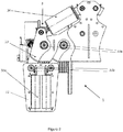
- FIGS 2 and 3 show the preferred embodiment of the winder 1 mechanism with a hydraulic cylinder 34 and the holder 32 of cylinders 32a, which moves when the drum 4 rotates.
- This electrohydraulic assembly 3 of the winder 1 comprises at least:
Landscapes
- Engineering & Computer Science (AREA)
- Mechanical Engineering (AREA)
- Winding Filamentary Materials (AREA)
- Storing, Repeated Paying-Out, And Re-Storing Of Elongated Articles (AREA)
Priority Applications (2)
| Application Number | Priority Date | Filing Date | Title |
|---|---|---|---|
| HRP20250859TT HRP20250859T1 (hr) | 2019-11-06 | 2020-11-06 | Elektrohidraulični koloturnik za sajlu na bubnju vitla i vitlo s navedenim koloturnikom |
| SI202030636T SI3819253T1 (sl) | 2019-11-06 | 2020-11-06 | Elektro-hidravlični navijalec žične vrvi na bobnu vitla in vitel z omenjenim navijalcem |
Applications Claiming Priority (1)
| Application Number | Priority Date | Filing Date | Title |
|---|---|---|---|
| SI201900213A SI25917A (sl) | 2019-11-06 | 2019-11-06 | Elektro-hidravlični navijalec žične vrvi na bobnu vitla in vitel z omenjenim navijalcem |
Publications (2)
| Publication Number | Publication Date |
|---|---|
| EP3819253A1 true EP3819253A1 (fr) | 2021-05-12 |
| EP3819253B1 EP3819253B1 (fr) | 2025-04-30 |
Family
ID=73475853
Family Applications (1)
| Application Number | Title | Priority Date | Filing Date |
|---|---|---|---|
| EP20206271.7A Active EP3819253B1 (fr) | 2019-11-06 | 2020-11-06 | Enrouleur électro-hydraulique d'une corde sur un tambour d'un treuil et treuil comportant ledit enrouleur |
Country Status (4)
| Country | Link |
|---|---|
| EP (1) | EP3819253B1 (fr) |
| HR (1) | HRP20250859T1 (fr) |
| PL (1) | PL3819253T3 (fr) |
| SI (2) | SI25917A (fr) |
Cited By (3)
| Publication number | Priority date | Publication date | Assignee | Title |
|---|---|---|---|---|
| EP4001202A1 (fr) * | 2020-11-11 | 2022-05-25 | Pisek - Vitli Krpan, d.o.o. | Enrouleur électro-hydraulique pour enrouler un câble métallique et treuil avec ledit enrouleur |
| CN114590733A (zh) * | 2022-01-28 | 2022-06-07 | 华电蓝科科技股份有限公司 | 一种卷筒排绳装置及起重机 |
| CN116262598A (zh) * | 2021-12-14 | 2023-06-16 | 中国科学院沈阳自动化研究所 | 一种用于大深度rov收放系统的全自动绞车 |
Citations (7)
| Publication number | Priority date | Publication date | Assignee | Title |
|---|---|---|---|---|
| US2424380A (en) | 1944-11-20 | 1947-07-22 | Jaeger Machine Co | Spooling mechanism for cable winches |
| US2662703A (en) | 1949-12-08 | 1953-12-15 | Howard D Brown | Automatic winch rope winder |
| JPS52105267U (fr) * | 1976-02-06 | 1977-08-10 | ||
| NL8200156A (nl) * | 1982-01-15 | 1983-08-01 | Bezemer Dordrecht B V | Leidinriching voor een kabel. |
| CA1172624A (fr) * | 1981-11-18 | 1984-08-14 | Derek Foster | Guide-fil pour le bobinage |
| CH658041A5 (en) * | 1982-10-27 | 1986-10-15 | Baertschi & Co Ag | Rope winch, in particular for forestry and agriculture |
| CN101700859A (zh) | 2009-11-20 | 2010-05-05 | 兖州煤业股份有限公司 | 多功能绞车自动上绳机 |
-
2019
- 2019-11-06 SI SI201900213A patent/SI25917A/sl active IP Right Grant
-
2020
- 2020-11-06 SI SI202030636T patent/SI3819253T1/sl unknown
- 2020-11-06 PL PL20206271.7T patent/PL3819253T3/pl unknown
- 2020-11-06 HR HRP20250859TT patent/HRP20250859T1/hr unknown
- 2020-11-06 EP EP20206271.7A patent/EP3819253B1/fr active Active
Patent Citations (7)
| Publication number | Priority date | Publication date | Assignee | Title |
|---|---|---|---|---|
| US2424380A (en) | 1944-11-20 | 1947-07-22 | Jaeger Machine Co | Spooling mechanism for cable winches |
| US2662703A (en) | 1949-12-08 | 1953-12-15 | Howard D Brown | Automatic winch rope winder |
| JPS52105267U (fr) * | 1976-02-06 | 1977-08-10 | ||
| CA1172624A (fr) * | 1981-11-18 | 1984-08-14 | Derek Foster | Guide-fil pour le bobinage |
| NL8200156A (nl) * | 1982-01-15 | 1983-08-01 | Bezemer Dordrecht B V | Leidinriching voor een kabel. |
| CH658041A5 (en) * | 1982-10-27 | 1986-10-15 | Baertschi & Co Ag | Rope winch, in particular for forestry and agriculture |
| CN101700859A (zh) | 2009-11-20 | 2010-05-05 | 兖州煤业股份有限公司 | 多功能绞车自动上绳机 |
Cited By (3)
| Publication number | Priority date | Publication date | Assignee | Title |
|---|---|---|---|---|
| EP4001202A1 (fr) * | 2020-11-11 | 2022-05-25 | Pisek - Vitli Krpan, d.o.o. | Enrouleur électro-hydraulique pour enrouler un câble métallique et treuil avec ledit enrouleur |
| CN116262598A (zh) * | 2021-12-14 | 2023-06-16 | 中国科学院沈阳自动化研究所 | 一种用于大深度rov收放系统的全自动绞车 |
| CN114590733A (zh) * | 2022-01-28 | 2022-06-07 | 华电蓝科科技股份有限公司 | 一种卷筒排绳装置及起重机 |
Also Published As
| Publication number | Publication date |
|---|---|
| SI3819253T1 (sl) | 2025-09-30 |
| SI25917A (sl) | 2021-05-31 |
| EP3819253B1 (fr) | 2025-04-30 |
| HRP20250859T1 (hr) | 2025-09-26 |
| PL3819253T3 (pl) | 2025-09-22 |
Similar Documents
| Publication | Publication Date | Title |
|---|---|---|
| EP3819253B1 (fr) | Enrouleur électro-hydraulique d'une corde sur un tambour d'un treuil et treuil comportant ledit enrouleur | |
| US10259677B2 (en) | Automatic cable spooling device | |
| EP1728738B1 (fr) | Système de transport d'articles et procédé d'utilisation du sytème | |
| US4493463A (en) | Cable winding apparatus | |
| CN103562121B (zh) | 双卷筒牵引绞盘 | |
| US20130240809A1 (en) | Cable winch device | |
| CN101837388A (zh) | 焊丝卷取机及送出机 | |
| DK2794459T3 (en) | Drum unit to a well intervention string | |
| CN104144871A (zh) | 绞盘 | |
| US4305513A (en) | Slack cable sensing apparatus | |
| KR20150130268A (ko) | 다-직경 케이블용 케이블 가이드 장치 | |
| CN110683408A (zh) | 基于智能化液压控制技术的卧式高压电缆展放机控制系统 | |
| EP4001202B1 (fr) | Treuil avec un enrouleur électro-hydraulique pour enrouler un câble métallique | |
| JP2014508871A (ja) | ドリルロッドを制御する制御装置 | |
| US10113295B2 (en) | Work machine for dragline bucket operation | |
| NO892838L (no) | Spoleinnretning for tauvinsjer. | |
| CN214866872U (zh) | 一种线缆放线工具 | |
| JP5168557B2 (ja) | フォーク式の物品移載装置 | |
| CN214653254U (zh) | 排缆机构、卷扬装置及作业机械 | |
| CN102733765B (zh) | 建筑装备 | |
| EP4375223A1 (fr) | Dispositif autonome pour enrouler des fils de câble | |
| CA1245203A (fr) | Mecanisme regulateur d'enroulement d'un cable | |
| KR200174611Y1 (ko) | 코크스 오븐용 레벨러의 와이어로프 장력 조절장치 | |
| CN214359954U (zh) | 一种双卷筒智能绞车 | |
| US20240301644A1 (en) | Screen Cleaning Device for Cleaning a Bar Rack of a Screen, and Screen |
Legal Events
| Date | Code | Title | Description |
|---|---|---|---|
| REG | Reference to a national code |
Ref country code: HR Ref legal event code: TUEP Ref document number: P20250859T Country of ref document: HR |
|
| PUAI | Public reference made under article 153(3) epc to a published international application that has entered the european phase |
Free format text: ORIGINAL CODE: 0009012 |
|
| STAA | Information on the status of an ep patent application or granted ep patent |
Free format text: STATUS: THE APPLICATION HAS BEEN PUBLISHED |
|
| AK | Designated contracting states |
Kind code of ref document: A1 Designated state(s): AL AT BE BG CH CY CZ DE DK EE ES FI FR GB GR HR HU IE IS IT LI LT LU LV MC MK MT NL NO PL PT RO RS SE SI SK SM TR |
|
| STAA | Information on the status of an ep patent application or granted ep patent |
Free format text: STATUS: REQUEST FOR EXAMINATION WAS MADE |
|
| 17P | Request for examination filed |
Effective date: 20211108 |
|
| RBV | Designated contracting states (corrected) |
Designated state(s): AL AT BE BG CH CY CZ DE DK EE ES FI FR GB GR HR HU IE IS IT LI LT LU LV MC MK MT NL NO PL PT RO RS SE SI SK SM TR |
|
| STAA | Information on the status of an ep patent application or granted ep patent |
Free format text: STATUS: EXAMINATION IS IN PROGRESS |
|
| 17Q | First examination report despatched |
Effective date: 20230220 |
|
| P01 | Opt-out of the competence of the unified patent court (upc) registered |
Effective date: 20230521 |
|
| TPAC | Observations filed by third parties |
Free format text: ORIGINAL CODE: EPIDOSNTIPA |
|
| GRAP | Despatch of communication of intention to grant a patent |
Free format text: ORIGINAL CODE: EPIDOSNIGR1 |
|
| STAA | Information on the status of an ep patent application or granted ep patent |
Free format text: STATUS: GRANT OF PATENT IS INTENDED |
|
| INTG | Intention to grant announced |
Effective date: 20241203 |
|
| GRAS | Grant fee paid |
Free format text: ORIGINAL CODE: EPIDOSNIGR3 |
|
| GRAA | (expected) grant |
Free format text: ORIGINAL CODE: 0009210 |
|
| STAA | Information on the status of an ep patent application or granted ep patent |
Free format text: STATUS: THE PATENT HAS BEEN GRANTED |
|
| AK | Designated contracting states |
Kind code of ref document: B1 Designated state(s): AL AT BE BG CH CY CZ DE DK EE ES FI FR GB GR HR HU IE IS IT LI LT LU LV MC MK MT NL NO PL PT RO RS SE SI SK SM TR |
|
| REG | Reference to a national code |
Ref country code: CH Ref legal event code: EP Ref country code: GB Ref legal event code: FG4D |
|
| REG | Reference to a national code |
Ref country code: IE Ref legal event code: FG4D |
|
| REG | Reference to a national code |
Ref country code: DE Ref legal event code: R096 Ref document number: 602020050331 Country of ref document: DE |
|
| REG | Reference to a national code |
Ref country code: NL Ref legal event code: MP Effective date: 20250430 |
|
| REG | Reference to a national code |
Ref country code: SK Ref legal event code: T3 Ref document number: E 46744 Country of ref document: SK |
|
| REG | Reference to a national code |
Ref country code: HR Ref legal event code: T1PR Ref document number: P20250859 Country of ref document: HR |
|
| PG25 | Lapsed in a contracting state [announced via postgrant information from national office to epo] |
Ref country code: FI Free format text: LAPSE BECAUSE OF FAILURE TO SUBMIT A TRANSLATION OF THE DESCRIPTION OR TO PAY THE FEE WITHIN THE PRESCRIBED TIME-LIMIT Effective date: 20250430 Ref country code: PT Free format text: LAPSE BECAUSE OF FAILURE TO SUBMIT A TRANSLATION OF THE DESCRIPTION OR TO PAY THE FEE WITHIN THE PRESCRIBED TIME-LIMIT Effective date: 20250901 Ref country code: ES Free format text: LAPSE BECAUSE OF FAILURE TO SUBMIT A TRANSLATION OF THE DESCRIPTION OR TO PAY THE FEE WITHIN THE PRESCRIBED TIME-LIMIT Effective date: 20250430 |
|
| REG | Reference to a national code |
Ref country code: LT Ref legal event code: MG9D |
|
| PG25 | Lapsed in a contracting state [announced via postgrant information from national office to epo] |
Ref country code: GR Free format text: LAPSE BECAUSE OF FAILURE TO SUBMIT A TRANSLATION OF THE DESCRIPTION OR TO PAY THE FEE WITHIN THE PRESCRIBED TIME-LIMIT Effective date: 20250731 Ref country code: NO Free format text: LAPSE BECAUSE OF FAILURE TO SUBMIT A TRANSLATION OF THE DESCRIPTION OR TO PAY THE FEE WITHIN THE PRESCRIBED TIME-LIMIT Effective date: 20250730 |
|
| PG25 | Lapsed in a contracting state [announced via postgrant information from national office to epo] |
Ref country code: NL Free format text: LAPSE BECAUSE OF FAILURE TO SUBMIT A TRANSLATION OF THE DESCRIPTION OR TO PAY THE FEE WITHIN THE PRESCRIBED TIME-LIMIT Effective date: 20250430 |
|
| PG25 | Lapsed in a contracting state [announced via postgrant information from national office to epo] |
Ref country code: BG Free format text: LAPSE BECAUSE OF FAILURE TO SUBMIT A TRANSLATION OF THE DESCRIPTION OR TO PAY THE FEE WITHIN THE PRESCRIBED TIME-LIMIT Effective date: 20250430 |
|
| PG25 | Lapsed in a contracting state [announced via postgrant information from national office to epo] |
Ref country code: RS Free format text: LAPSE BECAUSE OF FAILURE TO SUBMIT A TRANSLATION OF THE DESCRIPTION OR TO PAY THE FEE WITHIN THE PRESCRIBED TIME-LIMIT Effective date: 20250731 |
|
| PG25 | Lapsed in a contracting state [announced via postgrant information from national office to epo] |
Ref country code: IS Free format text: LAPSE BECAUSE OF FAILURE TO SUBMIT A TRANSLATION OF THE DESCRIPTION OR TO PAY THE FEE WITHIN THE PRESCRIBED TIME-LIMIT Effective date: 20250830 |
|
| PG25 | Lapsed in a contracting state [announced via postgrant information from national office to epo] |
Ref country code: LV Free format text: LAPSE BECAUSE OF FAILURE TO SUBMIT A TRANSLATION OF THE DESCRIPTION OR TO PAY THE FEE WITHIN THE PRESCRIBED TIME-LIMIT Effective date: 20250430 |
|
| REG | Reference to a national code |
Ref country code: HR Ref legal event code: ODRP Ref document number: P20250859 Country of ref document: HR Payment date: 20251105 Year of fee payment: 6 |
|
| PGFP | Annual fee paid to national office [announced via postgrant information from national office to epo] |
Ref country code: LU Payment date: 20251105 Year of fee payment: 6 |
|
| PGFP | Annual fee paid to national office [announced via postgrant information from national office to epo] |
Ref country code: DE Payment date: 20251117 Year of fee payment: 6 |
|
| PG25 | Lapsed in a contracting state [announced via postgrant information from national office to epo] |
Ref country code: DK Free format text: LAPSE BECAUSE OF FAILURE TO SUBMIT A TRANSLATION OF THE DESCRIPTION OR TO PAY THE FEE WITHIN THE PRESCRIBED TIME-LIMIT Effective date: 20250430 Ref country code: SM Free format text: LAPSE BECAUSE OF FAILURE TO SUBMIT A TRANSLATION OF THE DESCRIPTION OR TO PAY THE FEE WITHIN THE PRESCRIBED TIME-LIMIT Effective date: 20250430 |
|
| PGFP | Annual fee paid to national office [announced via postgrant information from national office to epo] |
Ref country code: AT Payment date: 20251201 Year of fee payment: 6 |
|
| PGFP | Annual fee paid to national office [announced via postgrant information from national office to epo] |
Ref country code: IT Payment date: 20251125 Year of fee payment: 6 |
|
| PGFP | Annual fee paid to national office [announced via postgrant information from national office to epo] |
Ref country code: HR Payment date: 20251105 Year of fee payment: 6 Ref country code: FR Payment date: 20251127 Year of fee payment: 6 |
|
| PGFP | Annual fee paid to national office [announced via postgrant information from national office to epo] |
Ref country code: CZ Payment date: 20251106 Year of fee payment: 6 |
|
| PGFP | Annual fee paid to national office [announced via postgrant information from national office to epo] |
Ref country code: PL Payment date: 20251106 Year of fee payment: 6 |
|
| PG25 | Lapsed in a contracting state [announced via postgrant information from national office to epo] |
Ref country code: EE Free format text: LAPSE BECAUSE OF FAILURE TO SUBMIT A TRANSLATION OF THE DESCRIPTION OR TO PAY THE FEE WITHIN THE PRESCRIBED TIME-LIMIT Effective date: 20250430 |
|
| PGFP | Annual fee paid to national office [announced via postgrant information from national office to epo] |
Ref country code: SK Payment date: 20251105 Year of fee payment: 6 Ref country code: RO Payment date: 20251105 Year of fee payment: 6 |
|
| PGFP | Annual fee paid to national office [announced via postgrant information from national office to epo] |
Ref country code: SI Payment date: 20251105 Year of fee payment: 6 |
|
| REG | Reference to a national code |
Ref country code: DE Ref legal event code: R097 Ref document number: 602020050331 Country of ref document: DE |
|
| PLBE | No opposition filed within time limit |
Free format text: ORIGINAL CODE: 0009261 |
|
| STAA | Information on the status of an ep patent application or granted ep patent |
Free format text: STATUS: NO OPPOSITION FILED WITHIN TIME LIMIT |
|
| REG | Reference to a national code |
Ref country code: CH Ref legal event code: L10 Free format text: ST27 STATUS EVENT CODE: U-0-0-L10-L00 (AS PROVIDED BY THE NATIONAL OFFICE) Effective date: 20260311 |
|
| 26N | No opposition filed |
Effective date: 20260202 |