EP3819355A1 - Appareil et procédé de lavage de vapeur de produit d'hydrocarbure - Google Patents
Appareil et procédé de lavage de vapeur de produit d'hydrocarbure Download PDFInfo
- Publication number
- EP3819355A1 EP3819355A1 EP20187713.1A EP20187713A EP3819355A1 EP 3819355 A1 EP3819355 A1 EP 3819355A1 EP 20187713 A EP20187713 A EP 20187713A EP 3819355 A1 EP3819355 A1 EP 3819355A1
- Authority
- EP
- European Patent Office
- Prior art keywords
- wash zone
- wash
- vapor
- oil
- zone
- Prior art date
- Legal status (The legal status is an assumption and is not a legal conclusion. Google has not performed a legal analysis and makes no representation as to the accuracy of the status listed.)
- Pending
Links
- 150000002430 hydrocarbons Chemical class 0.000 title claims abstract description 82
- 229930195733 hydrocarbon Natural products 0.000 title claims abstract description 80
- 239000004215 Carbon black (E152) Substances 0.000 title claims abstract description 79
- 238000005406 washing Methods 0.000 title claims abstract description 33
- 238000000034 method Methods 0.000 title claims abstract description 24
- 238000002347 injection Methods 0.000 claims abstract description 50
- 239000007924 injection Substances 0.000 claims abstract description 50
- 239000007921 spray Substances 0.000 claims abstract description 39
- 238000004891 communication Methods 0.000 claims abstract description 14
- 239000012530 fluid Substances 0.000 claims abstract description 13
- 238000005507 spraying Methods 0.000 claims description 3
- 239000003921 oil Substances 0.000 description 74
- 239000000047 product Substances 0.000 description 41
- 238000013461 design Methods 0.000 description 10
- 230000003111 delayed effect Effects 0.000 description 9
- 239000007788 liquid Substances 0.000 description 9
- 238000004939 coking Methods 0.000 description 8
- 239000000571 coke Substances 0.000 description 6
- 238000010276 construction Methods 0.000 description 4
- 230000008901 benefit Effects 0.000 description 3
- 239000002245 particle Substances 0.000 description 3
- 238000010791 quenching Methods 0.000 description 3
- 238000005336 cracking Methods 0.000 description 2
- 239000000463 material Substances 0.000 description 2
- 230000000630 rising effect Effects 0.000 description 2
- 238000000926 separation method Methods 0.000 description 2
- 238000004227 thermal cracking Methods 0.000 description 2
- 239000003795 chemical substances by application Substances 0.000 description 1
- 238000009833 condensation Methods 0.000 description 1
- 230000005494 condensation Effects 0.000 description 1
- 238000011109 contamination Methods 0.000 description 1
- 239000010779 crude oil Substances 0.000 description 1
- 238000004821 distillation Methods 0.000 description 1
- 230000008030 elimination Effects 0.000 description 1
- 238000003379 elimination reaction Methods 0.000 description 1
- 239000012467 final product Substances 0.000 description 1
- 230000005484 gravity Effects 0.000 description 1
- 238000010348 incorporation Methods 0.000 description 1
- 239000002184 metal Substances 0.000 description 1
- 238000012986 modification Methods 0.000 description 1
- 230000004048 modification Effects 0.000 description 1
- 238000012856 packing Methods 0.000 description 1
- 239000002006 petroleum coke Substances 0.000 description 1
- 239000003209 petroleum derivative Substances 0.000 description 1
- 239000007787 solid Substances 0.000 description 1
- 238000012546 transfer Methods 0.000 description 1
- 230000005514 two-phase flow Effects 0.000 description 1
Images




Classifications
-
- C—CHEMISTRY; METALLURGY
- C10—PETROLEUM, GAS OR COKE INDUSTRIES; TECHNICAL GASES CONTAINING CARBON MONOXIDE; FUELS; LUBRICANTS; PEAT
- C10G—CRACKING HYDROCARBON OILS; PRODUCTION OF LIQUID HYDROCARBON MIXTURES, e.g. BY DESTRUCTIVE HYDROGENATION, OLIGOMERISATION, POLYMERISATION; RECOVERY OF HYDROCARBON OILS FROM OIL-SHALE, OIL-SAND, OR GASES; REFINING MIXTURES MAINLY CONSISTING OF HYDROCARBONS; REFORMING OF NAPHTHA; MINERAL WAXES
- C10G21/00—Refining of hydrocarbon oils, in the absence of hydrogen, by extraction with selective solvents
-
- B—PERFORMING OPERATIONS; TRANSPORTING
- B01—PHYSICAL OR CHEMICAL PROCESSES OR APPARATUS IN GENERAL
- B01D—SEPARATION
- B01D47/00—Separating dispersed particles from gases, air or vapours by liquid as separating agent
- B01D47/06—Spray cleaning
- B01D47/063—Spray cleaning with two or more jets impinging against each other
-
- B—PERFORMING OPERATIONS; TRANSPORTING
- B01—PHYSICAL OR CHEMICAL PROCESSES OR APPARATUS IN GENERAL
- B01D—SEPARATION
- B01D47/00—Separating dispersed particles from gases, air or vapours by liquid as separating agent
- B01D47/12—Washers with plural different washing sections
-
- B—PERFORMING OPERATIONS; TRANSPORTING
- B01—PHYSICAL OR CHEMICAL PROCESSES OR APPARATUS IN GENERAL
- B01J—CHEMICAL OR PHYSICAL PROCESSES, e.g. CATALYSIS OR COLLOID CHEMISTRY; THEIR RELEVANT APPARATUS
- B01J19/00—Chemical, physical or physico-chemical processes in general; Their relevant apparatus
-
- B—PERFORMING OPERATIONS; TRANSPORTING
- B01—PHYSICAL OR CHEMICAL PROCESSES OR APPARATUS IN GENERAL
- B01J—CHEMICAL OR PHYSICAL PROCESSES, e.g. CATALYSIS OR COLLOID CHEMISTRY; THEIR RELEVANT APPARATUS
- B01J4/00—Feed or outlet devices; Feed or outlet control devices
- B01J4/001—Feed or outlet devices as such, e.g. feeding tubes
- B01J4/002—Nozzle-type elements
-
- C—CHEMISTRY; METALLURGY
- C10—PETROLEUM, GAS OR COKE INDUSTRIES; TECHNICAL GASES CONTAINING CARBON MONOXIDE; FUELS; LUBRICANTS; PEAT
- C10B—DESTRUCTIVE DISTILLATION OF CARBONACEOUS MATERIALS FOR PRODUCTION OF GAS, COKE, TAR, OR SIMILAR MATERIALS
- C10B55/00—Coking mineral oils, bitumen, tar, and the like or mixtures thereof with solid carbonaceous material
-
- C—CHEMISTRY; METALLURGY
- C10—PETROLEUM, GAS OR COKE INDUSTRIES; TECHNICAL GASES CONTAINING CARBON MONOXIDE; FUELS; LUBRICANTS; PEAT
- C10B—DESTRUCTIVE DISTILLATION OF CARBONACEOUS MATERIALS FOR PRODUCTION OF GAS, COKE, TAR, OR SIMILAR MATERIALS
- C10B57/00—Other carbonising or coking processes; Features of destructive distillation processes in general
- C10B57/04—Other carbonising or coking processes; Features of destructive distillation processes in general using charges of special composition
- C10B57/045—Other carbonising or coking processes; Features of destructive distillation processes in general using charges of special composition containing mineral oils, bitumen, tar or the like or mixtures thereof
-
- C—CHEMISTRY; METALLURGY
- C10—PETROLEUM, GAS OR COKE INDUSTRIES; TECHNICAL GASES CONTAINING CARBON MONOXIDE; FUELS; LUBRICANTS; PEAT
- C10G—CRACKING HYDROCARBON OILS; PRODUCTION OF LIQUID HYDROCARBON MIXTURES, e.g. BY DESTRUCTIVE HYDROGENATION, OLIGOMERISATION, POLYMERISATION; RECOVERY OF HYDROCARBON OILS FROM OIL-SHALE, OIL-SAND, OR GASES; REFINING MIXTURES MAINLY CONSISTING OF HYDROCARBONS; REFORMING OF NAPHTHA; MINERAL WAXES
- C10G9/00—Thermal non-catalytic cracking, in the absence of hydrogen, of hydrocarbon oils
- C10G9/005—Coking (in order to produce liquid products mainly)
-
- C—CHEMISTRY; METALLURGY
- C10—PETROLEUM, GAS OR COKE INDUSTRIES; TECHNICAL GASES CONTAINING CARBON MONOXIDE; FUELS; LUBRICANTS; PEAT
- C10K—PURIFYING OR MODIFYING THE CHEMICAL COMPOSITION OF COMBUSTIBLE GASES CONTAINING CARBON MONOXIDE
- C10K1/00—Purifying combustible gases containing carbon monoxide
- C10K1/08—Purifying combustible gases containing carbon monoxide by washing with liquids; Reviving the used wash liquors
- C10K1/16—Purifying combustible gases containing carbon monoxide by washing with liquids; Reviving the used wash liquors with non-aqueous liquids
- C10K1/18—Purifying combustible gases containing carbon monoxide by washing with liquids; Reviving the used wash liquors with non-aqueous liquids hydrocarbon oils
-
- C—CHEMISTRY; METALLURGY
- C10—PETROLEUM, GAS OR COKE INDUSTRIES; TECHNICAL GASES CONTAINING CARBON MONOXIDE; FUELS; LUBRICANTS; PEAT
- C10G—CRACKING HYDROCARBON OILS; PRODUCTION OF LIQUID HYDROCARBON MIXTURES, e.g. BY DESTRUCTIVE HYDROGENATION, OLIGOMERISATION, POLYMERISATION; RECOVERY OF HYDROCARBON OILS FROM OIL-SHALE, OIL-SAND, OR GASES; REFINING MIXTURES MAINLY CONSISTING OF HYDROCARBONS; REFORMING OF NAPHTHA; MINERAL WAXES
- C10G2300/00—Aspects relating to hydrocarbon processing covered by groups C10G1/00 - C10G99/00
- C10G2300/20—Characteristics of the feedstock or the products
- C10G2300/201—Impurities
- C10G2300/208—Sediments, e.g. bottom sediment and water or BSW
Definitions
- the present disclosure generally relates to delayed coking process.
- the present disclosure relates to an apparatus and a method for washing of product vapor from thermal cracking of heavy hydrocarbon residues.
- Delayed Coking is well known process where a residual oil feed is heated to its thermal cracking temperature in a furnace with multiple parallel passes. During this process, the heavy and long chain hydrocarbon molecules of the residual oil are cracked and converted into coker gas oil and petroleum coke.
- the heavy hydrocarbon residue is preheated and fed into a lower, surge zone at the bottom of the main fractionator. It is further mixed with recycle liquid, which is condensed from product vapor in the fractionator, to define a pool of liquid at the bottom of the fractionator. This process occurs before the reduced crude is rapidly heated and directed to the coke drum for cracking the same into lighter and useful products.
- the fractionator is designed in such a manner that it has various zones for stage wise elimination of the obtained cracked products.
- a wash zone for fractionator column of a delayed coker unit comprises of a trough for collecting the condensed recycle liquid at the bottom of the wash zone and an arrangement of conduits for conveying the recycle liquid, out of contact with the product vapor in the flash zone, from the wash zone to the pool recycle liquid and petroleum residue in the bottom of the fractionator.
- a passage is defined adjacent to the trough to allow the product vapor rising from the flash zone to pass into the wash zone.
- Another known fractionator design consists of a wash zone design wherein a recirculation loop is included in a wash-zone circulation system.
- the vapor product which is routed from the main fractionator column is converted into a two-phase flow by introduction of additional quench flow.
- the recirculation loop bypasses one or more spray headers of the wash zone and returns to a first end of the wash-zone circulation system. Entrained coke particles are filtered and separated out of the re-circulating fluid by filters.
- an existing fractionator wash zone design includes means of addition of an external agent like slop wax.
- the system comprises a feed inlet distributor that reduces the amount of liquid entrained in vapor rising from the feed zone of the distillation column, a wash zone collection apparatus having an improved design for collecting slop wax falling from a liquid/vapor contacting structure provided in the wash zone, a recirculation subsystem for re-circulating at least a portion of the collected slop wax to the top of the wash zone for distribution as wash oil, and a control subsystem.
- the conventional fractionator systems are associated with one or more design problems such as possibility of entrained of coke solids being deposited in wash zone baffles is increased, heavy hydrocarbon material from vapor can ascend to fractionator top section causing fouling in the upper section of fractionator, plugging of the spray header may also occur.
- wax slop as the quench media are generally not possible to design as wax slop availability is very rare. Moreover, wax slop has tendency to get mixed in the wash oil thereby causing contamination in the final product.
- an aspect of the present disclosure is to provide an apparatus for washing hydrocarbon product vapor, where the apparatus comprises of housing, a first wash zone formed within the apparatus at a predefined cross-section of the housing.
- the first wash zone is for receiving the hydrocarbon product vapor coming from the coke drums.
- the first wash zone comprises of a plurality of injection units located near the inner wall of the wash zone at predetermined intervals of the length of the housing corresponding to first wash zone such that the wash oil is injected towards inside of the wash zone.
- the plurality of injection units injects oil droplets formed from the received wash oil within the first wash zone to contact the hydrocarbon product vapor moving upwards through the wash zone.
- a primary washing of the product vapour occurs within the first wash zone.
- the apparatus comprises a second wash zone defined at a predefined cross-section of the housing and located above and in fluid communication with the first wash zone.
- the second wash zone is for receiving the primary washed hydrocarbon vapor coming from the first wash zone and comprises one or more spray headers located horizontally covering a part of the surface area of horizontal plane for receiving wash oil and spraying oil droplets formed from the received wash oil in the vertically downward direction.
- the oil droplets contact the primary washed hydrocarbon vapor exiting the first wash zone and get further washed to produce secondary washed hydrocarbon vapor.
- the heavy refractory hydrocarbon molecules along with asphaltenes are removed further to make clean hydrocarbon product vapour stream for further separation in the upper section of fractionator column.
- Another aspect of the present disclosure is to provide a method of washing of hydrocarbon product vapor coming from delayed coker drums.
- the method comprises of receiving hydrocarbon product vapor coming from delayed coker drums in a first wash zone and further receiving wash oil being supplied from a pump into a plurality of injection units. Further, the method comprises of injecting, oil droplets formed from the received wash oil by the plurality of injection units within the first wash zone to contact the hydrocarbon product vapor thereby, forming a primary washed hydrocarbon vapour in the first wash zone.
- the method comprises receiving the primary washed hydrocarbon vapor from first wash zone by a second wash zone that is located above and in fluid communication with the first wash zone.
- the method comprises of receiving wash oil being supplied from the pump by one or more spray headers and spraying further oil droplets formed from the received wash oil within the second wash zone. Thereafter, the further oil droplets contact the primary washed hydrocarbon vapor and form a secondary washed hydrocarbon vapor in the second wash zone.
- any terms used herein such as but not limited to “includes,” “comprises,” “has,” “consists,” and grammatical variants thereof do NOT specify an exact limitation or restriction and certainly do NOT exclude the possible addition of one or more features or elements, unless otherwise stated, and furthermore must NOT be taken to exclude the possible removal of one or more of the listed features and elements, unless otherwise stated with the limiting language “MUST comprise” or “NEEDS TO include.”
- an apparatus for washing a hydrocarbon product vapor is disclosed.
- Apparatus' as used herein includes a fractionator also known as a fractionating tower to be used in a heavy hydrocarbon cracking process.
- An outlet provided for the present apparatus allows a flow of product obtained in form of cracked hydrocarbon into the delayed coking or coker unit, as known in the art.
- wash oil may be used for washing of hydrocarbon product vapor in the disclosed apparatus.
- the wash oil may include suitable washing mediums known in the art.
- the hydrocarbon product vapor which may be washed in the disclosed apparatus may include an entire range of distilled resids which may include coker naphtha, coker gas oil, Vacuum Gas Oil (VGO), hydrotreated vacuum gas oil (VGO), hydrocracker bottom, straight run naphtha, visbreaker naphtha, vacuum residue (VR), vacuum residue tar (VR tar), reduced crude oil (RCO) and combination thereof.
- VGO Vacuum Gas Oil
- VGO hydrotreated vacuum gas oil
- VR vacuum residue tar
- RCO reduced crude oil
- the hydrocarbon product vapour is washed at different stages within the apparatus.
- the hydrocarbon product vapour is washed in at least two stages. However, more than two stages may be construed from the foregoing description of the washing of the hydrocarbon product vapor with the wash oil within the disclosed apparatus.
- the first stage may include washing of hydrocarbon product vapor when contacted by wash oil being pumped from a pump so as to produce a primary washed hydrocarbon vapor.
- the apparatus as disclosed provides a construction of injection units that facilitates the washing of hydrocarbon product vapor with the wash oil thus enabling the first stage of washing.
- the second stage may include further washing of hydrocarbon product vapor when contacted by wash oil being pumped from a pump so as to produce a secondary washed hydrocarbon vapor.
- the apparatus as disclosed provides a construction of spray headers that facilitates the washing of hydrocarbon product vapor with the wash oil thus enabling the secondary stage of washing.
- the parameters suitable for apparatus may include, but not limited to size of the nozzles or orifices and numbers thereof, wash oil supply pressure, wash oil flow rate. One or more parameters are determined so that the wash oil spray covers the cross section of the apparatus to the optimum.
- injection nozzles or headers can be fixed at desired locations within the apparatus by employing one or more mechanical means including, but not limited to, brackets, bolts.
- the present apparatus and the method efficiently perform washing of hydrocarbon product vapour to remove refractory hydrocarbons and asphaltenes to produce cleaner hydrocarbon product vapor.
- the apparatus as disclosed in the foregoing description enables optimum contact of product vapour with wash oil droplets causing effective washing of the vapour and thereby maintaining improved mass transfer between product vapour and wash oil, reduced coking tendency in the wash zone due to minimum metal surface area.
- present apparatus and method also result in reduced space requirement for wash zone section as the design of the wash zone does not include trays or packing material, therefore, within minimum height of the fractionator column assigned for the wash zone effective washing of the hydrocarbon product vapor takes place.
- the coking tendency in the wash zone also reduces significantly due to the incorporation of design of present invention.
- Figure 1 illustrates a schematic view of an apparatus 100 for washing of hydrocarbon product vapour, in accordance with an embodiment of the present invention.
- the apparatus 100 comprises a housing 102, at least a first wash zone 104, at least a second wash zone 106.
- first wash zone 104 and the second wash zone 106 are described for the purpose of understanding the present invention, it should not be construed as limiting the scope and the apparatus 100 may include more than two wash zones without departing from the scope of the present disclosure. Construction and operational details of the first wash zone 104 and the second wash zone 106 are explained in detail in the subsequent section of the present disclosure.
- the first wash zone 104 is defined by walls of the housing 102 and formed across a predefined cross-section of the housing 102.
- the first wash zone 104 extends in a direction of flow of a primary washed hydrocarbon vapor obtained in the first wash zone 104.
- the first wash zone 104 receives hydrocarbon product vapor entering the apparatus 100 from a supply line that is in operational communication with the apparatus 100.
- the "hydrocarbon product vapor” is hereinafter interchangeably referred to as the "vapor”, without departing from the scope of the present disclosure.
- the vapor moves towards heat shield trays 100-2 located at the bottom of the apparatus 100.
- the vapor moves in an upward direction into the first wash zone 104 along a length L of the housing 102.
- the first wash zone 104 comprises of a plurality of injection units 108 that are located at predetermined intervals of length L corresponding to the first wash zone 104 through the housing 102.
- the predetermined intervals of the length L of location of plurality of injection units 108 may be, but not limiting to, in the range on 1 cm to 100 cm across the first wash zone 104.
- the plurality of injection units 108 receives wash oil as depicted by arrow 100-3 from a pump 110 which is operably connected to the apparatus 100.
- the pump 110 is in fluid communication with the first wash zone 104 and adapted to inject the received wash oil in form of oil droplets 112 within the first wash zone 104.
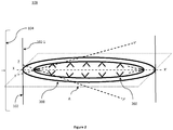
- FIG. 2 illustrates a schematic view of an injecting unit 108 provided in a first wash zone 104 of the apparatus, in accordance with an embodiment of the present disclosure.
- the plurality of injection units 108 which receives the wash oil may comprise of at least one spray ring 200.
- the at least one spray ring 200 may interchangeably be referred to as the spray ring 200.
- the spray ring 200 may be disposed on an inner wall 102-1 of the housing 102 that corresponds to the first wash zone 104.
- the spray ring 200 may include a plurality of injection nozzles 202 for injecting oil droplets 112 within the first wash zone 104.
- the plurality of injection nozzles 202 may be disposed across an inner circumference of the spray ring 200 so that injected oil droplets 112 are dispersed in the entire volume of the first wash zone 104.
- the plurality of injection nozzles 202 may be oriented to inject oil droplets 112 in a horizontal direction parallel to a horizontal plane A of the cross section of the housing 102 corresponding to the first wash zone 104.
- the direction of injection of the oil droplets 112 is as depicted by way of dashed line XX' of the cross-section of the housing 102.
- the plurality of injection nozzles 202 may be oriented to inject oil droplets 112 at an angle of, but not limited to, 30 degrees above with respect to the horizontal plane A of the cross section of the housing 102 corresponding to the first wash zone 104.
- the direction of injection of the oil droplets 112 is depicted by way of dashed line YY'.
- the plurality of injection nozzles 202 may be oriented to inject oil droplets 112 at an angle of, but not limited to, 30 degrees below with respect to the horizontal plane A of the cross section of the housing 102 corresponding to the first wash zone 104.
- the direction of injection of the oil droplets 112 is depicted by way of dotted line ZZ'.
- orientation of the plurality of injection nozzles 202 to inject oil droplets 112 may also be contemplated in each of the orientations depicted by way of dotted lines XX', YY' and ZZ' without departing from the scope of the present invention.
- Figure 3 illustrates a schematic view of another injecting unit 108 provided in the first wash zone 104 of the apparatus 100, in accordance with another embodiment of the present disclosure.
- the plurality of injection units 108 such as a plurality of injections units 308 are in fluid communication with the pump 110 so as to receive the wash oil being supplied from the pump 110 (not shown in figure).
- the plurality of injections units 308 may be disposed across the circumference on the inner wall 102-1 of the housing 102 that corresponds to the first wash zone 104.
- the plurality of injections units 308 are disposed at a predefined vertical elevation on the inner wall 102-1 of the housing 102 that corresponds with the first wash zone 104.
- other arrangements of the plurality of the injection units 308 may also be contemplated without departing from the scope of the present invention.
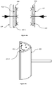
- Figure 4a illustrates a schematic view of another injecting unit 108 provided in the first wash zone 104 of the apparatus 100, in accordance with another embodiment of the present disclosure.
- Figure 4b illustrates a schematic view of a curved rectangular injection header 410 provided in the injecting unit 108of the apparatus 100, in accordance with an embodiment of the present disclosure.
- the plurality of injection units 108 such as a plurality of injection units 408, may be in fluid communication with the pump 110 and receives the wash oil (not shown in the figure).
- Each of the plurality of injection units 408 may comprise of at least one curved rectangular injection header 410.
- the curved rectangular injection header 410 is disposed on the circumference on the inner wall 102-1 of the housing 102 that corresponds to the first wash zone 104. As illustrated in Figure 4b , a plurality of orifices 412 may be disposed on an inner surface 410-1 of the one or more curved rectangular injection header 410. The plurality of orifices 412 is adapted to inject the received wash oil in form of oil droplets 112.
- oil droplets 112 injected from each of the plurality of injection units 108 act as the primary washing media for the hydrocarbon product vapor.
- the oil droplets 112 come in contact and may impinge with the flowing vapor. This may result in the initial break-up of the vapor and thereby, forming a primary washed hydrocarbon vapor.
- this stage may also be referred to as the first stage of washing.
- the second wash zone 106 is located above the first wash zone 104 and configured to be in fluid communication the first wash zone 104.
- the second wash zone 106 is defined by the walls of the housing 102 and formed across a predefined cross-section of the housing 102.
- the second wash zone 106 extends in a direction of flow of a secondary washed hydrocarbon vapor obtained therein.
- the second wash zone 106 receives the primary washed hydrocarbon vapor entering from the first wash zone 104.
- the primary washed hydrocarbon vapor then gradually travels in an upward direction within the second wash zone 106.
- the second wash zone 106 comprises of one or more spray headers 114 that receive wash oil as depicted by arrow 100-3 from the pump 110 which is operably connected to the apparatus 100.
- Each of the spray headers 114 subsequently injects the received wash oil in form of oil droplets 112 within the second wash zone 106.
- the one or more spray headers 114 may spray the oil droplets 112 in a vertically downward direction.
- the one or more spray headers 114 may spray the oil droplets 112 in other possible directions without departing from the scope of the present invention.
- FIG. 5 illustrates a schematic view of the spray header 114 provided in the second wash zone 106 of the apparatus 100, in accordance with an embodiment of the present disclosure.
- each of the spray headers 114 may comprise of at least one main pipe 500 to receive the wash oil being supplied from the pump 110 (not shown in figure).
- the spray header 114 may comprise of a plurality of sub pipes 502 branching out from the main pipe 500 and in fluid communication with the main pipe 500.
- the wash oil flowing in the main pipe 500 gradually enters the plurality of sub pipes 502 and gets distributed in each of the sub pipes 502.
- the main pipe 500 and each of the sub pipes 502 include a plurality of orifices 504 to inject oil droplets 112 formed from the received wash oil.
- each of the plurality of orifices 504 may be disposed, but is not limited to, on a bottom of the main pipe 500 and on a bottom of the plurality of the sub pipes 502 to obtain substantially equal distribution of the oil droplets 112.
- the injected oil droplets 112 from each of one or more spray headers 114 act as the secondary washing media for the vapor.
- the oil droplets 112 come in contact and may impinge with the gradually moving primary washed hydrocarbon vapor. This may result in the further washing of the primary washed hydrocarbon vapor thereby forming a secondary washed hydrocarbon vapor.
- this stage may also be referred to as the second stage of washing.
- FIG. 6 illustrates a flowchart depicting a method 600 for washing the hydrocarbon product vapor using the apparatus 100, in accordance with an embodiment of the present disclosure.
- hydrocarbon product vapor is received by a first wash zone 104 from a supply line 100-1 which is in operational communication with the apparatus 100 as illustrated in Figure 1 .
- the method 600 may include receiving wash oil being supplied from a pump 110, by a plurality of injection units 108. More specifically, the pump 110 is operably connected to the apparatus 100 and in fluid communication with the first wash zone 104 and a second wash zone 106.
- step 606 the received wash oil is injected into the first wash zone 104 in form of oil droplets 112 through the plurality of injection units 108. As illustrated in step 608, the oil droplets 112 come in contact with and impinge the vapor so as to form a primary washed hydrocarbon vapor.
- step 610 the primary washed hydrocarbon vapor then advances to and is received in a second wash zone 106 located above the first wash zone 104. Further, wash oil is introduced in the second wash zone 106 via the pump 110.
- step 612 the wash oil is received by one or more spray headers 114 located within the second wash zone 106.
- each of the spray headers 114 spray oil droplets 112 to contact the advancing primary washed hydrocarbon vapor and thereby, in step 616, forming secondary washed hydrocarbon vapor within the second wash zone 106.
Landscapes
- Chemical & Material Sciences (AREA)
- Oil, Petroleum & Natural Gas (AREA)
- Chemical Kinetics & Catalysis (AREA)
- Engineering & Computer Science (AREA)
- Organic Chemistry (AREA)
- General Chemical & Material Sciences (AREA)
- Physics & Mathematics (AREA)
- Thermal Sciences (AREA)
- Materials Engineering (AREA)
- Combustion & Propulsion (AREA)
- Production Of Liquid Hydrocarbon Mixture For Refining Petroleum (AREA)
- Cleaning By Liquid Or Steam (AREA)
Applications Claiming Priority (1)
| Application Number | Priority Date | Filing Date | Title |
|---|---|---|---|
| IN201921045359 | 2019-11-07 |
Publications (1)
| Publication Number | Publication Date |
|---|---|
| EP3819355A1 true EP3819355A1 (fr) | 2021-05-12 |
Family
ID=71786850
Family Applications (1)
| Application Number | Title | Priority Date | Filing Date |
|---|---|---|---|
| EP20187713.1A Pending EP3819355A1 (fr) | 2019-11-07 | 2020-07-24 | Appareil et procédé de lavage de vapeur de produit d'hydrocarbure |
Country Status (3)
| Country | Link |
|---|---|
| US (1) | US11345862B2 (fr) |
| EP (1) | EP3819355A1 (fr) |
| SA (1) | SA120420023B1 (fr) |
Citations (3)
| Publication number | Priority date | Publication date | Assignee | Title |
|---|---|---|---|---|
| US20100270208A1 (en) * | 2009-04-23 | 2010-10-28 | Conocophillips Company | Efficient method for improved coker gas oil quality |
| CN203923103U (zh) * | 2014-06-24 | 2014-11-05 | 博英睿科(北京)科技有限公司 | 一种具有多洗涤段的延迟焦化洗涤装置 |
| US20160138863A1 (en) * | 2014-11-17 | 2016-05-19 | Nicholas F. Urbanski | Heat Exchange Mechanism For Removing Contaminants From A Hydrocarbon Vapor Stream |
Family Cites Families (9)
| Publication number | Priority date | Publication date | Assignee | Title |
|---|---|---|---|---|
| BE529069A (fr) | ||||
| US2952632A (en) * | 1958-06-16 | 1960-09-13 | Shell Oil Co | Catalytic cracking feed stock preparation |
| US4621724A (en) * | 1984-09-13 | 1986-11-11 | Foster Wheeler Energy Corporation | Fractionator having reduced product vapor condensation in the flash zone |
| US7736470B2 (en) | 2007-01-25 | 2010-06-15 | Exxonmobil Research And Engineering Company | Coker feed method and apparatus |
| US8864951B2 (en) * | 2010-03-19 | 2014-10-21 | ThioSolv, LLC | Systems and processes for improving distillate yield and quality |
| CN204039340U (zh) | 2014-07-11 | 2014-12-24 | 中国石油天然气集团公司 | 一种焦化分馏塔顶循系统 |
| US20160312126A1 (en) | 2015-04-24 | 2016-10-27 | Exxonmobil Research And Engineering Company | Fluid coking process |
| CA3126849C (fr) * | 2017-04-28 | 2023-07-18 | Suncor Energy Inc. | Un module de cokefaction-craquage et procede fonctionnel associe |
| US10786751B2 (en) * | 2018-05-08 | 2020-09-29 | Process Consulting Services, Inc. | Coker fractionator spray wash chamber |
-
2020
- 2020-07-20 US US16/933,554 patent/US11345862B2/en active Active
- 2020-07-24 EP EP20187713.1A patent/EP3819355A1/fr active Pending
- 2020-08-26 SA SA120420023A patent/SA120420023B1/ar unknown
Patent Citations (3)
| Publication number | Priority date | Publication date | Assignee | Title |
|---|---|---|---|---|
| US20100270208A1 (en) * | 2009-04-23 | 2010-10-28 | Conocophillips Company | Efficient method for improved coker gas oil quality |
| CN203923103U (zh) * | 2014-06-24 | 2014-11-05 | 博英睿科(北京)科技有限公司 | 一种具有多洗涤段的延迟焦化洗涤装置 |
| US20160138863A1 (en) * | 2014-11-17 | 2016-05-19 | Nicholas F. Urbanski | Heat Exchange Mechanism For Removing Contaminants From A Hydrocarbon Vapor Stream |
Also Published As
| Publication number | Publication date |
|---|---|
| US11345862B2 (en) | 2022-05-31 |
| US20210139791A1 (en) | 2021-05-13 |
| SA120420023B1 (ar) | 2023-01-19 |
Similar Documents
| Publication | Publication Date | Title |
|---|---|---|
| US11891581B2 (en) | Tower bottoms coke catching device | |
| CN102482586B (zh) | 改善焦化瓦斯油质量的有效方法 | |
| US7427381B2 (en) | Vapor/liquid separation apparatus for use in cracking hydrocarbon feedstock containing resid | |
| US8864951B2 (en) | Systems and processes for improving distillate yield and quality | |
| EP1761615B1 (fr) | Procédé de craquage de charges d'hydrocarbures contenant des résidus et appareil de craquage utilisable à cet effet | |
| US20160216051A1 (en) | Gas distributor for heat exchange and/or mass transfer column | |
| US10786751B2 (en) | Coker fractionator spray wash chamber | |
| EP3551727B1 (fr) | Amélioration de performance de trempe à la vapeur d'eau | |
| US5445799A (en) | Apparatus and method for thermocracking a fluid | |
| US11345862B2 (en) | Apparatus and a method for washing of hydrocarbon product vapor | |
| CN101343553A (zh) | 防止焦炭塔油气出口结焦的装置及其使用方法 | |
| US20200148956A1 (en) | Delayed coker vapor line coke lancing | |
| US11549074B2 (en) | Device comprising lateral injections of liquid for limiting the phenomena of solid deposits in items of equipment with a conical bottom | |
| EP0175523B1 (fr) | Tour de fractionnement à condensation réduite de vapeur dans la zone de vaporisation | |
| JP2010501034A (ja) | 炭化水素質接触分解生成物流の分留方法及び該方法用の分留塔 | |
| US12151189B2 (en) | Primary fractionator with reduced fouling | |
| RU2503707C1 (ru) | Способ и устройство для жидкофазной термической конверсии тяжелого углеводородного сырья | |
| US10676675B2 (en) | Method and hardware for supplying additives to the delayed coker drum |
Legal Events
| Date | Code | Title | Description |
|---|---|---|---|
| PUAI | Public reference made under article 153(3) epc to a published international application that has entered the european phase |
Free format text: ORIGINAL CODE: 0009012 |
|
| STAA | Information on the status of an ep patent application or granted ep patent |
Free format text: STATUS: THE APPLICATION HAS BEEN PUBLISHED |
|
| AK | Designated contracting states |
Kind code of ref document: A1 Designated state(s): AL AT BE BG CH CY CZ DE DK EE ES FI FR GB GR HR HU IE IS IT LI LT LU LV MC MK MT NL NO PL PT RO RS SE SI SK SM TR |
|
| STAA | Information on the status of an ep patent application or granted ep patent |
Free format text: STATUS: REQUEST FOR EXAMINATION WAS MADE |
|
| 17P | Request for examination filed |
Effective date: 20211019 |
|
| RBV | Designated contracting states (corrected) |
Designated state(s): AL AT BE BG CH CY CZ DE DK EE ES FI FR GB GR HR HU IE IS IT LI LT LU LV MC MK MT NL NO PL PT RO RS SE SI SK SM TR |
|
| STAA | Information on the status of an ep patent application or granted ep patent |
Free format text: STATUS: EXAMINATION IS IN PROGRESS |
|
| 17Q | First examination report despatched |
Effective date: 20220203 |
|
| P01 | Opt-out of the competence of the unified patent court (upc) registered |
Effective date: 20230712 |