EP3819509B1 - Roulement à aiguilles à deux rangées comportant un roulement à billes supportant les charges de poussée axiale - Google Patents
Roulement à aiguilles à deux rangées comportant un roulement à billes supportant les charges de poussée axiale Download PDFInfo
- Publication number
- EP3819509B1 EP3819509B1 EP20205817.8A EP20205817A EP3819509B1 EP 3819509 B1 EP3819509 B1 EP 3819509B1 EP 20205817 A EP20205817 A EP 20205817A EP 3819509 B1 EP3819509 B1 EP 3819509B1
- Authority
- EP
- European Patent Office
- Prior art keywords
- race
- roller
- inner ring
- ball
- ring
- Prior art date
- Legal status (The legal status is an assumption and is not a legal conclusion. Google has not performed a legal analysis and makes no representation as to the accuracy of the status listed.)
- Active
Links
Images





Classifications
-
- F—MECHANICAL ENGINEERING; LIGHTING; HEATING; WEAPONS; BLASTING
- F16—ENGINEERING ELEMENTS AND UNITS; GENERAL MEASURES FOR PRODUCING AND MAINTAINING EFFECTIVE FUNCTIONING OF MACHINES OR INSTALLATIONS; THERMAL INSULATION IN GENERAL
- F16C—SHAFTS; FLEXIBLE SHAFTS; ELEMENTS OR CRANKSHAFT MECHANISMS; ROTARY BODIES OTHER THAN GEARING ELEMENTS; BEARINGS
- F16C13/00—Rolls, drums, discs, or the like; Bearings or mountings therefor
- F16C13/006—Guiding rollers, wheels or the like, formed by or on the outer element of a single bearing or bearing unit, e.g. two adjacent bearings, whose ratio of length to diameter is generally less than one
-
- F—MECHANICAL ENGINEERING; LIGHTING; HEATING; WEAPONS; BLASTING
- F16—ENGINEERING ELEMENTS AND UNITS; GENERAL MEASURES FOR PRODUCING AND MAINTAINING EFFECTIVE FUNCTIONING OF MACHINES OR INSTALLATIONS; THERMAL INSULATION IN GENERAL
- F16C—SHAFTS; FLEXIBLE SHAFTS; ELEMENTS OR CRANKSHAFT MECHANISMS; ROTARY BODIES OTHER THAN GEARING ELEMENTS; BEARINGS
- F16C19/00—Bearings with rolling contact, for exclusively rotary movement
- F16C19/22—Bearings with rolling contact, for exclusively rotary movement with bearing rollers essentially of the same size in one or more circular rows, e.g. needle bearings
- F16C19/24—Bearings with rolling contact, for exclusively rotary movement with bearing rollers essentially of the same size in one or more circular rows, e.g. needle bearings for radial load mainly
- F16C19/28—Bearings with rolling contact, for exclusively rotary movement with bearing rollers essentially of the same size in one or more circular rows, e.g. needle bearings for radial load mainly with two or more rows of rollers
-
- F—MECHANICAL ENGINEERING; LIGHTING; HEATING; WEAPONS; BLASTING
- F16—ENGINEERING ELEMENTS AND UNITS; GENERAL MEASURES FOR PRODUCING AND MAINTAINING EFFECTIVE FUNCTIONING OF MACHINES OR INSTALLATIONS; THERMAL INSULATION IN GENERAL
- F16C—SHAFTS; FLEXIBLE SHAFTS; ELEMENTS OR CRANKSHAFT MECHANISMS; ROTARY BODIES OTHER THAN GEARING ELEMENTS; BEARINGS
- F16C19/00—Bearings with rolling contact, for exclusively rotary movement
- F16C19/49—Bearings with both balls and rollers
-
- F—MECHANICAL ENGINEERING; LIGHTING; HEATING; WEAPONS; BLASTING
- F16—ENGINEERING ELEMENTS AND UNITS; GENERAL MEASURES FOR PRODUCING AND MAINTAINING EFFECTIVE FUNCTIONING OF MACHINES OR INSTALLATIONS; THERMAL INSULATION IN GENERAL
- F16C—SHAFTS; FLEXIBLE SHAFTS; ELEMENTS OR CRANKSHAFT MECHANISMS; ROTARY BODIES OTHER THAN GEARING ELEMENTS; BEARINGS
- F16C19/00—Bearings with rolling contact, for exclusively rotary movement
- F16C19/50—Other types of ball or roller bearings
- F16C19/505—Other types of ball or roller bearings with the diameter of the rolling elements of one row differing from the diameter of those of another row
-
- F—MECHANICAL ENGINEERING; LIGHTING; HEATING; WEAPONS; BLASTING
- F16—ENGINEERING ELEMENTS AND UNITS; GENERAL MEASURES FOR PRODUCING AND MAINTAINING EFFECTIVE FUNCTIONING OF MACHINES OR INSTALLATIONS; THERMAL INSULATION IN GENERAL
- F16C—SHAFTS; FLEXIBLE SHAFTS; ELEMENTS OR CRANKSHAFT MECHANISMS; ROTARY BODIES OTHER THAN GEARING ELEMENTS; BEARINGS
- F16C33/00—Parts of bearings; Special methods for making bearings or parts thereof
- F16C33/30—Parts of ball or roller bearings
- F16C33/58—Raceways; Race rings
- F16C33/60—Raceways; Race rings divided or split, e.g. comprising two juxtaposed rings
-
- F—MECHANICAL ENGINEERING; LIGHTING; HEATING; WEAPONS; BLASTING
- F16—ENGINEERING ELEMENTS AND UNITS; GENERAL MEASURES FOR PRODUCING AND MAINTAINING EFFECTIVE FUNCTIONING OF MACHINES OR INSTALLATIONS; THERMAL INSULATION IN GENERAL
- F16C—SHAFTS; FLEXIBLE SHAFTS; ELEMENTS OR CRANKSHAFT MECHANISMS; ROTARY BODIES OTHER THAN GEARING ELEMENTS; BEARINGS
- F16C33/00—Parts of bearings; Special methods for making bearings or parts thereof
- F16C33/30—Parts of ball or roller bearings
- F16C33/66—Special parts or details in view of lubrication
- F16C33/6637—Special parts or details in view of lubrication with liquid lubricant
- F16C33/6659—Details of supply of the liquid to the bearing, e.g. passages or nozzles
- F16C33/6677—Details of supply of the liquid to the bearing, e.g. passages or nozzles from radial inside, e.g. via a passage through the shaft and/or inner ring
-
- F—MECHANICAL ENGINEERING; LIGHTING; HEATING; WEAPONS; BLASTING
- F16—ENGINEERING ELEMENTS AND UNITS; GENERAL MEASURES FOR PRODUCING AND MAINTAINING EFFECTIVE FUNCTIONING OF MACHINES OR INSTALLATIONS; THERMAL INSULATION IN GENERAL
- F16C—SHAFTS; FLEXIBLE SHAFTS; ELEMENTS OR CRANKSHAFT MECHANISMS; ROTARY BODIES OTHER THAN GEARING ELEMENTS; BEARINGS
- F16C33/00—Parts of bearings; Special methods for making bearings or parts thereof
- F16C33/72—Sealings
- F16C33/76—Sealings of ball or roller bearings
- F16C33/78—Sealings of ball or roller bearings with a diaphragm, disc, or ring, with or without resilient members
- F16C33/7836—Sealings of ball or roller bearings with a diaphragm, disc, or ring, with or without resilient members floating with respect to both races
-
- F—MECHANICAL ENGINEERING; LIGHTING; HEATING; WEAPONS; BLASTING
- F16—ENGINEERING ELEMENTS AND UNITS; GENERAL MEASURES FOR PRODUCING AND MAINTAINING EFFECTIVE FUNCTIONING OF MACHINES OR INSTALLATIONS; THERMAL INSULATION IN GENERAL
- F16C—SHAFTS; FLEXIBLE SHAFTS; ELEMENTS OR CRANKSHAFT MECHANISMS; ROTARY BODIES OTHER THAN GEARING ELEMENTS; BEARINGS
- F16C33/00—Parts of bearings; Special methods for making bearings or parts thereof
- F16C33/72—Sealings
- F16C33/76—Sealings of ball or roller bearings
- F16C33/78—Sealings of ball or roller bearings with a diaphragm, disc, or ring, with or without resilient members
- F16C33/784—Sealings of ball or roller bearings with a diaphragm, disc, or ring, with or without resilient members mounted to a groove in the inner surface of the outer race and extending toward the inner race
- F16C33/7843—Sealings of ball or roller bearings with a diaphragm, disc, or ring, with or without resilient members mounted to a groove in the inner surface of the outer race and extending toward the inner race with a single annular sealing disc
-
- F—MECHANICAL ENGINEERING; LIGHTING; HEATING; WEAPONS; BLASTING
- F16—ENGINEERING ELEMENTS AND UNITS; GENERAL MEASURES FOR PRODUCING AND MAINTAINING EFFECTIVE FUNCTIONING OF MACHINES OR INSTALLATIONS; THERMAL INSULATION IN GENERAL
- F16C—SHAFTS; FLEXIBLE SHAFTS; ELEMENTS OR CRANKSHAFT MECHANISMS; ROTARY BODIES OTHER THAN GEARING ELEMENTS; BEARINGS
- F16C2326/00—Articles relating to transporting
- F16C2326/43—Aeroplanes; Helicopters
Definitions
- the present invention relates to an actuation system as indicated in the preamble of claim 1.
- the present disclosure describes a double row needle track roller bearing and more particularly a double row needle track roller bearing that accommodates axial thrust loads with a ball bearing and eliminates the need for re-greasing and re-lubrication.
- Prior art double row needle roller track roller bearings in actuation systems for deploying and retracting a lift assisting device of an edge of a wing of an aircraft have an outer ring and an inner ring with a plurality of needle rollers disposed therebetween and in rolling engagement with bearing surfaces of the inner and outer rings.
- Prior art double row needle roller track roller bearings have no ability to carry axial thrust loads.
- prior art double row needle roller track roller bearings are mounted against bushings and axial ends of the outer ring rotationally rubs against the bushing to carry the axial thrust load.
- a frequent supply of lubricant must be provided to the bushing to mitigate the wear and friction.
- the related patent document EP3176076A1 which discloses the features of the preamble of claim 1, discloses an actuation system for deploying and retracting a lift assisting device of an edge of a wing of an aircraft.
- the actuation system includes a track pivotally coupled to the lift assisting device.
- the track has first and second outer surfaces and side surfaces.
- a shaft is rotationally coupled within the wing of the aircraft and operable, in response to flight control signals, to deploy or retract the lift assisting device.
- Means for actuating the lift assisting device is coupled to the shaft between a retracted position to a deployed position along an arcuate path.
- a plurality of track roller bearings rotatably contact the first and second outer surfaces of the track to guide the track along the arcuate path.
- the plurality of track roller bearings including at least one track roller assembly having a split inner ring and a plurality of rolling elements in rolling engagement with the split inner ring.
- the related patent document DE102010049079 discloses a bearing in which an outer ring has an arcuate track profile and an inner ring has a Gothic track profile.
- the Gothic track profile includes two arc-shaped sections whose centers of curvature are spaced from one another. Balls roll on the outer ring on a raceway. These balls contact the inner ring via two circular arc-shaped sections, which in turn together form the inner ring raceway.
- the related patent document DE102014218047 discloses a combined roller ball bearing with an inner ring and an outer ring, each of which has an associated running groove on which rollers and balls are guided in a cage roll.
- the balls roll in the running grooves and the rollers roll on remaining flat shoulder surfaces of the bearing rings.
- the rollers have a length which is smaller than the width of the remaining shoulder surfaces.
- a row of the rollers is arranged axially on both sides of the row of balls.
- the related patent document US3131006A1 discloses an anti-friction bearing comprising an outer ring formed in a single piece and having an interior roller raceway adjacent each end thereof.
- An interior ball raceway is positioned between the roller raceways.
- An inner ring formed in two sections is arranged in an abutting, end-to-end relation. Each section has an exterior roller raceway with guide flanges and an exterior ball raceway intersecting the abutting faces.
- Cylindrical rollers are positioned in each of the roller raceways.
- Balls are positioned in the ball raceways.
- the several raceways are so proportioned relative to the balls and rollers as to provide a radial clearance between the balls and races which is greater than the radial clearance between the rollers and races.
- the axial clearance between the balls and races is less than the axial clearance between the rollers and races.
- the related patent document JPS5624219 discloses a bearing that can be used for both radial and axial loads.
- the bearing includes outer race means, inner race means, and multiple roller bearings disposed between the outer race means and the inner race means. Seven pairs of annular inner race rings are attached around the bearing support portion of a stud. Each of the inner race rings is composed of an axial portion and a radial portion. A roller for a plurality of roller bearings is installed on a bearing support portion of the stud. A support surface portion is provided for the bearing race means.
- the present invention includes an actuation system for deploying and retracting a lift assisting device of a wing of an aircraft.
- the actuation system includes a track pivotally coupled to the lift assisting device.
- the track has a first outer surface and second a second outer surface opposite the first outer surface.
- a plurality of bearings are disposed in communication (i.e., rolling contact with) with the track.
- Each of the bearings includes a single piece outer ring that includes a radially inward facing first outer roller race, a radially inward facing second outer roller race and a radially inward facing outer ball race.
- the first outer roller race and the second outer roller race and the outer ball race define an interior area of the outer ring.
- Each of the bearings includes an inner ring assembly that includes a first inner ring and a second inner ring that axially abut one another at an abutment interface.
- the first inner ring has a radially outward facing first inner roller race and the second inner ring has a radially outward facing second inner roller race.
- the inner ring assembly is disposed in the interior area coaxially with the outer ring.
- the inner ring has a radially outward facing inner ball race formed in one or both of the first inner ring and the second inner ring.
- a plurality of first rollers each having a first roller diameter and rollingly engage the first outer roller race and the first inner roller race.
- a plurality of second rollers each have a second roller diameter and rollingly engage the second outer roller race and the second inner roller race.
- a plurality of balls each have a ball diameter and a center point. Each of the plurality of balls rollingly engage the outer ball race and the inner ball race.
- the outer ring has an outside surface that rollingly contacts one of the first outer surface and the second outer surface of the track to guide the track along an arcuate path.
- the outer ball race is positioned between the first outer roller race and the second outer roller race; and the inner ball race is positioned between the first inner roller race and the second inner roller race.
- the axial abutment interface is located between axial ends of the inner ball race.
- the ball diameter is less than the first roller diameter and less than the second roller diameter.
- the center point of each of the plurality of balls is aligned with the first inner roller race and the second inner roller race.
- the inner ball race includes a cylindrical segment that is coaxial with a longitudinal axis of the inner ring assembly, extends along a portion of the inner ball race and is located centrally between opposing axial ends of the inner ball race.
- a first seal extends between the inner ring assembly and the outer ring proximate an axial end of the outer ring and a second seal extends between the inner ring assembly and the outer ring proximate an opposing axial end of the outer ring.
- Each of the first seal and the second seal are configured to retain a lubricant between the inner ring assembly during and the outer ring and prior to operational use of the bearing and to retain the inner ring in a predetermined position relative to the outer ring, prior to operational use of the bearing.
- the bearing includes one or more lubrication supply passages (e.g., holes) in the inner ring assembly to supply a lubricant therethrough.
- lubrication supply passages e.g., holes
- the bearing includes one or more barriers for preventing introduction of a lubricant between the inner ring assembly and the outer ring after the bearing is assembled.
- the barrier includes the inner ring assembly, the outer ring, the first seal and the second seal.
- the inner ball race has a first depth and the outer ball race has a second depth.
- the first depth and the second depth each have a magnitude equal to 35 percent to 45 percent of the ball diameter.
- the plurality of balls is a full complement without separators such that each of the plurality of balls touch two adjacent balls.
- an exterior axial surface of the first inner ring and/or the second inner ring extends a standoff distance beyond a respective exterior axial surface of the outer ring and the plurality of balls define an axial play that is less than the standoff distance.
- the bearing is installed in an actuation system for deploying and retracting a lift assisting device of a wing of an aircraft.
- the actuation system includes a track that is pivotally coupled to the lift assisting device.
- the track has a first and second guide surfaces.
- a plurality of the bearings of the present invention rotatably contact the first and second guide surfaces of the track to guide the track along an arcuate path.
- the bearing also includes a lubrication supply passage in the inner ring assembly to supply a lubricant therethrough.
- the outer ball race defines a ball outer diameter and the inner ball race defines an inner ball diameter.
- a radial play of the group of balls is defined as the difference between the ball outer diameter, the inner ball diameter and the two times the ball diameter.
- the outer ball race has a maximum inside diameter and the inner ball race has a minimum outside diameter.
- a radial play of the plurality of balls is defined as the maximum inside diameter minus the minimum outside diameter minus the two times the ball diameter.
- the first plurality of rollers each have a first roller diameter and the second plurality of rollers each have a second roller diameter.
- the first outer roller race defines a first outer roller diameter
- the first inner roller race defines a first inner roller diameter
- the second outer roller race defines a second outer roller diameter
- the second inner roller race defines a second inner roller diameter.
- a first roller radial play is defined as the first outer roller diameter minus the first inner roller diameter d IR1 minus two times the first roller diameter.
- a second roller radial play is defined as the second outer roller diameter minus the second inner roller diameter minus two times the second roller diameter.
- the radial play of the plurality of balls is greater than the first roller radial play and the radial play of the plurality of balls is greater than the second roller radial play.
- the bearing also includes a retention groove defined between the outer ball race and the inner ball race.
- the inner rings and the outer ring are centered on a longitudinal axis.
- a first radial capacity is defined as a total load accommodated by the first group of rollers in a direction perpendicular to the longitudinal axis, between one roller of the first group of rollers, the first inner roller race and the first outer roller race.
- a second radial capacity is defined as a total load accommodated by the second group of rollers in a direction perpendicular to the longitudinal axis, between one roller of the second group of rollers, the second inner roller race and the second outer roller race.
- the group of balls accommodates a load in a direction parallel to the longitudinal axis that is at least 10% of the total of the first radial capacity and the second radial capacity.
- the bearing also includes a retention ring extending between opposing ends of the inner ring and the outer ring.
- Each of the retention rings retains the two piece assembly of the inner ring in a predetermined position relative to the outer ring, prior to use.
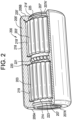
- the bearing used in the present invention is generally designated by the numeral 200.
- the bearing 200 has utility in accommodating axial thrust loads and eliminating the need for relubrication during operation of the bearing 200.
- the bearing 200 has a double channel configuration, as described herein.
- the bearing 200 includes a single piece outer ring 205 that has a radially inward facing first outer roller race 219, a radially inward facing second outer roller race 219' and a radially inward facing outer ball race 222B.
- the outer ball race 222B is positioned between the first outer roller race 219 and the second outer roller race 219'.
- the first outer roller race 219, the second outer roller race 219' and the outer ball race 222B define an interior area of the outer ring 205.
- the bearing 200 includes an inner ring assembly 206 which includes a first inner ring 207 and a second inner ring 207'. Assembly of the bearing 200 is facilitated by the inner ring assembly 206 having the first inner ring 207 and the second inner ring 207'.
- the first inner ring 207 and the second inner ring 207' axially abut one another at an abutment interface, as described further herein.
- the first inner ring 207 has a radially outward facing first inner roller race 214; and the second inner ring 207' has a radially outward facing second inner roller race 214'.
- the inner ring assembly 206 is disposed in the interior area of the outer ring 205, coaxially with the outer ring 205.
- the inner ring assembly 206 includes a radially outward facing inner ball race 222A formed in the first inner ring 207 and the second inner ring 207', as described further herein. While the inner ball race 222A is shown and described as being formed in the first inner ring 207 and the second inner ring 207', the present invention is not limited in this regard, as other configurations may be employed without departing from the broader aspects of the present invention, including but not limited to the inner ball race 222A being formed entirely in the first inner ring 207 or the inner ball race 222A being formed entirely in the second inner ring 207'.
- bearing 200 is shown and described as having a double channel design and having a two piece inner ring assembly 206, the present disclosure is not limited in this regard as other configurations may be employed including but not limited to single channel designs and a one piece inner ring.
- the interior area includes a first cavity 220 located between the first outer roller race 219 and the first inner roller race 214 and a second cavity 220" located between the second outer roller race 219' and the second inner roller race 214.
- the first cavity 220 and the second cavity 220' are initially filled with a lubricant (e.g., grease) during final assembly. After final assembly and during the operating life of the bearing 200, no additional lubricant is supplied to the bearing 200.
- a lubricant e.g., grease
- a plurality of first rollers 203 are disposed in the first cavity 220 between the outer ring 205 and the first inner ring 207 and rollingly engage the first outer roller race 219 and the first inner roller race 214.
- Each of the plurality of first rollers 203 have a first roller diameter D R1 .
- a plurality of second rollers 203' are disposed in the second cavity 220' between the outer ring 205 and the second inner ring 207' and rollingly engage the second outer roller race 219' and the second inner roller race 214'.
- Each of the plurality of second rollers 203' have a second roller diameter D R2 .
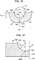
- a plurality of balls 221 are disposed between the outer ring 205 and the inner ring assembly 206. Each of the plurality of balls 221 rollingly engage the outer ball race 222B and the inner ball race 222A. As best shown in FIG. 1E , each of the balls 221 has a ball diameter (D B ) and a center point (CP).
- the outer ball race 222B is positioned between the first outer roller race 219 and the second outer roller race 219'; and the inner ball race 222A is positioned between the first inner roller race 214 and the second inner roller race 214'.
- the first inner ring 207 extends continuously between a first axial end 207A and a second axial end 207B thereof.
- the second inner ring 207' extends continuously between a first axial end 207A' and a second axial end 207B' thereof.
- the first inner roller race 214 extends continuously circumferentially around the first inner ring 207 with no holes or passages extending therethrough.
- the second inner roller race 214' extends continuously circumferentially around the second inner ring 207' with no holes or passages extending therethrough.
- the outer ring 205 has an outer surface 218 (e.g., cylindrical exterior surface) that extends continuously between a first axial end 205A and a second axial end 205B of the outer ring 205.
- the outer surface 218 extends continuously circumferentially around the outer ring 205 with no holes or passages extending therethrough.
- the outer ring 205 includes a first radially inward extending flange 209A located proximate to the first axial end 205A and a second radially inward extending flange 209B located proximate to the second axial end 205B.
- the outer ring 205 has a third radially inward extending flange 209C positioned between (e.g., mid-way between) the first radially inward extending flange 209A and the second radially inward extending flange 209B.
- the outer ball race 222B interrupts (i.e., extends radially and axially outwardly into) a radially inside circumferential surface 205C (see FIG. 1D ) of the third radially inward extending flange 209C.
- the first outer roller race 219 extends between the first radially inward extending flange 209A and the third radially inward extending flange 209C.
- the second outer roller race 219' extends between the second radially inward extending flange 209B and the third radially inward extending flange 209C.
- the abutment interface is located along a reference plane 207X designated by the engagement of the second end axial 207B of the first inner ring 207 and the second axial end 207B' of the second inner ring 207'.
- the abutment interface is located equidistant between axial ends 222AX and 222AY of the inner ball race 222A.
- the ball diameter D B is less than the first roller diameter D R1 (see FIG. 1A ) and less than the second roller diameter D R2 (see FIG. 1A ).
- Each of the plurality of balls 221 has a center point CP that is aligned with the first inner roller race 214 and the second inner roller race 214'.
- having the inner ball race 222A positioned between the first inner roller race 214 and the second inner roller race 214' has utility in making the radial displacement more consistent than other configurations and assists in achieving the radial play P B (see Equation 1, herein) of the plurality of balls 221 to be greater than the first roller radial play P R1 (see Equation 3, herein) and the second roller radial play P R2 (see Equation 4, herein) so that the balls 221 never carry radial load, but only axial load.
- the inner ball race 222A includes a cylindrical segment 222A' that is coaxial with a longitudinal axis C (see FIG. 1A ) of the inner ring assembly 206 (see FIG. 1A ) and extending along a portion of the inner ball race 222A and located centrally between opposing axial ends 222AX and 222AY of the inner ball race 222A.
- a portion of the inner ball race 222A between the axial end 222AX and a first transition point 222AZ1 has a radius RR that extends from a center point RP of the inner ball race 222A of the first inner ring 207.
- the portion of the inner ball race 222A between the axial end 222AX and a first transition point 222AZ1 is circumferential arc segment of a circle having the radius RR.
- a portion of the cylindrical segment 222A' on the first inner ring 207 initiates at the first transition point 222AZ 1 and terminates at the second axial end 207B of the first inner ring 207.
- the first transition point 222AZ1 is spaced apart from the second axial end 207B of the first inner ring 207 by a distance D8.
- the distance D8 is between zero and 3 percent of the radius RR.
- a portion of the inner ball race 222A of the second inner ring 207' is a mirror image of the portion of the inner ball race 222A of the first inner ring 207.
- a portion of the inner ball race 222A between the axial end 222AY and a first transition point 222AZ2 has a radius RR that extends from a center point RR' of the inner ball race 222A of the second inner ring 207'.
- the portion of the inner ball race 222A between the axial end 222AY and a second transition point 222AZ1 is circumferential arc segment of a circle having the radius RR'.
- a portion of the cylindrical segment 222A' on the second inner ring 207' initiates at the second transition point 222AZ2 and terminates at the second axial end 207B' of the second inner ring 207'.
- the second transition point 222AZ2 is spaced apart from the second axial end 207B' of the second inner ring 207' by a distance D8.
- the distance D8 is between zero and 3 percent of the radius RR.
- the first transition point 222AZ1 is spaced apart from the second transition point 222AZ2 such that the cylindrical segment 222A' extends a distance D9 between the first transition point 222AZ1 and the second transition point 222AZ2.
- the distance D9 is about two times the distance D8, namely, between zero and 6 percent of the radius RR or the radius RR'. However, in some embodiments, the distance D8 (and therefore D9) is equal to zero and there is no cylindrical segment 222A', for example see FIG. 1C .
- a ratio of the radius RR of the portion of the inner ball race 222A of the first inner ring 207 to the diameter D B of the ball 221 is about 50.5/100 to 58/100 (i.e., 50.5 to 58 percent). In a preferred embodiment, the ratio of the first inner ring to the diameter D B of the ball 221 is about 53/100 (i.e., 53 percent).
- a first seal 223 extends between the first inner ring 207 and the outer ring 205 proximate to the first axial end 207A of the first inner ring 207 and proximate to the first axial end 205A of the outer ring 205.
- a second seal 225 extends between the second inner ring 207' and the outer ring 205 proximate to the first axial end 207A' of the second inner ring 207' and proximate the second axial end 205B of the outer ring 205.
- Each of the first seal 223 and the second seal 225 retain a lubricant between the inner ring assembly 206 and the outer ring 205.
- the first seal 223 and the second seal 225 also have utility to retain the first inner ring 207 and the second inner ring 207' in predetermined positions relative to the outer ring 205, prior to operational use (e.g., after assembly and during shipping).
- the bearing 200 includes several barriers for preventing the introduction of a lubricant between the inner ring assembly 206 and the outer ring 205 when the bearing 200 is assembled.
- the barriers are defined by the first outer roller race 219; the second outer roller race 219'; the first inner roller race 214'; the second inner roller race 214'; the engagement of the second axial end 207B of the first inner ring 207 and the second axial end 207B' of the second inner ring 207' at the abutment interface; the first seal 223 and the second seal 225.
- the bearing 200 is described as having barriers for preventing the introduction of a lubricant between the inner ring assembly 206 and the outer ring 205, the present invention is not limited in this regard as other configurations may be employed including but not limited to embodiments with a plurality of holes 315 that form lubrication supply passages for supplying lubricant through the first inner ring 207 and a plurality of holes 315' that form lubrication supply passages for supplying lubricant through the second inner ring 207', as shown, for example, in FIG. 4 .
- the first plurality of rollers 203 has a first length L R1 and a first diameter D R1 .
- An aspect ratio of the first length L R1 to the first diameter D R1 of each of the first plurality of rollers 203 is between 3 to 1 and 12 to 1.
- the second plurality of rollers 203' has a second length L R2 and a second diameter D R2 .
- An aspect ratio of the second length L R2 to the first diameter D R2 of each of the second plurality of rollers 203' is between 3 to 1 and 12 to 1.
- the aspect ratio of the first plurality of rollers 203 is approximately 9 to 1 and the aspect ratio of the second plurality of rollers 203' is approximately 9 to 1.
- the inner ball race 222A has a first depth H C1 .
- the outer ball race 222B has a second depth H C2 that extends to a radially inside circumferential surface 205C of the third radially inward extending flange 209C.
- the first depth H C1 and the second depth H C2 each have a magnitude equal to 35 percent to 45 percent of the ball diameter D B .
- each of the plurality of balls 221 is a full complement without separators such that each of the plurality of balls 221 contacts two adjacent balls 221, during use.
- twenty-four balls 221 are arranged between inner ball race 222A and outer ball race 222B. While not limited in this regard, more or fewer than twenty-four balls 221 could be arranged between the inner ball race 222A and the outer ball race 222B.
- the first axial end 207A' of the second inner ring 207' extends a standoff distance D S beyond the second axial end 205B of the outer ring 205.
- the first axial end 207A of the first inner ring 207 has a standoff distance beyond the second axial end 205B of the outer ring 205, similar to that shown in FIG. 1B for the second inner ring 207'.
- the outer ball race 222B has a maximum inside diameter d OB and the inner ball race 222A has a minimum outside diameter d IB .
- a radial play P B (not used in the FIGS. only in the Equation 1) of the plurality of balls 221 is defined the maximum inside diameter d OB minus the minimum outside diameter d IB minus the two times the ball diameter D B .
- the plurality of balls 221 have an axial play P e that is less than the standoff distance D S .
- the first plurality of rollers 203 each have a first roller diameter D R1 and the second plurality of rollers 203' each have a second roller diameter D R2 .
- the first outer roller race 219 defines a first inside diameter d OR1
- the first inner roller race 214 defines a first outside diameter d IR1
- the second outer roller race 219' defines a second inside diameter d OR2
- the second inner roller race 214' defines a second outside diameter d IR2 .
- a first roller radial play P R1 is defined as the first inside diameter d OR1 minus the first outside diameter d IR1 minus two times the first roller diameter D R1 .
- a second roller radial play P R2 is defined as the second inside diameter d OR2 minus the second outside diameter d IR2 minus two times the second roller diameter D R2 .
- the radial play P B of the plurality of balls 221 is greater than the first roller radial play P R1 and the radial play P B of the plurality of balls 221 is greater than the second roller radial play P R2 .
- the first plurality of rollers 203 and/or the second plurality of rollers 203' accommodate radial loads between the outer ring 205 and the inner rings 207, 207' and the plurality of balls 221 do not accommodate any significant radial loads.
- the plurality of balls 221 do accommodate axial loads.
- a first radial capacity is defined as a total load accommodated by the first plurality of rollers 203, exerted in a direction perpendicular to the longitudinal axis C, between one of the first plurality of rollers 203, the first inner roller race 214 and the first outer roller race 219.
- a second radial capacity is defined as a total load accommodated by the second plurality of rollers 203', exerted in a direction perpendicular to the longitudinal axis C, between one of the second plurality of rollers 203', the second inner roller race 214' and the second outer roller race 219'.
- the plurality of balls 221 accommodate an axial load, exerted in a direction parallel to the longitudinal axis C, that is at least 10 percent of the total of the first radial capacity or at least 10 percent of the second radial capacity.
- a retention ring extends between opposing ends of the inner ring assembly 206 and the outer ring 205 to retain the two piece assembly of the inner ring assembly 206 in a predetermined position relative to the outer ring 205, prior to use.
- the outer ring 205, the first inner ring 207, the second inner ring 207', the first pluralities of rollers 203, the second plurality of rollers 203', and the plurality of balls 221 of the bearing 200 are manufactured from a hardened stainless steel such as, for example, 440C, 52100, 422 stainless with a special nitriding process (AeroCres ® )(AEROCRES is registered trademark of RBC Aircraft Products, Inc., Oxford, Connecticut USA), XD-15NW, and Cronidur 30.
- a hardened stainless steel such as, for example, 440C, 52100, 422 stainless with a special nitriding process (AeroCres ® )(AEROCRES is registered trademark of RBC Aircraft Products, Inc., Oxford, Connecticut USA), XD-15NW, and Cronidur 30.
- FIG. 5 provides a plan view of a leading edge section 12 of a wing of an aircraft.
- the wing 10 includes a plurality of slat panels 20 deployed along the leading edge 12 of the wing 10.
- the actuation system 40 selectively extends and retracts the slat panels 20 relative to the leading edge 12 in response to flight control signals, as is generally known in the art.
- four of the bearings 200 of the present invention are coupled to a mounting web 110 about a first outer surface 56 and a second outer surface 58 of a track 50 to support and guide the track 50 during deployment and retraction of the track 50.
- the track 50 track is pivotally coupled to the lift assisting device and extends along an arcuate path A from a rear portion 52 to a forward portion 54.
- the outer surface 218 of the outer ring 205 of each bearing 200 rollingly contacts either the first outer surface 56 or the second outer surface 58 of the track 50 to guide the track 50 along the arcuate path A.
- the slat panel 20 In the retracted position 20' (e.g., flight position) the slat panel 20 is located against the leading edge 12 of the wing 10 and in the deployed position 20" (e.g., take-off and landing position) the slat panel 20 is deployed downwardly and forwardly away from the leading edge portion 12 of the wing 10 (see arrow B), thus increasing a surface area of the wing 10 to vary the wing's liftenhancing characteristics.
- the deployed position 20" e.g., take-off and landing position
Landscapes
- Engineering & Computer Science (AREA)
- General Engineering & Computer Science (AREA)
- Mechanical Engineering (AREA)
- Rolling Contact Bearings (AREA)
Claims (11)
- Système d'actionnement (40) pour sortir et rentrer un dispositif d'aide à la portance d'une aile (10) d'un aéronef (8), le système d'actionnement (40) comprenant :un rail (50) accouplé pivotant au dispositif d'aide à la portance, le rail (50) étant pourvu d'une première surface extérieure (56) et d'une deuxième surface extérieure (58) opposée à la première surface extérieure (56) ;une pluralité de roulements (200) comprenant chacun :une bague extérieure monobloc (205) comprenant un premier chemin de roulement de rouleaux extérieur (219) orienté radialement vers l'intérieur et un deuxième chemin de roulement de rouleaux extérieur (219') orienté radialement vers l'intérieur ;un ensemble de bagues intérieures (206) comprenant une première bague intérieure (207) et une deuxième bague intérieure (207') venant axialement en butée l'une contre l'autre au niveau d'une interface de butée, la première bague intérieure (207) étant pourvue d'un premier chemin de roulement de rouleaux intérieur (214) orienté radialement vers l'extérieur, la deuxième bague intérieure étant pourvue d'un deuxième chemin de roulement de rouleaux intérieur (214') orienté radialement vers l'extérieur, l'ensemble de bagues intérieures (206) étant agencé dans la région intérieure coaxialement avec la bague extérieure (205) ;une pluralité de premiers rouleaux (203) pourvus chacun d'un premier diamètre de rouleau (DR1) et chacun de la pluralité de premiers rouleaux (203) s'engageant en roulant sur le premier chemin de roulement de rouleaux extérieur (219) et le premier chemin de roulement de rouleaux intérieur (214) ; etune pluralité de deuxièmes rouleaux (203') pourvus chacun d'un deuxième diamètre de rouleau (DR2) et chacun de la pluralité de deuxièmes rouleaux (203') s'engageant en roulant sur le deuxième chemin de roulement de rouleaux extérieur (219') et le deuxième chemin de roulement de rouleaux intérieur (214') ;la bague extérieure (205) étant pourvue d'une surface extérieure (218) venant en contact roulant avec l'une parmi la première surface extérieure (56) et de la deuxième surface extérieure (58) du rail (50) pour guider le rail (50) le long d'une trajectoire courbe (A), caractérisé en ce que la bague extérieure monobloc (205) comprend en outre et un chemin de roulement de billes extérieur (222B) orienté radialement vers l'intérieur, le premier chemin de roulement de rouleaux extérieur (219), le deuxième chemin de roulement de rouleaux extérieur (219') et le chemin de roulement de billes extérieur (222B) délimitant une zone intérieure de la bague extérieure (205),l'ensemble de bagues intérieures (206) comprend en outre un chemin de roulement de billes intérieur (222A) orienté radialement vers l'extérieur ménagé dans au moins une parmi la première bague intérieure (207) et la deuxième bague intérieure (207'), eten ce que le système d'actionnement (40) comprend en outre une pluralité de billes (221) pourvues chacune d'un diamètre de bille (DB) et d'un point central (CP), chacune de la pluralité de billes s'engageant en roulant sur le chemin de roulement de billes extérieur (222B) et le chemin de roulement de billes intérieur (222A).
- Système d'actionnement selon la revendication 1, dans lequel le chemin de roulement de billes extérieur (222B) est positionné entre le premier chemin de roulement de rouleaux extérieur (219) et le deuxième chemin de roulement de rouleaux extérieur (219'), et dans lequel le chemin de roulement de billes intérieur (222A) est positionné entre le premier chemin de roulement de rouleaux intérieur (214) et le deuxième chemin de roulement de rouleaux intérieur (214').
- Système d'actionnement selon l'une quelconque des revendications 1 à 2, dans lequel :l'interface de butée est située entre des extrémités axiales du chemin de roulement de billes intérieur (222A) ; et/oule diamètre de bille (DB) est inférieur au premier diamètre de rouleau (DR1) et inférieur au deuxième diamètre de rouleau (DR2) ; et/oule point central (CP) est aligné avec le premier chemin de roulement de rouleaux intérieur (214) et le deuxième chemin de roulement de rouleaux intérieur (214').
- Système d'actionnement selon l'une quelconque des revendications 1 à 3, dans lequel le chemin de roulement de billes intérieur (222A) comprend un segment cylindrique (222A') coaxial avec un axe longitudinal (C) de l'ensemble de bagues intérieures (206) et s'étendant le long d'une partie du chemin de roulement de billes intérieur (222A) et centré entre des extrémités axiales opposées (222AX et 222AY) du chemin de roulement de billes intérieur (222A).
- Système d'actionnement selon l'une quelconque des revendications précédentes, comprenant en outre un premier joint d'étanchéité (223) s'étendant entre l'ensemble de bagues intérieures (206) et la bague extérieure (205) à proximité d'une extrémité axiale (205A) de la bague extérieure (205) et un deuxième joint d'étanchéité (225) s'étendant entre l'ensemble de bague intérieures (206) et la bague extérieure (205) à proximité d'une extrémité axiale opposée (205B) de la bague extérieure (205), chacun parmi le premier joint d'étanchéité (223) et le deuxième joint d'étanchéité (225) étant configuré pour maintenir un lubrifiant entre l'ensemble de bagues intérieures (206) et la bague extérieure (205) avant et pendant l'utilisation en service du roulement (200), pour maintenir l'ensemble de bagues intérieures (206) dans une position prédéterminée par rapport à la bague extérieure (205), avant l'utilisation en service du roulement (200).
- Système d'actionnement selon l'une quelconque des revendications précédentes, comprenant en outre au moins un passage d'amenée de lubrifiant (315, 315') dans la bague intérieure (207) pour amener un lubrifiant à travers elle.
- Système d'actionnement selon la revendication 5, comprenant en outre :au moins une barrière pour empêcher l'introduction d'un lubrifiant entre l'ensemble de bagues intérieures (206) et la bague extérieure (205) après l'assemblage du roulement (200) ; et/ouau moins une barrière pour empêcher l'introduction du lubrifiant entre l'ensemble de bagues intérieures (206) et la bague extérieure (205) après l'assemblage du roulement (200), l'au moins une barrière comprenant l'ensemble de bagues intérieures (206), la bague extérieure (205), le premier joint d'étanchéité (223) et le deuxième joint d'étanchéité (225).
- Système d'actionnement selon l'une quelconque des revendications précédentes, dans lequel chacun de la pluralité de premiers rouleaux (203) est pourvu d'une première longueur axiale (LR1) et dans lequel un rapport d'aspect de la première longueur (LR1) sur le premier diamètre (DR1) est compris entre 3 sur 1 et 12 sur 1.
- Système d'actionnement selon l'une quelconque des revendications précédentes, dans lequel le chemin de roulement de billes intérieur (222A) est pourvu d'une première profondeur (HC1) et le chemin de roulement de billes extérieur (222B) est pourvu d'une deuxième profondeur (HC2), la première profondeur (HC1) et la deuxième profondeur (HC2) ayant chacune une grandeur égale à entre 35 pour cent et 45 pour cent du diamètre de bille (DB).
- Système d'actionnement selon l'une quelconque des revendications précédentes, dans lequel la pluralité de billes (221) constitue un ensemble complet sans séparateurs de sorte que chacune de la pluralité de billes (221) touche deux billes adjacentes (221).
- Système d'actionnement selon l'une quelconque des revendications précédentes, dans lequel une surface axiale extérieure (207A, 207A') d'au moins une parmi la première bague intérieure (207) et la deuxième bague intérieure (207') s'étend sur une distance de garde (Ds) au-delà d'une surface axiale extérieure respective (205A, 205B) de la bague extérieure (205),la pluralité de billes (221) définissant un jeu axial (Pe,) ; etle jeu axial (Pe) étant inférieur à la distance de garde (Ds).
Priority Applications (1)
| Application Number | Priority Date | Filing Date | Title |
|---|---|---|---|
| EP22180779.5A EP4083455A1 (fr) | 2019-11-05 | 2020-11-05 | Roulement à rouleaux de tracé d'aiguille à deux rangées comportant un roulement à billes porteur de charge de poussée |
Applications Claiming Priority (1)
| Application Number | Priority Date | Filing Date | Title |
|---|---|---|---|
| US201962930666P | 2019-11-05 | 2019-11-05 |
Related Child Applications (2)
| Application Number | Title | Priority Date | Filing Date |
|---|---|---|---|
| EP22180779.5A Division-Into EP4083455A1 (fr) | 2019-11-05 | 2020-11-05 | Roulement à rouleaux de tracé d'aiguille à deux rangées comportant un roulement à billes porteur de charge de poussée |
| EP22180779.5A Division EP4083455A1 (fr) | 2019-11-05 | 2020-11-05 | Roulement à rouleaux de tracé d'aiguille à deux rangées comportant un roulement à billes porteur de charge de poussée |
Publications (2)
| Publication Number | Publication Date |
|---|---|
| EP3819509A1 EP3819509A1 (fr) | 2021-05-12 |
| EP3819509B1 true EP3819509B1 (fr) | 2023-03-08 |
Family
ID=73138632
Family Applications (2)
| Application Number | Title | Priority Date | Filing Date |
|---|---|---|---|
| EP22180779.5A Withdrawn EP4083455A1 (fr) | 2019-11-05 | 2020-11-05 | Roulement à rouleaux de tracé d'aiguille à deux rangées comportant un roulement à billes porteur de charge de poussée |
| EP20205817.8A Active EP3819509B1 (fr) | 2019-11-05 | 2020-11-05 | Roulement à aiguilles à deux rangées comportant un roulement à billes supportant les charges de poussée axiale |
Family Applications Before (1)
| Application Number | Title | Priority Date | Filing Date |
|---|---|---|---|
| EP22180779.5A Withdrawn EP4083455A1 (fr) | 2019-11-05 | 2020-11-05 | Roulement à rouleaux de tracé d'aiguille à deux rangées comportant un roulement à billes porteur de charge de poussée |
Country Status (2)
| Country | Link |
|---|---|
| US (1) | US11274699B2 (fr) |
| EP (2) | EP4083455A1 (fr) |
Family Cites Families (33)
| Publication number | Priority date | Publication date | Assignee | Title |
|---|---|---|---|---|
| US2040489A (en) | 1933-12-14 | 1936-05-12 | Gen Motors Corp | Antifriction bearing |
| US1972140A (en) | 1934-01-17 | 1934-09-04 | Timken Roller Bearing Co | Roller bearing |
| US2470071A (en) | 1945-05-07 | 1949-05-10 | Norma Hoffmann Bearings Corp | Axle box |
| US2915346A (en) | 1956-05-09 | 1959-12-01 | Ralph F Stallman | Roller bearing assembly for track layer rollers |
| DE1185867B (de) | 1960-01-04 | 1965-01-21 | Schaeffler Ohg Industriewerk | An beiden Enden einstueckig mit Borden versehener geteilter Laufring eines mehrreihigen Zylinderrollenlagers |
| US3131006A (en) | 1961-09-13 | 1964-04-28 | American Brake Shoe Co | Journal bearing |
| US3155006A (en) | 1962-06-18 | 1964-11-03 | Cincinnati Milling Machine Co | Arbor support bushing for a machine tool |
| US3167363A (en) | 1962-12-17 | 1965-01-26 | Torrington Co | Combined radial and thrust bearing |
| US3424507A (en) | 1966-08-02 | 1969-01-28 | Torrington Co | Water pump bearing |
| JPS52148184A (en) | 1976-05-07 | 1977-12-09 | Hitachi Chemical Co Ltd | Method and device for testing life of pipe |
| DE2907342A1 (de) | 1979-02-24 | 1980-09-04 | Kugelfischer G Schaefer & Co | Radial-axial-lagerung |
| JPS5624219A (en) * | 1979-08-01 | 1981-03-07 | Accurate Bushing Co | Bearing loaded radial and axial force |
| EP0774760B1 (fr) | 1995-11-20 | 2000-08-23 | General Electric Company | Système pour changer des dispositifs d'entraínement de barre de contrôle d'un réacteur nucléaire |
| DE10061786B4 (de) * | 2000-12-12 | 2015-12-03 | Schaeffler Technologies AG & Co. KG | Stützrollenlager als gedichtete Baueinheit |
| JP3707553B2 (ja) | 2001-08-01 | 2005-10-19 | 日本精工株式会社 | 工作機械用アンギュラ玉軸受 |
| CN2703158Y (zh) * | 2004-06-07 | 2005-06-01 | 郭满生 | 大型组合轴承 |
| DE102006020412A1 (de) | 2006-05-03 | 2007-11-08 | Schaeffler Kg | Wälzlager einer Wasserpumpe eines Verbrennungsmotors |
| WO2008055747A1 (fr) | 2006-11-08 | 2008-05-15 | Schaeffler Kg | Disposition de palier d'un arbre |
| DE102009035750A1 (de) | 2009-08-01 | 2011-02-03 | Schaeffler Technologies Gmbh & Co. Kg | Einlagerkonstruktion sowie Windkraftanlage mit der Einlagerkonstruktion |
| DE102010038305B4 (de) | 2010-07-23 | 2019-09-05 | Aktiebolaget Skf | Wälzlageranordnung mit einer Haltevorrichtung |
| WO2012014634A1 (fr) | 2010-07-30 | 2012-02-02 | Ntn株式会社 | Différentiel réducteur pour véhicule électrique |
| DE102010049079A1 (de) * | 2010-10-20 | 2012-04-26 | Schaeffler Technologies Gmbh & Co. Kg | Lageranordnung |
| EP2642145A4 (fr) | 2010-11-16 | 2015-10-21 | Ntn Toyo Bearing Co Ltd | Roulement à billes, et procédé de production de roulement à billes |
| US9500231B2 (en) * | 2011-09-30 | 2016-11-22 | Williams International Co., L.L.C. | Fractured-outer-race full-complement ball-bearing system incorporated in a turbocharger assembly |
| WO2015139108A1 (fr) | 2014-03-21 | 2015-09-24 | Halliburton Energy Services, Inc. | Appareil avec ensemble joint d'étanchéité rotatif coïncidant axialement avec un point focal d'inclinaison d'arbre |
| CN105089967B (zh) | 2014-05-21 | 2018-04-20 | 比泽尔制冷技术(中国)有限公司 | 双向摇盘压缩机 |
| DE102014218047A1 (de) * | 2014-09-10 | 2016-03-10 | Schaeffler Technologies AG & Co. KG | Kombiniertes Rollen-Kugellager |
| CN104675951B (zh) | 2015-02-11 | 2017-02-01 | 吉林大学 | 带有双排行星齿轮转矩定向分配机构的电动差速器 |
| US20170089218A1 (en) | 2015-09-25 | 2017-03-30 | General Electric Company | Double row cylindrical roller bearing with high length to diameter ratio rollers |
| EP3527488B1 (fr) * | 2015-12-04 | 2021-03-03 | Roller Bearing Company of America, Inc. | Chemin de roulement interne et externe singulaire sur roulement à éléments roulants |
| EP3388702B1 (fr) * | 2017-04-13 | 2020-06-03 | Roller Bearing Company of America, Inc. | Ensemble d'étanchéité en deux parties pour un palier de galet de roulement |
| DE102018206635A1 (de) | 2017-12-20 | 2019-06-27 | Aktiebolaget Skf | Hybridwälzlager insbesondere für einen Kühlkompressor |
| DE102018125866B3 (de) | 2018-10-18 | 2019-06-27 | Schaeffler Technologies AG & Co. KG | Unwuchtwelle |
-
2020
- 2020-11-05 EP EP22180779.5A patent/EP4083455A1/fr not_active Withdrawn
- 2020-11-05 EP EP20205817.8A patent/EP3819509B1/fr active Active
- 2020-11-05 US US17/090,521 patent/US11274699B2/en not_active Expired - Fee Related
Also Published As
| Publication number | Publication date |
|---|---|
| US11274699B2 (en) | 2022-03-15 |
| EP3819509A1 (fr) | 2021-05-12 |
| EP4083455A1 (fr) | 2022-11-02 |
| US20210131491A1 (en) | 2021-05-06 |
Similar Documents
| Publication | Publication Date | Title |
|---|---|---|
| DE4448040B4 (de) | Selbstausrichtendes Rollenlager mit Käfig | |
| EP0595519B1 (fr) | Support de palier chargé de ressorts | |
| US6367982B1 (en) | Cylindrical roller bearing | |
| CZ20004319A3 (en) | Rolling-contact bearing | |
| EP1853829A1 (fr) | Roulement libre haute vitesse destine, en particulier, a loger la broche principale d'une machine-outil | |
| GB2311568A (en) | Angular roller bearing assembly | |
| EP3819509B1 (fr) | Roulement à aiguilles à deux rangées comportant un roulement à billes supportant les charges de poussée axiale | |
| US4714359A (en) | Rolling bearing arrangement, in particular for work rolls in high-speed rolling mills | |
| EP0353407B1 (fr) | Cage à doigts de séparation pour roulement à rouleaux de grande dimension | |
| DE10327641B4 (de) | Segmentlager zur radialen und axialen Lagerung eines Schlittenteils an einem Führungsteil | |
| JP3584040B2 (ja) | ころに正のスキュー角を与える手段を有するころ軸受 | |
| WO2008071735A2 (fr) | Palier de réglage | |
| CN114198399A (zh) | 用于滚动轴承、尤其是大直径滚动轴承的保持架分段 | |
| IE48841B1 (en) | A roller drill bit | |
| JPS61171917A (ja) | 圧延機ロールネック用多列ころ軸受 | |
| EP2431623A2 (fr) | Palier de rouleau toroïdal | |
| US20220235821A1 (en) | Cage segment and associated rolling bearing | |
| CZ2001647A3 (cs) | Ložisko s výhradně valivým stykem částí | |
| EP2628968A1 (fr) | Organe d'espacement libre formant un alvèole ouvert destiné à recevoir un rouleau, notamment pour une butée à rouleaux d'une machine de percement des tunnels | |
| CN114198398A (zh) | 滚动轴承、尤其是大直径滚动轴承 | |
| DE102006044805B4 (de) | Radialwälzlager | |
| EP1731781A1 (fr) | Joint tripode avec dispositf de retenue | |
| EP3314135B1 (fr) | Cage pour roulement à rotule à double rangée de rouleaux | |
| GB2317206A (en) | Rolling bearing | |
| US20220235822A1 (en) | Cage segment and associated rolling bearing |
Legal Events
| Date | Code | Title | Description |
|---|---|---|---|
| PUAI | Public reference made under article 153(3) epc to a published international application that has entered the european phase |
Free format text: ORIGINAL CODE: 0009012 |
|
| STAA | Information on the status of an ep patent application or granted ep patent |
Free format text: STATUS: THE APPLICATION HAS BEEN PUBLISHED |
|
| AK | Designated contracting states |
Kind code of ref document: A1 Designated state(s): AL AT BE BG CH CY CZ DE DK EE ES FI FR GB GR HR HU IE IS IT LI LT LU LV MC MK MT NL NO PL PT RO RS SE SI SK SM TR |
|
| STAA | Information on the status of an ep patent application or granted ep patent |
Free format text: STATUS: REQUEST FOR EXAMINATION WAS MADE |
|
| 17P | Request for examination filed |
Effective date: 20211022 |
|
| RBV | Designated contracting states (corrected) |
Designated state(s): AL AT BE BG CH CY CZ DE DK EE ES FI FR GB GR HR HU IE IS IT LI LT LU LV MC MK MT NL NO PL PT RO RS SE SI SK SM TR |
|
| GRAP | Despatch of communication of intention to grant a patent |
Free format text: ORIGINAL CODE: EPIDOSNIGR1 |
|
| STAA | Information on the status of an ep patent application or granted ep patent |
Free format text: STATUS: GRANT OF PATENT IS INTENDED |
|
| INTG | Intention to grant announced |
Effective date: 20211222 |
|
| GRAJ | Information related to disapproval of communication of intention to grant by the applicant or resumption of examination proceedings by the epo deleted |
Free format text: ORIGINAL CODE: EPIDOSDIGR1 |
|
| STAA | Information on the status of an ep patent application or granted ep patent |
Free format text: STATUS: REQUEST FOR EXAMINATION WAS MADE |
|
| INTC | Intention to grant announced (deleted) | ||
| GRAP | Despatch of communication of intention to grant a patent |
Free format text: ORIGINAL CODE: EPIDOSNIGR1 |
|
| STAA | Information on the status of an ep patent application or granted ep patent |
Free format text: STATUS: GRANT OF PATENT IS INTENDED |
|
| INTG | Intention to grant announced |
Effective date: 20220708 |
|
| GRAJ | Information related to disapproval of communication of intention to grant by the applicant or resumption of examination proceedings by the epo deleted |
Free format text: ORIGINAL CODE: EPIDOSDIGR1 |
|
| STAA | Information on the status of an ep patent application or granted ep patent |
Free format text: STATUS: REQUEST FOR EXAMINATION WAS MADE |
|
| GRAP | Despatch of communication of intention to grant a patent |
Free format text: ORIGINAL CODE: EPIDOSNIGR1 |
|
| STAA | Information on the status of an ep patent application or granted ep patent |
Free format text: STATUS: GRANT OF PATENT IS INTENDED |
|
| INTC | Intention to grant announced (deleted) | ||
| INTG | Intention to grant announced |
Effective date: 20221213 |
|
| GRAS | Grant fee paid |
Free format text: ORIGINAL CODE: EPIDOSNIGR3 |
|
| GRAA | (expected) grant |
Free format text: ORIGINAL CODE: 0009210 |
|
| STAA | Information on the status of an ep patent application or granted ep patent |
Free format text: STATUS: THE PATENT HAS BEEN GRANTED |
|
| AK | Designated contracting states |
Kind code of ref document: B1 Designated state(s): AL AT BE BG CH CY CZ DE DK EE ES FI FR GB GR HR HU IE IS IT LI LT LU LV MC MK MT NL NO PL PT RO RS SE SI SK SM TR |
|
| REG | Reference to a national code |
Ref country code: CH Ref legal event code: EP Ref country code: AT Ref legal event code: REF Ref document number: 1552740 Country of ref document: AT Kind code of ref document: T Effective date: 20230315 |
|
| REG | Reference to a national code |
Ref country code: IE Ref legal event code: FG4D |
|
| REG | Reference to a national code |
Ref country code: DE Ref legal event code: R096 Ref document number: 602020008685 Country of ref document: DE |
|
| REG | Reference to a national code |
Ref country code: LT Ref legal event code: MG9D |
|
| REG | Reference to a national code |
Ref country code: NL Ref legal event code: MP Effective date: 20230308 |
|
| PG25 | Lapsed in a contracting state [announced via postgrant information from national office to epo] |
Ref country code: RS Free format text: LAPSE BECAUSE OF FAILURE TO SUBMIT A TRANSLATION OF THE DESCRIPTION OR TO PAY THE FEE WITHIN THE PRESCRIBED TIME-LIMIT Effective date: 20230308 Ref country code: NO Free format text: LAPSE BECAUSE OF FAILURE TO SUBMIT A TRANSLATION OF THE DESCRIPTION OR TO PAY THE FEE WITHIN THE PRESCRIBED TIME-LIMIT Effective date: 20230608 Ref country code: LV Free format text: LAPSE BECAUSE OF FAILURE TO SUBMIT A TRANSLATION OF THE DESCRIPTION OR TO PAY THE FEE WITHIN THE PRESCRIBED TIME-LIMIT Effective date: 20230308 Ref country code: LT Free format text: LAPSE BECAUSE OF FAILURE TO SUBMIT A TRANSLATION OF THE DESCRIPTION OR TO PAY THE FEE WITHIN THE PRESCRIBED TIME-LIMIT Effective date: 20230308 Ref country code: HR Free format text: LAPSE BECAUSE OF FAILURE TO SUBMIT A TRANSLATION OF THE DESCRIPTION OR TO PAY THE FEE WITHIN THE PRESCRIBED TIME-LIMIT Effective date: 20230308 Ref country code: ES Free format text: LAPSE BECAUSE OF FAILURE TO SUBMIT A TRANSLATION OF THE DESCRIPTION OR TO PAY THE FEE WITHIN THE PRESCRIBED TIME-LIMIT Effective date: 20230308 |
|
| REG | Reference to a national code |
Ref country code: AT Ref legal event code: MK05 Ref document number: 1552740 Country of ref document: AT Kind code of ref document: T Effective date: 20230308 |
|
| PG25 | Lapsed in a contracting state [announced via postgrant information from national office to epo] |
Ref country code: SE Free format text: LAPSE BECAUSE OF FAILURE TO SUBMIT A TRANSLATION OF THE DESCRIPTION OR TO PAY THE FEE WITHIN THE PRESCRIBED TIME-LIMIT Effective date: 20230308 Ref country code: NL Free format text: LAPSE BECAUSE OF FAILURE TO SUBMIT A TRANSLATION OF THE DESCRIPTION OR TO PAY THE FEE WITHIN THE PRESCRIBED TIME-LIMIT Effective date: 20230308 Ref country code: GR Free format text: LAPSE BECAUSE OF FAILURE TO SUBMIT A TRANSLATION OF THE DESCRIPTION OR TO PAY THE FEE WITHIN THE PRESCRIBED TIME-LIMIT Effective date: 20230609 Ref country code: FI Free format text: LAPSE BECAUSE OF FAILURE TO SUBMIT A TRANSLATION OF THE DESCRIPTION OR TO PAY THE FEE WITHIN THE PRESCRIBED TIME-LIMIT Effective date: 20230308 |
|
| PG25 | Lapsed in a contracting state [announced via postgrant information from national office to epo] |
Ref country code: SM Free format text: LAPSE BECAUSE OF FAILURE TO SUBMIT A TRANSLATION OF THE DESCRIPTION OR TO PAY THE FEE WITHIN THE PRESCRIBED TIME-LIMIT Effective date: 20230308 Ref country code: RO Free format text: LAPSE BECAUSE OF FAILURE TO SUBMIT A TRANSLATION OF THE DESCRIPTION OR TO PAY THE FEE WITHIN THE PRESCRIBED TIME-LIMIT Effective date: 20230308 Ref country code: PT Free format text: LAPSE BECAUSE OF FAILURE TO SUBMIT A TRANSLATION OF THE DESCRIPTION OR TO PAY THE FEE WITHIN THE PRESCRIBED TIME-LIMIT Effective date: 20230710 Ref country code: EE Free format text: LAPSE BECAUSE OF FAILURE TO SUBMIT A TRANSLATION OF THE DESCRIPTION OR TO PAY THE FEE WITHIN THE PRESCRIBED TIME-LIMIT Effective date: 20230308 Ref country code: CZ Free format text: LAPSE BECAUSE OF FAILURE TO SUBMIT A TRANSLATION OF THE DESCRIPTION OR TO PAY THE FEE WITHIN THE PRESCRIBED TIME-LIMIT Effective date: 20230308 Ref country code: AT Free format text: LAPSE BECAUSE OF FAILURE TO SUBMIT A TRANSLATION OF THE DESCRIPTION OR TO PAY THE FEE WITHIN THE PRESCRIBED TIME-LIMIT Effective date: 20230308 |
|
| PG25 | Lapsed in a contracting state [announced via postgrant information from national office to epo] |
Ref country code: SK Free format text: LAPSE BECAUSE OF FAILURE TO SUBMIT A TRANSLATION OF THE DESCRIPTION OR TO PAY THE FEE WITHIN THE PRESCRIBED TIME-LIMIT Effective date: 20230308 Ref country code: PL Free format text: LAPSE BECAUSE OF FAILURE TO SUBMIT A TRANSLATION OF THE DESCRIPTION OR TO PAY THE FEE WITHIN THE PRESCRIBED TIME-LIMIT Effective date: 20230308 Ref country code: IS Free format text: LAPSE BECAUSE OF FAILURE TO SUBMIT A TRANSLATION OF THE DESCRIPTION OR TO PAY THE FEE WITHIN THE PRESCRIBED TIME-LIMIT Effective date: 20230708 |
|
| REG | Reference to a national code |
Ref country code: DE Ref legal event code: R097 Ref document number: 602020008685 Country of ref document: DE |
|
| PLBE | No opposition filed within time limit |
Free format text: ORIGINAL CODE: 0009261 |
|
| STAA | Information on the status of an ep patent application or granted ep patent |
Free format text: STATUS: NO OPPOSITION FILED WITHIN TIME LIMIT |
|
| PG25 | Lapsed in a contracting state [announced via postgrant information from national office to epo] |
Ref country code: SI Free format text: LAPSE BECAUSE OF FAILURE TO SUBMIT A TRANSLATION OF THE DESCRIPTION OR TO PAY THE FEE WITHIN THE PRESCRIBED TIME-LIMIT Effective date: 20230308 Ref country code: DK Free format text: LAPSE BECAUSE OF FAILURE TO SUBMIT A TRANSLATION OF THE DESCRIPTION OR TO PAY THE FEE WITHIN THE PRESCRIBED TIME-LIMIT Effective date: 20230308 |
|
| 26N | No opposition filed |
Effective date: 20231211 |
|
| PG25 | Lapsed in a contracting state [announced via postgrant information from national office to epo] |
Ref country code: IT Free format text: LAPSE BECAUSE OF FAILURE TO SUBMIT A TRANSLATION OF THE DESCRIPTION OR TO PAY THE FEE WITHIN THE PRESCRIBED TIME-LIMIT Effective date: 20230308 |
|
| REG | Reference to a national code |
Ref country code: DE Ref legal event code: R119 Ref document number: 602020008685 Country of ref document: DE |
|
| REG | Reference to a national code |
Ref country code: CH Ref legal event code: PL |
|
| PG25 | Lapsed in a contracting state [announced via postgrant information from national office to epo] |
Ref country code: MC Free format text: LAPSE BECAUSE OF FAILURE TO SUBMIT A TRANSLATION OF THE DESCRIPTION OR TO PAY THE FEE WITHIN THE PRESCRIBED TIME-LIMIT Effective date: 20230308 |
|
| PG25 | Lapsed in a contracting state [announced via postgrant information from national office to epo] |
Ref country code: LU Free format text: LAPSE BECAUSE OF NON-PAYMENT OF DUE FEES Effective date: 20231105 |
|
| PG25 | Lapsed in a contracting state [announced via postgrant information from national office to epo] |
Ref country code: CH Free format text: LAPSE BECAUSE OF NON-PAYMENT OF DUE FEES Effective date: 20231130 |
|
| PG25 | Lapsed in a contracting state [announced via postgrant information from national office to epo] |
Ref country code: MC Free format text: LAPSE BECAUSE OF FAILURE TO SUBMIT A TRANSLATION OF THE DESCRIPTION OR TO PAY THE FEE WITHIN THE PRESCRIBED TIME-LIMIT Effective date: 20230308 Ref country code: LU Free format text: LAPSE BECAUSE OF NON-PAYMENT OF DUE FEES Effective date: 20231105 Ref country code: CH Free format text: LAPSE BECAUSE OF NON-PAYMENT OF DUE FEES Effective date: 20231130 |
|
| REG | Reference to a national code |
Ref country code: BE Ref legal event code: MM Effective date: 20231130 |
|
| REG | Reference to a national code |
Ref country code: IE Ref legal event code: MM4A |
|
| PG25 | Lapsed in a contracting state [announced via postgrant information from national office to epo] |
Ref country code: DE Free format text: LAPSE BECAUSE OF NON-PAYMENT OF DUE FEES Effective date: 20240601 Ref country code: IE Free format text: LAPSE BECAUSE OF NON-PAYMENT OF DUE FEES Effective date: 20231105 |
|
| PG25 | Lapsed in a contracting state [announced via postgrant information from national office to epo] |
Ref country code: BE Free format text: LAPSE BECAUSE OF NON-PAYMENT OF DUE FEES Effective date: 20231130 |
|
| PG25 | Lapsed in a contracting state [announced via postgrant information from national office to epo] |
Ref country code: FR Free format text: LAPSE BECAUSE OF NON-PAYMENT OF DUE FEES Effective date: 20231130 |
|
| PG25 | Lapsed in a contracting state [announced via postgrant information from national office to epo] |
Ref country code: IE Free format text: LAPSE BECAUSE OF NON-PAYMENT OF DUE FEES Effective date: 20231105 Ref country code: FR Free format text: LAPSE BECAUSE OF NON-PAYMENT OF DUE FEES Effective date: 20231130 Ref country code: DE Free format text: LAPSE BECAUSE OF NON-PAYMENT OF DUE FEES Effective date: 20240601 Ref country code: BE Free format text: LAPSE BECAUSE OF NON-PAYMENT OF DUE FEES Effective date: 20231130 |
|
| PG25 | Lapsed in a contracting state [announced via postgrant information from national office to epo] |
Ref country code: BG Free format text: LAPSE BECAUSE OF FAILURE TO SUBMIT A TRANSLATION OF THE DESCRIPTION OR TO PAY THE FEE WITHIN THE PRESCRIBED TIME-LIMIT Effective date: 20230308 |
|
| PG25 | Lapsed in a contracting state [announced via postgrant information from national office to epo] |
Ref country code: BG Free format text: LAPSE BECAUSE OF FAILURE TO SUBMIT A TRANSLATION OF THE DESCRIPTION OR TO PAY THE FEE WITHIN THE PRESCRIBED TIME-LIMIT Effective date: 20230308 |
|
| GBPC | Gb: european patent ceased through non-payment of renewal fee |
Effective date: 20241105 |
|
| PG25 | Lapsed in a contracting state [announced via postgrant information from national office to epo] |
Ref country code: CY Free format text: LAPSE BECAUSE OF FAILURE TO SUBMIT A TRANSLATION OF THE DESCRIPTION OR TO PAY THE FEE WITHIN THE PRESCRIBED TIME-LIMIT; INVALID AB INITIO Effective date: 20201105 |
|
| PG25 | Lapsed in a contracting state [announced via postgrant information from national office to epo] |
Ref country code: HU Free format text: LAPSE BECAUSE OF FAILURE TO SUBMIT A TRANSLATION OF THE DESCRIPTION OR TO PAY THE FEE WITHIN THE PRESCRIBED TIME-LIMIT; INVALID AB INITIO Effective date: 20201105 |
|
| PG25 | Lapsed in a contracting state [announced via postgrant information from national office to epo] |
Ref country code: GB Free format text: LAPSE BECAUSE OF NON-PAYMENT OF DUE FEES Effective date: 20241105 |
|
| PG25 | Lapsed in a contracting state [announced via postgrant information from national office to epo] |
Ref country code: TR Free format text: LAPSE BECAUSE OF FAILURE TO SUBMIT A TRANSLATION OF THE DESCRIPTION OR TO PAY THE FEE WITHIN THE PRESCRIBED TIME-LIMIT Effective date: 20230308 |